EP2444625A1 - Waste gate valve - Google Patents
Waste gate valve Download PDFInfo
- Publication number
- EP2444625A1 EP2444625A1 EP11732939A EP11732939A EP2444625A1 EP 2444625 A1 EP2444625 A1 EP 2444625A1 EP 11732939 A EP11732939 A EP 11732939A EP 11732939 A EP11732939 A EP 11732939A EP 2444625 A1 EP2444625 A1 EP 2444625A1
- Authority
- EP
- European Patent Office
- Prior art keywords
- valve
- wastegate valve
- inclination angle
- bypass path
- exhaust gas
- Prior art date
- Legal status (The legal status is an assumption and is not a legal conclusion. Google has not performed a legal analysis and makes no representation as to the accuracy of the status listed.)
- Granted
Links
Images


Classifications
-
- F—MECHANICAL ENGINEERING; LIGHTING; HEATING; WEAPONS; BLASTING
- F02—COMBUSTION ENGINES; HOT-GAS OR COMBUSTION-PRODUCT ENGINE PLANTS
- F02B—INTERNAL-COMBUSTION PISTON ENGINES; COMBUSTION ENGINES IN GENERAL
- F02B37/00—Engines characterised by provision of pumps driven at least for part of the time by exhaust
- F02B37/12—Control of the pumps
- F02B37/18—Control of the pumps by bypassing exhaust from the inlet to the outlet of turbine or to the atmosphere
- F02B37/183—Arrangements of bypass valves or actuators therefor
- F02B37/186—Arrangements of actuators or linkage for bypass valves
-
- F—MECHANICAL ENGINEERING; LIGHTING; HEATING; WEAPONS; BLASTING
- F01—MACHINES OR ENGINES IN GENERAL; ENGINE PLANTS IN GENERAL; STEAM ENGINES
- F01D—NON-POSITIVE DISPLACEMENT MACHINES OR ENGINES, e.g. STEAM TURBINES
- F01D17/00—Regulating or controlling by varying flow
- F01D17/10—Final actuators
- F01D17/105—Final actuators by passing part of the fluid
-
- F—MECHANICAL ENGINEERING; LIGHTING; HEATING; WEAPONS; BLASTING
- F02—COMBUSTION ENGINES; HOT-GAS OR COMBUSTION-PRODUCT ENGINE PLANTS
- F02B—INTERNAL-COMBUSTION PISTON ENGINES; COMBUSTION ENGINES IN GENERAL
- F02B37/00—Engines characterised by provision of pumps driven at least for part of the time by exhaust
- F02B37/12—Control of the pumps
- F02B37/18—Control of the pumps by bypassing exhaust from the inlet to the outlet of turbine or to the atmosphere
-
- F—MECHANICAL ENGINEERING; LIGHTING; HEATING; WEAPONS; BLASTING
- F02—COMBUSTION ENGINES; HOT-GAS OR COMBUSTION-PRODUCT ENGINE PLANTS
- F02B—INTERNAL-COMBUSTION PISTON ENGINES; COMBUSTION ENGINES IN GENERAL
- F02B37/00—Engines characterised by provision of pumps driven at least for part of the time by exhaust
- F02B37/12—Control of the pumps
- F02B37/16—Control of the pumps by bypassing charging air
-
- F—MECHANICAL ENGINEERING; LIGHTING; HEATING; WEAPONS; BLASTING
- F02—COMBUSTION ENGINES; HOT-GAS OR COMBUSTION-PRODUCT ENGINE PLANTS
- F02B—INTERNAL-COMBUSTION PISTON ENGINES; COMBUSTION ENGINES IN GENERAL
- F02B37/00—Engines characterised by provision of pumps driven at least for part of the time by exhaust
- F02B37/12—Control of the pumps
- F02B37/18—Control of the pumps by bypassing exhaust from the inlet to the outlet of turbine or to the atmosphere
- F02B37/183—Arrangements of bypass valves or actuators therefor
-
- F—MECHANICAL ENGINEERING; LIGHTING; HEATING; WEAPONS; BLASTING
- F02—COMBUSTION ENGINES; HOT-GAS OR COMBUSTION-PRODUCT ENGINE PLANTS
- F02B—INTERNAL-COMBUSTION PISTON ENGINES; COMBUSTION ENGINES IN GENERAL
- F02B39/00—Component parts, details, or accessories relating to, driven charging or scavenging pumps, not provided for in groups F02B33/00 - F02B37/00
-
- F—MECHANICAL ENGINEERING; LIGHTING; HEATING; WEAPONS; BLASTING
- F16—ENGINEERING ELEMENTS AND UNITS; GENERAL MEASURES FOR PRODUCING AND MAINTAINING EFFECTIVE FUNCTIONING OF MACHINES OR INSTALLATIONS; THERMAL INSULATION IN GENERAL
- F16K—VALVES; TAPS; COCKS; ACTUATING-FLOATS; DEVICES FOR VENTING OR AERATING
- F16K1/00—Lift valves or globe valves, i.e. cut-off apparatus with closure members having at least a component of their opening and closing motion perpendicular to the closing faces
- F16K1/16—Lift valves or globe valves, i.e. cut-off apparatus with closure members having at least a component of their opening and closing motion perpendicular to the closing faces with pivoted closure-members
- F16K1/18—Lift valves or globe valves, i.e. cut-off apparatus with closure members having at least a component of their opening and closing motion perpendicular to the closing faces with pivoted closure-members with pivoted discs or flaps
- F16K1/20—Lift valves or globe valves, i.e. cut-off apparatus with closure members having at least a component of their opening and closing motion perpendicular to the closing faces with pivoted closure-members with pivoted discs or flaps with axis of rotation arranged externally of valve member
- F16K1/2007—Lift valves or globe valves, i.e. cut-off apparatus with closure members having at least a component of their opening and closing motion perpendicular to the closing faces with pivoted closure-members with pivoted discs or flaps with axis of rotation arranged externally of valve member specially adapted operating means therefor
-
- F—MECHANICAL ENGINEERING; LIGHTING; HEATING; WEAPONS; BLASTING
- F05—INDEXING SCHEMES RELATING TO ENGINES OR PUMPS IN VARIOUS SUBCLASSES OF CLASSES F01-F04
- F05D—INDEXING SCHEME FOR ASPECTS RELATING TO NON-POSITIVE-DISPLACEMENT MACHINES OR ENGINES, GAS-TURBINES OR JET-PROPULSION PLANTS
- F05D2220/00—Application
- F05D2220/40—Application in turbochargers
-
- F—MECHANICAL ENGINEERING; LIGHTING; HEATING; WEAPONS; BLASTING
- F05—INDEXING SCHEMES RELATING TO ENGINES OR PUMPS IN VARIOUS SUBCLASSES OF CLASSES F01-F04
- F05D—INDEXING SCHEME FOR ASPECTS RELATING TO NON-POSITIVE-DISPLACEMENT MACHINES OR ENGINES, GAS-TURBINES OR JET-PROPULSION PLANTS
- F05D2250/00—Geometry
- F05D2250/30—Arrangement of components
- F05D2250/31—Arrangement of components according to the direction of their main axis or their axis of rotation
- F05D2250/313—Arrangement of components according to the direction of their main axis or their axis of rotation the axes being perpendicular to each other
-
- F—MECHANICAL ENGINEERING; LIGHTING; HEATING; WEAPONS; BLASTING
- F05—INDEXING SCHEMES RELATING TO ENGINES OR PUMPS IN VARIOUS SUBCLASSES OF CLASSES F01-F04
- F05D—INDEXING SCHEME FOR ASPECTS RELATING TO NON-POSITIVE-DISPLACEMENT MACHINES OR ENGINES, GAS-TURBINES OR JET-PROPULSION PLANTS
- F05D2250/00—Geometry
- F05D2250/30—Arrangement of components
- F05D2250/31—Arrangement of components according to the direction of their main axis or their axis of rotation
- F05D2250/314—Arrangement of components according to the direction of their main axis or their axis of rotation the axes being inclined in relation to each other
-
- F—MECHANICAL ENGINEERING; LIGHTING; HEATING; WEAPONS; BLASTING
- F05—INDEXING SCHEMES RELATING TO ENGINES OR PUMPS IN VARIOUS SUBCLASSES OF CLASSES F01-F04
- F05D—INDEXING SCHEME FOR ASPECTS RELATING TO NON-POSITIVE-DISPLACEMENT MACHINES OR ENGINES, GAS-TURBINES OR JET-PROPULSION PLANTS
- F05D2260/00—Function
- F05D2260/60—Fluid transfer
- F05D2260/606—Bypassing the fluid
-
- Y—GENERAL TAGGING OF NEW TECHNOLOGICAL DEVELOPMENTS; GENERAL TAGGING OF CROSS-SECTIONAL TECHNOLOGIES SPANNING OVER SEVERAL SECTIONS OF THE IPC; TECHNICAL SUBJECTS COVERED BY FORMER USPC CROSS-REFERENCE ART COLLECTIONS [XRACs] AND DIGESTS
- Y02—TECHNOLOGIES OR APPLICATIONS FOR MITIGATION OR ADAPTATION AGAINST CLIMATE CHANGE
- Y02T—CLIMATE CHANGE MITIGATION TECHNOLOGIES RELATED TO TRANSPORTATION
- Y02T10/00—Road transport of goods or passengers
- Y02T10/10—Internal combustion engine [ICE] based vehicles
- Y02T10/12—Improving ICE efficiencies
Definitions
- the present invention relates to a wastegate valve which is provided in a bypass path bypassing a turbine of a turbocharger in an exhaust gas path of an engine and which opens and closes the bypass path.
- a bypass path is provided to prevent over-rotation of the turbocharger due to increased pressure of the exhaust gas.
- the bypass pass bypasses the turbine from the exhaust gas inlet side of the outlet side of the turbine of the turbocharger and is opened and closed by the wastegate valve.
- FIG.9 shows a structure of a supply and exhaust device of the engine to which a wastegate valve is applied.
- a supply path 58 is connected to an engine 52 via a supply manifold 56 and an exhaust path 60 is connected to the engine 52 via an exhaust manifold 54.
- a compressor 70a of the turbocharger 70 is provided in the supply path 58.
- the compressor 70a is coaxially arranged with and driven by a turbine 70b.
- an intercooler 62 is provided to cool the intake air flowing in the supply path 58 by heat exchange with ambient air.
- a throttle valve 64 is provided to regulate a flow rate of the intake air flowing in the supply path 58.
- the turbine 70b of the turbocharger 70 is provided in the exhaust path 60.
- the turbine 70b is driven by the exhaust gas from the engine 52.
- a bypass path 2 connects an exhaust gas inlet side of the turbine 70b to an exhaust gas outlet side to bypass the turbine 70b.
- a wastegate valve 4 is provided to open and close the bypass path 2.
- the exhaust gas from the engine 52 is collected into an exhaust gas manifold 54 and fed to the turbine 70b of the turbocharger 70 through the air exhaust path 60 to drive the turbine 70b.
- the compressor 70a is driven by the turbine 70b to compress the intake air.
- the compressed intake air is supplied through a supply manifold 56 to the engine 2 via the supply path 58, the intercooler 62 and the supply path 58.
- the exhaust gas from the engine 2 may be led to the bypass path to bypass the turbine 70b by opening the wastegate valve 4.
- a pressure at an outlet of the compressor 70a may be detected and once the detected pressure exceeds a preset threshold value, the wastegate valve 4 may be opened to allow the exhaust gas to bypass the turbine 70b, thereby preventing the over-rotation of the turbocharger.
- Patent Literature 1 As a conventional wastegate valve, a swing-type valve having a valve seat in a plane perpendicular to an axial direction of the bypass path at an open end thereof. This type of the wastegate valve is disclosed in Patent Literature 1.
- FIG. 11 is a side view of the conventional wastegate valve.
- FIG. 12 is a fragmentary side view taken in a direction of an arrow B of FIG.11.
- FIG.11 and FIG.12 show local sectional views.
- a wastegate valve 104 includes a valving element 144 and a valve seat 142 on which the valving element 144 is placed.
- the valving element 144 is supported by a pivot shaft 146 via a support arm 148 pivotable in a direction of an arrow W' around an axial center r' of the pivot shaft.
- the wastegate valve 104 is closed by placing the valving element 144 on the valve seat 142.
- the valve seat 142 is arranged in the plane which is perpendicular to the axial direction of the bypass path.
- the pivot shaft 146 is turned so that the valving element 144 is moved away from the valve seat 142 in the direction of the arrow W' to a valve-open position.
- the wastegate valve was controlled to fully open when a parameter related to the over-rotation of the turbocharger such as an outlet pressure of the compressor exceeds a preset threshold, and to be fully closed otherwise.
- a parameter related to the over-rotation of the turbocharger such as an outlet pressure of the compressor exceeds a preset threshold
- FIG. 10 is a graph showing a relationship between an opening degree of the wastegate valve and the flow rate through the valve/the flow rate in a full-open state [%] regarding the conventional wastegate valve shown in FIG.11 and FIG.12 .
- the flow rate in a full-open state is a flow rate of the exhaust gas passing through the bypass path when the wastegate valve is fully open
- the flow rate through the valve is a flow rate of the exhaust gas passing through the bypass path at each opening degree of the wastegate valve.
- the slope of the line is not constant. Particularly with small opening degree, the slope is sharp, i.e. the flow rate of the exhaust gas passing through the bypass path changes drastically with a slight change in the opening degree of the wastegate valve. Therefore, it was difficult to control the flow rate of the exhaust gas with use of the conventional wastegate valve and this is very evident in the region where the valve opening is small.
- an object of the present invention is to provide a wastegate valve which is provided in the bypass path bypassing the turbine of the turbocharger in the exhaust gas path to open and close the bypass path and which can control the flow rate of the exhaust gas passing through the bypass path easily and stably by controlling the opening degree thereof.
- the present invention provides a wastegate valve which is provided in a bypass path bypassing a turbine of a turbocharger in an exhaust gas path of an engine and which opens and closes the bypass path, the valve including, but not limited to:
- the valving element may be supported by a pivot shaft such that the valving element is pivotable around a shaft center of the pivot shaft, the pivot shaft having the inclination angle of ⁇ with respect to the plane including the valve seat.
- valve seat may have an inclination angle ⁇ of 45° to 80° with respect to the plane which is perpendicular to the axial direction of the bypass path.
- inclination angle ⁇ greater than 80°, it is difficult to achieve enough sealing when the wastegate valve is closed and the exhaust gas possibly leaks through the wastegate valve even in the closed state of the wastegate valve.
- the inclination angle ⁇ below 45°, the effectiveness of stable control of the flow rate of the exhaust gas is small.
- valve seat may have an inclination angle ⁇ of 60° to 70° with respect to the plane perpendicular to the axial direction of the bypass path. At the inclination angle ⁇ not greater than 70°, it is possible to attain high sealing capability. And at the inclination angle ⁇ not less than 60°, it is possible to control the flow rate of the exhaust gas passing through the wastegate valve in a more stable manner.
- the wastegate valve provided in the bypass path bypassing the turbine of the turbocharger in the exhaust gas path to open and close the bypass path is now capable of controlling the flow rate of the exhaust gas passing through the bypass path easily and stably by controlling the opening degree thereof.
- a structure of a supply and exhaust device of the engine to which a wastegate valve of the present invention is applied substantially the same as the one shown in FIG.9 and thus, the description regarding FIG.9 may be applied to the embodiment to save further explanation.
- FIG.1 is a side view of a wastegate valve of the present invention, with a local sectional view to show an inclination angle ⁇ .
- FIG.2 is a fragmentary view taken in a direction of an arrow A of FIG.1 .
- the wastegate valve of the present embodiment is now explained in reference to FIG.1 and FIG.2 .
- the wastegate valve 4 opens when a valving element 144 seats on a valve seat 142.
- the valve seat 42 is disposed at an end of a bypass path 2 and is formed by an open end of the bypass path 2 opening to the air exhaust path 60 (not shown in FIG.1 ).
- the valving element 44 is supported by a pivot shaft 46 such that the valving element 44 is pivotable in a direction of an arrow W around a shaft center r of the pivot shaft 46 via a support arm 48.
- the valve seat 42 forming the open end of the bypass path is formed in a plane which has an inclination angle ⁇ with respect to an assumed plane p which is perpendicular to a flow f of the exhaust gas in the bypass path 2.
- the pivot shaft 46 supports the valving element 44 via the support arm 48.
- the pivot shaft 46 has a relationship of 0° ⁇ 90° where ⁇ is an inclination angle between the shaft center r of the pivot shaft 46 and the plane where the valve seat 42 is formed.
- valve seat 42 forming the open end of the bypass path is formed in the plane which has the inclination angle ⁇ with respect to the assumed plane p perpendicular to the flow f of the exhaust gas, i.e. the axial direction of the bypass path 2.
- the valving element 44 is disposed such that the pivot center is angled with respect to the plane where the valve seat 42 is formed.
- the flow rate of the exhaust gas passing through the bypass path 2 can be easily controlled by adjusting the opening degree of the wastegate valve, even in the region where the opening of the valve is small.
- the opening degree of the valve changes slightly due to the clearance or the looseness, the flow rate of the exhaust gas through the wastegate valve changes slowly in response to the opening of the valve. This causes little change in the flow rate of the exhaust gas through the wastegate valve, hence causing no issue.
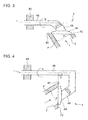
- FIG.3 is a side view of the wastegate valve in a modified example where the inclination angle ⁇ of the wastegate valve of FIG.1 is set approximately 0°.
- FIG.4 is a side view of the wastegate valve in another modified example where the inclination angle ⁇ of the wastegate valve of FIG.1 is set approximately 90°.
- the inclination angle ⁇ is set as 0° ⁇ 90° as shown in FIG.1 , FIG.3 and FIG.4 , the resolving power of the stroke of the wastegate valve is precise and the flow rate of the exhaust gas through the wastegate valve changes slowly in response to the valve opening.
- FIG.5 is a side view of the wastegate valve in a modified example where the inclination angle ⁇ of the wastegate valve of FIG.1 is set approximately 0°, i.e. the valve seat being arranged in the plane perpendicular to the axial direction of the bypass path.
- FIG.6 is a side view of the wastegate valve in a modified example where the inclination angle ⁇ of the wastegate valve of FIG.5 is set approximately 0°.
- FIG.7 is a side view of the wastegate valve in another modified example where the inclination angle ⁇ of the wastegate valve of FIG.5 is set approximately 90°.
- the inclination angle ⁇ is set approximately 0°, i.e.
- valve seat being arranged in the plane perpendicular to the axial direction of the bypass path and the inclination angle ⁇ is set in the range of 0° to 90°, the resolving power of the stroke of the wastegate valve is precise and thus, the flow rate of the exhaust gas through the wastegate valve changes slowly in response to the valve opening.
- FIG.8 is a graph showing a relationship between a rotation amount of the wastegate valve and a flow rate through the wastegate valve/a flow rate at full open [%] regarding the wastegate valve of the embodiment shown in FIG.1 .
- the vertical axis represents the flow rate through the wastegate valve / the flow rate in a full-open state
- the horizontal axis represents the rotation amount of the wastegate valve.
- the rotation amount herein means a rotation amount of the valving element 44 being rotated around a rotation center of the axial direction of the bypass path 2, i.e. the direction perpendicular to the flow f of the exhaust gas. The rotation amount corresponds to the valve opening.
- FIG.8 shows four lines on the graph.
- Each line on the graph represents the inclination angle ⁇ of FIG.1 1 set at 0°, 45°, 60° or 70°.
- the line with the inclination angle ⁇ of 0° represents a case of the conventional wastegate valve.
- the effectiveness of stable control of the flow rate of the exhaust gas is small and thus, it is necessary to set a lower limit of the inclination angle ⁇ to 45°.
- the lower limit of the inclination angle ⁇ is preferably set to 60°.
- the wastegate valve which is provided in the bypass path to bypass the turbine of the turbocharger in the exhaust gas path and which opens and closes the bypass path, can be used to control the flow rate of the exhaust gas passing through the bypass path easily and stably by controlling the opening degree of the wastegate valve.
Abstract
Description
- The present invention relates to a wastegate valve which is provided in a bypass path bypassing a turbine of a turbocharger in an exhaust gas path of an engine and which opens and closes the bypass path.
- In a turbocharger which compresses intake air for an engine, a bypass path is provided to prevent over-rotation of the turbocharger due to increased pressure of the exhaust gas. The bypass pass bypasses the turbine from the exhaust gas inlet side of the outlet side of the turbine of the turbocharger and is opened and closed by the wastegate valve.
-
FIG.9 shows a structure of a supply and exhaust device of the engine to which a wastegate valve is applied.
InFIG.9 , asupply path 58 is connected to anengine 52 via asupply manifold 56 and anexhaust path 60 is connected to theengine 52 via anexhaust manifold 54.
In thesupply path 58, acompressor 70a of theturbocharger 70 is provided. Thecompressor 70a is coaxially arranged with and driven by aturbine 70b. On a downstream side of thecompressor 70a in thesupply path 58, anintercooler 62 is provided to cool the intake air flowing in thesupply path 58 by heat exchange with ambient air. On a downstream side of theintercooler 62 in thesupply path 58, athrottle valve 64 is provided to regulate a flow rate of the intake air flowing in thesupply path 58. - In the
exhaust path 60, theturbine 70b of theturbocharger 70 is provided. Theturbine 70b is driven by the exhaust gas from theengine 52. In theexhaust path 60, abypass path 2 connects an exhaust gas inlet side of theturbine 70b to an exhaust gas outlet side to bypass theturbine 70b. In thebypass path 2, awastegate valve 4 is provided to open and close thebypass path 2. - With the above structure, once the
engine 52 starts, the exhaust gas from theengine 52 is collected into anexhaust gas manifold 54 and fed to theturbine 70b of theturbocharger 70 through theair exhaust path 60 to drive theturbine 70b. - In the
turbocharger 70, thecompressor 70a is driven by theturbine 70b to compress the intake air. The compressed intake air is supplied through asupply manifold 56 to theengine 2 via thesupply path 58, theintercooler 62 and thesupply path 58. - In the case of preventing the over-rotation of the
turbocharger 2, the exhaust gas from theengine 2 may be led to the bypass path to bypass theturbine 70b by opening thewastegate valve 4. - For instance, a pressure at an outlet of the
compressor 70a may be detected and once the detected pressure exceeds a preset threshold value, thewastegate valve 4 may be opened to allow the exhaust gas to bypass theturbine 70b, thereby preventing the over-rotation of the turbocharger. - As a conventional wastegate valve, a swing-type valve having a valve seat in a plane perpendicular to an axial direction of the bypass path at an open end thereof. This type of the wastegate valve is disclosed in
Patent Literature 1. -
FIG. 11 is a side view of the conventional wastegate valve.FIG. 12 is a fragmentary side view taken in a direction of an arrow B ofFIG.11. FIG.11 and FIG.12 show local sectional views.
InFIG.11 and FIG.12 , awastegate valve 104 includes avalving element 144 and avalve seat 142 on which thevalving element 144 is placed. Thevalving element 144 is supported by apivot shaft 146 via asupport arm 148 pivotable in a direction of an arrow W' around an axial center r' of the pivot shaft. Thewastegate valve 104 is closed by placing thevalving element 144 on thevalve seat 142.
InFIG.11 and FIG.12 , thevalve seat 142 is arranged in the plane which is perpendicular to the axial direction of the bypass path. - To open the
valving element 144, thepivot shaft 146 is turned so that thevalving element 144 is moved away from thevalve seat 142 in the direction of the arrow W' to a valve-open position. -
- [PTL 1]
-
JP 2009-92026A - Previously, the wastegate valve was controlled to fully open when a parameter related to the over-rotation of the turbocharger such as an outlet pressure of the compressor exceeds a preset threshold, and to be fully closed otherwise.
In recent years, it is desired to use the wastegate valve positively for controlling the turbocharger and it is preferable to be able to regulate the flow rate of the exhaust gas passing through the bypass path of the turbine by half-opening the wastegate valve in addition to full-opening and shut-down thereof. -
FIG. 10 is a graph showing a relationship between an opening degree of the wastegate valve and the flow rate through the valve/the flow rate in a full-open state [%] regarding the conventional wastegate valve shown inFIG.11 and FIG.12 . Herein, "the flow rate in a full-open state" is a flow rate of the exhaust gas passing through the bypass path when the wastegate valve is fully open, whereas "the flow rate through the valve" is a flow rate of the exhaust gas passing through the bypass path at each opening degree of the wastegate valve. - As shown in
FIG.10 , in the conventional wastegate valve having the valve seat arranged in the plane perpendicular to the axial direction of the bypass path, the slope of the line is not constant. Particularly with small opening degree, the slope is sharp, i.e. the flow rate of the exhaust gas passing through the bypass path changes drastically with a slight change in the opening degree of the wastegate valve. Therefore, it was difficult to control the flow rate of the exhaust gas with use of the conventional wastegate valve and this is very evident in the region where the valve opening is small. - When there is clearance for or looseness due to assembling of the wastegate valve, in the region where the valve opening is small, a flow change of the exhaust gas causes the opening degree of the valve to change for the amount corresponding to the clearance or looseness and thus, leading to a drastic change in the flow rate of the exhaust gas.
- As described above, in the conventional wastegate valve having the valve seat arranged in the plane perpendicular to the axial direction of the bypass path, it remains difficult to control the flow rate of the exhaust gas passing through the bypass path by regulating the opening degree of the wastegate valve.
- In recent years, application of an actuator equipped with a stroke sensor is making progress and precise control of a supercharging pressure from the engine side is desired. As a method for performing more precise control, there is a VG Nozzle. However, the VG Nozzle is expensive and has a complicated structure and thus, the VG nozzle is not reliable enough to be used for a gasoline engine at high temperature.
- In view of the above issues, it is an object of the present invention is to provide a wastegate valve which is provided in the bypass path bypassing the turbine of the turbocharger in the exhaust gas path to open and close the bypass path and which can control the flow rate of the exhaust gas passing through the bypass path easily and stably by controlling the opening degree thereof.
- To solve the above issues, the present invention provides a wastegate valve which is provided in a bypass path bypassing a turbine of a turbocharger in an exhaust gas path of an engine and which opens and closes the bypass path, the valve including, but not limited to:
- a valve seat which is formed in a plane perpendicular to or tilted with an inclination angle with respect to an axial direction of the bypass path; and
- a valving element which is pivotable around a pivot point which has a relationship of 0°<β<90° with respect to the plane including the valve seat where β is an inclination angle, the valving element being moved away from or closer to the valve seat by pivotation of the valving element to open or close the valve.
- By this, a resolving power of the stroke of the wastegate valve becomes precise. Therefore, the flow rate of the exhaust gas passing through the wastegate valve changes slowly in response to opening of the valve. This is more evident in the region where the opening degree of wastegate valve is small.
Therefore, it becomes easy to control the flow rate of the exhaust gas passing through the bypass path by regulating the opening degree of the wastegate valve in all regions including the region where the opening degree of the valve is small. - Further, the valving element may be supported by a pivot shaft such that the valving element is pivotable around a shaft center of the pivot shaft, the pivot shaft having the inclination angle of β with respect to the plane including the valve seat.
By this, it becomes easy to allow the valving element to pivot around the pivot center in the direction perpendicular to the flow of the exhaust gas. - Furthermore, the valve seat may have an inclination angle α of 45° to 80° with respect to the plane which is perpendicular to the axial direction of the bypass path.
At the inclination angle α greater than 80°, it is difficult to achieve enough sealing when the wastegate valve is closed and the exhaust gas possibly leaks through the wastegate valve even in the closed state of the wastegate valve.
At the inclination angle α below 45°, the effectiveness of stable control of the flow rate of the exhaust gas is small. - Furthermore, the valve seat may have an inclination angle α of 60° to 70° with respect to the plane perpendicular to the axial direction of the bypass path.
At the inclination angle α not greater than 70°, it is possible to attain high sealing capability. And at the inclination angle α not less than 60°, it is possible to control the flow rate of the exhaust gas passing through the wastegate valve in a more stable manner. - The wastegate valve provided in the bypass path bypassing the turbine of the turbocharger in the exhaust gas path to open and close the bypass path is now capable of controlling the flow rate of the exhaust gas passing through the bypass path easily and stably by controlling the opening degree thereof.
-
- [
FIG.1 ]
FIG.1 is a side view of a wastegate valve of the present invention, with a local sectional view to show an inclination angle α. - [
FIG.2 ]
FIG.2 is a fragmentary view taken in a direction of an arrow A ofFIG.1 . - [
FIG.3 ]
FIG.3 is a side view of the wastegate valve in a modified example where an inclination angle β of the wastegate valve ofFIG.1 is set approximately 0°. - [
FIG.4 ]
FIG.4 is a side view of the wastegate valve in another modified example where the inclination angle β of the wastegate valve ofFIG.1 is set approximately 90°. - [
FIG.5 ]
FIG.5 is a side view of the wastegate valve in a modified example where the inclination angle α of the wastegate valve ofFIG.1 is set approximately 0°. - [
FIG.6 ]
FIG.6 is a side view of the wastegate valve in a modified example where the inclination angle β of the wastegate valve ofFIG.5 is set approximately 0°. - [
FIG.7 ]
FIG.7 is a side view of the wastegate valve in another modified example where the inclination angle β of the wastegate valve ofFIG.5 is set approximately 90°. - [
FIG.8 ]
FIG.8 is a graph showing a relationship between a rotation amount of the wastegate valve and a flow rate through the wastegate valve/a flow rate at full open [%] regarding the wastegate valve of the embodiment shown inFIG.1 . - [
FIG.9 ]
FIG.9 shows a structure of a supply and exhaust device of the engine to which the wastegate valve is applied. - [
FIG. 10 ]
FIG.10 is a graph showing a relationship between an opening degree and a flow rate through a valve/a flow rate in a full-open state [%] regarding a conventional wastegate valve. - [
FIG.11 ]
FIG.11 is a side view of the conventional wastegate valve with a local sectional view. - [
FIG.12 ]
FIG.12 is a fragmentary view taken in a direction of an arrow B ofFIG.11 . - A preferred embodiment of the present invention will now be detailed with reference to the accompanying drawings. It is intended, however, that unless particularly specified, dimensions, materials, relative positions and so forth of the constituent parts in the embodiments shall be interpreted as illustrative only not as limitative of the scope of the present invention.
- In the embodiment, a structure of a supply and exhaust device of the engine to which a wastegate valve of the present invention is applied substantially the same as the one shown in
FIG.9 and thus, the description regardingFIG.9 may be applied to the embodiment to save further explanation. -
FIG.1 is a side view of a wastegate valve of the present invention, with a local sectional view to show an inclination angle α.FIG.2 is a fragmentary view taken in a direction of an arrow A ofFIG.1 .
The wastegate valve of the present embodiment is now explained in reference toFIG.1 and FIG.2 . - The
wastegate valve 4 opens when avalving element 144 seats on avalve seat 142. Thevalve seat 42 is disposed at an end of abypass path 2 and is formed by an open end of thebypass path 2 opening to the air exhaust path 60 (not shown inFIG.1 ). Thevalving element 44 is supported by apivot shaft 46 such that thevalving element 44 is pivotable in a direction of an arrow W around a shaft center r of thepivot shaft 46 via asupport arm 48. - The
valve seat 42 forming the open end of the bypass path is formed in a plane which has an inclination angle α with respect to an assumed plane p which is perpendicular to a flow f of the exhaust gas in thebypass path 2. - The
pivot shaft 46 supports thevalving element 44 via thesupport arm 48. Thepivot shaft 46 has a relationship of 0°<β<90° where β is an inclination angle between the shaft center r of thepivot shaft 46 and the plane where thevalve seat 42 is formed. In the present embodiment, the shaft center r of thepivot shaft 46 is in a plane parallel to the assumed plane p and β=α as an example.
Accordingly, to open the valving element, thepivot shaft 46 is turned to pivot thevalving element 44 in the direction of the arrow W via thesupport arm 48 so as to detach thevalving element 44 from thevalve seat 42. - In this manner, the
valve seat 42 forming the open end of the bypass path is formed in the plane which has the inclination angle α with respect to the assumed plane p perpendicular to the flow f of the exhaust gas, i.e. the axial direction of thebypass path 2. Further, thevalving element 44 is disposed such that the pivot center is angled with respect to the plane where thevalve seat 42 is formed. Thus, a resolving power of the wastegate increases, i.e. the flow rate of the exhaust gas with respect to the stroke of the wastegate valve being obtained with higher precision. By this, the flow rate of the exhaust gas passing through the wastegate valve changes slowly in response to the opening of the valve. This is particularly evident in the region where the opening degree of wastegate valve is small. - Therefore, the flow rate of the exhaust gas passing through the
bypass path 2 can be easily controlled by adjusting the opening degree of the wastegate valve, even in the region where the opening of the valve is small.
When there is clearance for or looseness due to assembling of the wastegate valve, even if the opening degree of the valve changes slightly due to the clearance or the looseness, the flow rate of the exhaust gas through the wastegate valve changes slowly in response to the opening of the valve. This causes little change in the flow rate of the exhaust gas through the wastegate valve, hence causing no issue. -
FIG.3 is a side view of the wastegate valve in a modified example where the inclination angle β of the wastegate valve ofFIG.1 is set approximately 0°.FIG.4 is a side view of the wastegate valve in another modified example where the inclination angle β of the wastegate valve ofFIG.1 is set approximately 90°.
When the inclination angle β is set as 0°<β<90° as shown inFIG.1 ,FIG.3 and FIG.4 , the resolving power of the stroke of the wastegate valve is precise and the flow rate of the exhaust gas through the wastegate valve changes slowly in response to the valve opening. -
FIG.5 is a side view of the wastegate valve in a modified example where the inclination angle α of the wastegate valve ofFIG.1 is set approximately 0°, i.e. the valve seat being arranged in the plane perpendicular to the axial direction of the bypass path.FIG.6 is a side view of the wastegate valve in a modified example where the inclination angle β of the wastegate valve ofFIG.5 is set approximately 0°.FIG.7 is a side view of the wastegate valve in another modified example where the inclination angle β of the wastegate valve ofFIG.5 is set approximately 90°.
When the inclination angle α is set approximately 0°, i.e. the valve seat being arranged in the plane perpendicular to the axial direction of the bypass path and the inclination angle β is set in the range of 0° to 90°, the resolving power of the stroke of the wastegate valve is precise and thus, the flow rate of the exhaust gas through the wastegate valve changes slowly in response to the valve opening. -
FIG.8 is a graph showing a relationship between a rotation amount of the wastegate valve and a flow rate through the wastegate valve/a flow rate at full open [%] regarding the wastegate valve of the embodiment shown inFIG.1 . In the graph, the vertical axis represents the flow rate through the wastegate valve / the flow rate in a full-open state, and the horizontal axis represents the rotation amount of the wastegate valve. The rotation amount herein means a rotation amount of thevalving element 44 being rotated around a rotation center of the axial direction of thebypass path 2, i.e. the direction perpendicular to the flow f of the exhaust gas. The rotation amount corresponds to the valve opening. -
FIG.8 shows four lines on the graph. Each line on the graph represents the inclination angle α ofFIG.1 1 set at 0°, 45°, 60° or 70°. The line with the inclination angle α of 0° represents a case of the conventional wastegate valve.
As evident fromFIG.8 , the greater the inclination angle α is, the slower the flow rate of the exhaust gas through the wastegate valve changes in response to the change in the opening degree of the wastegate valve. Therefore, with increased inclination angle α, the flow rate of the exhaust gas passing through the wastegate valve can be controlled in a stable manner by adjusting the opening degree of the wastegate valve.
At the inclination angle α below 45°, the effectiveness of stable control of the flow rate of the exhaust gas is small and thus, it is necessary to set a lower limit of the inclination angle α to 45°. To further improve the stable control of the flow rate of the exhaust gas, the lower limit of the inclination angle α is preferably set to 60°. - If the inclination angle α is too great, it is difficult to achieve enough sealing when the valve is closed. At the inclination angle α greater than 80°, the exhaust gas is likely to pass through the wastegate valve even in the closed state. Thus, it is necessary to set an upper limit of the inclination angle α to 80°, preferably to 70°.
- At the inclination angle α of 45° to 80°, preferably 60° to 70°, it is possible to attain high sealing capability. Further by regulating the opening degree of the wastegate valve, it is possible to stably control the flow rate of the exhaust gas passing through the wastegate valve.
- The wastegate valve which is provided in the bypass path to bypass the turbine of the turbocharger in the exhaust gas path and which opens and closes the bypass path, can be used to control the flow rate of the exhaust gas passing through the bypass path easily and stably by controlling the opening degree of the wastegate valve.
Claims (4)
- A wastegate valve which is provided in a bypass path bypassing a turbine of a turbocharger in an exhaust gas path of an engine and which opens and closes the bypass path, the valve comprising:a valve seat which is formed in a plane perpendicular to or tilted with an inclination angle with respect to an axial direction of the bypass path; anda valving element which is pivotable around a pivot point which has a relationship of 0°<β<90° with respect to the plane including the valve seat where β is an inclination angle, the valving element being moved away from or closer to the valve seat by pivotation of the valving element to open or close the valve.
- The wastegate valve according to claim 1,
wherein the valving element is supported by a pivot shaft such that the valving element is pivotable around a shaft center of the pivot shaft, the pivot shaft having the inclination angle of β with respect to the plane including the valve seat. - The wastegate valve according to claim 1 or 2,
wherein the valve seat has an inclination angle α of 45° to 80° with respect to a plane which is perpendicular to the axial direction of the bypass path. - The wastegate valve according to claim 3,
wherein the inclination angle α of the valve seat is 60° to 70°.
Applications Claiming Priority (2)
| Application Number | Priority Date | Filing Date | Title |
|---|---|---|---|
| JP2010006685A JP2011144762A (en) | 2010-01-15 | 2010-01-15 | Waste gate valve |
| PCT/JP2011/050482 WO2011087069A1 (en) | 2010-01-15 | 2011-01-13 | Waste gate valve |
Publications (3)
| Publication Number | Publication Date |
|---|---|
| EP2444625A1 true EP2444625A1 (en) | 2012-04-25 |
| EP2444625A4 EP2444625A4 (en) | 2014-11-05 |
| EP2444625B1 EP2444625B1 (en) | 2016-01-13 |
Family
ID=44304339
Family Applications (1)
| Application Number | Title | Priority Date | Filing Date |
|---|---|---|---|
| EP11732939.1A Not-in-force EP2444625B1 (en) | 2010-01-15 | 2011-01-13 | Waste gate valve |
Country Status (6)
| Country | Link |
|---|---|
| US (1) | US8733101B2 (en) |
| EP (1) | EP2444625B1 (en) |
| JP (1) | JP2011144762A (en) |
| KR (1) | KR101324882B1 (en) |
| CN (1) | CN102472160B (en) |
| WO (1) | WO2011087069A1 (en) |
Cited By (9)
| Publication number | Priority date | Publication date | Assignee | Title |
|---|---|---|---|---|
| WO2014053279A1 (en) * | 2012-10-01 | 2014-04-10 | Continental Automotive Gmbh | Wastegate valve and method for installing a wastegate valve into the turbine housing of an exhaust-gas turbocharger |
| EP2743475A1 (en) * | 2012-12-17 | 2014-06-18 | Honeywell International Inc. | Wastegate |
| EP2784286A1 (en) * | 2013-03-28 | 2014-10-01 | OTICS Corporation | Turbocharger |
| EP2824371A1 (en) * | 2013-07-12 | 2015-01-14 | Cummins Ltd | Turbine |
| FR3009019A1 (en) * | 2013-07-23 | 2015-01-30 | Renault Sa | TURBOCOMPRESSOR DISCHARGE VALVE |
| WO2016005370A1 (en) * | 2014-07-09 | 2016-01-14 | Jaguar Land Rover Limited | Wastegate valve |
| WO2017108160A1 (en) * | 2015-12-21 | 2017-06-29 | Ihi Charging Systems International Gmbh | Exhaust gas guide section for an exhaust gas turbocharger and method for operating an exhaust gas turbocharger |
| WO2017108162A1 (en) * | 2015-12-21 | 2017-06-29 | Ihi Charging Systems International Gmbh | Exhaust gas guide section for an exhaust gas turbocharger and method for operating an exhaust gas turbocharger |
| WO2020076619A1 (en) * | 2018-10-08 | 2020-04-16 | Borgwarner Inc. | Wastegate assembly for use in a turbocharger and system including the same |
Families Citing this family (19)
| Publication number | Priority date | Publication date | Assignee | Title |
|---|---|---|---|---|
| US20150040561A1 (en) * | 2012-03-30 | 2015-02-12 | Toyota Jidosha Kabushiki Kaisha | Control device for internal combustion engine |
| JP5939052B2 (en) * | 2012-06-26 | 2016-06-22 | 株式会社Ihi | Turbocharger |
| DE102012111558A1 (en) * | 2012-11-29 | 2014-06-05 | Firma IHI Charging Systems International GmbH | Regulating device for an exhaust gas guide section of a turbine |
| KR101383720B1 (en) * | 2012-12-13 | 2014-04-08 | 기아자동차(주) | Turbo charger with wastegate |
| KR20150097567A (en) | 2012-12-19 | 2015-08-26 | 보르그워너 인코퍼레이티드 | Methods and structure for reducing losses in 90 degree waste gates for turbochargers |
| WO2014179105A1 (en) * | 2013-04-30 | 2014-11-06 | Borgwarner Inc. | Control arrangement of an exhaust-gas turbocharger |
| US9376930B2 (en) * | 2013-10-30 | 2016-06-28 | Hyundai Motor Company | Waste gate valve |
| DE102014102636A1 (en) * | 2014-02-27 | 2015-08-27 | Ihi Charging Systems International Gmbh | Exhaust gas turbocharger with a Umblaseeinrichtung |
| DE102014102635A1 (en) * | 2014-02-27 | 2015-09-10 | Ihi Charging Systems International Gmbh | Exhaust gas turbocharger with a Umblaseeinrichtung |
| CN106662006B (en) | 2014-08-29 | 2019-03-29 | 株式会社Ihi | Booster |
| JP6458676B2 (en) * | 2014-09-12 | 2019-01-30 | 株式会社デンソー | Valve device |
| DE102015001763A1 (en) * | 2015-02-11 | 2016-08-11 | GM Global Technology Operations LLC (n. d. Ges. d. Staates Delaware) | Wastegate valve actuator |
| DE102016204077A1 (en) * | 2015-05-18 | 2016-11-24 | Bosch Mahle Turbo Systems Gmbh & Co. Kg | turbocharger |
| US10526958B2 (en) * | 2016-03-23 | 2020-01-07 | Borgwarner Inc. | Reverse offset wastegate valve assembly for improved catalyst light-off performance |
| DE102016208159B4 (en) * | 2016-05-12 | 2022-02-03 | Vitesco Technologies GmbH | Turbine for an exhaust gas turbocharger with a double-flow turbine housing and a valve for connecting the flows |
| JP6566134B2 (en) * | 2016-06-07 | 2019-08-28 | 株式会社Ihi | Variable flow rate valve mechanism and turbocharger |
| US10125671B2 (en) * | 2016-11-09 | 2018-11-13 | Ford Global Technologies, Llc | Wastegate for an engine system |
| KR101981464B1 (en) | 2017-12-14 | 2019-05-23 | 영화금속 주식회사 | Structure and method for fixing bush to turbine housing |
| WO2022038653A1 (en) * | 2020-08-17 | 2022-02-24 | 三菱重工エンジン&ターボチャージャ株式会社 | Waste gate valve device, turbine, and turbocharger |
Citations (5)
| Publication number | Priority date | Publication date | Assignee | Title |
|---|---|---|---|---|
| US401680A (en) * | 1889-04-16 | Edwaed s | ||
| US413941A (en) * | 1889-10-29 | Valve for pneumatic pipes or tubes | ||
| WO2003033950A1 (en) * | 2001-10-19 | 2003-04-24 | Saab Automobile Ab | Valve and motor arrangement |
| US20070257223A1 (en) * | 2006-05-08 | 2007-11-08 | Van De Moosdijk Frank | Valve assembly |
| US20090151352A1 (en) * | 2006-05-31 | 2009-06-18 | Mcewan Jim | Turbocharger with dual wastegate |
Family Cites Families (10)
| Publication number | Priority date | Publication date | Assignee | Title |
|---|---|---|---|---|
| JPS5588018U (en) | 1978-12-14 | 1980-06-18 | ||
| JPH0439388Y2 (en) * | 1985-07-22 | 1992-09-16 | ||
| DE3922491A1 (en) * | 1988-08-23 | 1990-03-01 | Asea Brown Boveri | GAS DYNAMIC PRESSURE WAVE CHARGER WITH EXHAUST BYPASS |
| US5046317A (en) | 1989-06-09 | 1991-09-10 | Allied-Signal Inc. | Wastegate valve for turbocharger |
| JP2004332686A (en) | 2003-05-12 | 2004-11-25 | Hitachi Ltd | Exhaust passage switching device for internal combustion engine |
| DE102004048860B4 (en) * | 2004-10-07 | 2017-05-24 | Robert Bosch Gmbh | Method and device for controlling an actuator in a mass flow line |
| US20090014674A1 (en) * | 2005-05-10 | 2009-01-15 | Borgwarner Inc. | Valve regulation assembly |
| US7360362B2 (en) * | 2006-01-20 | 2008-04-22 | Honeywell International, Inc. | Two-stage turbocharger system with integrated exhaust manifold and bypass assembly |
| JP4885105B2 (en) | 2007-10-11 | 2012-02-29 | 三菱重工業株式会社 | Fluid switching valve device, exhaust gas control valve and wastegate valve provided with the same |
| JP5260082B2 (en) * | 2008-02-26 | 2013-08-14 | 三菱重工業株式会社 | Turbocharger exhaust bypass valve |
-
2010
- 2010-01-15 JP JP2010006685A patent/JP2011144762A/en not_active Withdrawn
-
2011
- 2011-01-13 US US13/388,006 patent/US8733101B2/en not_active Expired - Fee Related
- 2011-01-13 EP EP11732939.1A patent/EP2444625B1/en not_active Not-in-force
- 2011-01-13 CN CN201180002876.4A patent/CN102472160B/en not_active Expired - Fee Related
- 2011-01-13 KR KR1020127000904A patent/KR101324882B1/en not_active IP Right Cessation
- 2011-01-13 WO PCT/JP2011/050482 patent/WO2011087069A1/en active Application Filing
Patent Citations (5)
| Publication number | Priority date | Publication date | Assignee | Title |
|---|---|---|---|---|
| US401680A (en) * | 1889-04-16 | Edwaed s | ||
| US413941A (en) * | 1889-10-29 | Valve for pneumatic pipes or tubes | ||
| WO2003033950A1 (en) * | 2001-10-19 | 2003-04-24 | Saab Automobile Ab | Valve and motor arrangement |
| US20070257223A1 (en) * | 2006-05-08 | 2007-11-08 | Van De Moosdijk Frank | Valve assembly |
| US20090151352A1 (en) * | 2006-05-31 | 2009-06-18 | Mcewan Jim | Turbocharger with dual wastegate |
Non-Patent Citations (1)
| Title |
|---|
| See also references of WO2011087069A1 * |
Cited By (16)
| Publication number | Priority date | Publication date | Assignee | Title |
|---|---|---|---|---|
| US9885278B2 (en) | 2012-10-01 | 2018-02-06 | Continental Automotive Gmbh | Wastegate valve and method for installing a wastegate valve into the turbine housing of an exhaust-gas turbocharger |
| CN104685182A (en) * | 2012-10-01 | 2015-06-03 | 大陆汽车有限公司 | Wastegate valve and method for installing a wastegate valve into the turbine housing of an exhaust-gas turbocharger |
| WO2014053279A1 (en) * | 2012-10-01 | 2014-04-10 | Continental Automotive Gmbh | Wastegate valve and method for installing a wastegate valve into the turbine housing of an exhaust-gas turbocharger |
| EP2743475A1 (en) * | 2012-12-17 | 2014-06-18 | Honeywell International Inc. | Wastegate |
| US9874139B2 (en) | 2012-12-17 | 2018-01-23 | Honeywell International Inc. | Assembly with wastegate opening, wastegate seat and wall |
| EP2784286A1 (en) * | 2013-03-28 | 2014-10-01 | OTICS Corporation | Turbocharger |
| EP2824371A1 (en) * | 2013-07-12 | 2015-01-14 | Cummins Ltd | Turbine |
| US10041398B2 (en) | 2013-07-12 | 2018-08-07 | Cummins Ltd. | Turbine |
| FR3009019A1 (en) * | 2013-07-23 | 2015-01-30 | Renault Sa | TURBOCOMPRESSOR DISCHARGE VALVE |
| WO2016005370A1 (en) * | 2014-07-09 | 2016-01-14 | Jaguar Land Rover Limited | Wastegate valve |
| WO2017108162A1 (en) * | 2015-12-21 | 2017-06-29 | Ihi Charging Systems International Gmbh | Exhaust gas guide section for an exhaust gas turbocharger and method for operating an exhaust gas turbocharger |
| WO2017108160A1 (en) * | 2015-12-21 | 2017-06-29 | Ihi Charging Systems International Gmbh | Exhaust gas guide section for an exhaust gas turbocharger and method for operating an exhaust gas turbocharger |
| US10662869B2 (en) | 2015-12-21 | 2020-05-26 | Ihi Charging Systems International Gmbh | Exhaust gas guide for an exhaust gas turbocharger and method for operating an exhaust gas turbocharger |
| US10890084B2 (en) | 2015-12-21 | 2021-01-12 | Ihi Charging Systems International Gmbh | Exhaust gas guide section for an exhaust gas turbocharger and method for operating an exhaust gas turbocharger |
| WO2020076619A1 (en) * | 2018-10-08 | 2020-04-16 | Borgwarner Inc. | Wastegate assembly for use in a turbocharger and system including the same |
| US11634998B2 (en) | 2018-10-08 | 2023-04-25 | Borgwarner Inc. | Wastegate assembly for use in a turbocharger and system including the same |
Also Published As
| Publication number | Publication date |
|---|---|
| CN102472160B (en) | 2015-04-01 |
| KR101324882B1 (en) | 2013-11-01 |
| US8733101B2 (en) | 2014-05-27 |
| EP2444625A4 (en) | 2014-11-05 |
| JP2011144762A (en) | 2011-07-28 |
| US20130199175A1 (en) | 2013-08-08 |
| EP2444625B1 (en) | 2016-01-13 |
| CN102472160A (en) | 2012-05-23 |
| KR20120017090A (en) | 2012-02-27 |
| WO2011087069A1 (en) | 2011-07-21 |
Similar Documents
| Publication | Publication Date | Title |
|---|---|---|
| US8733101B2 (en) | Wastegate valve | |
| EP2558752B1 (en) | Multifunction valve | |
| EP1598539B1 (en) | Turbocharger and EGR System | |
| EP2321508B1 (en) | Butterfly valve for turbocharger systems | |
| US10294856B2 (en) | VTG turbocharger with wastegate controlled by a common actuator | |
| US7712312B2 (en) | Pressure balanced swing valve for engine system | |
| KR101794365B1 (en) | Fresh gas supply device for an internal combustion engine and method for operating said type of fresh gas supply device | |
| EP3171011B1 (en) | An exhaust gas recirculation apparatus | |
| BRPI0802492A2 (en) | method of controlling an internal combustion engine supercharged by a turbo compressor | |
| US10697377B2 (en) | Turbine supercharger and two-stage supercharging system | |
| CN109154229B (en) | Turbine for an exhaust-gas turbocharger | |
| US20130309106A1 (en) | Turbocharger | |
| CN110513159B (en) | Variable turbine geometry blade with single-shaft, self-centering pivot feature | |
| RU2011115032A (en) | DEVICE FOR SUPPLYING A FRESH MIXTURE MIXTURE FOR INTERNAL COMBUSTION ENGINES WITH A GAS TURBINE PRESSURIZER AND A METHOD FOR ITS CONTROL | |
| US20130206117A1 (en) | Exhaust gas recirculation apparatus for engine | |
| US20160024998A1 (en) | A compact rotary wastegate valve | |
| US10844778B2 (en) | Exhaust-flow-rate control valve, and two-stage supercharging system provided with same | |
| EP3379052A1 (en) | Engine with exhaust turbocharger | |
| KR20110115533A (en) | Method and device for operation a flap actuator for controlling a mass flow as well as a flap actuator | |
| KR20150123332A (en) | Integrated vane stops for variable-geometry turbocharger mechanism | |
| WO2015066258A1 (en) | Rotary wastegate valve | |
| US10072565B2 (en) | Wastegate closed position detent feature | |
| EP1435451A2 (en) | EGR valve for a turbocharged diesel engine | |
| EP2808514B1 (en) | Compressor Bypass Valve | |
| JP2011058425A (en) | Adjusting valve and supercharging apparatus |
Legal Events
| Date | Code | Title | Description |
|---|---|---|---|
| PUAI | Public reference made under article 153(3) epc to a published international application that has entered the european phase |
Free format text: ORIGINAL CODE: 0009012 |
|
| 17P | Request for examination filed |
Effective date: 20120119 |
|
| AK | Designated contracting states |
Kind code of ref document: A1 Designated state(s): AL AT BE BG CH CY CZ DE DK EE ES FI FR GB GR HR HU IE IS IT LI LT LU LV MC MK MT NL NO PL PT RO RS SE SI SK SM TR |
|
| DAX | Request for extension of the european patent (deleted) | ||
| A4 | Supplementary search report drawn up and despatched |
Effective date: 20141007 |
|
| RIC1 | Information provided on ipc code assigned before grant |
Ipc: F01D 17/10 20060101ALI20140930BHEP Ipc: F16K 1/20 20060101ALI20140930BHEP Ipc: F02B 37/16 20060101ALI20140930BHEP Ipc: F02B 37/18 20060101AFI20140930BHEP Ipc: F02B 39/00 20060101ALI20140930BHEP |
|
| RIC1 | Information provided on ipc code assigned before grant |
Ipc: F02B 39/00 20060101ALI20150617BHEP Ipc: F02B 37/16 20060101ALI20150617BHEP Ipc: F02B 37/18 20060101AFI20150617BHEP Ipc: F01D 17/10 20060101ALI20150617BHEP Ipc: F16K 1/20 20060101ALI20150617BHEP |
|
| GRAP | Despatch of communication of intention to grant a patent |
Free format text: ORIGINAL CODE: EPIDOSNIGR1 |
|
| INTG | Intention to grant announced |
Effective date: 20150731 |
|
| GRAS | Grant fee paid |
Free format text: ORIGINAL CODE: EPIDOSNIGR3 |
|
| GRAA | (expected) grant |
Free format text: ORIGINAL CODE: 0009210 |
|
| AK | Designated contracting states |
Kind code of ref document: B1 Designated state(s): AL AT BE BG CH CY CZ DE DK EE ES FI FR GB GR HR HU IE IS IT LI LT LU LV MC MK MT NL NO PL PT RO RS SE SI SK SM TR |
|
| REG | Reference to a national code |
Ref country code: GB Ref legal event code: FG4D |
|
| REG | Reference to a national code |
Ref country code: CH Ref legal event code: EP |
|
| REG | Reference to a national code |
Ref country code: FR Ref legal event code: PLFP Year of fee payment: 6 |
|
| REG | Reference to a national code |
Ref country code: IE Ref legal event code: FG4D |
|
| REG | Reference to a national code |
Ref country code: AT Ref legal event code: REF Ref document number: 770684 Country of ref document: AT Kind code of ref document: T Effective date: 20160215 |
|
| REG | Reference to a national code |
Ref country code: DE Ref legal event code: R096 Ref document number: 602011022643 Country of ref document: DE |
|
| REG | Reference to a national code |
Ref country code: NL Ref legal event code: FP |
|
| REG | Reference to a national code |
Ref country code: LT Ref legal event code: MG4D |
|
| PG25 | Lapsed in a contracting state [announced via postgrant information from national office to epo] |
Ref country code: BE Free format text: LAPSE BECAUSE OF NON-PAYMENT OF DUE FEES Effective date: 20160131 |
|
| REG | Reference to a national code |
Ref country code: AT Ref legal event code: MK05 Ref document number: 770684 Country of ref document: AT Kind code of ref document: T Effective date: 20160113 |
|
| PG25 | Lapsed in a contracting state [announced via postgrant information from national office to epo] |
Ref country code: ES Free format text: LAPSE BECAUSE OF FAILURE TO SUBMIT A TRANSLATION OF THE DESCRIPTION OR TO PAY THE FEE WITHIN THE PRESCRIBED TIME-LIMIT Effective date: 20160113 Ref country code: FI Free format text: LAPSE BECAUSE OF FAILURE TO SUBMIT A TRANSLATION OF THE DESCRIPTION OR TO PAY THE FEE WITHIN THE PRESCRIBED TIME-LIMIT Effective date: 20160113 Ref country code: GR Free format text: LAPSE BECAUSE OF FAILURE TO SUBMIT A TRANSLATION OF THE DESCRIPTION OR TO PAY THE FEE WITHIN THE PRESCRIBED TIME-LIMIT Effective date: 20160414 Ref country code: HR Free format text: LAPSE BECAUSE OF FAILURE TO SUBMIT A TRANSLATION OF THE DESCRIPTION OR TO PAY THE FEE WITHIN THE PRESCRIBED TIME-LIMIT Effective date: 20160113 Ref country code: IT Free format text: LAPSE BECAUSE OF FAILURE TO SUBMIT A TRANSLATION OF THE DESCRIPTION OR TO PAY THE FEE WITHIN THE PRESCRIBED TIME-LIMIT Effective date: 20160113 Ref country code: NO Free format text: LAPSE BECAUSE OF FAILURE TO SUBMIT A TRANSLATION OF THE DESCRIPTION OR TO PAY THE FEE WITHIN THE PRESCRIBED TIME-LIMIT Effective date: 20160413 |
|
| PG25 | Lapsed in a contracting state [announced via postgrant information from national office to epo] |
Ref country code: LT Free format text: LAPSE BECAUSE OF FAILURE TO SUBMIT A TRANSLATION OF THE DESCRIPTION OR TO PAY THE FEE WITHIN THE PRESCRIBED TIME-LIMIT Effective date: 20160113 Ref country code: PL Free format text: LAPSE BECAUSE OF FAILURE TO SUBMIT A TRANSLATION OF THE DESCRIPTION OR TO PAY THE FEE WITHIN THE PRESCRIBED TIME-LIMIT Effective date: 20160113 Ref country code: PT Free format text: LAPSE BECAUSE OF FAILURE TO SUBMIT A TRANSLATION OF THE DESCRIPTION OR TO PAY THE FEE WITHIN THE PRESCRIBED TIME-LIMIT Effective date: 20160513 Ref country code: AT Free format text: LAPSE BECAUSE OF FAILURE TO SUBMIT A TRANSLATION OF THE DESCRIPTION OR TO PAY THE FEE WITHIN THE PRESCRIBED TIME-LIMIT Effective date: 20160113 Ref country code: LV Free format text: LAPSE BECAUSE OF FAILURE TO SUBMIT A TRANSLATION OF THE DESCRIPTION OR TO PAY THE FEE WITHIN THE PRESCRIBED TIME-LIMIT Effective date: 20160113 Ref country code: SE Free format text: LAPSE BECAUSE OF FAILURE TO SUBMIT A TRANSLATION OF THE DESCRIPTION OR TO PAY THE FEE WITHIN THE PRESCRIBED TIME-LIMIT Effective date: 20160113 Ref country code: IS Free format text: LAPSE BECAUSE OF FAILURE TO SUBMIT A TRANSLATION OF THE DESCRIPTION OR TO PAY THE FEE WITHIN THE PRESCRIBED TIME-LIMIT Effective date: 20160513 Ref country code: RS Free format text: LAPSE BECAUSE OF FAILURE TO SUBMIT A TRANSLATION OF THE DESCRIPTION OR TO PAY THE FEE WITHIN THE PRESCRIBED TIME-LIMIT Effective date: 20160113 |
|
| REG | Reference to a national code |
Ref country code: CH Ref legal event code: PL |
|
| REG | Reference to a national code |
Ref country code: DE Ref legal event code: R097 Ref document number: 602011022643 Country of ref document: DE |
|
| PG25 | Lapsed in a contracting state [announced via postgrant information from national office to epo] |
Ref country code: CH Free format text: LAPSE BECAUSE OF NON-PAYMENT OF DUE FEES Effective date: 20160131 Ref country code: EE Free format text: LAPSE BECAUSE OF FAILURE TO SUBMIT A TRANSLATION OF THE DESCRIPTION OR TO PAY THE FEE WITHIN THE PRESCRIBED TIME-LIMIT Effective date: 20160113 Ref country code: LI Free format text: LAPSE BECAUSE OF NON-PAYMENT OF DUE FEES Effective date: 20160131 Ref country code: DK Free format text: LAPSE BECAUSE OF FAILURE TO SUBMIT A TRANSLATION OF THE DESCRIPTION OR TO PAY THE FEE WITHIN THE PRESCRIBED TIME-LIMIT Effective date: 20160113 |
|
| REG | Reference to a national code |
Ref country code: IE Ref legal event code: MM4A |
|
| PLBE | No opposition filed within time limit |
Free format text: ORIGINAL CODE: 0009261 |
|
| STAA | Information on the status of an ep patent application or granted ep patent |
Free format text: STATUS: NO OPPOSITION FILED WITHIN TIME LIMIT |
|
| PG25 | Lapsed in a contracting state [announced via postgrant information from national office to epo] |
Ref country code: SM Free format text: LAPSE BECAUSE OF FAILURE TO SUBMIT A TRANSLATION OF THE DESCRIPTION OR TO PAY THE FEE WITHIN THE PRESCRIBED TIME-LIMIT Effective date: 20160113 Ref country code: SK Free format text: LAPSE BECAUSE OF FAILURE TO SUBMIT A TRANSLATION OF THE DESCRIPTION OR TO PAY THE FEE WITHIN THE PRESCRIBED TIME-LIMIT Effective date: 20160113 Ref country code: RO Free format text: LAPSE BECAUSE OF FAILURE TO SUBMIT A TRANSLATION OF THE DESCRIPTION OR TO PAY THE FEE WITHIN THE PRESCRIBED TIME-LIMIT Effective date: 20160113 Ref country code: CZ Free format text: LAPSE BECAUSE OF FAILURE TO SUBMIT A TRANSLATION OF THE DESCRIPTION OR TO PAY THE FEE WITHIN THE PRESCRIBED TIME-LIMIT Effective date: 20160113 |
|
| REG | Reference to a national code |
Ref country code: FR Ref legal event code: PLFP Year of fee payment: 7 |
|
| 26N | No opposition filed |
Effective date: 20161014 |
|
| PG25 | Lapsed in a contracting state [announced via postgrant information from national office to epo] |
Ref country code: BE Free format text: LAPSE BECAUSE OF FAILURE TO SUBMIT A TRANSLATION OF THE DESCRIPTION OR TO PAY THE FEE WITHIN THE PRESCRIBED TIME-LIMIT Effective date: 20160113 |
|
| PG25 | Lapsed in a contracting state [announced via postgrant information from national office to epo] |
Ref country code: IE Free format text: LAPSE BECAUSE OF NON-PAYMENT OF DUE FEES Effective date: 20160113 |
|
| PG25 | Lapsed in a contracting state [announced via postgrant information from national office to epo] |
Ref country code: SI Free format text: LAPSE BECAUSE OF FAILURE TO SUBMIT A TRANSLATION OF THE DESCRIPTION OR TO PAY THE FEE WITHIN THE PRESCRIBED TIME-LIMIT Effective date: 20160113 Ref country code: BG Free format text: LAPSE BECAUSE OF FAILURE TO SUBMIT A TRANSLATION OF THE DESCRIPTION OR TO PAY THE FEE WITHIN THE PRESCRIBED TIME-LIMIT Effective date: 20160413 |
|
| PG25 | Lapsed in a contracting state [announced via postgrant information from national office to epo] |
Ref country code: MT Free format text: LAPSE BECAUSE OF FAILURE TO SUBMIT A TRANSLATION OF THE DESCRIPTION OR TO PAY THE FEE WITHIN THE PRESCRIBED TIME-LIMIT Effective date: 20160113 |
|
| PG25 | Lapsed in a contracting state [announced via postgrant information from national office to epo] |
Ref country code: MC Free format text: LAPSE BECAUSE OF FAILURE TO SUBMIT A TRANSLATION OF THE DESCRIPTION OR TO PAY THE FEE WITHIN THE PRESCRIBED TIME-LIMIT Effective date: 20160113 |
|
| REG | Reference to a national code |
Ref country code: FR Ref legal event code: PLFP Year of fee payment: 8 |
|
| PG25 | Lapsed in a contracting state [announced via postgrant information from national office to epo] |
Ref country code: HU Free format text: LAPSE BECAUSE OF FAILURE TO SUBMIT A TRANSLATION OF THE DESCRIPTION OR TO PAY THE FEE WITHIN THE PRESCRIBED TIME-LIMIT; INVALID AB INITIO Effective date: 20110113 Ref country code: CY Free format text: LAPSE BECAUSE OF FAILURE TO SUBMIT A TRANSLATION OF THE DESCRIPTION OR TO PAY THE FEE WITHIN THE PRESCRIBED TIME-LIMIT Effective date: 20160113 |
|
| PG25 | Lapsed in a contracting state [announced via postgrant information from national office to epo] |
Ref country code: MT Free format text: LAPSE BECAUSE OF FAILURE TO SUBMIT A TRANSLATION OF THE DESCRIPTION OR TO PAY THE FEE WITHIN THE PRESCRIBED TIME-LIMIT Effective date: 20160131 Ref country code: TR Free format text: LAPSE BECAUSE OF FAILURE TO SUBMIT A TRANSLATION OF THE DESCRIPTION OR TO PAY THE FEE WITHIN THE PRESCRIBED TIME-LIMIT Effective date: 20160113 Ref country code: MK Free format text: LAPSE BECAUSE OF FAILURE TO SUBMIT A TRANSLATION OF THE DESCRIPTION OR TO PAY THE FEE WITHIN THE PRESCRIBED TIME-LIMIT Effective date: 20160113 Ref country code: LU Free format text: LAPSE BECAUSE OF NON-PAYMENT OF DUE FEES Effective date: 20160113 |
|
| REG | Reference to a national code |
Ref country code: DE Ref legal event code: R082 Ref document number: 602011022643 Country of ref document: DE Representative=s name: HOFFMANN - EITLE PATENT- UND RECHTSANWAELTE PA, DE Ref country code: DE Ref legal event code: R081 Ref document number: 602011022643 Country of ref document: DE Owner name: MITSUBISHI HEAVY INDUSTRIES ENGINE & TURBOCHAR, JP Free format text: FORMER OWNER: MITSUBISHI HEAVY INDUSTRIES, LTD., TOKYO, JP |
|
| REG | Reference to a national code |
Ref country code: GB Ref legal event code: 732E Free format text: REGISTERED BETWEEN 20180913 AND 20180919 |
|
| PG25 | Lapsed in a contracting state [announced via postgrant information from national office to epo] |
Ref country code: AL Free format text: LAPSE BECAUSE OF FAILURE TO SUBMIT A TRANSLATION OF THE DESCRIPTION OR TO PAY THE FEE WITHIN THE PRESCRIBED TIME-LIMIT Effective date: 20160113 |
|
| REG | Reference to a national code |
Ref country code: NL Ref legal event code: PD Owner name: MITSUBISHI HEAVY INDUSTRIES ENGINE & TURBOCHARGER, Free format text: DETAILS ASSIGNMENT: CHANGE OF OWNER(S), ASSIGNMENT; FORMER OWNER NAME: MITSUBISHI HEAVY INDUSTRIES, LTD. Effective date: 20180914 |
|
| PGFP | Annual fee paid to national office [announced via postgrant information from national office to epo] |
Ref country code: NL Payment date: 20191212 Year of fee payment: 10 |
|
| PGFP | Annual fee paid to national office [announced via postgrant information from national office to epo] |
Ref country code: FR Payment date: 20191216 Year of fee payment: 10 |
|
| PGFP | Annual fee paid to national office [announced via postgrant information from national office to epo] |
Ref country code: GB Payment date: 20200102 Year of fee payment: 10 Ref country code: DE Payment date: 20191231 Year of fee payment: 10 |
|
| REG | Reference to a national code |
Ref country code: DE Ref legal event code: R119 Ref document number: 602011022643 Country of ref document: DE |
|
| REG | Reference to a national code |
Ref country code: NL Ref legal event code: MM Effective date: 20210201 |
|
| GBPC | Gb: european patent ceased through non-payment of renewal fee |
Effective date: 20210113 |
|
| PG25 | Lapsed in a contracting state [announced via postgrant information from national office to epo] |
Ref country code: NL Free format text: LAPSE BECAUSE OF NON-PAYMENT OF DUE FEES Effective date: 20210201 Ref country code: FR Free format text: LAPSE BECAUSE OF NON-PAYMENT OF DUE FEES Effective date: 20210131 |
|
| PG25 | Lapsed in a contracting state [announced via postgrant information from national office to epo] |
Ref country code: DE Free format text: LAPSE BECAUSE OF NON-PAYMENT OF DUE FEES Effective date: 20210803 Ref country code: GB Free format text: LAPSE BECAUSE OF NON-PAYMENT OF DUE FEES Effective date: 20210113 |