EP2444565A1 - Modular structural facade and assembly kit of a modular structural facade - Google Patents
Modular structural facade and assembly kit of a modular structural facade Download PDFInfo
- Publication number
- EP2444565A1 EP2444565A1 EP11182805A EP11182805A EP2444565A1 EP 2444565 A1 EP2444565 A1 EP 2444565A1 EP 11182805 A EP11182805 A EP 11182805A EP 11182805 A EP11182805 A EP 11182805A EP 2444565 A1 EP2444565 A1 EP 2444565A1
- Authority
- EP
- European Patent Office
- Prior art keywords
- metallic core
- crossbeams
- uprights
- cheek
- structural
- Prior art date
- Legal status (The legal status is an assumption and is not a legal conclusion. Google has not performed a legal analysis and makes no representation as to the accuracy of the status listed.)
- Granted
Links
Images


Classifications
-
- E—FIXED CONSTRUCTIONS
- E04—BUILDING
- E04B—GENERAL BUILDING CONSTRUCTIONS; WALLS, e.g. PARTITIONS; ROOFS; FLOORS; CEILINGS; INSULATION OR OTHER PROTECTION OF BUILDINGS
- E04B2/00—Walls, e.g. partitions, for buildings; Wall construction with regard to insulation; Connections specially adapted to walls
- E04B2/88—Curtain walls
- E04B2/90—Curtain walls comprising panels directly attached to the structure
Definitions
- the present invention relates to a modular structural facade and an assembly kit of a modular structural facade.
- each cell is independent of the others both as regards its own dilation and in relation to settlement or seismic movements of the building itself, thereby preventing breakage of the elements composing it (glass panes, aluminium).
- the cell is normally composed of a perimetral, metal structure and of infill panels.
- the perimetral structure is usually in aluminium and the infill panels can be visual glazing, blind glazing with insulation panel, in aluminium, marble etc.
- the infill panels of the visual parts may be fixed or openable, according to the user's needs.
- the internal appearance of the cells in other words from the inside of the structure or building, has visible metal portions not always to the user's liking.
- the present invention therefore sets out to resolve the drawbacks mentioned with reference to the prior art.
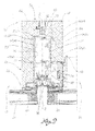
- figure 1 shows a schematic front view of a modular structural facade according to one embodiment of the present invention
- figure 2 shows a cross-section view of the facade in figure 1 , along the section plane II-II of figure 1 ;
- figure 3 shows a schematic view of an industrialised production method of a structural facade according to the present invention
- reference numeral 4 globally denotes a structural facade or a portion of a structural facade, for buildings and the like, comprising a plurality of cells 8.
- the cells 8 are usually attached to the load-bearing structure of the building so as to make the external facade.
- the cells are a quadrangular, rectangular or square shaped and each comprises a pair of uprights 12 and a pair of crossbeams 16.
- the uprights 12 and the crossbeams 16 are preferably perpendicular to each other.
- Adjacent cells 8', 8" are positioned alongside each other at adjacent uprights 12', 12" or crossbeams 16', 16".
- the cell 8 comprises a structural frame having a pair of uprights 12 and a pair of crossbeams 16 so as to form a structure closed around the perimeter delimiting a perimetral compartment 20 suitable to be closed by external glazing 24 mechanically associated to the frame on an anterior face 28 of the latter.
- the anterior face 28 of the frame of the cell 8 is destined to be positioned on the outside of the building so as to constitute the facade itself.
- the external glazing 24, depending on the type of cell, may be fixed, openable, visual, blind.
- it may comprise a glass pane or even an opaque panel, in any material.
- the uprights 12 and the crossbeams 16 comprise a load-bearing metallic core 32 which supports and lends structural rigidity to the cell.
- the metallic core 32 comprises means of attachment 36, for the support and attachment of the glazing 24 to the structural frame, the means of attachment 36 being positioned on the side opposite the perimetral compartment 20.
- the means of attachment 36 comprise screws, pins, wall plugs and similar.
- the glazing 24 is attached with gluing and structural sealing to a small support frame 40; said small support frame 40 being attached on the anterior face 28 of the metallic core 32 by said means of attachment 36.
- the means of attachment block the glazing 24, by means of the small support frame 40, directly onto the metallic core 32 of the cell 8.
- the uprights 12 and the crossbeams 16 each comprise at least one cheek panel 44, directly facing said perimetral compartment 20, on the side opposite the means of attachment 36 of the external glazing 24.
- the cheek panel 44 is preferably in wood; a non-metallic material may also be envisaged having insulation properties and good fire-resistance so as to protect the metallic core which it covers.
- the cheek panel 44 covers the metallic core 32 on the side of the perimetral compartment 20, at a lateral rim 48 of the perimetral compartment 20, and also covers it from the inner side 52 at the rear face 56 of the frame, opposite the associable glazing 24 and the anterior face 28, so as to increase the resistance to fire, as well as the heat and noise insulation of the cell 8.
- the cheek panel 44 is bound to the metallic core 32 of the crossbeams 16 and of the uprights 12 by means of shaped couplings 60 and/or gluing means 64.
- the shaped coupling means 60 comprise joints between at least one protuberance 68 made preferably on the metallic core 32 and at least one groove 72, counter-shaped to the protuberance 68, made preferably on an inner face 76 of the cheek panel 44, directly facing the metallic core 32.
- the protuberance 68 and the groove 72 can also be positioned in an inverted manner, that is the protuberance can be positioned on an inner portion of the cheek panel 44 and the groove 72 can be made on the metallic core 32.
- the protuberance 68 and the groove 72 have a main longitudinal extension, in a vertical direction Y-Y for the uprights 12 and in a horizontal direction X-X for the crossbeams 16, so as to bind the metallic cores 32 and cheek panels 44 to each other in a transversal direction Z-Z, perpendicular to the horizontal X-X and vertical Y-Y direction, and so as to enable relative sliding between the metallic cores 32 and the cheek panels 44 parallel to said respective horizontal X-X and vertical Y-Y directions.
- the shaped coupling means 60 enable easy alignment of the profiles of the uprights 12 and of the crossbeams 16, as well as enabling the wood to collaborate structurally with the metal, preferably aluminium, improving the final inertia of the cell 8. Moreover, said shaped coupling means 60 make it possible to prevent the coupling from becoming purely structural as a result of the resulting complexity of identifying a sealing agent which assures tightness, given the complex nature of wood and its behaviour. In other words, said shaped coupling means, as mentioned above, permit relative sliding between the metallic core 32 and the cheek panel 44.
- a chamber 80 containing said gluing means 64 able to glue and seal the cheek panel 44 and metallic core 32 to each other is defined.
- said chamber 80 has a constant predefined thickness and the gluing means 64 have a higher elasticity modulus than the materials of the cheek panel 44 and the metallic core 32 so as to allow and absorb the different dilations of the two coupled materials.
- the protuberance 68 has a wider part 84 at the portion of attachment to the metallic core 32 so as to identify a limit stop to the insertion of the protuberance 68 in the groove 72 and guarantee the presence of a chamber 80 for the containment of the gluing means 64.
- the gluing means 64 have a temperature resistance of up to 200°, so as to ensure the mechanical connection of the cheek panels 44 and the metallic core 32 of the frame, up to the structural resistance limit of the metallic frame.
- the cells 8 are positioned alongside each other both in a horizontal direction X-X, by drawing together and joining respective adjacent uprights 12', 12" to each other and in a vertical direction Y-Y by drawing together and joining respective adjacent crossbeams 16', 16" to each other.
- the mechanical connection of the uprights 12', 12" and the crossbeams 16', 16" is performed by means of joints 88 fitted with undercuts in an axial direction Z-Z perpendicular to the associable glazing, and perpendicular to the horizontal direction X-X and the vertical direction Y-Y.
- intumescent tapes 92 are inserted to improve the resistance to fire of the facade 4.
- said intumescent tapes 92 are used to protect the zones most at risk of sparking a flame, such as corners, untreated or more exposed parts of the cell 8.
- the cells according to the present invention are supplied in an assembly kit.
- the kit comprises at least one pair of uprights 12 and a pair of crossbeams 16 each comprising a load-bearing metallic core 32, comprising means of attachment 36 of the external glazing 24, and at least one cheek panel 44 in wood, opposite said means of attachment 36.
- the cheek panel 44 is preassembled to the respective metallic core 32 by means of shaped couplings 60 and/or gluing means 64.
- the shaped coupling means 60 comprise joints between at least one protuberance 68 made on the core and at least one groove 72, counter-shaped to the protuberance 68, made on an inner face 76 of the cheek panel 44, directly facing the metallic core 32.
- the preassembly envisages that between an inner face 76 of the cheek panel 44, directly facing the metallic core 32 and the metallic core 32 itself, a chamber 80 containing said gluing means 64 able to glue and seal the cheek panel 44 and metallic core 32 to each other is defined.
- the kit envisages that the uprights and the crossbeams are preassembled so as to associate each cheek panel 44 to the respective metallic core 32.
- the uprights 16 and the crossbeams 12 are shaped so as to form, in an assembled configuration, a structure closed around the perimeter which delimits a perimetral compartment 20 suitable for being closed by the external glazing 24 mechanically associated to the frame on an anterior face 28 of the latter.
- the method of making and installing a structural facade 4 composed of cells 8 comprises the initial steps of cutting to size and supplying metallic cores 32 and relative cheek panels 44 for uprights 12 and crossbeams 16 of at least one cell 8 ( figure3 , step A).
- any surface treatments of the cheek panels such as for example varnishing, smoothing and surface finishing 8 figure 3 , step B) are performed.
- the step of preassembling at least one pair of uprights 12 and one pair of crossbeams 16 each comprising a load-bearing metallic core 32, comprising means of attachment 36 of the external glazing 24, and at least one cheek panel 44 in wood, opposite said means of attachment 36 takes place; the cheek panel 44 is preassembled to the core 32 by means of shaped couplings 60 and/or gluing means 64.
- the gluing or sealing agent is distributed in the chamber between the metallic core 32 and the cheek panel 44 and then the panel and the core are assembled by means of the shaped coupling between the protuberance 68 and the groove 72 ( figure 3 , step C).
- the method may comprise the creation of an assembly kit comprising the metallic cores of the uprights 12 and of the crossbeams 16 preassembled to the respective cheek panels 44 so as to permit subsequent assembly to each other to form a cell to insert in a structural wall 4 ( figure 3 , step D).
- the method may rather comprise the step of immediately assembling the crossbeams 16 and the uprights 12 so as to form a structure closed around the perimeter delimiting a perimetral compartment 20 and closing the perimetral compartment 20 by external glazing 24 mechanically associated to the frame on an anterior face 28 of the latter ( figure 3 , step E).
- the glazing 24 is attached with gluing and structural sealing to a small support frame 40, said small support frame 40 being attached on an anterior face 28 of said metallic core 32 by said means of attachment 36.
- the present invention makes it possible to overcome the drawbacks presented in relation to the prior art.
- the present invention permits an improvement of the heat insulation performance for improved comfort of the surroundings.
- the present invention permits an improvement of noise reduction, increasing the mass of the joints between adjacent cells.
- the shaped coupling and the gluing of the metallic cores and the cheek panels makes it possible to make the wood collaborate structurally with the aluminium, improving that is to say increasing, the final inertia of the structure.
- the coupling of the metallic core and the relative cheek is not of a purely structural type, that is does not guarantee the same rigidity given for example by nuts and bolts which join said elements to each other in a rigid manner.
- a structural type connection would create high tension between the two materials having different deformations depending on the environmental conditions of temperature but also of humidity.
Landscapes
- Engineering & Computer Science (AREA)
- Architecture (AREA)
- Physics & Mathematics (AREA)
- Electromagnetism (AREA)
- Civil Engineering (AREA)
- Structural Engineering (AREA)
- Load-Bearing And Curtain Walls (AREA)
- Hybrid Cells (AREA)
Abstract
Description
- The present invention relates to a modular structural facade and an assembly kit of a modular structural facade.
- In particular, it is known in the art to make structural facades from modular panels, called "cells", preassembled in the assembly plant and then installed on site.
- The cells are attached to a load-bearing structure of the building. This means that by means of horizontal and vertical dilation joints, each cell is independent of the others both as regards its own dilation and in relation to settlement or seismic movements of the building itself, thereby preventing breakage of the elements composing it (glass panes, aluminium).
- The cell is normally composed of a perimetral, metal structure and of infill panels. The perimetral structure is usually in aluminium and the infill panels can be visual glazing, blind glazing with insulation panel, in aluminium, marble etc.
- The infill panels of the visual parts may be fixed or openable, according to the user's needs.
- The cells of the prior art have a number of drawbacks and disadvantages.
- For example, while the external aesthetics of the cells maintain the typical appearance of structural facades, the internal appearance of the cells, in other words from the inside of the structure or building, has visible metal portions not always to the user's liking.
- Moreover, the performance in terms of heat and noise insulation of the structural facades of the prior art are not optimal or in line with the increasingly rigid demands of the market as regards international energy parameters.
- Moreover, the structural facades of the prior art are not particularly fire-resistant.
- The present invention therefore sets out to resolve the drawbacks mentioned with reference to the prior art.
- Such limitations and drawbacks are resolved by a structural facade according to claim 1, by an assembly kit according to claim 10.
- Other embodiments of the present invention are described in the further claims.
- Further characteristics and advantages of the present invention will be more clearly comprehensible from the description given below of its preferred and non-limiting embodiments, wherein
-
figure 1 shows a schematic front view of a modular structural facade according to one embodiment of the present invention; -
figure 2 shows a cross-section view of the facade infigure 1 , along the section plane II-II offigure 1 ; -
figure 3 shows a schematic view of an industrialised production method of a structural facade according to the present invention; - The element or parts of elements common to the embodiments described below will be indicated using the same reference numerals.
- With reference to the aforementioned figures, reference numeral 4 globally denotes a structural facade or a portion of a structural facade, for buildings and the like, comprising a plurality of
cells 8. Thecells 8 are usually attached to the load-bearing structure of the building so as to make the external facade. - For example, the cells are a quadrangular, rectangular or square shaped and each comprises a pair of
uprights 12 and a pair of crossbeams 16. Theuprights 12 and the crossbeams 16 are preferably perpendicular to each other.Adjacent cells 8', 8" are positioned alongside each other atadjacent uprights 12', 12" or crossbeams 16', 16". - The
cell 8 comprises a structural frame having a pair ofuprights 12 and a pair of crossbeams 16 so as to form a structure closed around the perimeter delimiting aperimetral compartment 20 suitable to be closed byexternal glazing 24 mechanically associated to the frame on ananterior face 28 of the latter. - The
anterior face 28 of the frame of thecell 8 is destined to be positioned on the outside of the building so as to constitute the facade itself. - The
external glazing 24, depending on the type of cell, may be fixed, openable, visual, blind. For example it may comprise a glass pane or even an opaque panel, in any material. - Advantageously, the
uprights 12 and the crossbeams 16 comprise a load-bearingmetallic core 32 which supports and lends structural rigidity to the cell. - The
metallic core 32 comprises means ofattachment 36, for the support and attachment of theglazing 24 to the structural frame, the means ofattachment 36 being positioned on the side opposite theperimetral compartment 20. - For example, the means of
attachment 36 comprise screws, pins, wall plugs and similar. - According to one embodiment, the
glazing 24 is attached with gluing and structural sealing to a small support frame 40; said small support frame 40 being attached on theanterior face 28 of themetallic core 32 by said means ofattachment 36. In other words, the means of attachment block theglazing 24, by means of the small support frame 40, directly onto themetallic core 32 of thecell 8. - Advantageously, the
uprights 12 and the crossbeams 16 each comprise at least onecheek panel 44, directly facing saidperimetral compartment 20, on the side opposite the means ofattachment 36 of theexternal glazing 24. Thecheek panel 44 is preferably in wood; a non-metallic material may also be envisaged having insulation properties and good fire-resistance so as to protect the metallic core which it covers. - The
cheek panel 44 covers themetallic core 32 on the side of theperimetral compartment 20, at alateral rim 48 of theperimetral compartment 20, and also covers it from theinner side 52 at therear face 56 of the frame, opposite theassociable glazing 24 and theanterior face 28, so as to increase the resistance to fire, as well as the heat and noise insulation of thecell 8. - The
cheek panel 44 is bound to themetallic core 32 of the crossbeams 16 and of theuprights 12 by means of shaped couplings 60 and/or gluing means 64. - According to one embodiment, the shaped coupling means 60 comprise joints between at least one protuberance 68 made preferably on the
metallic core 32 and at least onegroove 72, counter-shaped to the protuberance 68, made preferably on aninner face 76 of thecheek panel 44, directly facing themetallic core 32. - The protuberance 68 and the
groove 72 can also be positioned in an inverted manner, that is the protuberance can be positioned on an inner portion of thecheek panel 44 and thegroove 72 can be made on themetallic core 32. - Preferably, the protuberance 68 and the
groove 72 have a main longitudinal extension, in a vertical direction Y-Y for theuprights 12 and in a horizontal direction X-X for the crossbeams 16, so as to bind themetallic cores 32 andcheek panels 44 to each other in a transversal direction Z-Z, perpendicular to the horizontal X-X and vertical Y-Y direction, and so as to enable relative sliding between themetallic cores 32 and thecheek panels 44 parallel to said respective horizontal X-X and vertical Y-Y directions. - The shaped coupling means 60 enable easy alignment of the profiles of the
uprights 12 and of the crossbeams 16, as well as enabling the wood to collaborate structurally with the metal, preferably aluminium, improving the final inertia of thecell 8. Moreover, said shaped coupling means 60 make it possible to prevent the coupling from becoming purely structural as a result of the resulting complexity of identifying a sealing agent which assures tightness, given the complex nature of wood and its behaviour. In other words, said shaped coupling means, as mentioned above, permit relative sliding between themetallic core 32 and thecheek panel 44. - Preferably, between an
inner face 76 of thecheek panel 44, directly facing themetallic core 32 and themetallic core 32 itself, a chamber 80 containing said gluing means 64 able to glue and seal thecheek panel 44 andmetallic core 32 to each other is defined. - According to one embodiment, said chamber 80 has a constant predefined thickness and the gluing means 64 have a higher elasticity modulus than the materials of the
cheek panel 44 and themetallic core 32 so as to allow and absorb the different dilations of the two coupled materials. - According to one possible embodiment, the protuberance 68 has a
wider part 84 at the portion of attachment to themetallic core 32 so as to identify a limit stop to the insertion of the protuberance 68 in thegroove 72 and guarantee the presence of a chamber 80 for the containment of the gluing means 64. - Preferably, the gluing means 64 have a temperature resistance of up to 200°, so as to ensure the mechanical connection of the
cheek panels 44 and themetallic core 32 of the frame, up to the structural resistance limit of the metallic frame. - As mentioned above, the
cells 8 are positioned alongside each other both in a horizontal direction X-X, by drawing together and joining respectiveadjacent uprights 12', 12" to each other and in a vertical direction Y-Y by drawing together and joining respective adjacent crossbeams 16', 16" to each other. - The mechanical connection of the
uprights 12', 12" and the crossbeams 16', 16" is performed by means ofjoints 88 fitted with undercuts in an axial direction Z-Z perpendicular to the associable glazing, and perpendicular to the horizontal direction X-X and the vertical direction Y-Y. - Preferably, at the connections between the
uprights 12 and/or the crossbeams 16 ofcells 8 adjacent to each other,intumescent tapes 92 are inserted to improve the resistance to fire of the facade 4. In particular, saidintumescent tapes 92 are used to protect the zones most at risk of sparking a flame, such as corners, untreated or more exposed parts of thecell 8. - According to one embodiment, the cells according to the present invention are supplied in an assembly kit.
- The kit comprises at least one pair of
uprights 12 and a pair of crossbeams 16 each comprising a load-bearingmetallic core 32, comprising means ofattachment 36 of theexternal glazing 24, and at least onecheek panel 44 in wood, opposite said means ofattachment 36. In particular, inside the assembly kit thecheek panel 44 is preassembled to the respectivemetallic core 32 by means of shaped couplings 60 and/or gluing means 64. - The shaped coupling means 60 comprise joints between at least one protuberance 68 made on the core and at least one
groove 72, counter-shaped to the protuberance 68, made on aninner face 76 of thecheek panel 44, directly facing themetallic core 32. - Moreover, the preassembly envisages that between an
inner face 76 of thecheek panel 44, directly facing themetallic core 32 and themetallic core 32 itself, a chamber 80 containing said gluing means 64 able to glue and seal thecheek panel 44 andmetallic core 32 to each other is defined. - As a result, the kit envisages that the uprights and the crossbeams are preassembled so as to associate each
cheek panel 44 to the respectivemetallic core 32. - Moreover, the uprights 16 and the
crossbeams 12 are shaped so as to form, in an assembled configuration, a structure closed around the perimeter which delimits aperimetral compartment 20 suitable for being closed by theexternal glazing 24 mechanically associated to the frame on ananterior face 28 of the latter. - The method of making and installing a cell and a structural facade according to the invention will now be described.
- In particular, The method of making and installing a structural facade 4 composed of
cells 8 according to the invention comprises the initial steps of cutting to size and supplyingmetallic cores 32 andrelative cheek panels 44 foruprights 12 and crossbeams 16 of at least one cell 8 (figure3 , step A). - Then any surface treatments of the cheek panels, such as for example varnishing, smoothing and surface finishing 8
figure 3 , step B) are performed. - Then the step of preassembling at least one pair of
uprights 12 and one pair of crossbeams 16 each comprising a load-bearingmetallic core 32, comprising means ofattachment 36 of theexternal glazing 24, and at least onecheek panel 44 in wood, opposite said means ofattachment 36 takes place; thecheek panel 44 is preassembled to thecore 32 by means of shaped couplings 60 and/or gluing means 64. - In particular, first the gluing or sealing agent is distributed in the chamber between the
metallic core 32 and thecheek panel 44 and then the panel and the core are assembled by means of the shaped coupling between the protuberance 68 and the groove 72 (figure 3 , step C). - The method may comprise the creation of an assembly kit comprising the metallic cores of the
uprights 12 and of the crossbeams 16 preassembled to therespective cheek panels 44 so as to permit subsequent assembly to each other to form a cell to insert in a structural wall 4 (figure 3 , step D). - The method may rather comprise the step of immediately assembling the crossbeams 16 and the
uprights 12 so as to form a structure closed around the perimeter delimiting aperimetral compartment 20 and closing theperimetral compartment 20 byexternal glazing 24 mechanically associated to the frame on ananterior face 28 of the latter (figure 3 , step E). - For example, the
glazing 24 is attached with gluing and structural sealing to a small support frame 40, said small support frame 40 being attached on ananterior face 28 of saidmetallic core 32 by said means ofattachment 36. - As may be seen from the description, the present invention makes it possible to overcome the drawbacks presented in relation to the prior art.
- In particular, it permits an improvement of the final internal appearance of the facade, while maintaining unaltered the glazed exterior typical of the structural facade, comprising visible external metallic elements.
- Moreover, the present invention permits an improvement of the heat insulation performance for improved comfort of the surroundings.
- Moreover, the present invention permits an improvement of noise reduction, increasing the mass of the joints between adjacent cells.
- Moreover, the presence of the wood cheek permits a considerable improvement of the fire resistance of the cells and therefore of the facade itself.
- The shaped coupling and the gluing of the metallic cores and the cheek panels makes it possible to make the wood collaborate structurally with the aluminium, improving that is to say increasing, the final inertia of the structure. In other words, the coupling of the metallic core and the relative cheek is not of a purely structural type, that is does not guarantee the same rigidity given for example by nuts and bolts which join said elements to each other in a rigid manner. In fact, a structural type connection would create high tension between the two materials having different deformations depending on the environmental conditions of temperature but also of humidity.
- The use of shaped coupling means and gluing means rather allows both different deformations of the elements, without creating excessive tension on the same, and also an increase in the mass and overall inertia of the uprights and the crossbeams, so as to improve the heat and noise insulation of the structure.
- A person skilled in the art may make numerous modifications and variations to the facades described above so as to satisfy contingent and specific requirements, while remaining within the sphere of protection of the invention as defined by the following claims.
Claims (12)
- Structural facade (4) comprising at least two cells (8) for buildings and the like, comprising- a structural frame having a pair of uprights (12) and a pair of crossbeams (16) so as to form a structure closed around the perimeter delimiting a perimetral compartment (20), the perimetral compartment (20) being suitable to be closed by external glazing (24) mechanically associated to the frame on an anterior face (28) of the latter,
wherein- said uprights (12) and crossbeams (16) comprise a load-bearing metallic core (32) which supports and lends structural rigidity to the cell (8),- the metallic core (32) comprises means of attachment (36), such as screws, pins, wall plugs and similar, for the support and attachment of the external glazing (24) to the structural frame, the means of attachment (36) being positioned on the side opposite the perimetral compartment (20),- said uprights (12) and crossbeams (16) each comprising at least one cheek panel (44) in wood, directly facing said perimetral compartment (20), on the side opposite the means of attachment (36) of the external glazing (24),- the cheek panel (44) being bound to the metallic core (32) of the crossbeams (16) and of the uprights (12) by means of shaped couplings (60) and/or gluing means(64),- the cheek panel (44) covering the metallic core (32) on the side of the perimetral compartment (20) and on a rear face (56) of the frame, opposite the associable glazing (24), so as to increase the resistance to fire of the system, as well as the heat and noise insulation characterised by the fact that
the cells (8) are placed alongside at their respective uprights (12) and/or crossbeams (16) adjacent to each other and connected to each other by joints (88) fitted with undercuts in an axial direction (Z-Z) perpendicular to the associable glazing (24). - Structural facade (4) according to claim 1, wherein the shaped coupling means (60) comprise joints between at least one protuberance (58) made on the metallic core (32) and at least one groove (72), counter-shaped to the protuberance (68), made on an inner face (76) of the cheek panel (44), directly facing the metallic core (32).
- Structural facade (4) according to claim 2, wherein the protuberance (68) and the groove (72) have a main longitudinal extension, in a vertical direction (Y-Y) for the uprights (12) and in a horizontal direction (X-X) for the crossbeams (16), so as to bind the metallic cores (32) and cheek panels (44) to each other in a transversal direction (Z-Z), perpendicular to the horizontal (X-X) and vertical (Y-Y) direction, and so as to enable relative sliding between the metallic cores (32) and the cheek panels (44) parallel to said respective horizontal (X-X) and vertical (Y-Y) directions.
- Structural facade (4) according to claim 1, 2 or 3, wherein between an inner face (76) of the cheek panel (44), directly facing the metallic core (32)and the metallic core itself, a chamber (80) containing said gluing means (64) able to glue and seal the cheek panel (44) and metallic core (32) to each other is defined.
- Structural facade (4) according to claim 4, wherein said chamber (80) has a constant predefined thickness and the gluing means (64) have a higher elasticity modulus than the materials of the cheek panel (44) and the metallic core (32) so as to allow and absorb the different dilations of the two coupled materials.
- Structural facade (4) according to any of the claims from 2 to 5, wherein the protuberance (68) has a wider part (84) at the portion of attachment to the metallic core (32) so as to identify a limit stop to the insertion of the protuberance (68) in the groove (72) and guarantee the presence of a chamber (80) for the containment of the gluing means (64).
- Structural facade (4) according to any of the previous claims, wherein the gluing means (64) have a temperature resistance of up to 200°, so as to ensure the mechanical connection of the cheek panels (44) and the frame up to the structural resistance limit of the metallic frame.
- Structural facade (4) according to any of the previous claims, wherein the glazing (24) is attached with gluing and structural sealing to a small support frame (40), said small support frame (40) being attached on a front face (28) of said metallic core (32) by said means of attachment (36).
- Structural facade (4) according to claim 8, wherein, at the point of the connections between the uprights (12) and/or the crossbeams (16) of cells (8) adjacent to each other, intumescent tapes (92) are inserted to improve the resistance to fire of the facade.
- Assembly kit of a cell (8) of a structural facade (4) of cells according to any of the previous claims, the kit comprising
at least a pair of uprights (12) and a pair of crossbeams (16) each comprising a load-bearing metallic core (32), comprising means of attachment (36) of the external glazing (24), and at least one cheek panel (44) in wood, opposite said means of attachment (36),- - the cheek panel (44) being preassembled to the metallic core (32) by means of shaped couplings (60) and/or gluing means 64),- the uprights (16) and the crossbeams (12) being shaped so as to form, in an assembled configuration, a structure closed around the perimeter which delimits a perimetral compartment (20), the perimetral compartment (20) being suitable for closing by the external glazing (24) mechanically associated to the frame on an anterior face (28) of the latter. - Kit according to claim 10, wherein the shaped coupling means (60) comprise joints between at least one protuberance (68) made on the metallic core (32) and at least one groove (72), counter-shaped to the protuberance (68), made on an inner face (76) of the cheek panel (44), directly facing the metallic core (32), wherein the protuberance (68) and the groove (72) have a main longitudinal extension, substantially parallel to the respective uprights (12) and crossbeams (16), so as to bind the cores (32) and the cheeks (44) to each other in a transversal direction (Z-Z), perpendicular to the horizontal (X-X) and vertical (Y-Y) direction, and so as to enable relative sliding between the cores (32) and the cheeks (44) parallel to said horizontal (X-X) and vertical (Y-Y) directions.
- Kit according to claim 10 or 11, wherein between an inner face (76) of the cheek panel (44), directly facing the metallic core (32) and the metallic core (32) itself, there is a chamber (80) containing said gluing means (64) which glue and seal the cheek panel (44) and metallic core (32) to each other.
Applications Claiming Priority (1)
| Application Number | Priority Date | Filing Date | Title |
|---|---|---|---|
| ITPD2010A000316A IT1402781B1 (en) | 2010-10-20 | 2010-10-20 | CELL STRUCTURAL FACADE CELL, ASSEMBLY OF A CELL OF A CELL STRUCTURAL FACADE AND METHOD OF ASSEMBLING A CELL OF A STRUCTURAL CELL FACADE |
Publications (2)
| Publication Number | Publication Date |
|---|---|
| EP2444565A1 true EP2444565A1 (en) | 2012-04-25 |
| EP2444565B1 EP2444565B1 (en) | 2015-11-11 |
Family
ID=43738214
Family Applications (1)
| Application Number | Title | Priority Date | Filing Date |
|---|---|---|---|
| EP11182805.9A Not-in-force EP2444565B1 (en) | 2010-10-20 | 2011-09-26 | Modular structural facade |
Country Status (2)
| Country | Link |
|---|---|
| EP (1) | EP2444565B1 (en) |
| IT (1) | IT1402781B1 (en) |
Cited By (3)
| Publication number | Priority date | Publication date | Assignee | Title |
|---|---|---|---|---|
| EP3480383A1 (en) * | 2017-11-06 | 2019-05-08 | Giugiaro Architettura & Structures S.r.l. | System for closing openings in buildings and building structures in general, and corresponding covering kit |
| DE102023109239A1 (en) * | 2023-04-12 | 2024-10-17 | SCHÜCO International KG | element facade |
| WO2025177227A1 (en) * | 2024-02-23 | 2025-08-28 | Wood Beton S.P.A. | Prefabricated group for the exterior facade of a building, prefabricated exterior wall or facade and prefabricated module |
Families Citing this family (1)
| Publication number | Priority date | Publication date | Assignee | Title |
|---|---|---|---|---|
| CN113266094A (en) * | 2021-05-14 | 2021-08-17 | 安徽建筑大学 | Adjustable connecting node and assembly type structure |
Citations (4)
| Publication number | Priority date | Publication date | Assignee | Title |
|---|---|---|---|---|
| EP0436868A2 (en) * | 1990-01-12 | 1991-07-17 | Reynolds Aluminium Deutschland, Internationale Vertriebsgesellschaft Mbh | Supporting structure for a façade wall |
| DE9409420U1 (en) * | 1994-06-10 | 1994-08-04 | Ritter Ingenieurfassaden GmbH, 73257 Köngen | Wood-aluminum windows |
| DE10307834A1 (en) * | 2002-03-08 | 2003-10-02 | Fischl Joseph | Profile material for producing frames for building windows and/or French doors involves cutting material to length required for frame components and then connecting components together |
| DE202004018830U1 (en) * | 2004-12-06 | 2005-02-10 | Schindler Gmbh & Co. Fenster-Fassaden-Innenausbau Kg | Attachment construction for wood-post-beam components forming facade structures is of metal, preferably aluminium, or very strong plastic and is divided |
-
2010
- 2010-10-20 IT ITPD2010A000316A patent/IT1402781B1/en active
-
2011
- 2011-09-26 EP EP11182805.9A patent/EP2444565B1/en not_active Not-in-force
Patent Citations (4)
| Publication number | Priority date | Publication date | Assignee | Title |
|---|---|---|---|---|
| EP0436868A2 (en) * | 1990-01-12 | 1991-07-17 | Reynolds Aluminium Deutschland, Internationale Vertriebsgesellschaft Mbh | Supporting structure for a façade wall |
| DE9409420U1 (en) * | 1994-06-10 | 1994-08-04 | Ritter Ingenieurfassaden GmbH, 73257 Köngen | Wood-aluminum windows |
| DE10307834A1 (en) * | 2002-03-08 | 2003-10-02 | Fischl Joseph | Profile material for producing frames for building windows and/or French doors involves cutting material to length required for frame components and then connecting components together |
| DE202004018830U1 (en) * | 2004-12-06 | 2005-02-10 | Schindler Gmbh & Co. Fenster-Fassaden-Innenausbau Kg | Attachment construction for wood-post-beam components forming facade structures is of metal, preferably aluminium, or very strong plastic and is divided |
Cited By (5)
| Publication number | Priority date | Publication date | Assignee | Title |
|---|---|---|---|---|
| EP3480383A1 (en) * | 2017-11-06 | 2019-05-08 | Giugiaro Architettura & Structures S.r.l. | System for closing openings in buildings and building structures in general, and corresponding covering kit |
| US10731340B2 (en) | 2017-11-06 | 2020-08-04 | Giugiaro Architettura & Structures S.r.l. | System for closing openings in buildings and building structures in general, and corresponding covering kit |
| DE102023109239A1 (en) * | 2023-04-12 | 2024-10-17 | SCHÜCO International KG | element facade |
| EP4450729A1 (en) | 2023-04-12 | 2024-10-23 | SCHÜCO International KG | Unit type curtain wall |
| WO2025177227A1 (en) * | 2024-02-23 | 2025-08-28 | Wood Beton S.P.A. | Prefabricated group for the exterior facade of a building, prefabricated exterior wall or facade and prefabricated module |
Also Published As
| Publication number | Publication date |
|---|---|
| EP2444565B1 (en) | 2015-11-11 |
| IT1402781B1 (en) | 2013-09-18 |
| ITPD20100316A1 (en) | 2012-04-21 |
Similar Documents
| Publication | Publication Date | Title |
|---|---|---|
| CA2344071A1 (en) | Fire wall | |
| EP2444565B1 (en) | Modular structural facade | |
| CN217053937U (en) | Curtain wall unit capable of hiding keel and unitized curtain wall system | |
| CN104769195B (en) | Combined wall body and construction method thereof | |
| CN208379873U (en) | A kind of unit fireproof curtain wall | |
| CN109930944B (en) | Mounting method of hidden auxiliary sleeve | |
| CN212296138U (en) | Decorative fireproof door frame | |
| CN120139416A (en) | A hidden aluminum curtain wall ultra-thin composite vacuum insulation ventilation opening system and construction method thereof | |
| CN211499334U (en) | Novel glass panel curtain wall without transverse frame | |
| CN106285380A (en) | The T-shaped timber that a kind of sound insulaton is effective | |
| CN207568448U (en) | Artificial board decorative steel skeleton high-strength fire-retardant door leaf | |
| CN206000408U (en) | A kind of good T-shaped timber of sound insulaton effect | |
| CN212054397U (en) | Split fireproof profiles and corresponding embedded aluminum clad steel fireproof windows | |
| CN212296137U (en) | Fireproof door leaf | |
| CN214035284U (en) | Semi-hidden frame window sash mounting structure of opening | |
| CN205277223U (en) | Fire door is prevented to wooden lacquer of exempting from | |
| CN211692151U (en) | Fireproof door pocket and fireproof suit door using same | |
| CN210421550U (en) | Partition wall closing structure that meets the glass frame supporting the glass curtain wall | |
| CN219060493U (en) | Curtain wall moulding mounting structure of large-scale fire-fighting linkage smoke exhaust system | |
| CN111255353A (en) | Split type fireproof section bar and corresponding embedded aluminum-clad steel fireproof window | |
| CN221030968U (en) | Assembled composite board structure | |
| KR200326568Y1 (en) | Complex windows and doors having inner panel and outer panel assembled by inserting type | |
| CN210508934U (en) | A installation window for passive room | |
| CN215949297U (en) | Steel fireproof door with rear-mounted glass window | |
| CN219471298U (en) | Combined type curtain decorative board convenient to equipment |
Legal Events
| Date | Code | Title | Description |
|---|---|---|---|
| 17P | Request for examination filed |
Effective date: 20110926 |
|
| AK | Designated contracting states |
Kind code of ref document: A1 Designated state(s): AL AT BE BG CH CY CZ DE DK EE ES FI FR GB GR HR HU IE IS IT LI LT LU LV MC MK MT NL NO PL PT RO RS SE SI SK SM TR |
|
| AX | Request for extension of the european patent |
Extension state: BA ME |
|
| PUAI | Public reference made under article 153(3) epc to a published international application that has entered the european phase |
Free format text: ORIGINAL CODE: 0009012 |
|
| 17Q | First examination report despatched |
Effective date: 20140228 |
|
| GRAP | Despatch of communication of intention to grant a patent |
Free format text: ORIGINAL CODE: EPIDOSNIGR1 |
|
| INTG | Intention to grant announced |
Effective date: 20150602 |
|
| GRAS | Grant fee paid |
Free format text: ORIGINAL CODE: EPIDOSNIGR3 |
|
| GRAA | (expected) grant |
Free format text: ORIGINAL CODE: 0009210 |
|
| AK | Designated contracting states |
Kind code of ref document: B1 Designated state(s): AL AT BE BG CH CY CZ DE DK EE ES FI FR GB GR HR HU IE IS IT LI LT LU LV MC MK MT NL NO PL PT RO RS SE SI SK SM TR |
|
| REG | Reference to a national code |
Ref country code: GB Ref legal event code: FG4D |
|
| REG | Reference to a national code |
Ref country code: CH Ref legal event code: EP |
|
| REG | Reference to a national code |
Ref country code: IE Ref legal event code: FG4D |
|
| REG | Reference to a national code |
Ref country code: AT Ref legal event code: REF Ref document number: 760544 Country of ref document: AT Kind code of ref document: T Effective date: 20151215 |
|
| REG | Reference to a national code |
Ref country code: DE Ref legal event code: R096 Ref document number: 602011021336 Country of ref document: DE |
|
| REG | Reference to a national code |
Ref country code: CH Ref legal event code: NV Representative=s name: JACOBACCI AND PARTNERS SA, CH |
|
| REG | Reference to a national code |
Ref country code: LT Ref legal event code: MG4D |
|
| REG | Reference to a national code |
Ref country code: NL Ref legal event code: MP Effective date: 20160211 |
|
| REG | Reference to a national code |
Ref country code: AT Ref legal event code: MK05 Ref document number: 760544 Country of ref document: AT Kind code of ref document: T Effective date: 20151111 |
|
| PG25 | Lapsed in a contracting state [announced via postgrant information from national office to epo] |
Ref country code: ES Free format text: LAPSE BECAUSE OF FAILURE TO SUBMIT A TRANSLATION OF THE DESCRIPTION OR TO PAY THE FEE WITHIN THE PRESCRIBED TIME-LIMIT Effective date: 20151111 Ref country code: LT Free format text: LAPSE BECAUSE OF FAILURE TO SUBMIT A TRANSLATION OF THE DESCRIPTION OR TO PAY THE FEE WITHIN THE PRESCRIBED TIME-LIMIT Effective date: 20151111 Ref country code: NO Free format text: LAPSE BECAUSE OF FAILURE TO SUBMIT A TRANSLATION OF THE DESCRIPTION OR TO PAY THE FEE WITHIN THE PRESCRIBED TIME-LIMIT Effective date: 20160211 Ref country code: NL Free format text: LAPSE BECAUSE OF FAILURE TO SUBMIT A TRANSLATION OF THE DESCRIPTION OR TO PAY THE FEE WITHIN THE PRESCRIBED TIME-LIMIT Effective date: 20151111 Ref country code: IS Free format text: LAPSE BECAUSE OF FAILURE TO SUBMIT A TRANSLATION OF THE DESCRIPTION OR TO PAY THE FEE WITHIN THE PRESCRIBED TIME-LIMIT Effective date: 20160311 Ref country code: HR Free format text: LAPSE BECAUSE OF FAILURE TO SUBMIT A TRANSLATION OF THE DESCRIPTION OR TO PAY THE FEE WITHIN THE PRESCRIBED TIME-LIMIT Effective date: 20151111 |
|
| PG25 | Lapsed in a contracting state [announced via postgrant information from national office to epo] |
Ref country code: GR Free format text: LAPSE BECAUSE OF FAILURE TO SUBMIT A TRANSLATION OF THE DESCRIPTION OR TO PAY THE FEE WITHIN THE PRESCRIBED TIME-LIMIT Effective date: 20160212 Ref country code: PT Free format text: LAPSE BECAUSE OF FAILURE TO SUBMIT A TRANSLATION OF THE DESCRIPTION OR TO PAY THE FEE WITHIN THE PRESCRIBED TIME-LIMIT Effective date: 20160311 Ref country code: RS Free format text: LAPSE BECAUSE OF FAILURE TO SUBMIT A TRANSLATION OF THE DESCRIPTION OR TO PAY THE FEE WITHIN THE PRESCRIBED TIME-LIMIT Effective date: 20151111 Ref country code: LV Free format text: LAPSE BECAUSE OF FAILURE TO SUBMIT A TRANSLATION OF THE DESCRIPTION OR TO PAY THE FEE WITHIN THE PRESCRIBED TIME-LIMIT Effective date: 20151111 Ref country code: FI Free format text: LAPSE BECAUSE OF FAILURE TO SUBMIT A TRANSLATION OF THE DESCRIPTION OR TO PAY THE FEE WITHIN THE PRESCRIBED TIME-LIMIT Effective date: 20151111 Ref country code: AT Free format text: LAPSE BECAUSE OF FAILURE TO SUBMIT A TRANSLATION OF THE DESCRIPTION OR TO PAY THE FEE WITHIN THE PRESCRIBED TIME-LIMIT Effective date: 20151111 Ref country code: PL Free format text: LAPSE BECAUSE OF FAILURE TO SUBMIT A TRANSLATION OF THE DESCRIPTION OR TO PAY THE FEE WITHIN THE PRESCRIBED TIME-LIMIT Effective date: 20151111 Ref country code: SE Free format text: LAPSE BECAUSE OF FAILURE TO SUBMIT A TRANSLATION OF THE DESCRIPTION OR TO PAY THE FEE WITHIN THE PRESCRIBED TIME-LIMIT Effective date: 20151111 |
|
| PG25 | Lapsed in a contracting state [announced via postgrant information from national office to epo] |
Ref country code: CZ Free format text: LAPSE BECAUSE OF FAILURE TO SUBMIT A TRANSLATION OF THE DESCRIPTION OR TO PAY THE FEE WITHIN THE PRESCRIBED TIME-LIMIT Effective date: 20151111 |
|
| REG | Reference to a national code |
Ref country code: DE Ref legal event code: R097 Ref document number: 602011021336 Country of ref document: DE |
|
| PG25 | Lapsed in a contracting state [announced via postgrant information from national office to epo] |
Ref country code: SM Free format text: LAPSE BECAUSE OF FAILURE TO SUBMIT A TRANSLATION OF THE DESCRIPTION OR TO PAY THE FEE WITHIN THE PRESCRIBED TIME-LIMIT Effective date: 20151111 Ref country code: RO Free format text: LAPSE BECAUSE OF FAILURE TO SUBMIT A TRANSLATION OF THE DESCRIPTION OR TO PAY THE FEE WITHIN THE PRESCRIBED TIME-LIMIT Effective date: 20151111 Ref country code: DK Free format text: LAPSE BECAUSE OF FAILURE TO SUBMIT A TRANSLATION OF THE DESCRIPTION OR TO PAY THE FEE WITHIN THE PRESCRIBED TIME-LIMIT Effective date: 20151111 Ref country code: SK Free format text: LAPSE BECAUSE OF FAILURE TO SUBMIT A TRANSLATION OF THE DESCRIPTION OR TO PAY THE FEE WITHIN THE PRESCRIBED TIME-LIMIT Effective date: 20151111 Ref country code: EE Free format text: LAPSE BECAUSE OF FAILURE TO SUBMIT A TRANSLATION OF THE DESCRIPTION OR TO PAY THE FEE WITHIN THE PRESCRIBED TIME-LIMIT Effective date: 20151111 |
|
| PLBE | No opposition filed within time limit |
Free format text: ORIGINAL CODE: 0009261 |
|
| STAA | Information on the status of an ep patent application or granted ep patent |
Free format text: STATUS: NO OPPOSITION FILED WITHIN TIME LIMIT |
|
| REG | Reference to a national code |
Ref country code: FR Ref legal event code: PLFP Year of fee payment: 6 |
|
| 26N | No opposition filed |
Effective date: 20160812 |
|
| PG25 | Lapsed in a contracting state [announced via postgrant information from national office to epo] |
Ref country code: SI Free format text: LAPSE BECAUSE OF FAILURE TO SUBMIT A TRANSLATION OF THE DESCRIPTION OR TO PAY THE FEE WITHIN THE PRESCRIBED TIME-LIMIT Effective date: 20151111 |
|
| PG25 | Lapsed in a contracting state [announced via postgrant information from national office to epo] |
Ref country code: BE Free format text: LAPSE BECAUSE OF FAILURE TO SUBMIT A TRANSLATION OF THE DESCRIPTION OR TO PAY THE FEE WITHIN THE PRESCRIBED TIME-LIMIT Effective date: 20151111 |
|
| PG25 | Lapsed in a contracting state [announced via postgrant information from national office to epo] |
Ref country code: MC Free format text: LAPSE BECAUSE OF FAILURE TO SUBMIT A TRANSLATION OF THE DESCRIPTION OR TO PAY THE FEE WITHIN THE PRESCRIBED TIME-LIMIT Effective date: 20151111 |
|
| REG | Reference to a national code |
Ref country code: IE Ref legal event code: MM4A |
|
| PG25 | Lapsed in a contracting state [announced via postgrant information from national office to epo] |
Ref country code: IE Free format text: LAPSE BECAUSE OF NON-PAYMENT OF DUE FEES Effective date: 20160926 |
|
| PG25 | Lapsed in a contracting state [announced via postgrant information from national office to epo] |
Ref country code: LU Free format text: LAPSE BECAUSE OF NON-PAYMENT OF DUE FEES Effective date: 20160926 |
|
| REG | Reference to a national code |
Ref country code: FR Ref legal event code: PLFP Year of fee payment: 7 |
|
| PG25 | Lapsed in a contracting state [announced via postgrant information from national office to epo] |
Ref country code: HU Free format text: LAPSE BECAUSE OF FAILURE TO SUBMIT A TRANSLATION OF THE DESCRIPTION OR TO PAY THE FEE WITHIN THE PRESCRIBED TIME-LIMIT; INVALID AB INITIO Effective date: 20110926 Ref country code: CY Free format text: LAPSE BECAUSE OF FAILURE TO SUBMIT A TRANSLATION OF THE DESCRIPTION OR TO PAY THE FEE WITHIN THE PRESCRIBED TIME-LIMIT Effective date: 20151111 |
|
| PG25 | Lapsed in a contracting state [announced via postgrant information from national office to epo] |
Ref country code: MK Free format text: LAPSE BECAUSE OF FAILURE TO SUBMIT A TRANSLATION OF THE DESCRIPTION OR TO PAY THE FEE WITHIN THE PRESCRIBED TIME-LIMIT Effective date: 20151111 Ref country code: TR Free format text: LAPSE BECAUSE OF FAILURE TO SUBMIT A TRANSLATION OF THE DESCRIPTION OR TO PAY THE FEE WITHIN THE PRESCRIBED TIME-LIMIT Effective date: 20151111 Ref country code: MT Free format text: LAPSE BECAUSE OF NON-PAYMENT OF DUE FEES Effective date: 20160930 |
|
| PG25 | Lapsed in a contracting state [announced via postgrant information from national office to epo] |
Ref country code: BG Free format text: LAPSE BECAUSE OF FAILURE TO SUBMIT A TRANSLATION OF THE DESCRIPTION OR TO PAY THE FEE WITHIN THE PRESCRIBED TIME-LIMIT Effective date: 20151111 |
|
| REG | Reference to a national code |
Ref country code: FR Ref legal event code: PLFP Year of fee payment: 8 |
|
| PG25 | Lapsed in a contracting state [announced via postgrant information from national office to epo] |
Ref country code: AL Free format text: LAPSE BECAUSE OF FAILURE TO SUBMIT A TRANSLATION OF THE DESCRIPTION OR TO PAY THE FEE WITHIN THE PRESCRIBED TIME-LIMIT Effective date: 20151111 |
|
| PGFP | Annual fee paid to national office [announced via postgrant information from national office to epo] |
Ref country code: GB Payment date: 20180919 Year of fee payment: 8 Ref country code: CH Payment date: 20180919 Year of fee payment: 8 |
|
| PGFP | Annual fee paid to national office [announced via postgrant information from national office to epo] |
Ref country code: DE Payment date: 20181130 Year of fee payment: 8 |
|
| PGFP | Annual fee paid to national office [announced via postgrant information from national office to epo] |
Ref country code: FR Payment date: 20181001 Year of fee payment: 8 |
|
| REG | Reference to a national code |
Ref country code: DE Ref legal event code: R119 Ref document number: 602011021336 Country of ref document: DE |
|
| REG | Reference to a national code |
Ref country code: CH Ref legal event code: PL |
|
| PG25 | Lapsed in a contracting state [announced via postgrant information from national office to epo] |
Ref country code: DE Free format text: LAPSE BECAUSE OF NON-PAYMENT OF DUE FEES Effective date: 20200401 Ref country code: LI Free format text: LAPSE BECAUSE OF NON-PAYMENT OF DUE FEES Effective date: 20190930 Ref country code: CH Free format text: LAPSE BECAUSE OF NON-PAYMENT OF DUE FEES Effective date: 20190930 |
|
| GBPC | Gb: european patent ceased through non-payment of renewal fee |
Effective date: 20190926 |
|
| PG25 | Lapsed in a contracting state [announced via postgrant information from national office to epo] |
Ref country code: FR Free format text: LAPSE BECAUSE OF NON-PAYMENT OF DUE FEES Effective date: 20190930 Ref country code: GB Free format text: LAPSE BECAUSE OF NON-PAYMENT OF DUE FEES Effective date: 20190926 |
|
| PGFP | Annual fee paid to national office [announced via postgrant information from national office to epo] |
Ref country code: IT Payment date: 20230825 Year of fee payment: 13 |
|
| PG25 | Lapsed in a contracting state [announced via postgrant information from national office to epo] |
Ref country code: IT Free format text: LAPSE BECAUSE OF NON-PAYMENT OF DUE FEES Effective date: 20240926 |