EP2444451A1 - Verfahren zur Erwärmung eines Faser-Kunststoff-Verbundwerkstoffes - Google Patents
Verfahren zur Erwärmung eines Faser-Kunststoff-Verbundwerkstoffes Download PDFInfo
- Publication number
- EP2444451A1 EP2444451A1 EP11184980A EP11184980A EP2444451A1 EP 2444451 A1 EP2444451 A1 EP 2444451A1 EP 11184980 A EP11184980 A EP 11184980A EP 11184980 A EP11184980 A EP 11184980A EP 2444451 A1 EP2444451 A1 EP 2444451A1
- Authority
- EP
- European Patent Office
- Prior art keywords
- metal surface
- microwave antenna
- inner conductor
- fiber
- carbon fibers
- Prior art date
- Legal status (The legal status is an assumption and is not a legal conclusion. Google has not performed a legal analysis and makes no representation as to the accuracy of the status listed.)
- Granted
Links
Images



Classifications
-
- B—PERFORMING OPERATIONS; TRANSPORTING
- B29—WORKING OF PLASTICS; WORKING OF SUBSTANCES IN A PLASTIC STATE IN GENERAL
- B29C—SHAPING OR JOINING OF PLASTICS; SHAPING OF MATERIAL IN A PLASTIC STATE, NOT OTHERWISE PROVIDED FOR; AFTER-TREATMENT OF THE SHAPED PRODUCTS, e.g. REPAIRING
- B29C35/00—Heating, cooling or curing, e.g. crosslinking or vulcanising; Apparatus therefor
- B29C35/02—Heating or curing, e.g. crosslinking or vulcanizing during moulding, e.g. in a mould
- B29C35/08—Heating or curing, e.g. crosslinking or vulcanizing during moulding, e.g. in a mould by wave energy or particle radiation
- B29C35/0805—Heating or curing, e.g. crosslinking or vulcanizing during moulding, e.g. in a mould by wave energy or particle radiation using electromagnetic radiation
-
- B—PERFORMING OPERATIONS; TRANSPORTING
- B29—WORKING OF PLASTICS; WORKING OF SUBSTANCES IN A PLASTIC STATE IN GENERAL
- B29C—SHAPING OR JOINING OF PLASTICS; SHAPING OF MATERIAL IN A PLASTIC STATE, NOT OTHERWISE PROVIDED FOR; AFTER-TREATMENT OF THE SHAPED PRODUCTS, e.g. REPAIRING
- B29C70/00—Shaping composites, i.e. plastics material comprising reinforcements, fillers or preformed parts, e.g. inserts
- B29C70/04—Shaping composites, i.e. plastics material comprising reinforcements, fillers or preformed parts, e.g. inserts comprising reinforcements only, e.g. self-reinforcing plastics
- B29C70/06—Fibrous reinforcements only
-
- B—PERFORMING OPERATIONS; TRANSPORTING
- B29—WORKING OF PLASTICS; WORKING OF SUBSTANCES IN A PLASTIC STATE IN GENERAL
- B29C—SHAPING OR JOINING OF PLASTICS; SHAPING OF MATERIAL IN A PLASTIC STATE, NOT OTHERWISE PROVIDED FOR; AFTER-TREATMENT OF THE SHAPED PRODUCTS, e.g. REPAIRING
- B29C70/00—Shaping composites, i.e. plastics material comprising reinforcements, fillers or preformed parts, e.g. inserts
- B29C70/04—Shaping composites, i.e. plastics material comprising reinforcements, fillers or preformed parts, e.g. inserts comprising reinforcements only, e.g. self-reinforcing plastics
- B29C70/28—Shaping operations therefor
- B29C70/30—Shaping by lay-up, i.e. applying fibres, tape or broadsheet on a mould, former or core; Shaping by spray-up, i.e. spraying of fibres on a mould, former or core
- B29C70/38—Automated lay-up, e.g. using robots, laying filaments according to predetermined patterns
- B29C70/386—Automated tape laying [ATL]
- B29C70/388—Tape placement heads, e.g. component parts, details or accessories
-
- H—ELECTRICITY
- H01—ELECTRIC ELEMENTS
- H01Q—ANTENNAS, i.e. RADIO AERIALS
- H01Q1/00—Details of, or arrangements associated with, antennas
- H01Q1/36—Structural form of radiating elements, e.g. cone, spiral, umbrella; Particular materials used therewith
-
- H—ELECTRICITY
- H01—ELECTRIC ELEMENTS
- H01Q—ANTENNAS, i.e. RADIO AERIALS
- H01Q13/00—Waveguide horns or mouths; Slot antennas; Leaky-waveguide antennas; Equivalent structures causing radiation along the transmission path of a guided wave
- H01Q13/08—Radiating ends of two-conductor microwave transmission lines, e.g. of coaxial lines, of microstrip lines
-
- H—ELECTRICITY
- H01—ELECTRIC ELEMENTS
- H01Q—ANTENNAS, i.e. RADIO AERIALS
- H01Q9/00—Electrically-short antennas having dimensions not more than twice the operating wavelength and consisting of conductive active radiating elements
- H01Q9/04—Resonant antennas
- H01Q9/30—Resonant antennas with feed to end of elongated active element, e.g. unipole
- H01Q9/40—Element having extended radiating surface
-
- B—PERFORMING OPERATIONS; TRANSPORTING
- B29—WORKING OF PLASTICS; WORKING OF SUBSTANCES IN A PLASTIC STATE IN GENERAL
- B29C—SHAPING OR JOINING OF PLASTICS; SHAPING OF MATERIAL IN A PLASTIC STATE, NOT OTHERWISE PROVIDED FOR; AFTER-TREATMENT OF THE SHAPED PRODUCTS, e.g. REPAIRING
- B29C35/00—Heating, cooling or curing, e.g. crosslinking or vulcanising; Apparatus therefor
- B29C35/02—Heating or curing, e.g. crosslinking or vulcanizing during moulding, e.g. in a mould
- B29C35/08—Heating or curing, e.g. crosslinking or vulcanizing during moulding, e.g. in a mould by wave energy or particle radiation
- B29C35/0805—Heating or curing, e.g. crosslinking or vulcanizing during moulding, e.g. in a mould by wave energy or particle radiation using electromagnetic radiation
- B29C2035/0855—Heating or curing, e.g. crosslinking or vulcanizing during moulding, e.g. in a mould by wave energy or particle radiation using electromagnetic radiation using microwave
-
- B—PERFORMING OPERATIONS; TRANSPORTING
- B29—WORKING OF PLASTICS; WORKING OF SUBSTANCES IN A PLASTIC STATE IN GENERAL
- B29C—SHAPING OR JOINING OF PLASTICS; SHAPING OF MATERIAL IN A PLASTIC STATE, NOT OTHERWISE PROVIDED FOR; AFTER-TREATMENT OF THE SHAPED PRODUCTS, e.g. REPAIRING
- B29C35/00—Heating, cooling or curing, e.g. crosslinking or vulcanising; Apparatus therefor
- B29C35/02—Heating or curing, e.g. crosslinking or vulcanizing during moulding, e.g. in a mould
- B29C35/0266—Local curing
-
- B—PERFORMING OPERATIONS; TRANSPORTING
- B29—WORKING OF PLASTICS; WORKING OF SUBSTANCES IN A PLASTIC STATE IN GENERAL
- B29K—INDEXING SCHEME ASSOCIATED WITH SUBCLASSES B29B, B29C OR B29D, RELATING TO MOULDING MATERIALS OR TO MATERIALS FOR MOULDS, REINFORCEMENTS, FILLERS OR PREFORMED PARTS, e.g. INSERTS
- B29K2105/00—Condition, form or state of moulded material or of the material to be shaped
- B29K2105/06—Condition, form or state of moulded material or of the material to be shaped containing reinforcements, fillers or inserts
- B29K2105/08—Condition, form or state of moulded material or of the material to be shaped containing reinforcements, fillers or inserts of continuous length, e.g. cords, rovings, mats, fabrics, strands or yarns
Definitions
- in-plane preferably reflects that the magnetic field (MF), i. the magnetic field direction lateral to the carbon fibers (K) of the layer (L), i. in the plane of the situation (L) runs.
- the fiber-plastic composite material is exposed to only one magnetic field direction (field mode) and not, as in conventional processes, a plurality of magnetic (and also electric) field directions, in particular by reflections on the furnace wall. Consequently, it is preferred that the method be carried out in a (closed) system, which is primarily dimensioned so that reflections can be neglected. Consequently, the height, length and depth of this system is at least 5 ⁇ , preferably at least 8 ⁇ , of the radiated electromagnetic wave, ie the magnetic field (MF). It is also conceivable that the walls of the system are designed so that a reflection of magnetic (and electrical) waves is avoided. Conceivable materials for this are microwave-absorbing materials, such as carbon-containing polymers, hydrous materials, etc.
- the radius preferably results from the wavelength of the microwave. Consequently, it is preferable for the metal surface (MF) in the form of a circular sector (KS) to have a radius of ⁇ / 1.8 to ⁇ / 2.2, preferably ⁇ / 1.9 to ⁇ / 2, such as ⁇ / 2, 0, has.
- one end of the inner conductor (IL) must be connected to the apex (vertex) of the metal surface (MF). That one end of the inner conductor (IL) is connected to the tip of the metal surface (MF), which is to be assigned to the angle of 1 ° to 180 °.
- the inner conductor (and thus the shaft) is preferably fixedly connected to the metal surface (MF).
- the inner conductor (IL) with the plane of the metal surface (MF) describes an angle between 0 ° and 180 °, preferably between 10 ° and 90 °, in particular between 25 ° and 55 °. In a particular embodiment, the angle is between 30 ° to 40 °.
Landscapes
- Engineering & Computer Science (AREA)
- Health & Medical Sciences (AREA)
- Physics & Mathematics (AREA)
- Chemical & Material Sciences (AREA)
- Composite Materials (AREA)
- Mechanical Engineering (AREA)
- Electromagnetism (AREA)
- Toxicology (AREA)
- Oral & Maxillofacial Surgery (AREA)
- Thermal Sciences (AREA)
- Robotics (AREA)
- Reinforced Plastic Materials (AREA)
- Constitution Of High-Frequency Heating (AREA)
- Moulding By Coating Moulds (AREA)
Abstract
Description
- Die vorliegende Erfindung betrifft ein neues Verfahren zur Erwärmung eines Faser-Kunststoff-Verbundwerkstoffes, sowie eine Mikrowellenantenne die für dieses Verfahren eingesetzt werden kann.
- Kohlenstofffasern finden als Verstärkungsfasern in Hochleistungskunststoffen Verwendung. Als Matrixmaterialien werden in der Regel thermoplastische als auch duroplastische Polymere verwendet, die unter Wärmeeintrag aufgeschmolzen oder vernetzt werden. Polymere sind schlechte Wärmeleiter, so dass es lange dauert, bis die entsprechende Temperatur über Wärmeleitung oder Konvektion erreicht wird.
- Mikrowellen eignen sich absorbierende Materialien unabhängig der Wärmeleitung zu erwärmen. Jedoch sind Kohlestofffasern elektrisch leitfähig und schirmen im Allgemeinen Mikrowellen ab. Nur Kohlenstofffasern die vorwiegend uni-direktional verlaufen, können bisher mit Mikrowellen gut erwärmt werden.
- Bisher gab es für dieses Problem keine spezifische Lösung. Bekannt ist Kohlenstofffaser verstärkte Kunststoffe mit Mikrowellen in einem Mikrowellenofen, sogenannter Multimode, zu erwärmen. Nachteil dieses Vorgehens ist es, dass in konventionellen Mikrowellenöfen sehr viele unterschiedliche Richtungen des elektrischen bzw. magnetischen Feldes vorhanden sind. Somit weist nur ein kleiner Teil der magnetischen Felder eine Richtung auf, die die Erwärmung des Faser-Kunststoff-Verbundwerkstoffes ermöglicht. Darüber hinaus kommt es zu Abschirmungseffekten der elektrischen bzw. magnetischen Felder was zusätzlich die Effektivität bekannter Vorrichtungen minimiert. Dadurch beobachtet man bei herkömmlichen Mikrowellenöfen eine starke Erwärmung des Randes der Faser-Kunststoff-Verbundwerkstoffe, wobei die Mitte des Bauteils relativ kalt bleibt. Dies wurde mithilfe von sogenannten thermoelektrischen Folien gemildert. Diese Folien werden auf die Faser-Kunststoff-Verbundwerkstoffe gelegt und heizen sich durch die Absorption von Mikrowellen auf und erwärmen dadurch indirekt die Struktur.
- Aufgabe ist es demnach ein Verfahren bereitzustellen, das die oben bezeichneten Probleme beseitigt. Es ist insbesondere Aufgabe der vorliegenden Anmeldung ein Verfahren bereitzustellen Faser-Kunststoff-Verbundwerkstoffe direkt mittels Mikrowellenenergie effektiv zu erwärmen.
- Erkenntnis der vorliegenden Erfindung ist es, dass das magnetische Feld so zur Ebene der Faserstruktur des Faser-Kunststoff-Verbundwerkstoffes ausgerichtet wird, dass ein elektrischer Strom senkrecht zur Ebene induziert wird.
- Demnach richtet sich die vorliegenden Erfindung auf ein Verfahren zur Erwärmung eines Faser-Kunststoff-Verbundwerkstoffes (FKV) umfassend mindestens eine Lage (L) aus Kohlenstofffasern (F) in einer Kunststoffmatrix (K) wobei mittels Mikrowellenantenne (MA) ein magnetisches Feld (MF) induziert wird und die Feldrichtung des magentischen Feldes (MF) in der Ebene der Lage (L) aus Kohlenstofffasern (F) verläuft. Durch dieses Verfahren wird ein elektrischer Strom senkrecht zu den Lagen induziert.
- Faser-Kunststoff-Verbundwerkstoffes (FKV) sind hinlänglich bekannt. Dabei werden Kohlenstofffasern (F) als Verstärkung in die Kunststoffmatrix (M) eingebaut. Vorzugsweise weist ein Faser-Kunststoff-Verbundwerkstoff (FKV) mehrerer Lagen aus Kohlenstofffasern (F) auf. Die Anzahl der Lagen (L) hängt von den zu erstellenden Bauteilen ab. In der Regel weist ein Faser-Kunststoff-Verbundwerkstoff (FKV), wie zum Beispiel im Prepregs, 1 bis 200, insbesondere 10 bis 100, Lagen (L) auf. Vorzugsweise sind diese Lagen (L) parallel, insbesondere planparallel, zueinander ausgerichtet, wobei es zur Erhöhung der Steifigkeit des Faser-Kunststoff-Verbundwerkstoffes (FKV) wünschenswert ist wenn die Lagen (L) so zueinander angelegt sind, dass die Kohlenstofffasern (F) der einzelnen Lagen (L) quer zueinander verlaufen. Darüber hinaus kann eine Lage (L) nicht nur aus parallelen Kohlenstofffasern (F) bestehen sondern aus einem Kohlenstofffasergewebe in dem Kohlenstofffasern (F) nicht nur parallel sondern auch orthogonal zueinander verlaufen. Die Dicke der einzelnen Lagen ergibt sich maßgeblich aus dem Durchmesser der Kohlenstofffasern (F).
- Bezüglich der Kunststoffmatrix (K) können unterschiedlichste Polymere zum Einsatz kommen. Vorzugsweise handelt es sich um Duroplasten, Thermoplasten oder Mischungen aus Duroplasten und Thermoplasten.
- Duroplasten werden vorzugsweise ausgewählt aus der Gruppe bestehend aus Epoxiden, Polyestern, Polyurethanen, und Phenole. Thermoplasten hingegen werden vorzugsweise ausgewählt aus der Gruppe der technischen Thermoplasten bestehend aus Polyamid, Polyetherketon, Polyimid, Polysulfon, Polyethersulfon und Polyester. In einer besonderen Ausführungsform umfasst die Kunststoffmatrix (K), insbesondere besteht die Kunststoffmatrix (K) aus, einem Thermoplasten, wie Polyetheretherketon Polyetherketone und/oder Polyamid.
- Bei den Kohlenstofffasern (K), die in der vorliegenden Erfindung verwendet werden, handelt es sich um konventionelle Kohlenstofffasern (K). Kohlenstofffasern (K) sind industriell hergestellte Fasern aus kohlenstoffhaltigen Ausgangsmaterialien, wie Cellulose, Polyacrylnitril oder Pech, die durch Pyrolyse in graphitartig angeordneten Kohlenstoff umgewandelt werden. In vorliegender Anmeldung kommen insbesondere anisotrope Typen zum Einsatz.
- Wesentlicher Aspekt vorliegender Anmeldung ist es, dass für die Erwärmung eines Faser-Kunststoff-Verbundwerkstoff (FKV) ein magnetisches Feld (MF), d.h. eine magnetische Feldrichtung, erzeugt wird, das in der Ebene zumindest einer der Lagen (L) des zu erwärmenden Faser-Kunststoff-Verbundwerkstoffes (FKV) verläuft (siehe
Figur 1 ). - Unter Erwärmung nach vorliegender Erfindung wird insbesondere verstanden, dass der Faser-Kunststoff-Verbundwerkstoff (FKV), vornehmlich die Kunststoffmatrix (K), bei Hochleistungsthermoplasten auf 500 °C, insbesondere 400 °C, und bei duroplastischen Polymeren bevorzugter Weise auf 50 bis 400°C, wie 100 bis 250 °C, erwärmt wird
- Der Ausdruck "in der Ebene" gibt vorzugsweise wieder, dass das magnetische Feld (MF), d.h. die magnetische Feldrichtung, lateral zu den Kohlenstofffasern (K) der Lage (L), d.h. in der Ebene der Lage (L) verläuft.
- Besonders bevorzugt ist, dass der Faser-Kunststoff-Verbundwerkstoff (FKV) nur einer magnetischen Feldrichtung (Feldmode) ausgesetzt ist und nicht, wie bei herkömmlichen Prozessen, mehreren magnetischen (und auch elektrischen) Feldrichtungen, die insbesondere durch Reflexionen an der Ofenwand eintreten. Folglich ist es bevorzugt, dass das Verfahren in einem (geschlossenen) System durchgeführt wird, das vornehmlich so dimensioniert wird, dass Reflexionen vernachlässigt werden können. Folglich beträgt die Höhe, Länge und Tiefe dieses System mindestens 5 λ, bevorzugt mindestens 8 λ, der eingestrahlten elektromagnetischen Welle, d.h. des magnetischen Feldes (MF). Denkbar ist auch, dass die Wände des Systems so gestaltet werden, dass eine Reflexion von magnetischen (und elektrischen) Wellen vermieden wird. Denkbare Materialien dafür sind mikrowellenabsorbierende Materialien, wie beispielsweise kohlenstoffhaltige Polymere, wasserhaltige Materialien etc.
- Der Vorteil des ausgerichteten magnetischen Feldes (MF) ist es, dass ausschließlich ein elektrischer Strom (ES) orthogonal zur Ebene der Lage (L) aus Kohlenstofffasern (F) verläuft und damit in das Innere des Faser-Kunststoff-Verbundwerkstoffes (FKV).
- Besonders günstig hat es sich erwiesen, dass die Mikrowellenantenne (MA) nahe an den zu erwärmenden Faser-Kunststoff-Verbundwerkstoff (FKV) herangeführt wird. Folglich ist es bevorzugt, dass die Mikrowellenantenne (MA) während des Erwärmens 50 mm oder weniger (z.B. 0.5 bis 50 mm), insbesondere 10 mm oder weniger(z.B. 0.5 bis 10 mm), wie 1 bis 10 mm, oberhalb des Faser-Kunststoff Verbundwerkstoffes (FKV) platziert wird.
- Durch die Nähe der Mikrowellenantenne (MA) zum Faser-Kunststoff-Verbundwerkstoff (FKV) bilden unter elektrodynamischen Gesichtspunkten die Mikrowellenantenne (MA) und zumindest eine Lage (L) aus Kohlenstofffasern (F) ein gemeinsames System, das auch so betrachtet werden muss, d.h. die Kohlenstofffaserstruktur beeinflusst ganz entscheidend die Feldausrichtung.
- Das magnetische Feld (MF) der Mikrowelle hat vorzugsweise eine Freiraumwellenlänge λ von 0,1 cm bis 100,0 cm, vorzugsweise von 3,0 cm bis 30,0 cm.
- Es hat sich herausgestellt, dass das oben beschriebene Verfahren insbesondere mit einer neuartigen Mikrowellenantenne (MA) durchgeführt werden kann.
- Diese Mikrowellenantenne (MA) umfasst vorzugsweise einen Schaft (S) und eine ebene Metallfläche (MF), wobei
- (a) der Schaft (S) einen Innenleiter (IL) und einen Außenleiter (AL) umfasst, wobei der Innenleiter (IL) und der Außenleiter (AL) durch ein Dielektrikum (D) getrennt sind und Innenleiter (IL) und Außenleiter (AL) koaxial zueinander verlaufen,
- (b) die Metallfläche (MF) die Form eines Kreissektors (KS) mit einem Winkel von 1° bis 180° und einem Radius von 0,1 cm bis 60,0 cm aufweist,
- (c) ein Ende des Innenleiters (IL) mit der Spitzes der Metallfläche (MF) verbunden ist, die dem Winkel von 1° bis 180° zuzuordnen ist, wobei der Innenleiter (IL) mit der Ebene der Metallfläche (MF) einen Winkel zwischen 0° und 180° bildet (siehe
Figuren 2a ,2b , 3a und 3b). - Zum genaueren Verständnis der Mikrowellenantenne (MA) in ihrer bevorzugten Ausführungsformen wird ausdrücklich auf die
Figuren 2a ,2b , 3a und 3b verwiesen. - Vorzugsweise ist der Schaft (S) rund mit einem Durchmesser von 10 bis 150 mm, vorzugsweise von 20 bis 60 nm, insbesondere von 25 bis 35 mm, wie 32 mm Die Länge des Schaftes (S) beträgt in einer bevorzugten Ausführungsform mindestens 30 mm.
- Der Innenleiter (IL) hat vorzugsweise einen Durchmesser von 2 mm bis 60 mm, insbesondere 2 mm bis 20 mm, wie 5 mm bis 10 mm, insbesondere bevorzugt 8 mm.
- Das Dielektrikum (D) ist vorzugsweise Luft.
- Besonders gute Ergebnisse werden erzielt, wenn das Schaftende, welches mit der Metallfläche (MF) verbunden ist, nur den Innenleiter (IL) aufweist. Die Länge des Schaftabschnittes, welcher nur den Innenleiter (IL) aufweist, ergibt sich aus der zu erzeugenden elektromagnetischen Welle. Folglich ist es bevorzugt, dass der Schaft (S) λ/2 bis λ/6, insbesondere λ/3 bis λ/5, wie λ/4, vor dem Schaftende, welches mit der Metallfläche (MF) verbunden ist, nur den Innenleiter (IL) aufweist, wobei "λ" die Wellenlänge der Mikrowelle mit einer Länge von 0,1 cm bis 100 cm, vorzugsweise von 3,0 cm bis 30,0 cm, ist. Demnach ist es bevorzugt, dass der Schaft (S) 0,1 cm bis 25,0 cm, insbesondere 0,5 bis 15,0 cm, vor dem Schaftende, welches mit der Metallfläche (MF) verbunden ist, nur den Innenleiter (IL) aufweist.
- Das zweite wesentliche Strukturmerkmal der Mikrowellenantenne (MA) ist die ebene Metallfläche (MF). Diese ebene Metallfläche (MF) weist vorzugsweise die Form eines Kreissektors (KS) mit
- (a) einem Winkel von 1° bis 180°, vorzugsweise von 70° bis 120°, insbesondere von 80° bis 100°, wie 90°
und/oder - (b) einem Radius von 0,1 cm bis 60,0 cm, vorzugsweise von 0,2 cm bis 60,0 cm, insbesondere von 1,0 cm bis 20,0 cm auf.
- Der Radius ergibt sich vorzugsweise aus der Wellenlänge der Mikrowelle. Folglich ist es bevorzugt, dass die Metallfläche (MF) in Form eines Kreissektors (KS) einen Radius von λ/1,8 bis λ/2,2, vorzugsweise von λ/1,9 bis λ/2, wie λ/2,0, hat.
- In einer besonderen Ausführungsform weist die ebene Metallfläche (MF) ein kreisförmiges Loch auf. Dieses Loch hat vorzugsweise einen Durchmesser von 1 bis 20 mm, wie von 5 bis 10 mm.
- Das kreisförmige Loch befindet sich vorzugsweise in der Mitte des Kreissektors.
- Die Dicke der ebenen Metallfläche (MF) liegt vorzugsweise im Bereich vom 0,1 bis 10 mm, wie 0,2 bis 2 mm.
- In einer bevorzugten Ausführungsform umfasst, insbesondere besteht, die Metallfläche aus leitfähigen Materialien wie Metall (Kupfer, Aluminium, Messing, Edelstahl) oder Graphit.
- Weiterhin muss das eine Ende des Innenleiters (IL) mit der Spitze (Scheitelpunkt) der Metallfläche (MF) verbunden sein. D.h. das eine Ende des Innenleiters (IL) ist mit der Spitze der Metallfläche (MF) verbunden, die dem Winkel von 1° bis 180° zuzuordnen ist. Dabei ist der Innenleiter (und damit der Schaft) vorzugsweise fest mit der Metallfläche (MF) verbunden. Vorzugsweise beschreibt der Innenleiter (IL) mit der Ebene der Metallfläche (MF) einen Winkel zwischen 0° und 180°, vorzugsweise zwischen 10° und 90°, insbesondere zwischen 25° und 55°. In einer besonderen Ausführungsform beträgt der Winkel zwischen 30° bis 40°.
- Das beschriebene Verfahren umfasst die Erwärmung von jeglichen Kunststoff, insbesondere duro- und/oder thermoplastischen Polymeren, die mit Kohlenstofffasern verstärkt sind, und alle damit verbundenen Prozesse. So kann auch die konventionelle Autoclave-Technologie mit solch einem Verfahren und solch einer Mikrowellenantenne (MA) betrieben werden, um in kurzer Zeit und energieeffizient die Struktur zu heizen. Das beschriebene Verfahren und die Mikrowellenantenne (MA) sind insbesondere einsetzbar bei sogenannten Tapelegeprozessen. Bei diesen Prozessen kann die Erfindung genutzt werden, um direkt nach Ablegen des Tapes das Polymer zu erwärmen und/oder auszuhärten. Des Weiteren kann das erfindungsgemäße Verfahren und/oder die Mikrowellenantenne (MA) eingesetzt werden um die gesamte Kohlenstofffaser verstärkte Struktur nach dem Legen komplett zu konsolidieren.
- Es wurden Versuche zur Erwärmung von Kohlenstofffaserstrukturen mit Polyetheretherketon Matrix (PEEK) durchgeführt. Der Faser-Kunststoff-Verbundwerkstoff enthielt 32 Lagen unidirektionaler Kohlenstofffaserstrukturen in beliebiger Orientierung geschichtet. Er wurde mit der in
Figuren 2a und2b abgebildeten Antenne (ausgelegt für 2,45 GHz, d.h. einer Wellenlänge von etwa 12cm) auf eine Temperatur von 400°C erwärmt. Dazu war eine Leistung von etwa 400 W und eine Bestrahlungszeit von wenigen Sekunden (<5s) notwendig. Der Abstand Antenne mit Kohlenstofffaserstruktur betrug während der Erwärmung 5 mm. (sieheFigur 3 ) - Die
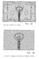
Figur 4a zeigt das auftretende magnetische Feld undFigur 4b die daraus folgende ohmsche Erwärmung. Beide Figuren stimmen sehr gut überein, d.h. Bereiche hoher magnetischer Feldstärke ergeben eine starke Erwärmung. -
Figur 5 zeigt das dazugehörige elektrische Feld. Das elektrische Feld ist am höchsten beim Übergang koaxiale Zuleitung Metallfläche und sehr klein in dem Bereich in dem die Kohlenstofffaserstruktur erwärmt wird, d.h. das magnetische und nicht das elektrische Feld heizt die Kohlenstofffaserstruktur und damit den gesamten Faser-Kunststoff-Verbundwerkstoff auf.
Claims (10)
- Verfahren zur Erwärmung eines Faser-Kunststoff-Verbundwerkstoffes (FKV) umfassend mindestens eine Lage (L) aus Kohlenstofffasern (F) in einer Kunststoffmatrix (K) wobei mittels Mikrowellenantenne (MA) ein magnetisches Feld (MF) induziert wird und die Feldrichtung des magnetischen Feldes (MF) in der Ebene der Lage (L) aus Kohlenstofffasern (F) verläuft.
- Verfahren nach Anspruch 1, dadurch gekennzeichnet, dass nur eine magnetische Feldrichtung während der Erwärmung des Faser-Kunststoff-Verbundwerkstoffes (FKV) vorliegt und diese in der Ebene der Lage (L) aus Kohlenstofffasern (F) verläuft.
- Verfahren nach Anspruch 1 oder 2, dadurch gekennzeichnet, dass der induzierte elektrische Strom (ES) orthogonal zur Ebene der Lage (L) aus Kohlenstofffasern (F) verläuft.
- Verfahren nach einem der vorhergehenden Ansprüche, dadurch gekennzeichnet, dass die Kunststoffmatrix (K) ein Duroplast und/oder ein Thermoplast ist/sind.
- Verfahren nach einem der vorhergehenden Ansprüche, dadurch gekennzeichnet, dass die Mikrowellenantenne (MA) eine Mikrowellenantenne nach einen der Ansprüche 7 bis 10 ist.
- Verfahren nach einem der vorhergehenden Ansprüche, dadurch gekennzeichnet, dass die Mikrowellenantenne (MA) 50 mm oder weniger oberhalb des Faser-Kunststoff-Verbundwerkstoffes (FKV) platziert wird.
- Mikrowellenantenne (MA) umfassend einen Schaft (S) und eine ebene Metallfläche (MF), wobei(a) der Schaft (S) einen Innenleiter (IL) und einen Außenleiter (AL) umfasst, wobei der Innenleiter (IL) und der Außenleiter (AL) durch ein Dielektrikum (D) getrennt sind und Innenleiter (IL) und Außenleiter (AL) koaxial zueinander verlaufen,(b) die Metallfläche (MF) die Form eines Kreissektors (KS) mit einem Winkel von 1° bis 180° und einem Radius von 1 cm bis 60,0 cm aufweist,(c) ein Ende des Innenleiters (IL) mit der Spitze der Metallfläche (MF) verbunden ist, die dem Winkel von 1° bis 180° zuzuordnen ist, wobei der Innenleiter (IL) mit der Ebene der Metallfläche (MF) einen Winkel zwischen 0° und 180° bildet.
- Mikrowellenantenne (MA) nach Anspruch 7, dadurch gekennzeichnet, dass der Schaft (S) 0,1 cm bis 25,0 cm vor dem Schaftende, welches mit der Metallfläche (MF) verbunden ist, nur den Innenleiter (IL) aufweist.
- Mikrowellenantenne (MA) nach Anspruch 7 oder 8, dadurch gekennzeichnet, dass die Metallfläche (MF) ein elektrisch leitfähiges Material, vorzugsweise Kupfer, Messing, Bronze, Aluminium, und/oder Edelstahl, umfasst.
- Mikrowellenantenne (MA) nach einem der vorhergehenden Ansprüche 7 bis 9, dadurch gekennzeichnet, dass(a) der Radius λ/1,8 bis λ/2,2 ist
und/oder(b) der Schaft (S) λ/2 bis λ/6 vor dem Schaftende, welches mit der Metallfläche (MF) verbunden ist, nur den Innenleiter (IL) aufweist, wobei "λ" die Wellenlänge der Mikrowelle mit einer Länge von 0,1 cm bis 100 cm ist.
Priority Applications (1)
| Application Number | Priority Date | Filing Date | Title |
|---|---|---|---|
| EP12181969.2A EP2546288B1 (de) | 2010-10-22 | 2011-10-13 | Mikrowellenantenne |
Applications Claiming Priority (1)
| Application Number | Priority Date | Filing Date | Title |
|---|---|---|---|
| DE102010042820A DE102010042820A1 (de) | 2010-10-22 | 2010-10-22 | Verfahren zur Erwärmung eines Faser-Kunststoff-Verbundwerkstoffes |
Related Child Applications (2)
| Application Number | Title | Priority Date | Filing Date |
|---|---|---|---|
| EP12181969.2A Division-Into EP2546288B1 (de) | 2010-10-22 | 2011-10-13 | Mikrowellenantenne |
| EP12181969.2A Division EP2546288B1 (de) | 2010-10-22 | 2011-10-13 | Mikrowellenantenne |
Publications (2)
| Publication Number | Publication Date |
|---|---|
| EP2444451A1 true EP2444451A1 (de) | 2012-04-25 |
| EP2444451B1 EP2444451B1 (de) | 2016-12-07 |
Family
ID=44905487
Family Applications (2)
| Application Number | Title | Priority Date | Filing Date |
|---|---|---|---|
| EP12181969.2A Not-in-force EP2546288B1 (de) | 2010-10-22 | 2011-10-13 | Mikrowellenantenne |
| EP11184980.8A Not-in-force EP2444451B1 (de) | 2010-10-22 | 2011-10-13 | Verfahren zur erwärmung eines faser-kunststoff-verbundwerkstoffes |
Family Applications Before (1)
| Application Number | Title | Priority Date | Filing Date |
|---|---|---|---|
| EP12181969.2A Not-in-force EP2546288B1 (de) | 2010-10-22 | 2011-10-13 | Mikrowellenantenne |
Country Status (3)
| Country | Link |
|---|---|
| US (1) | US9242394B2 (de) |
| EP (2) | EP2546288B1 (de) |
| DE (1) | DE102010042820A1 (de) |
Cited By (1)
| Publication number | Priority date | Publication date | Assignee | Title |
|---|---|---|---|---|
| DE202026101146U1 (de) | 2026-03-02 | 2026-04-23 | M & A - Dieterle GmbH Maschinen- und Apparatebau | Mikrowellen-Nahfeld-Applikator und System |
Families Citing this family (3)
| Publication number | Priority date | Publication date | Assignee | Title |
|---|---|---|---|---|
| US9394646B2 (en) * | 2012-08-10 | 2016-07-19 | Empire Technology Development Llc | Microwave dipolar heating of energetic polymers for carbon fiber-matrix separation |
| FR3033728B1 (fr) * | 2015-03-18 | 2017-12-08 | Institut De Recherche Et De Tech Jules Verne | Procede et dispositif de drapage et de soudage d’une bande textile comprenant un chauffage par micro-ondes |
| CN112909510B (zh) * | 2021-01-27 | 2022-11-25 | 宇联星程(浙江)科技有限公司 | 一种碳纤维镀银导电碳纤维复合材料天线 |
Citations (2)
| Publication number | Priority date | Publication date | Assignee | Title |
|---|---|---|---|---|
| US4819003A (en) * | 1984-03-24 | 1989-04-04 | Naohisa Goto | Flat circular unidirectional microwave antenna |
| US5798395A (en) * | 1994-03-31 | 1998-08-25 | Lambda Technologies Inc. | Adhesive bonding using variable frequency microwave energy |
Family Cites Families (23)
| Publication number | Priority date | Publication date | Assignee | Title |
|---|---|---|---|---|
| JPS5920992A (ja) | 1982-07-23 | 1984-02-02 | 松下電器産業株式会社 | 高周波加熱装置 |
| GB2127259B (en) * | 1982-08-31 | 1986-01-08 | Bosch Siemens Hausgeraete | High-frequency heating appliance |
| US4554608A (en) * | 1982-11-15 | 1985-11-19 | Block Roger R | Connector for electromagnetic impulse suppression |
| US4777336A (en) * | 1987-04-22 | 1988-10-11 | Michigan State University | Method for treating a material using radiofrequency waves |
| WO1989011311A1 (en) * | 1988-05-18 | 1989-11-30 | Kasevich Associates, Inc. | Microwave balloon angioplasty |
| FR2632890B1 (fr) * | 1988-06-16 | 1990-11-30 | Chausson Usines Sa | Procede et dispositif pour la mise en forme et la polymerisation de pieces en matiere plastique thermodurcissable |
| AU4209889A (en) * | 1988-09-09 | 1990-04-02 | Thomas H. Mcgaffigan | Temperature auto-regulating, self-heating recoverable articles |
| DE9200660U1 (de) | 1992-01-21 | 1992-03-12 | Bosch-Siemens Hausgeräte GmbH, 8000 München | Mikrowellenofen |
| US5576358A (en) * | 1995-02-03 | 1996-11-19 | Alliedsignal Inc. | Composition for use in friction materials and articles formed therefrom |
| JPH08213820A (ja) * | 1995-02-06 | 1996-08-20 | Nippon Sheet Glass Co Ltd | 自動車電話用ガラスアンテナ装置 |
| US6104934A (en) * | 1995-08-09 | 2000-08-15 | Spectral Solutions, Inc. | Cryoelectronic receiver front end |
| US6026762A (en) * | 1997-04-23 | 2000-02-22 | Applied Materials, Inc. | Apparatus for improved remote microwave plasma source for use with substrate processing systems |
| US6939477B2 (en) * | 1997-06-06 | 2005-09-06 | Ashland, Inc. | Temperature-controlled induction heating of polymeric materials |
| DE19937359C2 (de) | 1999-05-19 | 2001-06-07 | Fraunhofer Ges Forschung | Vorrichtung zum Erwärmen von Bauteilen aus mikrowellenabsorbierendem Kunststoff |
| US6259077B1 (en) * | 1999-07-12 | 2001-07-10 | Industrial Microwave Systems, Inc. | Method and apparatus for electromagnetic exposure of planar or other materials |
| CA2392078C (en) * | 1999-11-03 | 2005-02-22 | Nexicor Llc | Hand held induction tool |
| EP1428292A4 (de) * | 2001-09-07 | 2004-09-01 | Andrew Corp | Breitbandige basisstationsantenne und gruppenantenne |
| DE10157601B4 (de) * | 2001-11-26 | 2011-06-01 | Dieffenbacher Gmbh + Co. Kg | Vorrichtung zur Erwärmung von Pressgut bei der Herstellung von Werkstoffplatten |
| US7223087B2 (en) * | 2002-05-29 | 2007-05-29 | Razmik Akopyan | Microwave molding of polymers |
| JP4815832B2 (ja) * | 2005-03-24 | 2011-11-16 | ソニー株式会社 | アンテナおよびテレビ受信機 |
| US20070095823A1 (en) * | 2005-10-27 | 2007-05-03 | Sedlmayr Steven R | Microwave nucleon-electron-bonding spin alignment and alteration of materials |
| DE102006044487B4 (de) | 2006-09-21 | 2012-04-05 | Airbus Operations Gmbh | Verfahren zur Vor-Ort-Reparatur von Reparaturstellen an Bauteilen in Flugzeugen |
| JP2008166856A (ja) * | 2006-11-14 | 2008-07-17 | Ykc:Kk | アンテナ構造 |
-
2010
- 2010-10-22 DE DE102010042820A patent/DE102010042820A1/de not_active Withdrawn
-
2011
- 2011-10-13 EP EP12181969.2A patent/EP2546288B1/de not_active Not-in-force
- 2011-10-13 EP EP11184980.8A patent/EP2444451B1/de not_active Not-in-force
- 2011-10-20 US US13/277,804 patent/US9242394B2/en not_active Expired - Fee Related
Patent Citations (3)
| Publication number | Priority date | Publication date | Assignee | Title |
|---|---|---|---|---|
| US4819003A (en) * | 1984-03-24 | 1989-04-04 | Naohisa Goto | Flat circular unidirectional microwave antenna |
| US5798395A (en) * | 1994-03-31 | 1998-08-25 | Lambda Technologies Inc. | Adhesive bonding using variable frequency microwave energy |
| US5804801A (en) * | 1994-03-31 | 1998-09-08 | Lambda Technologies, Inc. | Adhesive bonding using variable frequency microwave energy |
Non-Patent Citations (1)
| Title |
|---|
| BRIAN B. BALZER ET AL: "Significant Effect of microwave Curing on Tensile Strength of carbon Fiber Composites", JOURNAL OF INDUSTRIAL TECHNOLOGY, VOLUME 24, NUMBER 3, JULY 2008 THROUGH SEPTEMBER 2008, 1 January 2008 (2008-01-01), pages 1 - 9, XP055018637, Retrieved from the Internet <URL:http://atmae.org/jit/Articles/balzer061608.pdf> [retrieved on 20120207] * |
Cited By (1)
| Publication number | Priority date | Publication date | Assignee | Title |
|---|---|---|---|---|
| DE202026101146U1 (de) | 2026-03-02 | 2026-04-23 | M & A - Dieterle GmbH Maschinen- und Apparatebau | Mikrowellen-Nahfeld-Applikator und System |
Also Published As
| Publication number | Publication date |
|---|---|
| DE102010042820A1 (de) | 2012-05-10 |
| EP2444451B1 (de) | 2016-12-07 |
| US9242394B2 (en) | 2016-01-26 |
| US20120160834A1 (en) | 2012-06-28 |
| EP2546288A1 (de) | 2013-01-16 |
| EP2546288B1 (de) | 2017-03-15 |
Similar Documents
| Publication | Publication Date | Title |
|---|---|---|
| EP3941713B1 (de) | Additiver herstellungsprozess einer form unter verwendung von mikrowellenstrahlung, mikrowellendruckvorrichtung und additive druckvorrichtung für 3d-druck eines einen faserverbundwerkstoff umfassenden filaments | |
| EP2303553B1 (de) | Herstellungsverfahren für bauteile aus faserverstärktem verbundwerkstoff mit mikrowellen | |
| DE69431394T2 (de) | Vorrichtung zur Einkopplung von Mikrowellenenergie während der Bearbeitung von bahnförmigen Material | |
| EP2444451B1 (de) | Verfahren zur erwärmung eines faser-kunststoff-verbundwerkstoffes | |
| EP2293924B1 (de) | Verfahren und formwerkzeug zur herstellung von bauteilen aus faserverstärktem verbundwerkstoff mit mikrowellen | |
| EP2612546B1 (de) | Emf-abgeschirmtes kunststoff-organoblech-hybrid-strukturbauteil | |
| EP2467246B1 (de) | Verfahren zum zusammenfügen von bauteilen | |
| DE102017111319A1 (de) | Einrichtung zur Erzeugung und Transmission von Hochfrequenzwellen (HF-Wellen) | |
| DE3300677A1 (de) | Applikator zum zu- und abfuehren von hochfrequenzenergie | |
| CN104845044B (zh) | 一种由纳米石墨粉体制备的涂覆式吸波材料及其制备方法 | |
| EP3737214A1 (de) | Ecr-ionenquelle und verfahren zum betreiben einer ecr-ionenquelle | |
| US20200280137A1 (en) | Method of controlling dielectric constant of composite material by micro pattern printing | |
| DE102005030745B4 (de) | HF-Spulen für Kernspintomographen | |
| DE112019003666T5 (de) | Harzelement und verfahren zur herstellung eines harzelements | |
| DE102011076262A1 (de) | Teilchenbeschleuniger | |
| EP3333857B1 (de) | Leitung und verfahren zur herstellung einer solchen | |
| WO2016055508A1 (de) | Drehübertrager mit schirmung aus gefüllten smc und / oder bmc materialien | |
| DE102014113338B4 (de) | Verfahren zum Temperieren und Temperiervorrichtung hierzu | |
| DE102019201957A1 (de) | Bauteil eines Kraftfahrzeugs, Radareinheit, Verfahren zur Herstellung eines Bauteils und Kraftfahrzeug | |
| Kayser et al. | An applicator for microwave assisted pultrusion of carbon fiber reinforced plastic | |
| EP2332215B1 (de) | Antennenvorrichtung für hochfrequente elektromagnetische wellen | |
| DE102020005695B4 (de) | Radarabsorbierendes Verbundbauteil | |
| DE102011083598A1 (de) | Leistungsmodul und Herstellungsverfahren | |
| DE102020125375A1 (de) | Verfahren zum Heizen von Objekten mit Mikrowellen | |
| DE102010053791A1 (de) | Mikrowellenquelle sowie Werkzeug umfassend eine Mikrowellenquelle |
Legal Events
| Date | Code | Title | Description |
|---|---|---|---|
| 17P | Request for examination filed |
Effective date: 20111013 |
|
| AK | Designated contracting states |
Kind code of ref document: A1 Designated state(s): AL AT BE BG CH CY CZ DE DK EE ES FI FR GB GR HR HU IE IS IT LI LT LU LV MC MK MT NL NO PL PT RO RS SE SI SK SM TR |
|
| AX | Request for extension of the european patent |
Extension state: BA ME |
|
| PUAI | Public reference made under article 153(3) epc to a published international application that has entered the european phase |
Free format text: ORIGINAL CODE: 0009012 |
|
| 17Q | First examination report despatched |
Effective date: 20160128 |
|
| RIC1 | Information provided on ipc code assigned before grant |
Ipc: B29C 35/02 20060101ALI20160414BHEP Ipc: B29C 70/06 20060101ALI20160414BHEP Ipc: B29K 105/08 20060101ALI20160414BHEP Ipc: B29C 35/08 20060101ALI20160414BHEP Ipc: H01Q 13/00 20060101ALI20160414BHEP Ipc: H01Q 9/40 20060101ALI20160414BHEP Ipc: H01Q 13/08 20060101ALI20160414BHEP Ipc: B29C 70/38 20060101ALI20160414BHEP Ipc: H01Q 1/36 20060101ALI20160414BHEP Ipc: C08J 3/28 20060101AFI20160414BHEP |
|
| GRAP | Despatch of communication of intention to grant a patent |
Free format text: ORIGINAL CODE: EPIDOSNIGR1 |
|
| INTG | Intention to grant announced |
Effective date: 20160601 |
|
| GRAS | Grant fee paid |
Free format text: ORIGINAL CODE: EPIDOSNIGR3 |
|
| GRAA | (expected) grant |
Free format text: ORIGINAL CODE: 0009210 |
|
| STAA | Information on the status of an ep patent application or granted ep patent |
Free format text: STATUS: THE PATENT HAS BEEN GRANTED |
|
| AK | Designated contracting states |
Kind code of ref document: B1 Designated state(s): AL AT BE BG CH CY CZ DE DK EE ES FI FR GB GR HR HU IE IS IT LI LT LU LV MC MK MT NL NO PL PT RO RS SE SI SK SM TR |
|
| REG | Reference to a national code |
Ref country code: GB Ref legal event code: FG4D Free format text: NOT ENGLISH |
|
| REG | Reference to a national code |
Ref country code: CH Ref legal event code: EP Ref country code: AT Ref legal event code: REF Ref document number: 851669 Country of ref document: AT Kind code of ref document: T Effective date: 20161215 |
|
| REG | Reference to a national code |
Ref country code: IE Ref legal event code: FG4D Free format text: LANGUAGE OF EP DOCUMENT: GERMAN |
|
| REG | Reference to a national code |
Ref country code: DE Ref legal event code: R096 Ref document number: 502011011276 Country of ref document: DE |
|
| PG25 | Lapsed in a contracting state [announced via postgrant information from national office to epo] |
Ref country code: LV Free format text: LAPSE BECAUSE OF FAILURE TO SUBMIT A TRANSLATION OF THE DESCRIPTION OR TO PAY THE FEE WITHIN THE PRESCRIBED TIME-LIMIT Effective date: 20161207 |
|
| REG | Reference to a national code |
Ref country code: LT Ref legal event code: MG4D |
|
| REG | Reference to a national code |
Ref country code: NL Ref legal event code: MP Effective date: 20161207 |
|
| PG25 | Lapsed in a contracting state [announced via postgrant information from national office to epo] |
Ref country code: GR Free format text: LAPSE BECAUSE OF FAILURE TO SUBMIT A TRANSLATION OF THE DESCRIPTION OR TO PAY THE FEE WITHIN THE PRESCRIBED TIME-LIMIT Effective date: 20170308 Ref country code: SE Free format text: LAPSE BECAUSE OF FAILURE TO SUBMIT A TRANSLATION OF THE DESCRIPTION OR TO PAY THE FEE WITHIN THE PRESCRIBED TIME-LIMIT Effective date: 20161207 Ref country code: NO Free format text: LAPSE BECAUSE OF FAILURE TO SUBMIT A TRANSLATION OF THE DESCRIPTION OR TO PAY THE FEE WITHIN THE PRESCRIBED TIME-LIMIT Effective date: 20170307 Ref country code: LT Free format text: LAPSE BECAUSE OF FAILURE TO SUBMIT A TRANSLATION OF THE DESCRIPTION OR TO PAY THE FEE WITHIN THE PRESCRIBED TIME-LIMIT Effective date: 20161207 |
|
| PG25 | Lapsed in a contracting state [announced via postgrant information from national office to epo] |
Ref country code: RS Free format text: LAPSE BECAUSE OF FAILURE TO SUBMIT A TRANSLATION OF THE DESCRIPTION OR TO PAY THE FEE WITHIN THE PRESCRIBED TIME-LIMIT Effective date: 20161207 Ref country code: ES Free format text: LAPSE BECAUSE OF FAILURE TO SUBMIT A TRANSLATION OF THE DESCRIPTION OR TO PAY THE FEE WITHIN THE PRESCRIBED TIME-LIMIT Effective date: 20161207 Ref country code: FI Free format text: LAPSE BECAUSE OF FAILURE TO SUBMIT A TRANSLATION OF THE DESCRIPTION OR TO PAY THE FEE WITHIN THE PRESCRIBED TIME-LIMIT Effective date: 20161207 Ref country code: HR Free format text: LAPSE BECAUSE OF FAILURE TO SUBMIT A TRANSLATION OF THE DESCRIPTION OR TO PAY THE FEE WITHIN THE PRESCRIBED TIME-LIMIT Effective date: 20161207 |
|
| PG25 | Lapsed in a contracting state [announced via postgrant information from national office to epo] |
Ref country code: NL Free format text: LAPSE BECAUSE OF FAILURE TO SUBMIT A TRANSLATION OF THE DESCRIPTION OR TO PAY THE FEE WITHIN THE PRESCRIBED TIME-LIMIT Effective date: 20161207 |
|
| PG25 | Lapsed in a contracting state [announced via postgrant information from national office to epo] |
Ref country code: RO Free format text: LAPSE BECAUSE OF FAILURE TO SUBMIT A TRANSLATION OF THE DESCRIPTION OR TO PAY THE FEE WITHIN THE PRESCRIBED TIME-LIMIT Effective date: 20161207 Ref country code: EE Free format text: LAPSE BECAUSE OF FAILURE TO SUBMIT A TRANSLATION OF THE DESCRIPTION OR TO PAY THE FEE WITHIN THE PRESCRIBED TIME-LIMIT Effective date: 20161207 Ref country code: CZ Free format text: LAPSE BECAUSE OF FAILURE TO SUBMIT A TRANSLATION OF THE DESCRIPTION OR TO PAY THE FEE WITHIN THE PRESCRIBED TIME-LIMIT Effective date: 20161207 Ref country code: IS Free format text: LAPSE BECAUSE OF FAILURE TO SUBMIT A TRANSLATION OF THE DESCRIPTION OR TO PAY THE FEE WITHIN THE PRESCRIBED TIME-LIMIT Effective date: 20170407 Ref country code: SK Free format text: LAPSE BECAUSE OF FAILURE TO SUBMIT A TRANSLATION OF THE DESCRIPTION OR TO PAY THE FEE WITHIN THE PRESCRIBED TIME-LIMIT Effective date: 20161207 |
|
| PG25 | Lapsed in a contracting state [announced via postgrant information from national office to epo] |
Ref country code: BG Free format text: LAPSE BECAUSE OF FAILURE TO SUBMIT A TRANSLATION OF THE DESCRIPTION OR TO PAY THE FEE WITHIN THE PRESCRIBED TIME-LIMIT Effective date: 20170307 Ref country code: PL Free format text: LAPSE BECAUSE OF FAILURE TO SUBMIT A TRANSLATION OF THE DESCRIPTION OR TO PAY THE FEE WITHIN THE PRESCRIBED TIME-LIMIT Effective date: 20161207 Ref country code: SM Free format text: LAPSE BECAUSE OF FAILURE TO SUBMIT A TRANSLATION OF THE DESCRIPTION OR TO PAY THE FEE WITHIN THE PRESCRIBED TIME-LIMIT Effective date: 20161207 Ref country code: IT Free format text: LAPSE BECAUSE OF FAILURE TO SUBMIT A TRANSLATION OF THE DESCRIPTION OR TO PAY THE FEE WITHIN THE PRESCRIBED TIME-LIMIT Effective date: 20161207 Ref country code: PT Free format text: LAPSE BECAUSE OF FAILURE TO SUBMIT A TRANSLATION OF THE DESCRIPTION OR TO PAY THE FEE WITHIN THE PRESCRIBED TIME-LIMIT Effective date: 20170407 |
|
| REG | Reference to a national code |
Ref country code: DE Ref legal event code: R097 Ref document number: 502011011276 Country of ref document: DE |
|
| PLBE | No opposition filed within time limit |
Free format text: ORIGINAL CODE: 0009261 |
|
| STAA | Information on the status of an ep patent application or granted ep patent |
Free format text: STATUS: NO OPPOSITION FILED WITHIN TIME LIMIT |
|
| 26N | No opposition filed |
Effective date: 20170908 |
|
| PG25 | Lapsed in a contracting state [announced via postgrant information from national office to epo] |
Ref country code: DK Free format text: LAPSE BECAUSE OF FAILURE TO SUBMIT A TRANSLATION OF THE DESCRIPTION OR TO PAY THE FEE WITHIN THE PRESCRIBED TIME-LIMIT Effective date: 20161207 Ref country code: SI Free format text: LAPSE BECAUSE OF FAILURE TO SUBMIT A TRANSLATION OF THE DESCRIPTION OR TO PAY THE FEE WITHIN THE PRESCRIBED TIME-LIMIT Effective date: 20161207 |
|
| PG25 | Lapsed in a contracting state [announced via postgrant information from national office to epo] |
Ref country code: MC Free format text: LAPSE BECAUSE OF FAILURE TO SUBMIT A TRANSLATION OF THE DESCRIPTION OR TO PAY THE FEE WITHIN THE PRESCRIBED TIME-LIMIT Effective date: 20161207 |
|
| REG | Reference to a national code |
Ref country code: CH Ref legal event code: PL |
|
| GBPC | Gb: european patent ceased through non-payment of renewal fee |
Effective date: 20171013 |
|
| REG | Reference to a national code |
Ref country code: IE Ref legal event code: MM4A |
|
| REG | Reference to a national code |
Ref country code: FR Ref legal event code: ST Effective date: 20180629 |
|
| PG25 | Lapsed in a contracting state [announced via postgrant information from national office to epo] |
Ref country code: CH Free format text: LAPSE BECAUSE OF NON-PAYMENT OF DUE FEES Effective date: 20171031 Ref country code: GB Free format text: LAPSE BECAUSE OF NON-PAYMENT OF DUE FEES Effective date: 20171013 Ref country code: LU Free format text: LAPSE BECAUSE OF NON-PAYMENT OF DUE FEES Effective date: 20171013 Ref country code: LI Free format text: LAPSE BECAUSE OF NON-PAYMENT OF DUE FEES Effective date: 20171031 |
|
| REG | Reference to a national code |
Ref country code: BE Ref legal event code: MM Effective date: 20171031 |
|
| PG25 | Lapsed in a contracting state [announced via postgrant information from national office to epo] |
Ref country code: FR Free format text: LAPSE BECAUSE OF NON-PAYMENT OF DUE FEES Effective date: 20171031 Ref country code: BE Free format text: LAPSE BECAUSE OF NON-PAYMENT OF DUE FEES Effective date: 20171031 |
|
| PG25 | Lapsed in a contracting state [announced via postgrant information from national office to epo] |
Ref country code: MT Free format text: LAPSE BECAUSE OF FAILURE TO SUBMIT A TRANSLATION OF THE DESCRIPTION OR TO PAY THE FEE WITHIN THE PRESCRIBED TIME-LIMIT Effective date: 20161207 |
|
| PG25 | Lapsed in a contracting state [announced via postgrant information from national office to epo] |
Ref country code: IE Free format text: LAPSE BECAUSE OF NON-PAYMENT OF DUE FEES Effective date: 20171013 |
|
| REG | Reference to a national code |
Ref country code: AT Ref legal event code: MM01 Ref document number: 851669 Country of ref document: AT Kind code of ref document: T Effective date: 20171013 |
|
| PG25 | Lapsed in a contracting state [announced via postgrant information from national office to epo] |
Ref country code: AT Free format text: LAPSE BECAUSE OF NON-PAYMENT OF DUE FEES Effective date: 20171013 |
|
| PG25 | Lapsed in a contracting state [announced via postgrant information from national office to epo] |
Ref country code: HU Free format text: LAPSE BECAUSE OF FAILURE TO SUBMIT A TRANSLATION OF THE DESCRIPTION OR TO PAY THE FEE WITHIN THE PRESCRIBED TIME-LIMIT; INVALID AB INITIO Effective date: 20111013 |
|
| PG25 | Lapsed in a contracting state [announced via postgrant information from national office to epo] |
Ref country code: CY Free format text: LAPSE BECAUSE OF NON-PAYMENT OF DUE FEES Effective date: 20161207 |
|
| PG25 | Lapsed in a contracting state [announced via postgrant information from national office to epo] |
Ref country code: MK Free format text: LAPSE BECAUSE OF FAILURE TO SUBMIT A TRANSLATION OF THE DESCRIPTION OR TO PAY THE FEE WITHIN THE PRESCRIBED TIME-LIMIT Effective date: 20161207 |
|
| PG25 | Lapsed in a contracting state [announced via postgrant information from national office to epo] |
Ref country code: TR Free format text: LAPSE BECAUSE OF FAILURE TO SUBMIT A TRANSLATION OF THE DESCRIPTION OR TO PAY THE FEE WITHIN THE PRESCRIBED TIME-LIMIT Effective date: 20161207 |
|
| PG25 | Lapsed in a contracting state [announced via postgrant information from national office to epo] |
Ref country code: AL Free format text: LAPSE BECAUSE OF FAILURE TO SUBMIT A TRANSLATION OF THE DESCRIPTION OR TO PAY THE FEE WITHIN THE PRESCRIBED TIME-LIMIT Effective date: 20161207 |
|
| PGFP | Annual fee paid to national office [announced via postgrant information from national office to epo] |
Ref country code: DE Payment date: 20211020 Year of fee payment: 11 |
|
| REG | Reference to a national code |
Ref country code: DE Ref legal event code: R119 Ref document number: 502011011276 Country of ref document: DE |
|
| P01 | Opt-out of the competence of the unified patent court (upc) registered |
Effective date: 20230524 |
|
| PG25 | Lapsed in a contracting state [announced via postgrant information from national office to epo] |
Ref country code: DE Free format text: LAPSE BECAUSE OF NON-PAYMENT OF DUE FEES Effective date: 20230503 |