EP2444349A2 - Traversor guide apparatus - Google Patents
Traversor guide apparatus Download PDFInfo
- Publication number
- EP2444349A2 EP2444349A2 EP11185591A EP11185591A EP2444349A2 EP 2444349 A2 EP2444349 A2 EP 2444349A2 EP 11185591 A EP11185591 A EP 11185591A EP 11185591 A EP11185591 A EP 11185591A EP 2444349 A2 EP2444349 A2 EP 2444349A2
- Authority
- EP
- European Patent Office
- Prior art keywords
- bobbin
- driving block
- rotation
- wire
- traversor
- Prior art date
- Legal status (The legal status is an assumption and is not a legal conclusion. Google has not performed a legal analysis and makes no representation as to the accuracy of the status listed.)
- Withdrawn
Links
- 230000002265 prevention Effects 0.000 claims abstract description 10
- 238000003780 insertion Methods 0.000 claims abstract description 8
- 230000037431 insertion Effects 0.000 claims abstract description 8
- 238000012546 transfer Methods 0.000 description 5
- 238000004804 winding Methods 0.000 description 5
- 238000010276 construction Methods 0.000 description 3
- 229910000831 Steel Inorganic materials 0.000 description 2
- 230000005540 biological transmission Effects 0.000 description 2
- 239000000463 material Substances 0.000 description 2
- 238000000034 method Methods 0.000 description 2
- 239000010959 steel Substances 0.000 description 2
- 238000010009 beating Methods 0.000 description 1
- 230000000694 effects Effects 0.000 description 1
- 230000007613 environmental effect Effects 0.000 description 1
- 238000005259 measurement Methods 0.000 description 1
- 238000012986 modification Methods 0.000 description 1
- 230000004048 modification Effects 0.000 description 1
- 230000035515 penetration Effects 0.000 description 1
- 239000011295 pitch Substances 0.000 description 1
- 238000004904 shortening Methods 0.000 description 1
- 238000009751 slip forming Methods 0.000 description 1
- 238000001363 water suppression through gradient tailored excitation Methods 0.000 description 1
Images




Classifications
-
- B—PERFORMING OPERATIONS; TRANSPORTING
- B65—CONVEYING; PACKING; STORING; HANDLING THIN OR FILAMENTARY MATERIAL
- B65H—HANDLING THIN OR FILAMENTARY MATERIAL, e.g. SHEETS, WEBS, CABLES
- B65H75/00—Storing webs, tapes, or filamentary material, e.g. on reels
- B65H75/02—Cores, formers, supports, or holders for coiled, wound, or folded material, e.g. reels, spindles, bobbins, cop tubes, cans, mandrels or chucks
- B65H75/18—Constructional details
- B65H75/26—Arrangements for preventing slipping of winding
- B65H75/265—Reels with grooves or grooved elements inhibiting aligned or orderly winding
-
- B—PERFORMING OPERATIONS; TRANSPORTING
- B65—CONVEYING; PACKING; STORING; HANDLING THIN OR FILAMENTARY MATERIAL
- B65H—HANDLING THIN OR FILAMENTARY MATERIAL, e.g. SHEETS, WEBS, CABLES
- B65H54/00—Winding, coiling, or depositing filamentary material
- B65H54/02—Winding and traversing material on to reels, bobbins, tubes, or like package cores or formers
- B65H54/28—Traversing devices; Package-shaping arrangements
- B65H54/2848—Arrangements for aligned winding
Definitions
- the present invention relates to a traversor guide apparatus, and in particular to a traversor guide apparatus which makes it possible to accurately measure a moved distance of an object by keeping a wire tightly wound on a bobbin even when a bobbin instantly rotates.
- the conventional traversors are disclosed in a Korean utility model publication number 1989-7806 entitled “traversor”, a Korean patent registration number 10-214358 entitled “a traversor guide apparatus with a continuously variable transmission function”, and a Korean utility model registration number 20-431019 entitled “traversor apparatus”.
- the Korean utility model publication number 1989-7806 entitled "traversor” is characterized in that an eccentric shaft in the interior of a body is made to cooperate with an angle adjusting lever and is closely attached to a semicircular tooth-shaped scale plate fixed at a front side, and a left and right movement bearing is installed at a lower side and is elastically disposed at an automatic operation member by using a coil spring, and a main drive bearing is inserted into a central shaft axially disposed at the automatic operation member and is supported at one side of the eccentric shaft, and a driven beating is axially supported at both sides, and a direction switch bracket is attached at its upper side for cooperation, so a steel material with a circular cross section can be reliably wound on a bobbin at regular intervals.
- the Korean patent registration number 10-214358 entitled "a traversor guide apparatus with a continuously variable transmission function” is characterized to comprise a slide shaft horizontally disposed at a rotatable body connected with a motor, a pair of slide bars which are horizontally disposed at the body and are positioned just above the slide shaft, a drive slider which can reciprocate straight along the slide shaft, a driven slider which is inserted movable into the slide bar in an engaged state to the drive slider, a support plate which is fixedly installed at the ends of the slide shaft and the slide bar, and a limit switch which is installed at a lower side of the drive slider and comes into contact with an operation plate which is installed at the body and the support plate, respectively, so the moving speed of the winding object guide can be optimum controlled to meet the general condition without changing the rotation speed of the slide shaft when the characteristic or the winding condition of the winding object is changed.
- the Korean utility model registration number 20-431019 entitled "traversor apparatus” is characterized to comprise a normal and reverse rotation driving force transfer apparatus engaged at an end portion of a table frame, a main shaft of which one end is engaged at the normal and reverse rotation driving force transfer apparatus, and the other end is engaged at a shaft rest disposed at the other end of the table frame, a slider which is engaged at the main shaft and moves left and right by means of the rotation of the main shaft, a guide shaft which is disposed in parallel with the main shaft for guiding the movement of the slider, a touch sensor which is engaged at two fixing shafts disposed at the lower side of the main shaft or limiting the moving range of the slider, a controller which is engaged at the table frame in such a way to control the operation of the normal and reverse rotation driving force transfer apparatus by receiving a signal from the touch sensor, and a driving motor which is disposed at a lower side of the table frame and transfers a driving force to the normal and reverse rotation driving force transfer apparatus via a belt, so that it is possible to precisely adjust the
- the wire connected to the measured object is wound or unwound from the bobbin 105 as the measured object moves; at this time a moving distance computation unit installed at one side of a rotary shaft 104 which functions like a rotation center of the bobbin 105 computes a moved distance of the measured object by computing the change in the length of the wire wound on the bobbin 105.
- the traversor is constructed in such a way that the rotary shaft 104 and the thread shaft 103 are connected by a timing belt 108, and a moving member 101 moving left and right in cooperation with the rotation of the thread shaft 103 is thread-engaged to the thread shaft 103, and a hole 02 is formed at the moving member 101 for feeding the wire connected with the measured object to the bobbin 105, so the moving member 101, namely, the hole 102 moves as the bobbin 105 rotates, thus adjusting the position where the wire having passed the hole 102 is to be wound.
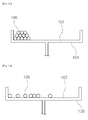
- the tensional fore of the wire wound on the bobbin 105 via the hole 102 of the moving member 101 is not easy to maintain due to diverse environmental changes, so the wire wound on the bobbin 105 is overlapped in double or triple tiers as shown in Figure 2A or is wound at different intervals as shown in Figure 2B , which results in a problem that the revolution of the bobbin 105 and the length of the wire wound on the bobbin 105 are not proportional to each other.
- the wires gets instantly wound on the bobbin or unwound from the same, which loosens the wire, thus twisting the wires.
- a traversor guide apparatus which comprises a cylindrical bobbin 10 which includes a plurality of spiral grooves 11, on which a wire 1 is wound, are formed in its outer surface at regular intervals in a longitudinal direction, and a rotation through hole 12 formed at a central portion of the interior of the same for receiving a shaft 2; a driving block 20 which includes an insertion hole 21, through which the wire 1 passes, and then is engaged to the spiral groove 11, and an engaging protrusion 22 formed at its inner surface and engaged to the spiral groove 11; and a cover 30 which covers an outer portion of the bobbin 10 and includes a guide slot 31 for guiding the driving block 20 so that the driving block 20 can move in a right angle direction to the rotation direction of the bobbin 10 during the rotation of the bobbin 10, wherein said guide slot 31 includes an inwardly protruded escape prevention part 32 contacting with an outer surface of the driving block 20 for thereby preventing an escape of the driving block 20 from happening.
- At least two engaging protrusions 22 are provided and thread-engaged with the spiral grooves 11, respectively, at two or more portions.
- the guide slot 31 further comprises an escape prevention part 32 which is inwardly protruded, thus preventing the escape of the driving block 20 from happening as the guide slot 31 comes into contact with the driving block 20.
- the traversor guide apparatus makes it possible to accurately measure a moved distance of an object by keeping a wire tightly wound on a bobbin even when a bobbin has an instant rotation.
- Figure 3 is a schematic view illustrating a state that a traversor guide apparatus is installed at a body according to a preferred embodiment of the present invention
- Figure 4 is a perspective view illustrating a traversor guide apparatus according to a preferred embodiment of the present invention
- Figure 5 is a disassembled perspective view illustrating a traversor guide apparatus according to a preferred embodiment of the present invention
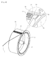
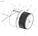
- Figures 6 and 7 are views illustrating a state that a wire having passed through an insertion of a driving block of a traversor guide apparatus is being wound on an outer surface of a bobbin according to a preferred embodiment of the present invention.
- the traversor guide apparatus comprises a bobbin 10, a driving block 20, a cover 30, a spiral groove 11, a rotation through hole 12, an insertion hole 12, an engaging protrusion 22, a guide slot 31 and an escape prevention part 32.
- the bobbin 10 will be first described.
- the bobbin 10 is made from a cylindrical member and has a spiral groove 11 on its outer surface.
- the spiral groove 11 is continuously formed in a spiral shape in its longitudinal direction.
- the engaging protrusion 22 of the driving block 20 is inserted into the spiral groove 11 and moves along an outer surface of the bobbin 10.
- the driving block 20 will be described.
- the driving block 20 is a member engaged to a spiral groove 11 formed on an outer surface of the bobbin 10.
- the engaging protrusion 22 formed on an inner surface of the driving block 20 is thread-engaged with the spiral groove 11.
- the driving block 20 moves along an outer surface of the bobbin 10 by means of the engagement between the spiral groove 11 and the engaging protrusion 22. At this time, the driving block 20 moves at the right angle direction with respect to the rotation direction of the bobbin 10 by means of the guide slot formed at the cover 30.
- At least two engaging protrusions 22 are provided.
- the driving block 20 can stably moved along the outer surface of the bobbin 10.
- the cover 30 will be described.
- the cover 30 serves to cover the outer side of the bobbin 10 and has a guide slot 31.
- the guide slot 31 becomes open in the direction in consistent with the longitudinal direction of the bobbin 10.
- the driving block 20 is guided in the longitudinal direction of the bobbin 10 by means of the guide slot 31.
- a driving block penetration part 33 sequentially formed with the guide slot 31 is formed at one end of the cover 30 so that the driving block 20 can penetrate into the guide slot 31 when the cover 30 and the bobbin 10 engaged with each other.
- the escape prevention part 32 is formed at the guide slot 31 for preventing the escape of the driving block 20 from happening.
- the escape prevention part 32 is inwardly protruded from the upper side of the guide slot 31.
- the inner lower surface of the inwardly protruded escape prevention part 32 contacts with the outer surface of the driving block 20, thus preventing the escape of the driving block 20 from happening.
- the cover 30 covers the outer surface of the bobbin 10 in such a way to reliably fix the wire 1 at the spiral groove 11.
- the driving block 20 is fixed by the cover 30; however a hook (not shown) to be elastically engaged with the spiral groove 11 might be provided at the driving block 20.
- the escape prevention part 32 is protruded to an extent that the position of the driving block 20 can be recognized by a photo sensor from the outside while preventing an escape of the driving block 20 from happening.
Landscapes
- Guides For Winding Or Rewinding, Or Guides For Filamentary Materials (AREA)
Abstract
A traversor guide apparatus is disclosed, which comprises a cylindrical bobbin 10 which includes a plurality of spiral grooves 11, on which a wire 1 is wound, are formed in its outer surface at regular intervals in a longitudinal direction, and a rotation through hole 12 formed at a central portion of the interior of the same for receiving a shaft 2; a driving block 20 which includes an insertion hole 21, through which the wire 1 passes, and then is engaged to the spiral groove 11, and an engaging protrusion 22 formed at its inner surface and engaged to the spiral groove 11; and a cover 30 which covers an outer portion of the bobbin 10 and includes a guide slot 31 for guiding the driving block 20 so that the driving block 20 can move in a right angle direction to the rotation direction of the bobbin 10 during the rotation of the bobbin 10, wherein the guide slot 31 includes an inwardly protruded escape prevention part 32 contacting with an outer surface of the driving block 20 for thereby preventing an escape of the driving block 20 from happening. The present invention makes it possible to accurately measure a moved distance of an object by keeping a wire tightly wound on a bobbin even when a bobbin has an instant rotation.
Description
- The present invention relates to a traversor guide apparatus, and in particular to a traversor guide apparatus which makes it possible to accurately measure a moved distance of an object by keeping a wire tightly wound on a bobbin even when a bobbin instantly rotates.
- The conventional traversors are disclosed in a Korean utility model publication number
1989-7806 10-214358 20-431019 - The Korean utility model publication number
1989-7806 - Next, the Korean patent registration number
10-214358 - Next, the Korean utility model registration number
20-431019 - The above-described conventional arts are directed to a winding per se; however the traversor of
Figure 1 is used a measuring sensor which makes it possible to measure the moved distance of an object, to be measured, like a cylinder or other firefighting hose, the cylinder designed to open the water gate by using a change in the length of the wire wound on the bobbin. - The wire connected to the measured object is wound or unwound from the
bobbin 105 as the measured object moves; at this time a moving distance computation unit installed at one side of arotary shaft 104 which functions like a rotation center of thebobbin 105 computes a moved distance of the measured object by computing the change in the length of the wire wound on thebobbin 105. - The traversor is constructed in such a way that the
rotary shaft 104 and thethread shaft 103 are connected by atiming belt 108, and a movingmember 101 moving left and right in cooperation with the rotation of thethread shaft 103 is thread-engaged to thethread shaft 103, and a hole 02 is formed at the movingmember 101 for feeding the wire connected with the measured object to thebobbin 105, so the movingmember 101, namely, thehole 102 moves as thebobbin 105 rotates, thus adjusting the position where the wire having passed thehole 102 is to be wound. - In the above arts, the tensional fore of the wire wound on the
bobbin 105 via thehole 102 of the movingmember 101 is not easy to maintain due to diverse environmental changes, so the wire wound on thebobbin 105 is overlapped in double or triple tiers as shown inFigure 2A or is wound at different intervals as shown inFigure 2B , which results in a problem that the revolution of thebobbin 105 and the length of the wire wound on thebobbin 105 are not proportional to each other. - In other words, what the revolution of the
bobbin 105 and the length of the wire wound on thebobbin 105 are not proportional to each other comes since the measurement of the moved distance of the measure object is not accurate. When the wire as shown inFigure 2A is overlapped once or more, friction occurs between the wires, thus damaging the wire, which leads to shortening the service life of wires. - When the position of the measured object is instantly moved, the wires gets instantly wound on the bobbin or unwound from the same, which loosens the wire, thus twisting the wires.
- Accordingly, it is an object of the present invention to provide a traversor guide apparatus which overcomes the above problems and makes it possible to accurately measure a moved distance of an object by keeping a wire tightly wound on a bobbin even when a bobbin instantly rotates.
- To achieve the above object, there is provided a traversor guide apparatus which comprises a
cylindrical bobbin 10 which includes a plurality ofspiral grooves 11, on which awire 1 is wound, are formed in its outer surface at regular intervals in a longitudinal direction, and a rotation throughhole 12 formed at a central portion of the interior of the same for receiving ashaft 2; adriving block 20 which includes aninsertion hole 21, through which thewire 1 passes, and then is engaged to thespiral groove 11, and an engaging protrusion 22 formed at its inner surface and engaged to thespiral groove 11; and acover 30 which covers an outer portion of thebobbin 10 and includes aguide slot 31 for guiding thedriving block 20 so that thedriving block 20 can move in a right angle direction to the rotation direction of thebobbin 10 during the rotation of thebobbin 10, wherein saidguide slot 31 includes an inwardly protrudedescape prevention part 32 contacting with an outer surface of thedriving block 20 for thereby preventing an escape of thedriving block 20 from happening. - In addition, at least two engaging protrusions 22 are provided and thread-engaged with the
spiral grooves 11, respectively, at two or more portions. - In addition, the
guide slot 31 further comprises anescape prevention part 32 which is inwardly protruded, thus preventing the escape of thedriving block 20 from happening as theguide slot 31 comes into contact with thedriving block 20. - The traversor guide apparatus according to the present invention makes it possible to accurately measure a moved distance of an object by keeping a wire tightly wound on a bobbin even when a bobbin has an instant rotation.
- The present invention will become better understood with reference to the accompanying drawings which are given only by way of illustration and thus are not limitative of the present invention, wherein;
-
Figure 1 is a perspective view illustrating a conventional traversor guide apparatus; -
Figures 2A and 2B are schematic side views illustrating a state that a wire is wound on a bobbin in a non-uniform shape by means of the traversor guide apparatus ofFigure 1 ; -
Figure 3 is a schematic view illustrating a state that a traversor guide apparatus is installed at a body according to a preferred embodiment of the present invention; -
Figure 4 is a perspective view illustrating a traversor guide apparatus according to a preferred embodiment of the present invention; -
Figure 5 is a disassembled perspective view illustrating a traversor guide apparatus according to a preferred embodiment of the present invention; and -
Figures 6 and7 are views illustrating a state that a wire having passed through an insertion of a driving block of a traversor guide apparatus is being wound on an outer surface of a bobbin according to a preferred embodiment of the present invention. - The preferred embodiments of the present invention will be described with reference to the accompanying drawings. The same references of the figures represent the same elements. In the descriptions of the present invention, the detailed descriptions of the related known functions or construction will be omitted so as to clarify the subject matters of the present invention.
-
Figure 3 is a schematic view illustrating a state that a traversor guide apparatus is installed at a body according to a preferred embodiment of the present invention,Figure 4 is a perspective view illustrating a traversor guide apparatus according to a preferred embodiment of the present invention,Figure 5 is a disassembled perspective view illustrating a traversor guide apparatus according to a preferred embodiment of the present invention; andFigures 6 and7 are views illustrating a state that a wire having passed through an insertion of a driving block of a traversor guide apparatus is being wound on an outer surface of a bobbin according to a preferred embodiment of the present invention. - The traversor guide apparatus according to a preferred embodiment of the present invention comprises a
bobbin 10, adriving block 20, acover 30, aspiral groove 11, a rotation throughhole 12, aninsertion hole 12, an engaging protrusion 22, aguide slot 31 and anescape prevention part 32. - The
bobbin 10 will be first described. - As shown in
Figures 3 and4 , thebobbin 10 is made from a cylindrical member and has aspiral groove 11 on its outer surface. Thespiral groove 11 is continuously formed in a spiral shape in its longitudinal direction. The engaging protrusion 22 of thedriving block 20 is inserted into thespiral groove 11 and moves along an outer surface of thebobbin 10. - As shown in
Figures 3 and4 , at the inner center of thebobbin 10 is formed a rotation throughhole 12, and a shaft is inserted into the rotation throughhole 12. The engaging construction and method of theshaft 2 and the rotation throughhole 12 might be implemented like the disclosure of the Korean patent registration number10-0927441 - The
driving block 20 will be described. - As shown in
Figures 3 and4 , thedriving block 20 is a member engaged to aspiral groove 11 formed on an outer surface of thebobbin 10. When the rivingblock 20 comes into contact with thebobbin 10, the engaging protrusion 22 formed on an inner surface of thedriving block 20 is thread-engaged with thespiral groove 11. - When the
bobbin 10 rotates about theshaft 2 inserted in the rotation throughhole 12 thedriving block 20 moves along an outer surface of thebobbin 10 by means of the engagement between thespiral groove 11 and the engaging protrusion 22. At this time, thedriving block 20 moves at the right angle direction with respect to the rotation direction of thebobbin 10 by means of the guide slot formed at thecover 30. - As shown in
Figure 7 , at least two engaging protrusions 22 are provided. When more than two engaging protrusions22 are provided, since the contact area between thedriving block 20 and thebobbin 10 increases, thedriving block 20 can stably moved along the outer surface of thebobbin 10. - The
cover 30 will be described. - The
cover 30 serves to cover the outer side of thebobbin 10 and has aguide slot 31. - The
guide slot 31 becomes open in the direction in consistent with the longitudinal direction of thebobbin 10. Thedriving block 20 is guided in the longitudinal direction of thebobbin 10 by means of theguide slot 31. - As shown in
Figures 5 and6 , it is preferred that a drivingblock penetration part 33 sequentially formed with theguide slot 31 is formed at one end of thecover 30 so that thedriving block 20 can penetrate into theguide slot 31 when thecover 30 and thebobbin 10 engaged with each other. - It is preferred that the
escape prevention part 32 is formed at theguide slot 31 for preventing the escape of thedriving block 20 from happening. Theescape prevention part 32 is inwardly protruded from the upper side of theguide slot 31. - The inner lower surface of the inwardly protruded
escape prevention part 32 contacts with the outer surface of thedriving block 20, thus preventing the escape of thedriving block 20 from happening. - The
cover 30 covers the outer surface of thebobbin 10 in such a way to reliably fix thewire 1 at thespiral groove 11. - In another example of the present invention, the
driving block 20 is fixed by thecover 30; however a hook (not shown) to be elastically engaged with thespiral groove 11 might be provided at thedriving block 20. - It is preferred that the
escape prevention part 32 is protruded to an extent that the position of thedriving block 20 can be recognized by a photo sensor from the outside while preventing an escape of thedriving block 20 from happening. - As shown in
Figures 6 and7 , there is shown an example that the wire having passed through theinsertion hole 21 of thedriving block 20 is wound on an outer surface of thebobbin 10, so thewire 1 can be more reliably fixed by the inner surface of thecover 30. - As the present invention may be embodied in several forms without departing from the spirit or essential characteristics thereof, it should also be understood that the above-described examples are not limited by any of the details of the foregoing description, unless otherwise specified, but rather should be construed broadly within its spirit and scope as defined in the appended claims, and therefore all changes and modifications that fall within the meets and bounds of the claims, or equivalences of such meets and bounds are therefore intended to be embraced by the appended claims.
-
10: bobbin 11: spiral groove 12 rotation through hole 20: driving block 21: insertion hole 22: engaging protrusion 30: cover 31: guide slot 32: escape prevention part
Claims (2)
- A traversor guide apparatus, comprising:a cylindrical bobbin 10 which includes a plurality of spiral grooves 11, on which a wire 1 is wound, are formed in its outer surface at regular intervals in a longitudinal direction, and a rotation through hole 12 formed at a central portion of the interior of the same for receiving a shaft 2;a driving block 20 which includes an insertion hole 21, through which the wire 1 passes, and then is engaged to the spiral groove 11, and an engaging protrusion 22 formed at its inner surface and engaged to the spiral groove 11; anda cover 30 which covers an outer portion of the bobbin 10 and includes a guide slot 31 for guiding the driving block 20 so that the driving block 20 can move in a right angle direction to the rotation direction of the bobbin 10 during the rotation of the bobbin 10, wherein said guide slot 31 includes an inwardly protruded escape prevention part 32 contacting with an outer surface of the driving block 20 for thereby preventing an escape of the driving block 20 from happening.
- The apparatus of claim 1, wherein at least two engaging protrusions 22 are provided and thread-engaged with the spiral grooves 11, respectively, at two or more portions.
Applications Claiming Priority (1)
| Application Number | Priority Date | Filing Date | Title |
|---|---|---|---|
| KR1020100101720A KR101059076B1 (en) | 2010-10-19 | 2010-10-19 | Trevasha guide device |
Publications (1)
| Publication Number | Publication Date |
|---|---|
| EP2444349A2 true EP2444349A2 (en) | 2012-04-25 |
Family
ID=44862580
Family Applications (1)
| Application Number | Title | Priority Date | Filing Date |
|---|---|---|---|
| EP11185591A Withdrawn EP2444349A2 (en) | 2010-10-19 | 2011-10-18 | Traversor guide apparatus |
Country Status (3)
| Country | Link |
|---|---|
| US (1) | US20120091247A1 (en) |
| EP (1) | EP2444349A2 (en) |
| KR (1) | KR101059076B1 (en) |
Cited By (1)
| Publication number | Priority date | Publication date | Assignee | Title |
|---|---|---|---|---|
| CN109850680A (en) * | 2018-12-07 | 2019-06-07 | 合肥森隆环保科技有限公司 | A kind of quick bobbin winder device of new-energy automobile |
Families Citing this family (3)
| Publication number | Priority date | Publication date | Assignee | Title |
|---|---|---|---|---|
| KR101166687B1 (en) | 2011-11-24 | 2012-07-19 | 한국기계연구원 | Method of wire winding arrangement for multi wire saw |
| KR102207350B1 (en) * | 2019-02-01 | 2021-01-25 | 주식회사 오모로봇 | A wrap apparatus |
| KR102611251B1 (en) * | 2021-06-24 | 2023-12-07 | 석병노 | Winding device for hose manufacturing |
Citations (4)
| Publication number | Priority date | Publication date | Assignee | Title |
|---|---|---|---|---|
| KR890007806Y1 (en) | 1986-12-29 | 1989-11-08 | 김명영 | Trevasha |
| KR100214358B1 (en) | 1996-12-13 | 1999-08-02 | 손제익 | Traverse guide |
| KR200431019Y1 (en) | 2006-07-12 | 2006-11-13 | 손남옥 | Traverse device |
| KR100927441B1 (en) | 2009-05-29 | 2009-11-19 | 선비기술 주식회사 | Trevasha guide device |
Family Cites Families (10)
| Publication number | Priority date | Publication date | Assignee | Title |
|---|---|---|---|---|
| US3315914A (en) * | 1965-07-21 | 1967-04-25 | Donald L Turner | Ski rope reel and tow mechanism |
| US3801032A (en) * | 1972-05-15 | 1974-04-02 | Owens Corning Fiberglass Corp | Apparatus for packaging strand |
| US4025003A (en) * | 1975-02-24 | 1977-05-24 | Kabushiki Kaisha Toyoda Jidoshokki Seisakusho | Device for simultaneously traversing thread guides of a winding apparatus for taking up a plurality of threads |
| CH615354A5 (en) * | 1977-02-04 | 1980-01-31 | Rieter Ag Maschf | |
| DE2843208A1 (en) * | 1978-10-04 | 1980-04-17 | Barmag Barmer Maschf | FINDING REEL DEVICE |
| DE19536761A1 (en) * | 1995-10-02 | 1997-04-03 | Schlafhorst & Co W | Reversing drive for thread guides for cross spool winder |
| KR200219390Y1 (en) | 2000-09-26 | 2001-04-02 | 대원기계공업주식회사 | A traverse running gear in twisting machine |
| JP2005200114A (en) | 2004-01-13 | 2005-07-28 | Sumitomo Electric Ind Ltd | Wire body winding method and winding device |
| JP2007254124A (en) | 2006-03-24 | 2007-10-04 | Kyocera Corp | Traverse guide |
| PL2151411T3 (en) * | 2008-08-07 | 2012-03-30 | Harken Italy Spa | Cable collecting winch |
-
2010
- 2010-10-19 KR KR1020100101720A patent/KR101059076B1/en not_active Expired - Fee Related
-
2011
- 2011-09-15 US US13/233,494 patent/US20120091247A1/en not_active Abandoned
- 2011-10-18 EP EP11185591A patent/EP2444349A2/en not_active Withdrawn
Patent Citations (4)
| Publication number | Priority date | Publication date | Assignee | Title |
|---|---|---|---|---|
| KR890007806Y1 (en) | 1986-12-29 | 1989-11-08 | 김명영 | Trevasha |
| KR100214358B1 (en) | 1996-12-13 | 1999-08-02 | 손제익 | Traverse guide |
| KR200431019Y1 (en) | 2006-07-12 | 2006-11-13 | 손남옥 | Traverse device |
| KR100927441B1 (en) | 2009-05-29 | 2009-11-19 | 선비기술 주식회사 | Trevasha guide device |
Cited By (1)
| Publication number | Priority date | Publication date | Assignee | Title |
|---|---|---|---|---|
| CN109850680A (en) * | 2018-12-07 | 2019-06-07 | 合肥森隆环保科技有限公司 | A kind of quick bobbin winder device of new-energy automobile |
Also Published As
| Publication number | Publication date |
|---|---|
| US20120091247A1 (en) | 2012-04-19 |
| KR101059076B1 (en) | 2011-08-24 |
Similar Documents
| Publication | Publication Date | Title |
|---|---|---|
| US20120091247A1 (en) | Traversor guide apparatus | |
| US20080292058A1 (en) | Device for Limiting Field on Which Radiation is Irradiated | |
| EP3444085B1 (en) | Automatic sizing cutting device | |
| KR101745514B1 (en) | Wire winch for stage facility | |
| US4918958A (en) | Device for bending conical wires | |
| EP2829647A1 (en) | Yarn feeder provided with a weft-winding drum and with a feedback-controlled, weft-braking device | |
| KR20130135228A (en) | Apparatus for correcting meandering of continuous sheet for absorbent product | |
| KR101402237B1 (en) | Winding error compensation apparatus of wire saw and Wire saw with the same | |
| CN103863889B (en) | The devices for taking-up of wire rod and the method for coiling of wire rod | |
| KR20190063036A (en) | Apparatus for measuring quality of water | |
| CN108883453A (en) | Manufacturing equipment with a conveyor mechanism with permanent magnets for processing wire wound into coils | |
| JPH0367939B2 (en) | ||
| KR101964138B1 (en) | Optical cable spooler by one-way clutch | |
| KR100927441B1 (en) | Trevasha guide device | |
| US20190047039A1 (en) | Machining system for machining round material, comprising a feeder assembly having permanent magnets | |
| US6018975A (en) | Multipass wiredrawing machine with wire tension control device | |
| EP4431427A1 (en) | Positive yarn feeder, particularly for yarn feeding apparatuses for warping machines | |
| JP2002213940A (en) | Linear body size measuring device | |
| US6094945A (en) | Device for feeding an elastically extendable yarn to hosiery knitting machines | |
| CN116675086B (en) | Elevator safety system and elevator safety control method | |
| CN216272511U (en) | Wire winding device | |
| EP4332036A1 (en) | Yarn length measurement device and knitting yarn buffer device | |
| KR20010064198A (en) | Device for amending top grip of hot coil | |
| KR100777323B1 (en) | Blanking Machine for Coil Steel Sheet | |
| JPH0559026B2 (en) |
Legal Events
| Date | Code | Title | Description |
|---|---|---|---|
| AK | Designated contracting states |
Kind code of ref document: A2 Designated state(s): AL AT BE BG CH CY CZ DE DK EE ES FI FR GB GR HR HU IE IS IT LI LT LU LV MC MK MT NL NO PL PT RO RS SE SI SK SM TR |
|
| AX | Request for extension of the european patent |
Extension state: BA ME |
|
| PUAI | Public reference made under article 153(3) epc to a published international application that has entered the european phase |
Free format text: ORIGINAL CODE: 0009012 |
|
| STAA | Information on the status of an ep patent application or granted ep patent |
Free format text: STATUS: THE APPLICATION IS DEEMED TO BE WITHDRAWN |
|
| 18D | Application deemed to be withdrawn |
Effective date: 20150501 |