EP2444288A1 - Industrial vehicle control device - Google Patents
Industrial vehicle control device Download PDFInfo
- Publication number
- EP2444288A1 EP2444288A1 EP10789584A EP10789584A EP2444288A1 EP 2444288 A1 EP2444288 A1 EP 2444288A1 EP 10789584 A EP10789584 A EP 10789584A EP 10789584 A EP10789584 A EP 10789584A EP 2444288 A1 EP2444288 A1 EP 2444288A1
- Authority
- EP
- European Patent Office
- Prior art keywords
- speed ratio
- torque converter
- decision
- gear
- speed
- Prior art date
- Legal status (The legal status is an assumption and is not a legal conclusion. Google has not performed a legal analysis and makes no representation as to the accuracy of the status listed.)
- Granted
Links
- 239000000446 fuel Substances 0.000 claims abstract description 41
- 230000002542 deteriorative effect Effects 0.000 claims abstract description 24
- 238000001514 detection method Methods 0.000 claims abstract description 12
- 230000005540 biological transmission Effects 0.000 claims description 18
- 230000002459 sustained effect Effects 0.000 claims description 10
- 230000007423 decrease Effects 0.000 claims description 7
- 238000010586 diagram Methods 0.000 description 9
- XDDAORKBJWWYJS-UHFFFAOYSA-N glyphosate Chemical compound OC(=O)CNCP(O)(O)=O XDDAORKBJWWYJS-UHFFFAOYSA-N 0.000 description 3
- 238000000034 method Methods 0.000 description 3
- 239000012530 fluid Substances 0.000 description 2
- 230000001133 acceleration Effects 0.000 description 1
- 238000006243 chemical reaction Methods 0.000 description 1
- 230000001010 compromised effect Effects 0.000 description 1
- 239000000498 cooling water Substances 0.000 description 1
- 230000000694 effects Effects 0.000 description 1
- 238000013021 overheating Methods 0.000 description 1
- 230000002093 peripheral effect Effects 0.000 description 1
- 230000035939 shock Effects 0.000 description 1
Images


Classifications
-
- B—PERFORMING OPERATIONS; TRANSPORTING
- B60—VEHICLES IN GENERAL
- B60W—CONJOINT CONTROL OF VEHICLE SUB-UNITS OF DIFFERENT TYPE OR DIFFERENT FUNCTION; CONTROL SYSTEMS SPECIALLY ADAPTED FOR HYBRID VEHICLES; ROAD VEHICLE DRIVE CONTROL SYSTEMS FOR PURPOSES NOT RELATED TO THE CONTROL OF A PARTICULAR SUB-UNIT
- B60W50/00—Details of control systems for road vehicle drive control not related to the control of a particular sub-unit, e.g. process diagnostic or vehicle driver interfaces
- B60W50/08—Interaction between the driver and the control system
- B60W50/14—Means for informing the driver, warning the driver or prompting a driver intervention
-
- B60K35/28—
-
- B—PERFORMING OPERATIONS; TRANSPORTING
- B60—VEHICLES IN GENERAL
- B60W—CONJOINT CONTROL OF VEHICLE SUB-UNITS OF DIFFERENT TYPE OR DIFFERENT FUNCTION; CONTROL SYSTEMS SPECIALLY ADAPTED FOR HYBRID VEHICLES; ROAD VEHICLE DRIVE CONTROL SYSTEMS FOR PURPOSES NOT RELATED TO THE CONTROL OF A PARTICULAR SUB-UNIT
- B60W10/00—Conjoint control of vehicle sub-units of different type or different function
- B60W10/04—Conjoint control of vehicle sub-units of different type or different function including control of propulsion units
- B60W10/06—Conjoint control of vehicle sub-units of different type or different function including control of propulsion units including control of combustion engines
-
- B—PERFORMING OPERATIONS; TRANSPORTING
- B60—VEHICLES IN GENERAL
- B60W—CONJOINT CONTROL OF VEHICLE SUB-UNITS OF DIFFERENT TYPE OR DIFFERENT FUNCTION; CONTROL SYSTEMS SPECIALLY ADAPTED FOR HYBRID VEHICLES; ROAD VEHICLE DRIVE CONTROL SYSTEMS FOR PURPOSES NOT RELATED TO THE CONTROL OF A PARTICULAR SUB-UNIT
- B60W10/00—Conjoint control of vehicle sub-units of different type or different function
- B60W10/10—Conjoint control of vehicle sub-units of different type or different function including control of change-speed gearings
-
- B—PERFORMING OPERATIONS; TRANSPORTING
- B60—VEHICLES IN GENERAL
- B60W—CONJOINT CONTROL OF VEHICLE SUB-UNITS OF DIFFERENT TYPE OR DIFFERENT FUNCTION; CONTROL SYSTEMS SPECIALLY ADAPTED FOR HYBRID VEHICLES; ROAD VEHICLE DRIVE CONTROL SYSTEMS FOR PURPOSES NOT RELATED TO THE CONTROL OF A PARTICULAR SUB-UNIT
- B60W30/00—Purposes of road vehicle drive control systems not related to the control of a particular sub-unit, e.g. of systems using conjoint control of vehicle sub-units, or advanced driver assistance systems for ensuring comfort, stability and safety or drive control systems for propelling or retarding the vehicle
- B60W30/18—Propelling the vehicle
- B60W30/188—Controlling power parameters of the driveline, e.g. determining the required power
- B60W30/1882—Controlling power parameters of the driveline, e.g. determining the required power characterised by the working point of the engine, e.g. by using engine output chart
-
- B—PERFORMING OPERATIONS; TRANSPORTING
- B60—VEHICLES IN GENERAL
- B60W—CONJOINT CONTROL OF VEHICLE SUB-UNITS OF DIFFERENT TYPE OR DIFFERENT FUNCTION; CONTROL SYSTEMS SPECIALLY ADAPTED FOR HYBRID VEHICLES; ROAD VEHICLE DRIVE CONTROL SYSTEMS FOR PURPOSES NOT RELATED TO THE CONTROL OF A PARTICULAR SUB-UNIT
- B60W40/00—Estimation or calculation of non-directly measurable driving parameters for road vehicle drive control systems not related to the control of a particular sub unit, e.g. by using mathematical models
- B60W40/10—Estimation or calculation of non-directly measurable driving parameters for road vehicle drive control systems not related to the control of a particular sub unit, e.g. by using mathematical models related to vehicle motion
- B60W40/105—Speed
-
- B60K2360/174—
-
- B—PERFORMING OPERATIONS; TRANSPORTING
- B60—VEHICLES IN GENERAL
- B60W—CONJOINT CONTROL OF VEHICLE SUB-UNITS OF DIFFERENT TYPE OR DIFFERENT FUNCTION; CONTROL SYSTEMS SPECIALLY ADAPTED FOR HYBRID VEHICLES; ROAD VEHICLE DRIVE CONTROL SYSTEMS FOR PURPOSES NOT RELATED TO THE CONTROL OF A PARTICULAR SUB-UNIT
- B60W2300/00—Indexing codes relating to the type of vehicle
- B60W2300/17—Construction vehicles, e.g. graders, excavators
-
- B—PERFORMING OPERATIONS; TRANSPORTING
- B60—VEHICLES IN GENERAL
- B60W—CONJOINT CONTROL OF VEHICLE SUB-UNITS OF DIFFERENT TYPE OR DIFFERENT FUNCTION; CONTROL SYSTEMS SPECIALLY ADAPTED FOR HYBRID VEHICLES; ROAD VEHICLE DRIVE CONTROL SYSTEMS FOR PURPOSES NOT RELATED TO THE CONTROL OF A PARTICULAR SUB-UNIT
- B60W2510/00—Input parameters relating to a particular sub-units
- B60W2510/02—Clutches
- B60W2510/0241—Clutch slip, i.e. difference between input and output speeds
-
- B—PERFORMING OPERATIONS; TRANSPORTING
- B60—VEHICLES IN GENERAL
- B60W—CONJOINT CONTROL OF VEHICLE SUB-UNITS OF DIFFERENT TYPE OR DIFFERENT FUNCTION; CONTROL SYSTEMS SPECIALLY ADAPTED FOR HYBRID VEHICLES; ROAD VEHICLE DRIVE CONTROL SYSTEMS FOR PURPOSES NOT RELATED TO THE CONTROL OF A PARTICULAR SUB-UNIT
- B60W2510/00—Input parameters relating to a particular sub-units
- B60W2510/06—Combustion engines, Gas turbines
- B60W2510/0638—Engine speed
-
- B—PERFORMING OPERATIONS; TRANSPORTING
- B60—VEHICLES IN GENERAL
- B60W—CONJOINT CONTROL OF VEHICLE SUB-UNITS OF DIFFERENT TYPE OR DIFFERENT FUNCTION; CONTROL SYSTEMS SPECIALLY ADAPTED FOR HYBRID VEHICLES; ROAD VEHICLE DRIVE CONTROL SYSTEMS FOR PURPOSES NOT RELATED TO THE CONTROL OF A PARTICULAR SUB-UNIT
- B60W2540/00—Input parameters relating to occupants
- B60W2540/10—Accelerator pedal position
-
- B—PERFORMING OPERATIONS; TRANSPORTING
- B60—VEHICLES IN GENERAL
- B60Y—INDEXING SCHEME RELATING TO ASPECTS CROSS-CUTTING VEHICLE TECHNOLOGY
- B60Y2200/00—Type of vehicle
- B60Y2200/40—Special vehicles
- B60Y2200/41—Construction vehicles, e.g. graders, excavators
- B60Y2200/415—Wheel loaders
-
- Y—GENERAL TAGGING OF NEW TECHNOLOGICAL DEVELOPMENTS; GENERAL TAGGING OF CROSS-SECTIONAL TECHNOLOGIES SPANNING OVER SEVERAL SECTIONS OF THE IPC; TECHNICAL SUBJECTS COVERED BY FORMER USPC CROSS-REFERENCE ART COLLECTIONS [XRACs] AND DIGESTS
- Y02—TECHNOLOGIES OR APPLICATIONS FOR MITIGATION OR ADAPTATION AGAINST CLIMATE CHANGE
- Y02T—CLIMATE CHANGE MITIGATION TECHNOLOGIES RELATED TO TRANSPORTATION
- Y02T10/00—Road transport of goods or passengers
- Y02T10/80—Technologies aiming to reduce greenhouse gasses emissions common to all road transportation technologies
- Y02T10/84—Data processing systems or methods, management, administration
Definitions
- the present invention relates to a work vehicle control device that controls a work vehicle equipped with a torque converter, such as a wheel loader.
- patent literature 1 There are devices known in the related art that prompt an operator driving a vehicle to operate the vehicle in a manner that improves fuel efficiency (see, for instance, patent literature 1).
- the device disclosed in patent literature 1 compares the actual fuel consumption with a specific target value and issues an alarm if the real fuel consumption is judged to be greater than the target value.
- the real fuel consumption is calculated by dividing the fuel consumption quantity by the traveling distance over which the vehicle has traveled.
- Patent Literature 1 Japanese Laid Open Patent Publication No. H4-366729
- a work vehicle control device comprises: a rotation speed control unit that controls a rotation speed of an engine in correspondence to an accelerator pedal operation quantity indicating an extent to which an accelerator pedal is operated; a speed ratio detection unit that detects a speed ratio of a speed at an input shaft and a speed at an output shaft of a torque converter, which is disposed between the engine and wheels to transmit rotation of the engine to the wheels; a decision-making unit that makes a decision that a fuel efficiency deteriorating condition exists if the torque converter speed ratio detected via the speed ratio detection unit is less than a predetermined value or if the torque converter speed ratio detected via the speed ratio detection unit is equal to or greater than the predetermined value and a target engine rotation speed corresponding to an operation of the accelerator pedal is greater than a preset value; and an informing unit that informs results of the decision made by the decision-making unit.
- the informing unit includes a display device at a location within an operator's cab, that displays the results of the decision made by the decision-making unit.
- the decision-making unit makes the decision that the fuel efficiency deteriorating condition exists if a state in which the torque converter speed ratio remains less than the predetermined value is sustained over a period of time equal to or longer than a predetermined time length or if a state in which the torque converter speed ratio is equal to or greater than the predetermined value and the target engine rotation speed remains higher than the preset value is sustained over a period of time equal to or greater than a predetermined time length.
- the work vehicle control device further comprises an automatic gear shift control unit that adjusts a gear setting at a transmission in correspondence to the speed ratio detected by the speed ratio detection unit, over a range in which a gear larger than first gear is set as a minimum gear, and a manual gear shift control unit that adjusts the gear setting at the transmission in response to a manual operation over a range that includes first gear and larger gears; and the automatic gear shift control unit shifts down the gear setting if the torque converter speed ratio decreases to a downshift reference value that is greater than the predetermined value.
- the torque converter speed ratio is less than a predetermined value or if the torque converter speed ratio is equal to or greater than the predetermined value and the target engine rotation speed, indicated by the accelerator pedal operation position, is greater than a preset value, it is decided that a fuel efficiency deteriorating condition exists and the decision-making results are reported to the operator. As a result, the operator is prompted to operate the work vehicle with better fuel efficiency throughout the entire work operation.
- FIG 1 is a side elevation of a wheel loader, representing an example of a work vehicle in conjunction with which the control device achieved in the embodiment may be adopted.
- a wheel loader 100 is constituted with a front body 110 at which an arm 111, a bucket 112, tires 113, and the like are disposed and a rear body 120, at which an operator's cab 121, an engine room 122, tires 123 and the like are disposed.
- the arm 111 swings up/down (ascends/descends) as an arm cylinder 114 is driven, whereas the bucket 112 swings up/down (crowds/dumps) as a bucket cylinder 115 is driven.
- the front body 110 and the rear body 120 are linked via a center pin 101 so as to be allowed to rotate relative to each other and, as a steering cylinder (not shown) extends/contracts, the front body 110 swivels to the left/right relative to the rear body 120.
- FIG 2 schematically illustrates the structure of the control device achieved in the embodiment.
- An input shaft of a torque converter 2 is connected to an output shaft of an engine 1, whereas an output shaft of the torque converter 2 is connected to a transmission 3.
- the torque converter 2 is a fluid clutch constituted with an impeller, a turbine and a stator of the known art, and the rotation of the engine 1 is transmitted to the transmission 3 via the torque converter 2.
- the transmission 3 includes a fluid clutch via which its gear setting is shifted, and the rotation speed of the output shaft of the torque converter 2 is altered via the transmission 3.
- the rotation, the speed of which has been altered, is transmitted to tires 6 (the tires 113 and 123 in FIG 1 ) via a drive shaft 4 and axles 5, thereby engaging the vehicle in traveling operation.
- a work hydraulic pump which is driven by the engine 1, is connected to the output shaft of the engine 1.
- Pressure oil is delivered from the work hydraulic pump to a work actuator (such as the arm cylinder or the like) in a quantity corresponding to the extent to which an operation lever is operated and the work actuator is driven with the pressure oil delivered from the hydraulic pump.
- a controller 10 includes an arithmetic processing device constituted with a CPU, a ROM, a RAM and other peripheral circuits. Signals provided by an operation quantity detector 12 that detects an operation quantity S indicating the extent to which an accelerator pedal 11 is operated, a vehicle speed detector 13 that detects the rotation speed of the output shaft of the transmission 3, i.e., the vehicle speed, a rotation speed detector 14 that detects a rotation speed Ni at the input shaft of the torque converter 2, a rotation speed detector 15 that detects a rotation speed Nt at the output shaft of the torque converter 2, the shift mode selector switch 7 that selects either a manual shift mode, in which gears are shifted manually, or an automatic shift mode, in which gears are shifted automatically, a shift switch 8 via which an upper limit gear setting for the automatic gear shift mode is specified and a gear setting for the manual gear shift mode is specified, and a forward/reverse changeover switch 9 that issues a forward/reverse command for the vehicle, are input to the controller 10.
- an operation quantity detector 12 that detects
- FIG 3(a) shows the interior of the operator's cab in a plan view.
- the gear shift mode selector switch 7 is disposed at a side console panel 31 located to the right of a driver's seat 30.
- a pair of operation levers 32 via which work actuator drive commands are input, are disposed.
- the shift switch 8 and the forward/reverse changeover switch 9 are disposed.
- a monitor panel 33 is disposed to the front of the driver's seat 30, includes an ECO (ecological operation) mark display unit 22 used to indicate whether or not the vehicle is currently engaged in energy-saving operation (eco-friendly operation).
- ECO ecological operation
- a momentary-type kick-down switch 34 via which a manual downshift command is issued, is disposed at the top of the handle of an operation lever 32.
- the torque converter 2 has a function of increasing the output torque relative to the input torque, i.e., a function of achieving a torque ratio of 1 or more.
- the torque ratio assumes a smaller value as a torque converter speed ratio e (output rotation speed Nt/input rotation speed Ni), representing the ratio of the rotation speed of the input shaft and the rotation speed of the output shaft of the torque converter 2, increases.
- the output rotation speed Nt of the torque converter 2 i.e., the vehicle speed decreases
- the torque converter speed ratio e too, decreases. Under these circumstances, the torque ratio increases, which allows the vehicle to travel with a greater drive force (tractor force).
- the transmission 3 is an automatic gear shift unit that includes solenoid valves disposed each in correspondence to one of the various gear settings, first through fourth gears. These solenoid valves are driven by a control signal output from the controller 10 to a solenoid control unit 21.
- a control signal an upshift signal or a downshift signal
- the solenoid control unit 21 outputs a control signal corresponding to the control signal to the solenoid valves so as to drive the solenoid valves.
- the gear setting is automatically adjusted to a setting in the second through fourth gear range in the automatic gear shift mode.
- the first gear cannot be automatically switched to the second gear or vice versa.
- the gear setting can be shifted from first gear to second gear or vice versa only manually.
- Automatic gear shift control may be executed either by adopting a torque converter speed ratio-based control method, whereby a gear shift is effected when the torque converter speed ratio e reaches a predetermined value or a vehicle speed-based control method whereby a gear shift is effected when the vehicle speed reaches a predetermined value.
- the embodiment is described by assuming that the gear setting at the transmission 3 is controlled through the torque converter speed ratio-based control method.
- FIG 4 is a diagram indicating the gear shift timing with which the gear shift is effected under torque converter speed ratio-based control.
- an upshift signal is output by the controller 10.
- a gear setting shifts up by one stage, resulting in a reduction in the torque converter speed ratio e.
- the controller outputs a downshift signal.
- the gear setting shifts down by one stage to result in an increase in the torque converter speed ratio e.
- the automatic gear shift in the embodiment is executed by designating the gear setting selected via the shift switch 8 as the upper limit. For instance, if third gear is selected via the shift switch 8, the gear setting is switched to second gear or third gear, whereas if second gear is selected via the shift switch 8, the gear setting remains fixed at second gear. If first gear is selected via the shift switch 8, or if the kick-down switch 34 is operated while in second gear, the gear setting is switched to first gear.
- FIG 5 indicates the relationship between the torque converter speed ratio e and the torque converter efficiency.
- the torque converter efficiency characteristics are represented by a substantially parabolic curve and the efficiency ⁇ becomes poorer when the torque converter speed ratio e takes on a value close to 0 or close to 1.
- the specific values ed and eu are selected so as to execute automatic gear shift over a range within which the torque converter efficiency ⁇ assumes relatively large values.
- a predetermined speed ratio value e1 ( ⁇ ed) is set, and if the torque converter speed ratio e becomes less than the predetermined value e1, a control signal is output to the ECO mark display unit 22 so as to warn the operator that the vehicle is currently operating with poor fuel efficiency.
- the torque converter efficiency ⁇ is poor, the fuel efficiency is compromised and furthermore, since the fuel consumption quantity is large, the engine cooling water temperature and the torque converter oil temperature rise, leading to a condition in which overheating occurs readily.
- FIG. 6 The relationship between the vehicle speed at each gear setting and the drive force is indicated in FIG 6 .
- FIG. 6 clearly shows, at any given gear setting, greater drive force is imparted at a lower vehicle speed (low speed and high torque) and the drive force decreases at a higher vehicle speed (high-speed and low torque).
- greater drive force can be achieved at a lower gear setting.
- the point at which the lines representing the second gear characteristics and the third gear characteristics intersect and the point at which the lines representing the third gear characteristics and the fourth gear characteristics intersect are gear shift points.
- the predetermined values ed and eu in FIG 4 are set at these intersection points. As a result, smooth gear shift operation with a minimum of shift shock is enabled.
- first gear may also be included in the automatic gear shift range, and in such a case, predetermined values ed and eu should also be set at the intersection point where the lines representing the first gear characteristics and the second gear characteristics intersect, as shown in the figure.
- FIG 7 is a diagram indicating the relationship between the operation quantity representing the extent to which the accelerator pedal 11 has been operated, and the target engine rotation speed. As the operation quantity at the accelerator pedal 11 increases, the target engine rotation speed rises, and a rated rotation is achieved at the target engine rotation speed corresponding to the maximum accelerator pedal operation quantity.
- the controller 10 outputs a control signal corresponding to the target engine rotation speed to an engine control unit, so as to execute control under which the engine rotation speed is adjusted to the target engine rotation speed.
- a threshold value Na (e.g., 80% of the rated rotation speed) to be used as an energy-saving operation reference value, is set in advance so as to prompt the operator to drive the engine 1 at a desirable fuel consumption rate.
- the pedal operation quantity AS corresponding to the threshold value Na and the actual pedal operation quantity S are compared with each other and the operator is advised to execute energy-saving operation depending upon the comparison results. Control is executed by taking into consideration the torque converter efficiency ⁇ as well, as described later.
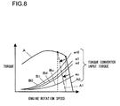
- FIG 8 is a traveling performance diagram (torque diagram) indicating the relationship between the engine rotation speed and the torque.
- Characteristics A in the figure are engine output torque characteristics. More specifically, a characteristics curve A0 represents the engine output torque characteristics manifesting when the engine rotates at the rated rotation speed with the accelerator pedal 11 operated to the maximum extent and a characteristics curve A1 represents the engine output torque characteristics manifesting when the pedal is operated to an extent equivalent to the threshold value AS. The characteristics A1 are equivalent to characteristics achieved by shifting the characteristics A0 toward the lower speed side.
- Curves B0, B1, Bd and Bu in FIG 8 each indicate the torque input to the transmission 3 (transmission torque) when the torque speed ratio e is equal to 0, e1, ed and eu respectively.
- Each transmission torque increases as the engine rotation speed N rises.
- the transmission torque becomes lower as the torque converter speed ratio e takes on a greater value.
- intersection points at which the characteristics curves A0 and A1 and the characteristics curves B0, B1, Bd and Bu intersect are matching points and the engine rotation speed is represented by the value assumed at a matching point.
- the target engine rotation speed is lowered from the rated rotation speed to the threshold value Na, the maximum vehicle speed and the acceleration performance at each gear setting are suppressed by the extent corresponding to the decrease in the engine rotation speed. This means that energy-saving operation can be achieved if the operator ensures that the accelerator pedal operation quantity is kept equal to or less than the preset value AS.
- FIG 9 presents a flowchart of an example of processing that may be executed by the controller 10.
- the processing in the flowchart may start as, for instance, an engine key switch is turned on.
- step S1 the signals provided by the various detectors 12 through 15 and the switches 7 through 9 are read.
- step S2 a decision is made as to whether or not the accelerator pedal operation quantity S, detected via the operation quantity detector 12, is equal to or less than the preset value AS, i.e., whether or not the target engine rotation speed is equal to or less than the threshold value Na.
- step S2 If an affirmative decision is made in step S2, the operation proceeds to step S3, in which a decision is made as to whether or not the torque converter speed ratio e, calculated based upon the values Ni and Nt detected via the rotation speed detector 14 and the rotation speed detector 15 respectively, is equal to or greater than the predetermined value e1. If an affirmative decision is made in step S3, the operation proceeds to step S4 to start counting time on a timer.
- step S5 a decision is made as to whether or not the state in which the pedal operation quantity S is equal to or less than the preset value AS and the torque converter speed ratio e is equal to or greater than the predetermined value e1 has been sustained over a predetermined length of time t0, i.e., whether or not a fuel efficiency deteriorating condition exists. If an affirmative decision is made in step S5, it is judged that the fuel efficiency deteriorating condition does not exist and the operation proceeds to step S6, whereas if a negative decision is made in step S5, the operation returns to step S1.
- step S6 a control signal is output to the ECO mark display unit 22 to bring up a display of the ECO mark (ECO display).
- step S2 If, on the other hand, it is decided in step S2 that the pedal operation quantity S is greater than the preset value AS or it is decided in step S3 that the torque converter speed ratio e is less than the predetermined value e1, the fuel efficiency deteriorating condition is judged to exist, and the operation proceeds to step S7.
- step S7 the timer is reset. Then, a control signal is output to the ECO mark display unit 22 to turn off the ECO mark display (ECO non-display).
- the primary operations executed in the embodiment may be summarized as follows. If the state in which the pedal operation quantity S remains equal to or less than the preset value AS and the torque converter speed ratio e remains equal to or greater than the predetermined value e1 is sustained over the predetermined length of time t0, the ECO mark is displayed at the ECO mark display unit 22 (step S6). With the ECO mark display brought up in this manner the operator is informed that the energy-saving operation is ongoing. If the pedal operation quantity S exceeds the preset value AS while the torque converter speed ratio e remains equal to or greater than the predetermined value e1, the ECO mark is taken off display.
- the ECO mark is taken off display even if the pedal operation quantity S is equal to or less than the preset value AS. This lets the operator know that the vehicle is engaged in operation with poor torque converter efficiency ⁇ .
- the operator may shift the gear setting down to first gear by operating the shift switch 8 or the kick-down switch 34, so as to improve the torque converter efficiency ⁇ .
- the ECO mark will be brought up on display to indicate that the energy-saving operation has been resumed.
- the torque converter efficiency ⁇ when the torque converter efficiency ⁇ is low, the motive power loss occurring within the torque converter is significant and the engine 1 consumes fuel at a higher rate.
- the pedal operation quantity S remains equal to or less than the preset value AS, the vehicle is not really engaged in energy-saving operation and that the gear setting needs to be shifted down in order to achieve the energy-saving operation state.
- the ECO mark is brought up on display or the ECO mark display is turned off to indicate to the operator whether or not the torque converter efficiency ⁇ is poor, which allows the operator to shift the gear setting down with optimal timing and ultimately facilitates energy-saving operation.
- the fuel efficiency deteriorating condition does not exist, i.e., the fuel efficiency deteriorating condition is judged to have cleared, only if the state in which the torque converter speed ratio e remains equal to or greater than the predetermined value e1 and the target engine rotation speed remains above the preset value Na over a period of time longer than the predetermined length of time t0.
- stable display is provided at the ECO mark display unit 22, enabling the operator to make an accurate decision with regard to whether or not the vehicle is currently engaged in energy-saving operation.
- the ECO mark display is not kept off within the regular automatic gear shift range, as long as the pedal operation quantity S remains equal to or less than the predetermined value AS and instead, the ECO mark display is kept off only if a manual downshift is required.
- the work vehicle control device achieved in the second embodiment is now described.
- the work vehicle control device achieved in the second embodiment is distinguishable from the work vehicle control device in the first embodiment only in the processing executed by the controller 10. Since the other structural features of the second embodiment are identical to those of the first embodiment, a repeated explanation is not provided and the following explanation focuses on the processing executed by the controller 10.
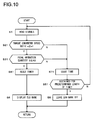
- FIG 10 presents a flowchart of the processing executed by the controller 10 in the second embodiment.
- FIG 10 corresponds to FIG 9 pertaining to the first embodiment.
- the same step numbers are assigned to steps in which processing similar to that executed in the first embodiment, as shown in FIG 9 is executed.
- the processing executed as shown in the flowchart starts as, for instance, the engine key switch is turned on.
- step S1 the signals provided by the various detectors 12 through 15 and the switches 7 through 9 are read.
- step S21 a decision is made as to whether or not the torque converter speed ratio e, calculated based upon the values Ni and Nt detected by the rotation speed detector 14 and the rotation speed detector 15, is equal to or greater than the predetermined value e1.
- step S21 If an affirmative decision is made in step S21, the operation proceeds to step S31 to make a decision as to whether or not the accelerator pedal operation quantity S, detected by the operation quantity detector 12, is equal to or less than the preset value AS, i.e., whether or not the target engine rotation speed is equal to or less than the threshold value Na. If an affirmative decision is made in step S31, the operation proceeds to step S41. In step S41, the timer is reset. In step S6, a control signal is output to the ECO mark display unit 22 to bring up a display of the ECO mark (ECO display).
- step S21 If, on the other hand, it is decided in step S21 and that the torque converter speed ratio e is less than the predetermined value e1 or if it is decided in step S31 that the pedal operation quantity S is greater than the preset value AS, the operation proceeds to step S71.
- step S71 time is counted on the timer.
- step S51 a decision is made as to whether or not the state in which the torque converter speed ratio e remains less than the predetermined value e1 or the state in which the torque converter speed ratio e is equal to or greater than the predetermined value e1 but the accelerator pedal operation quantity S is greater than the preset value AS has been sustained over a predetermined length of time t0.
- step S51 If an affirmative decision is made in step S51, the fuel efficiency deteriorating condition is judged to exist and the operation proceeds to step S8, but if a negative decision is made in step S51, the operation returns to step S1.
- step S8 a control signal is output to the ECO mark display unit 22 to leave the ECO mark display off (ECO non-display).
- the fuel efficiency deteriorating condition is judged to exist if the state in which the torque converter speed ratio e remains less than the predetermined value e1 is sustained over a period of time equal to or longer than the predetermined time length t0 or if the state in which the torque converter speed ratio e is equal to or greater than the predetermined value e1 and the target engine rotation speed remains higher than the preset value Na is sustained over a period of time equal to or greater than the predetermined time length t0.
- stable display is provided at the ECO mark display unit 22, enabling the operator to make an accurate decision as to whether or not the vehicle is currently engaged in energy-saving operation.
- control device provides information indicating whether or not the fuel efficiency deteriorating condition exists by either displaying the ECO mark or keeping the ECO mark display turned off
- an informing means adopting a structure other than that described above may be used to indicate whether or not the fuel efficiency deteriorating condition exists. For instance, a warning sound may be output to indicate that the fuel efficiency deteriorating condition exists.
- the fuel efficiency deteriorating condition may be judged to exist when the torque converter speed ratio e is less than the predetermined value e1 or when the torque converter speed ratio e is equal to or greater than the predetermined value e1 and the target engine rotation speed remains higher than the preset value Na, processing other than that described above may be executed by the controller 10 functioning as the decision-making means. Namely, the fuel efficiency deteriorating condition may be judged to exist without making a decision as to whether or not a specific state is sustained over a predetermined length of time t. Furthermore, when the fuel efficiency deteriorating condition exists, a message indicating a poor fuel efficiency condition may be displayed or a sound (a voice, an alarm or the like) indicating a poor fuel efficiency condition may be output, instead of turning off the ECO mark display.
- the automatic gear shift means may adopt a structure different from this.
- the gear setting at the transmission 3 is adjusted within the range of first through fourth gears in response to an operation of the shift switch 8 in the manual gear shift mode
- the manual gear shift means adopting a structure other than this may be used in the manual gear shift mode.
- a value smaller than the torque converter speed ratio ed used as the downshift reference value is set as the predetermined value e1
- the predetermined value e1 may be set to a value other than this.
- a rotation speed control means adopting a structure other than that described above may be used, as long as it controls the engine rotation speed in correspondence to the extent to which the accelerator pedal 11 is operated. Furthermore, while the rotation of the engine 1 is transmitted to the tires 6 via the torque converter 2, the transmission 3, the drive shaft 4 and the axles 5, a traveling drive device assuming any structure may be used in conjunction with the present invention. Moreover, while the torque converter speed ratio e is detected based upon the values detected via the rotation speed detectors 14 and 15, a speed ratio detection means adopting a structure other than this may be used in conjunction with the present invention.
- the present invention is not limited to this example and it may be adopted equally effectively in other types of work vehicles. Namely, as long as the features characterizing the present invention and the functions of the present invention are fulfilled, the present invention is not limited in any way whatsoever to the control devices described in reference to the embodiments.
Abstract
Description
- The present invention relates to a work vehicle control device that controls a work vehicle equipped with a torque converter, such as a wheel loader.
- There are devices known in the related art that prompt an operator driving a vehicle to operate the vehicle in a manner that improves fuel efficiency (see, for instance, patent literature 1). The device disclosed in
patent literature 1 compares the actual fuel consumption with a specific target value and issues an alarm if the real fuel consumption is judged to be greater than the target value. The real fuel consumption is calculated by dividing the fuel consumption quantity by the traveling distance over which the vehicle has traveled. - Patent Literature 1: Japanese Laid Open Patent Publication No.
H4-366729 - However, since a work vehicles such as a wheel loader is engaged in work as it travels, it is difficult to improve fuel efficiency throughout the overall work operation simply through high-efficiency operation that is prompted in reference to the real fuel consumption calculated by dividing the fuel consumption quantity by the traveling distance.
- According to the 1st aspect of the present invention, a work vehicle control device comprises: a rotation speed control unit that controls a rotation speed of an engine in correspondence to an accelerator pedal operation quantity indicating an extent to which an accelerator pedal is operated; a speed ratio detection unit that detects a speed ratio of a speed at an input shaft and a speed at an output shaft of a torque converter, which is disposed between the engine and wheels to transmit rotation of the engine to the wheels; a decision-making unit that makes a decision that a fuel efficiency deteriorating condition exists if the torque converter speed ratio detected via the speed ratio detection unit is less than a predetermined value or if the torque converter speed ratio detected via the speed ratio detection unit is equal to or greater than the predetermined value and a target engine rotation speed corresponding to an operation of the accelerator pedal is greater than a preset value; and an informing unit that informs results of the decision made by the decision-making unit.
According to the 2nd aspect of the present invention, in the work vehicle control device according to the 1st aspect, it is preferred that the informing unit includes a display device at a location within an operator's cab, that displays the results of the decision made by the decision-making unit.
According to the 3rd aspect of the present invention, in the work vehicle control device according to the 1st or the 2nd aspect, it is preferred that the decision-making unit makes the decision that the fuel efficiency deteriorating condition exists if a state in which the torque converter speed ratio remains less than the predetermined value is sustained over a period of time equal to or longer than a predetermined time length or if a state in which the torque converter speed ratio is equal to or greater than the predetermined value and the target engine rotation speed remains higher than the preset value is sustained over a period of time equal to or greater than a predetermined time length.
According to the 4th aspect of the present invention, in the work vehicle control device according to any one of the 1st through the 3rd aspects, it is preferred that: the work vehicle control device further comprises an automatic gear shift control unit that adjusts a gear setting at a transmission in correspondence to the speed ratio detected by the speed ratio detection unit, over a range in which a gear larger than first gear is set as a minimum gear, and a manual gear shift control unit that adjusts the gear setting at the transmission in response to a manual operation over a range that includes first gear and larger gears; and the automatic gear shift control unit shifts down the gear setting if the torque converter speed ratio decreases to a downshift reference value that is greater than the predetermined value. - According to the present invention, if the torque converter speed ratio is less than a predetermined value or if the torque converter speed ratio is equal to or greater than the predetermined value and the target engine rotation speed, indicated by the accelerator pedal operation position, is greater than a preset value, it is decided that a fuel efficiency deteriorating condition exists and the decision-making results are reported to the operator. As a result, the operator is prompted to operate the work vehicle with better fuel efficiency throughout the entire work operation.
-
- (
FIG 1 ) A side elevation of a wheel loader representing an example of a work vehicle pertaining to an embodiment of the present invention - (
FIG 2 ) A schematic block diagram of the control device achieved in the embodiment of the present invention - (
FIG 3 ) A plan view of the interior of the operator's cab provided in (a) and a front view of the operation levers provided in (b) - (
FIG 4 ) A diagram indicating the gear shift timing with which gears are shifted in reference to the torque converter speed ratio - (
FIG 5 ) A graph indicating the relationship between the torque converter speed ratio and the torque converter efficiency - (
FIG 6 ) A diagram indicating the relationship between the vehicle speed at each gear setting and the traveling drive force - (
FIG 7 ) A diagram indicating the relationship between the accelerator pedal operation position and the target engine rotation speed - (
FIG 8 ) A diagram indicating the torque characteristics achieved via the control device in the embodiment - (
FIG 9 ) A flowchart of an example of processing that may be executed by the controller inFIG 2 - (
FIG 10 ) A flowchart of an example of processing that may be executed by the controller achieved in a second embodiment - In reference to
FIGS. 1 through 9 , the work vehicle control device achieved in the first embodiment of the present invention is described.
FIG 1 is a side elevation of a wheel loader, representing an example of a work vehicle in conjunction with which the control device achieved in the embodiment may be adopted. Awheel loader 100 is constituted with afront body 110 at which anarm 111, abucket 112,tires 113, and the like are disposed and arear body 120, at which an operator'scab 121, anengine room 122,tires 123 and the like are disposed. Thearm 111 swings up/down (ascends/descends) as anarm cylinder 114 is driven, whereas thebucket 112 swings up/down (crowds/dumps) as abucket cylinder 115 is driven. Thefront body 110 and therear body 120 are linked via acenter pin 101 so as to be allowed to rotate relative to each other and, as a steering cylinder (not shown) extends/contracts, thefront body 110 swivels to the left/right relative to therear body 120. -
FIG 2 schematically illustrates the structure of the control device achieved in the embodiment. An input shaft of atorque converter 2 is connected to an output shaft of anengine 1, whereas an output shaft of thetorque converter 2 is connected to atransmission 3. Thetorque converter 2 is a fluid clutch constituted with an impeller, a turbine and a stator of the known art, and the rotation of theengine 1 is transmitted to thetransmission 3 via thetorque converter 2. Thetransmission 3 includes a fluid clutch via which its gear setting is shifted, and the rotation speed of the output shaft of thetorque converter 2 is altered via thetransmission 3. The rotation, the speed of which has been altered, is transmitted to tires 6 (thetires FIG 1 ) via a drive shaft 4 andaxles 5, thereby engaging the vehicle in traveling operation. It is to be noted that although not shown, a work hydraulic pump, which is driven by theengine 1, is connected to the output shaft of theengine 1. Pressure oil is delivered from the work hydraulic pump to a work actuator (such as the arm cylinder or the like) in a quantity corresponding to the extent to which an operation lever is operated and the work actuator is driven with the pressure oil delivered from the hydraulic pump. - A
controller 10 includes an arithmetic processing device constituted with a CPU, a ROM, a RAM and other peripheral circuits. Signals provided by anoperation quantity detector 12 that detects an operation quantity S indicating the extent to which anaccelerator pedal 11 is operated, avehicle speed detector 13 that detects the rotation speed of the output shaft of thetransmission 3, i.e., the vehicle speed, arotation speed detector 14 that detects a rotation speed Ni at the input shaft of thetorque converter 2, arotation speed detector 15 that detects a rotation speed Nt at the output shaft of thetorque converter 2, the shiftmode selector switch 7 that selects either a manual shift mode, in which gears are shifted manually, or an automatic shift mode, in which gears are shifted automatically, ashift switch 8 via which an upper limit gear setting for the automatic gear shift mode is specified and a gear setting for the manual gear shift mode is specified, and a forward/reverse changeover switch 9 that issues a forward/reverse command for the vehicle, are input to thecontroller 10. -
FIG 3(a) shows the interior of the operator's cab in a plan view. The gear shiftmode selector switch 7 is disposed at aside console panel 31 located to the right of a driver'sseat 30. To the front of theside console panel 31, a pair of operation levers 32, via which work actuator drive commands are input, are disposed. To one side of the steering wheel, theshift switch 8 and the forward/reverse changeover switch 9 are disposed. Amonitor panel 33 is disposed to the front of the driver'sseat 30, includes an ECO (ecological operation)mark display unit 22 used to indicate whether or not the vehicle is currently engaged in energy-saving operation (eco-friendly operation). An ECO mark is displayed at the ECOmark display unit 22 when the vehicle is engaged in eco-friendly operation, whereas the ECO mark is not displayed in the ECOmark display unit 22 when the vehicle is engaged in operation other than the eco-friendly operation. As shown inFIG. 3(b) , a momentary-type kick-down switch 34, via which a manual downshift command is issued, is disposed at the top of the handle of anoperation lever 32. - The
torque converter 2 has a function of increasing the output torque relative to the input torque, i.e., a function of achieving a torque ratio of 1 or more. The torque ratio assumes a smaller value as a torque converter speed ratio e (output rotation speed Nt/input rotation speed Ni), representing the ratio of the rotation speed of the input shaft and the rotation speed of the output shaft of thetorque converter 2, increases. For instance, as the traveling load increases while the vehicle is traveling at a steady engine rotation speed, the output rotation speed Nt of thetorque converter 2, i.e., the vehicle speed decreases, and the torque converter speed ratio e, too, decreases. Under these circumstances, the torque ratio increases, which allows the vehicle to travel with a greater drive force (tractor force). - The
transmission 3 is an automatic gear shift unit that includes solenoid valves disposed each in correspondence to one of the various gear settings, first through fourth gears. These solenoid valves are driven by a control signal output from thecontroller 10 to asolenoid control unit 21. In other words, as a control signal (an upshift signal or a downshift signal) is output from thecontroller 10, thesolenoid control unit 21 outputs a control signal corresponding to the control signal to the solenoid valves so as to drive the solenoid valves. Through this control, the gear setting is automatically adjusted to a setting in the second through fourth gear range in the automatic gear shift mode. It is to be noted that the first gear cannot be automatically switched to the second gear or vice versa. In other words, the gear setting can be shifted from first gear to second gear or vice versa only manually. - Automatic gear shift control may be executed either by adopting a torque converter speed ratio-based control method, whereby a gear shift is effected when the torque converter speed ratio e reaches a predetermined value or a vehicle speed-based control method whereby a gear shift is effected when the vehicle speed reaches a predetermined value. The embodiment is described by assuming that the gear setting at the
transmission 3 is controlled through the torque converter speed ratio-based control method. -
FIG 4 is a diagram indicating the gear shift timing with which the gear shift is effected under torque converter speed ratio-based control. As the traveling load becomes lower and the torque converter speed ratio e increases to a value equal to or greater than a predetermined specific value eu, an upshift signal is output by thecontroller 10. As a result, a gear setting shifts up by one stage, resulting in a reduction in the torque converter speed ratio e. In contrast, as the traveling load increases and the torque converter speed ratio e decreases to a value equal to or less than a predetermined specific value ed, the controller outputs a downshift signal. In response, the gear setting shifts down by one stage to result in an increase in the torque converter speed ratio e. - The automatic gear shift in the embodiment is executed by designating the gear setting selected via the
shift switch 8 as the upper limit. For instance, if third gear is selected via theshift switch 8, the gear setting is switched to second gear or third gear, whereas if second gear is selected via theshift switch 8, the gear setting remains fixed at second gear. If first gear is selected via theshift switch 8, or if the kick-down switch 34 is operated while in second gear, the gear setting is switched to first gear. -
FIG 5 indicates the relationship between the torque converter speed ratio e and the torque converter efficiency. AsFIG 5 indicates, the torque converter efficiency characteristics are represented by a substantially parabolic curve and the efficiency η becomes poorer when the torque converter speed ratio e takes on a value close to 0 or close to 1. In the embodiment, the specific values ed and eu are selected so as to execute automatic gear shift over a range within which the torque converter efficiency η assumes relatively large values. In addition, a predetermined speed ratio value e1 (< ed) is set, and if the torque converter speed ratio e becomes less than the predetermined value e1, a control signal is output to the ECOmark display unit 22 so as to warn the operator that the vehicle is currently operating with poor fuel efficiency. It is to be noted that when the torque converter efficiency η is poor, the fuel efficiency is compromised and furthermore, since the fuel consumption quantity is large, the engine cooling water temperature and the torque converter oil temperature rise, leading to a condition in which overheating occurs readily. - The relationship between the vehicle speed at each gear setting and the drive force is indicated in
FIG 6 . AsFIG. 6 clearly shows, at any given gear setting, greater drive force is imparted at a lower vehicle speed (low speed and high torque) and the drive force decreases at a higher vehicle speed (high-speed and low torque). In addition, at a given vehicle speed, greater drive force can be achieved at a lower gear setting. The point at which the lines representing the second gear characteristics and the third gear characteristics intersect and the point at which the lines representing the third gear characteristics and the fourth gear characteristics intersect are gear shift points. The predetermined values ed and eu inFIG 4 are set at these intersection points. As a result, smooth gear shift operation with a minimum of shift shock is enabled. It is to be noted that while automatic gear shift is executed over the range, with the lower limit thereof is set at second gear in the embodiment, first gear may also be included in the automatic gear shift range, and in such a case, predetermined values ed and eu should also be set at the intersection point where the lines representing the first gear characteristics and the second gear characteristics intersect, as shown in the figure. -
FIG 7 is a diagram indicating the relationship between the operation quantity representing the extent to which theaccelerator pedal 11 has been operated, and the target engine rotation speed. As the operation quantity at theaccelerator pedal 11 increases, the target engine rotation speed rises, and a rated rotation is achieved at the target engine rotation speed corresponding to the maximum accelerator pedal operation quantity. Thecontroller 10 outputs a control signal corresponding to the target engine rotation speed to an engine control unit, so as to execute control under which the engine rotation speed is adjusted to the target engine rotation speed. - In the embodiment, a threshold value Na (e.g., 80% of the rated rotation speed) to be used as an energy-saving operation reference value, is set in advance so as to prompt the operator to drive the
engine 1 at a desirable fuel consumption rate. The pedal operation quantity AS corresponding to the threshold value Na and the actual pedal operation quantity S are compared with each other and the operator is advised to execute energy-saving operation depending upon the comparison results. Control is executed by taking into consideration the torque converter efficiency η as well, as described later. -
FIG 8 is a traveling performance diagram (torque diagram) indicating the relationship between the engine rotation speed and the torque. Characteristics A in the figure are engine output torque characteristics. More specifically, a characteristics curve A0 represents the engine output torque characteristics manifesting when the engine rotates at the rated rotation speed with theaccelerator pedal 11 operated to the maximum extent and a characteristics curve A1 represents the engine output torque characteristics manifesting when the pedal is operated to an extent equivalent to the threshold value AS. The characteristics A1 are equivalent to characteristics achieved by shifting the characteristics A0 toward the lower speed side. - Curves B0, B1, Bd and Bu in
FIG 8 each indicate the torque input to the transmission 3 (transmission torque) when the torque speed ratio e is equal to 0, e1, ed and eu respectively. Each transmission torque increases as the engine rotation speed N rises. In addition, the transmission torque becomes lower as the torque converter speed ratio e takes on a greater value. - The intersection points at which the characteristics curves A0 and A1 and the characteristics curves B0, B1, Bd and Bu intersect are matching points and the engine rotation speed is represented by the value assumed at a matching point. As the target engine rotation speed is lowered from the rated rotation speed to the threshold value Na, the maximum vehicle speed and the acceleration performance at each gear setting are suppressed by the extent corresponding to the decrease in the engine rotation speed. This means that energy-saving operation can be achieved if the operator ensures that the accelerator pedal operation quantity is kept equal to or less than the preset value AS.
-
FIG 9 presents a flowchart of an example of processing that may be executed by thecontroller 10. The processing in the flowchart may start as, for instance, an engine key switch is turned on. In step S1, the signals provided by thevarious detectors 12 through 15 and theswitches 7 through 9 are read. In step S2, a decision is made as to whether or not the accelerator pedal operation quantity S, detected via theoperation quantity detector 12, is equal to or less than the preset value AS, i.e., whether or not the target engine rotation speed is equal to or less than the threshold value Na. - If an affirmative decision is made in step S2, the operation proceeds to step S3, in which a decision is made as to whether or not the torque converter speed ratio e, calculated based upon the values Ni and Nt detected via the
rotation speed detector 14 and therotation speed detector 15 respectively, is equal to or greater than the predetermined value e1. If an affirmative decision is made in step S3, the operation proceeds to step S4 to start counting time on a timer. In step S5, a decision is made as to whether or not the state in which the pedal operation quantity S is equal to or less than the preset value AS and the torque converter speed ratio e is equal to or greater than the predetermined value e1 has been sustained over a predetermined length of time t0, i.e., whether or not a fuel efficiency deteriorating condition exists. If an affirmative decision is made in step S5, it is judged that the fuel efficiency deteriorating condition does not exist and the operation proceeds to step S6, whereas if a negative decision is made in step S5, the operation returns to step S1. In step S6, a control signal is output to the ECOmark display unit 22 to bring up a display of the ECO mark (ECO display). - If, on the other hand, it is decided in step S2 that the pedal operation quantity S is greater than the preset value AS or it is decided in step S3 that the torque converter speed ratio e is less than the predetermined value e1, the fuel efficiency deteriorating condition is judged to exist, and the operation proceeds to step S7. In step S7, the timer is reset. Then, a control signal is output to the ECO
mark display unit 22 to turn off the ECO mark display (ECO non-display). - The primary operations executed in the embodiment may be summarized as follows. If the state in which the pedal operation quantity S remains equal to or less than the preset value AS and the torque converter speed ratio e remains equal to or greater than the predetermined value e1 is sustained over the predetermined length of time t0, the ECO mark is displayed at the ECO mark display unit 22 (step S6). With the ECO mark display brought up in this manner the operator is informed that the energy-saving operation is ongoing. If the pedal operation quantity S exceeds the preset value AS while the torque converter speed ratio e remains equal to or greater than the predetermined value e1, the ECO mark is taken off display. This lets the operator know that he is stepping on the
accelerator pedal 11 to an excessive extent and thus prompts the operator to switch to energy-saving operation by backing off on the operation of theaccelerator pedal 11 so that the accelerator pedal operation quantity is kept equal to or less than the preset value AS. - As the torque converter speed ratio e becomes less than the predetermined value e1 while the vehicle is traveling uphill or is engaged in excavating operation on a steep hill with a high traveling load in second gear, the ECO mark is taken off display even if the pedal operation quantity S is equal to or less than the preset value AS. This lets the operator know that the vehicle is engaged in operation with poor torque converter efficiency η. In response, the operator may shift the gear setting down to first gear by operating the
shift switch 8 or the kick-down switch 34, so as to improve the torque converter efficiency η. As the torque conversion efficiency η improves, the ECO mark will be brought up on display to indicate that the energy-saving operation has been resumed. - Namely, when the torque converter efficiency η is low, the motive power loss occurring within the torque converter is significant and the
engine 1 consumes fuel at a higher rate. This means that even if the pedal operation quantity S remains equal to or less than the preset value AS, the vehicle is not really engaged in energy-saving operation and that the gear setting needs to be shifted down in order to achieve the energy-saving operation state. In the embodiment, the ECO mark is brought up on display or the ECO mark display is turned off to indicate to the operator whether or not the torque converter efficiency η is poor, which allows the operator to shift the gear setting down with optimal timing and ultimately facilitates energy-saving operation. - The following advantages are achieved through the embodiment.
- (1) The ECO mark display at the ECO
mark display unit 22 is off if the target engine rotation speed corresponding to the extent to which theaccelerator pedal 11 is operated, is greater than the preset value Na or if the target engine rotation speed is equal to or less than the preset value Na but the torque converter speed ratio e is less than the predetermined value e1 (if the fuel efficiency deteriorating condition exists). Thus, the operator is able to ascertain with ease whether or not the vehicle is currently engaged in energy-saving operation and is able to shift into energy-saving operation if necessary. Even when the torque converter speed ratio e is equal to or greater than the predetermined value e1, the fuel efficiency deteriorating condition is judged to exist if the target engine rotation speed corresponding to the extent to which theaccelerator pedal 11 is operated, is greater than the preset value Na, and the ECO mark display at the ECOmark display unit 22 is off under such circumstances. - (2) Since the decision as to whether or not the fuel efficiency deteriorating condition exists is made in reference to the extent to which the
accelerator pedal 11 is operated and the torque converter speed ratio e and the decision-making results are reflected in the display provided at the ECOmark display unit 22, the operator is prompted to operate the vehicle with better fuel efficiency throughout the entire work operation. - (3) With the ECO mark display brought up depending upon whether or not the fuel efficiency deteriorating condition exists, the operator is able to determine with ease whether or not the vehicle is currently engaged in energy-saving operation.
- (4) It is decided that the fuel efficiency deteriorating condition does not exist, i.e., the fuel efficiency deteriorating condition is judged to have cleared, only if the state in which the torque converter speed ratio e remains equal to or greater than the predetermined value e1 and the target engine rotation speed remains above the preset value Na over a period of time longer than the predetermined length of time t0. This means that stable display is provided at the ECO
mark display unit 22, enabling the operator to make an accurate decision with regard to whether or not the vehicle is currently engaged in energy-saving operation. - (5) Since the lowest gear setting in the automatic gear shift range is second gear, no automatic downshift is executed to switch from second gear to first gear, thereby assuring better operability.
- (6) Since the predetermined value e1 is set so as to assume a lower value than the torque converter speed ratio ed used as the downshift reference value, the ECO mark display is not kept off within the regular automatic gear shift range, as long as the pedal operation quantity S remains equal to or less than the predetermined value AS and instead, the ECO mark display is kept off only if a manual downshift is required.
- The work vehicle control device achieved in the second embodiment is now described. The work vehicle control device achieved in the second embodiment is distinguishable from the work vehicle control device in the first embodiment only in the processing executed by the
controller 10. Since the other structural features of the second embodiment are identical to those of the first embodiment, a repeated explanation is not provided and the following explanation focuses on the processing executed by thecontroller 10. -
FIG 10 presents a flowchart of the processing executed by thecontroller 10 in the second embodiment.FIG 10 corresponds toFIG 9 pertaining to the first embodiment. InFIG. 10 , the same step numbers are assigned to steps in which processing similar to that executed in the first embodiment, as shown inFIG 9 is executed. - As in the first embodiment, the processing executed as shown in the flowchart starts as, for instance, the engine key switch is turned on. In step S1, the signals provided by the
various detectors 12 through 15 and theswitches 7 through 9 are read. In step S21, a decision is made as to whether or not the torque converter speed ratio e, calculated based upon the values Ni and Nt detected by therotation speed detector 14 and therotation speed detector 15, is equal to or greater than the predetermined value e1. - If an affirmative decision is made in step S21, the operation proceeds to step S31 to make a decision as to whether or not the accelerator pedal operation quantity S, detected by the
operation quantity detector 12, is equal to or less than the preset value AS, i.e., whether or not the target engine rotation speed is equal to or less than the threshold value Na. If an affirmative decision is made in step S31, the operation proceeds to step S41. In step S41, the timer is reset. In step S6, a control signal is output to the ECOmark display unit 22 to bring up a display of the ECO mark (ECO display). - If, on the other hand, it is decided in step S21 and that the torque converter speed ratio e is less than the predetermined value e1 or if it is decided in step S31 that the pedal operation quantity S is greater than the preset value AS, the operation proceeds to step S71. In step S71, time is counted on the timer. In step S51, a decision is made as to whether or not the state in which the torque converter speed ratio e remains less than the predetermined value e1 or the state in which the torque converter speed ratio e is equal to or greater than the predetermined value e1 but the accelerator pedal operation quantity S is greater than the preset value AS has been sustained over a predetermined length of time t0. If an affirmative decision is made in step S51, the fuel efficiency deteriorating condition is judged to exist and the operation proceeds to step S8, but if a negative decision is made in step S51, the operation returns to step S1. In step S8, a control signal is output to the ECO
mark display unit 22 to leave the ECO mark display off (ECO non-display). - The following advantages are achieved through the embodiment.
- (1) If the torque converter speed ratio e is less than the predetermined value e1 or if the torque converter speed ratio e is equal to or greater than the predetermined value e1 and the target engine rotation speed corresponding to the extent to which the
accelerator pedal 11 is operated, is greater than the preset value Na (if the fuel efficiency deteriorating condition exists), the ECO mark display at the ECOmark display unit 22 is off. As a result, the operator is able to ascertain with ease whether or not the vehicle is currently engaged in energy-saving operation and is able to shift into energy-saving operation if necessary. - (2) The fuel efficiency deteriorating condition is judged to exist if the state in which the torque converter speed ratio e remains less than the predetermined value e1 is sustained over a period of time equal to or longer than the predetermined time length t0 or if the state in which the torque converter speed ratio e is equal to or greater than the predetermined value e1 and the target engine rotation speed remains higher than the preset value Na is sustained over a period of time equal to or greater than the predetermined time length t0. As a result, stable display is provided at the ECO
mark display unit 22, enabling the operator to make an accurate decision as to whether or not the vehicle is currently engaged in energy-saving operation. - In addition to the advantages listed above, advantages similar to those of the first embodiment are achieved through the embodiment.
- It is to be noted that while the control device provides information indicating whether or not the fuel efficiency deteriorating condition exists by either displaying the ECO mark or keeping the ECO mark display turned off, at the ECO
mark display unit 22 in either of the embodiments described above, an informing means adopting a structure other than that described above may be used to indicate whether or not the fuel efficiency deteriorating condition exists. For instance, a warning sound may be output to indicate that the fuel efficiency deteriorating condition exists. In addition, as long as the fuel efficiency deteriorating condition is judged to exist when the torque converter speed ratio e is less than the predetermined value e1 or when the torque converter speed ratio e is equal to or greater than the predetermined value e1 and the target engine rotation speed remains higher than the preset value Na, processing other than that described above may be executed by thecontroller 10 functioning as the decision-making means. Namely, the fuel efficiency deteriorating condition may be judged to exist without making a decision as to whether or not a specific state is sustained over a predetermined length of time t. Furthermore, when the fuel efficiency deteriorating condition exists, a message indicating a poor fuel efficiency condition may be displayed or a sound (a voice, an alarm or the like) indicating a poor fuel efficiency condition may be output, instead of turning off the ECO mark display. - While the gear setting at the
transmission 3 is adjusted in correspondence to the torque converter speed ratio e in the range of second through fourth gears in the automatic gear shift mode, the automatic gear shift means may adopt a structure different from this. In addition, while the gear setting at thetransmission 3 is adjusted within the range of first through fourth gears in response to an operation of theshift switch 8 in the manual gear shift mode, the manual gear shift means adopting a structure other than this may be used in the manual gear shift mode. While a value smaller than the torque converter speed ratio ed used as the downshift reference value is set as the predetermined value e1, the predetermined value e1 may be set to a value other than this. - A rotation speed control means adopting a structure other than that described above may be used, as long as it controls the engine rotation speed in correspondence to the extent to which the
accelerator pedal 11 is operated. Furthermore, while the rotation of theengine 1 is transmitted to thetires 6 via thetorque converter 2, thetransmission 3, the drive shaft 4 and theaxles 5, a traveling drive device assuming any structure may be used in conjunction with the present invention. Moreover, while the torque converter speed ratio e is detected based upon the values detected via therotation speed detectors - While the explanation is given above on an example in which the present invention is adopted in a wheel loader, the present invention is not limited to this example and it may be adopted equally effectively in other types of work vehicles. Namely, as long as the features characterizing the present invention and the functions of the present invention are fulfilled, the present invention is not limited in any way whatsoever to the control devices described in reference to the embodiments.
- The disclosure of the following priority application is herein incorporated by reference:
- Japanese Patent Application No.
2009-146199, filed June 19, 2009
Claims (4)
- A work vehicle control device, comprising:a rotation speed control unit that controls a rotation speed of an engine in correspondence to an accelerator pedal operation quantity indicating an extent to which an accelerator pedal is operated;a speed ratio detection unit that detects a speed ratio of a speed at an input shaft and a speed at an output shaft of a torque converter, which is disposed between the engine and wheels to transmit rotation of the engine to the wheels;a decision-making unit that makes a decision that a fuel efficiency deteriorating condition exists if the torque converter speed ratio detected via the speed ratio detection unit is less than a predetermined value or if the torque converter speed ratio detected via the speed ratio detection unit is equal to or greater than the predetermined value and a target engine rotation speed corresponding to an operation of the accelerator pedal is greater than a preset value; andan informing unit that informs results of the decision made by the decision-making unit.
- A work vehicle control device according to claim 1, wherein:the informing unit includes a display device at a location within an operator's cab, that displays the results of the decision made by the decision-making unit.
- A work vehicle control device according to claim 1 or claim 2, wherein:the decision-making unit makes the decision that the fuel efficiency deteriorating condition exists if a state in which the torque converter speed ratio remains less than the predetermined value is sustained over a period of time equal to or longer than a predetermined time length or if a state in which the torque converter speed ratio is equal to or greater than the predetermined value and the target engine rotation speed remains higher than the preset value is sustained over a period of time equal to or greater than a predetermined time length.
- A work vehicle control device according to any one of claims 1 through 3, further comprising:an automatic gear shift control unit that adjusts a gear setting at a transmission in correspondence to the speed ratio detected by the speed ratio detection unit, over a range in which a gear larger than first gear is set as a minimum gear; anda manual gear shift control unit that adjusts the gear setting at the transmission in response to a manual operation over a range that includes first gear and larger gears, wherein:the automatic gear shift control unit shifts down the gear setting if the torque converter speed ratio decreases to a downshift reference value that is greater than the predetermined value.
Applications Claiming Priority (2)
| Application Number | Priority Date | Filing Date | Title |
|---|---|---|---|
| JP2009146199 | 2009-06-19 | ||
| PCT/JP2010/060372 WO2010147211A1 (en) | 2009-06-19 | 2010-06-18 | Industrial vehicle control device |
Publications (3)
| Publication Number | Publication Date |
|---|---|
| EP2444288A1 true EP2444288A1 (en) | 2012-04-25 |
| EP2444288A4 EP2444288A4 (en) | 2017-07-05 |
| EP2444288B1 EP2444288B1 (en) | 2018-08-08 |
Family
ID=43356526
Family Applications (1)
| Application Number | Title | Priority Date | Filing Date |
|---|---|---|---|
| EP10789584.9A Active EP2444288B1 (en) | 2009-06-19 | 2010-06-18 | Industrial vehicle control device |
Country Status (6)
| Country | Link |
|---|---|
| US (1) | US8744702B2 (en) |
| EP (1) | EP2444288B1 (en) |
| JP (1) | JP5242786B2 (en) |
| KR (1) | KR101664973B1 (en) |
| CN (1) | CN102803023B (en) |
| WO (1) | WO2010147211A1 (en) |
Families Citing this family (8)
| Publication number | Priority date | Publication date | Assignee | Title |
|---|---|---|---|---|
| KR101664973B1 (en) * | 2009-06-19 | 2016-10-19 | 가부시키가이샤 케이씨엠 | Industrial vehicle control device |
| JP5566333B2 (en) * | 2011-05-11 | 2014-08-06 | 日立建機株式会社 | Construction machine control system |
| CN103890281A (en) * | 2011-10-24 | 2014-06-25 | 沃尔沃建造设备有限公司 | Controlling device used to save fuel for construction machinery |
| US8744705B2 (en) * | 2012-03-15 | 2014-06-03 | GM Global Technology Operations LLC | System and method for determining clutch gains in a transmission during a power downshift |
| JP5491561B2 (en) * | 2012-03-26 | 2014-05-14 | 株式会社小松製作所 | Construction machine and method for notifying good or bad operation of construction machine |
| US20140191558A1 (en) * | 2013-01-08 | 2014-07-10 | Caterpillar Inc. | Operator panel for a machine |
| JP6203060B2 (en) | 2014-01-15 | 2017-09-27 | 株式会社小松製作所 | Work vehicle and control method thereof |
| CN106240572A (en) * | 2016-08-03 | 2016-12-21 | 深圳市永兴元科技有限公司 | Driving behavior analysis method and device |
Family Cites Families (16)
| Publication number | Priority date | Publication date | Assignee | Title |
|---|---|---|---|---|
| JPH04208658A (en) * | 1990-11-30 | 1992-07-30 | Mitsubishi Motors Corp | Drive bi-wire type vehicle with car body speed detecting compensatory control unit |
| JP2997097B2 (en) | 1991-06-12 | 2000-01-11 | 株式会社ユニシアジェックス | Vehicle fuel economy warning device |
| DE4320111C2 (en) * | 1993-06-17 | 2003-02-27 | Bosch Gmbh Robert | Method and device for controlling a vehicle |
| US6165102A (en) | 1999-11-22 | 2000-12-26 | Cummins Engine Company, Inc. | System for controlling output torque characteristics of an internal combustion engine |
| JP3656548B2 (en) * | 2000-12-22 | 2005-06-08 | 日産自動車株式会社 | Vehicle driving force control device |
| JP4002455B2 (en) | 2002-03-22 | 2007-10-31 | ミヤマ株式会社 | Vehicle operating state evaluation system |
| JP4125168B2 (en) * | 2003-04-02 | 2008-07-30 | 本田技研工業株式会社 | Vehicle travel control device |
| JP4163073B2 (en) * | 2003-08-12 | 2008-10-08 | 日立建機株式会社 | Control device for work vehicle |
| JP4213545B2 (en) * | 2003-09-05 | 2009-01-21 | 株式会社ジェイテクト | Wheel grip degree estimation device, and vehicle motion control device including the device |
| DE102004024840B4 (en) * | 2004-05-14 | 2007-02-22 | Getrag Getriebe- Und Zahnradfabrik Hermann Hagenmeyer Gmbh & Cie Kg | Method for controlling an automated motor vehicle drive train |
| JP4315248B2 (en) * | 2004-12-13 | 2009-08-19 | 日立建機株式会社 | Control device for traveling work vehicle |
| WO2007072701A1 (en) * | 2005-12-21 | 2007-06-28 | Komatsu Ltd. | Wheel loader |
| JP4345819B2 (en) * | 2007-01-19 | 2009-10-14 | トヨタ自動車株式会社 | Eco-drive support device, eco-drive support method |
| CN101835968B (en) * | 2007-10-24 | 2013-07-24 | 日立建机株式会社 | Engine control device for working vehicle |
| JP5034921B2 (en) | 2007-12-14 | 2012-09-26 | ソニー株式会社 | Information processing apparatus, disk, information processing method, and program |
| KR101664973B1 (en) * | 2009-06-19 | 2016-10-19 | 가부시키가이샤 케이씨엠 | Industrial vehicle control device |
-
2010
- 2010-06-18 KR KR1020117024462A patent/KR101664973B1/en active IP Right Grant
- 2010-06-18 JP JP2011519858A patent/JP5242786B2/en active Active
- 2010-06-18 WO PCT/JP2010/060372 patent/WO2010147211A1/en active Application Filing
- 2010-06-18 CN CN201080026325.7A patent/CN102803023B/en active Active
- 2010-06-18 EP EP10789584.9A patent/EP2444288B1/en active Active
- 2010-06-18 US US13/378,967 patent/US8744702B2/en active Active
Non-Patent Citations (1)
| Title |
|---|
| See references of WO2010147211A1 * |
Also Published As
| Publication number | Publication date |
|---|---|
| KR101664973B1 (en) | 2016-10-19 |
| EP2444288B1 (en) | 2018-08-08 |
| CN102803023B (en) | 2015-03-18 |
| JP5242786B2 (en) | 2013-07-24 |
| US20120089307A1 (en) | 2012-04-12 |
| JPWO2010147211A1 (en) | 2012-12-06 |
| EP2444288A4 (en) | 2017-07-05 |
| US8744702B2 (en) | 2014-06-03 |
| KR20120032461A (en) | 2012-04-05 |
| WO2010147211A1 (en) | 2010-12-23 |
| CN102803023A (en) | 2012-11-28 |
Similar Documents
| Publication | Publication Date | Title |
|---|---|---|
| US8744702B2 (en) | Work vehicle control device | |
| EP2211042B1 (en) | Engine control device for working vehicle | |
| KR101694328B1 (en) | Working vehicle control apparatus | |
| EP2444636B1 (en) | Motor control device for working vehicle | |
| US20120004814A1 (en) | Engine Control Device for Work Vehicle | |
| KR101740745B1 (en) | Apparatus for controlling number of revolutions of engine for industrial vehicle | |
| JP5032705B2 (en) | Engine speed controller and motor grader having the same | |
| KR101744288B1 (en) | System and method for optimizing downshifting of a transmission during vehicle deceleration | |
| US8718879B2 (en) | Work vehicle and method for controlling work vehicle | |
| JP5061120B2 (en) | Shift control device for industrial vehicle | |
| US7472010B2 (en) | Brake-actuating transmission control system | |
| CN107228187A (en) | The speed changer cutting control device and method of engineering machinery | |
| JP5194753B2 (en) | Shift control device for vehicle transmission | |
| JP6200801B2 (en) | Work machine | |
| KR20160133322A (en) | Method and system for controlling wheel loader |
Legal Events
| Date | Code | Title | Description |
|---|---|---|---|
| PUAI | Public reference made under article 153(3) epc to a published international application that has entered the european phase |
Free format text: ORIGINAL CODE: 0009012 |
|
| 17P | Request for examination filed |
Effective date: 20111212 |
|
| AK | Designated contracting states |
Kind code of ref document: A1 Designated state(s): AL AT BE BG CH CY CZ DE DK EE ES FI FR GB GR HR HU IE IS IT LI LT LU LV MC MK MT NL NO PL PT RO SE SI SK SM TR |
|
| DAX | Request for extension of the european patent (deleted) | ||
| RAP1 | Party data changed (applicant data changed or rights of an application transferred) |
Owner name: KCM CORPORATION |
|
| RA4 | Supplementary search report drawn up and despatched (corrected) |
Effective date: 20170606 |
|
| RIC1 | Information provided on ipc code assigned before grant |
Ipc: B60K 35/00 20060101ALI20170530BHEP Ipc: B60R 16/02 20060101AFI20170530BHEP |
|
| GRAP | Despatch of communication of intention to grant a patent |
Free format text: ORIGINAL CODE: EPIDOSNIGR1 |
|
| STAA | Information on the status of an ep patent application or granted ep patent |
Free format text: STATUS: GRANT OF PATENT IS INTENDED |
|
| INTG | Intention to grant announced |
Effective date: 20180409 |
|
| GRAS | Grant fee paid |
Free format text: ORIGINAL CODE: EPIDOSNIGR3 |
|
| GRAA | (expected) grant |
Free format text: ORIGINAL CODE: 0009210 |
|
| STAA | Information on the status of an ep patent application or granted ep patent |
Free format text: STATUS: THE PATENT HAS BEEN GRANTED |
|
| RIN1 | Information on inventor provided before grant (corrected) |
Inventor name: HYODO, KOJI Inventor name: YOSHIKAWA, MASAKI Inventor name: TAKAHASHI, EI Inventor name: HARA, KATSUTAKA |
|
| AK | Designated contracting states |
Kind code of ref document: B1 Designated state(s): AL AT BE BG CH CY CZ DE DK EE ES FI FR GB GR HR HU IE IS IT LI LT LU LV MC MK MT NL NO PL PT RO SE SI SK SM TR |
|
| REG | Reference to a national code |
Ref country code: GB Ref legal event code: FG4D |
|
| REG | Reference to a national code |
Ref country code: CH Ref legal event code: EP Ref country code: AT Ref legal event code: REF Ref document number: 1026615 Country of ref document: AT Kind code of ref document: T Effective date: 20180815 |
|
| REG | Reference to a national code |
Ref country code: IE Ref legal event code: FG4D |
|
| REG | Reference to a national code |
Ref country code: DE Ref legal event code: R096 Ref document number: 602010052594 Country of ref document: DE |
|
| REG | Reference to a national code |
Ref country code: SE Ref legal event code: TRGR |
|
| REG | Reference to a national code |
Ref country code: NL Ref legal event code: MP Effective date: 20180808 |
|
| REG | Reference to a national code |
Ref country code: LT Ref legal event code: MG4D |
|
| REG | Reference to a national code |
Ref country code: AT Ref legal event code: MK05 Ref document number: 1026615 Country of ref document: AT Kind code of ref document: T Effective date: 20180808 |
|
| PG25 | Lapsed in a contracting state [announced via postgrant information from national office to epo] |
Ref country code: GR Free format text: LAPSE BECAUSE OF FAILURE TO SUBMIT A TRANSLATION OF THE DESCRIPTION OR TO PAY THE FEE WITHIN THE PRESCRIBED TIME-LIMIT Effective date: 20181109 Ref country code: NL Free format text: LAPSE BECAUSE OF FAILURE TO SUBMIT A TRANSLATION OF THE DESCRIPTION OR TO PAY THE FEE WITHIN THE PRESCRIBED TIME-LIMIT Effective date: 20180808 Ref country code: BG Free format text: LAPSE BECAUSE OF FAILURE TO SUBMIT A TRANSLATION OF THE DESCRIPTION OR TO PAY THE FEE WITHIN THE PRESCRIBED TIME-LIMIT Effective date: 20181108 Ref country code: IS Free format text: LAPSE BECAUSE OF FAILURE TO SUBMIT A TRANSLATION OF THE DESCRIPTION OR TO PAY THE FEE WITHIN THE PRESCRIBED TIME-LIMIT Effective date: 20181208 Ref country code: AT Free format text: LAPSE BECAUSE OF FAILURE TO SUBMIT A TRANSLATION OF THE DESCRIPTION OR TO PAY THE FEE WITHIN THE PRESCRIBED TIME-LIMIT Effective date: 20180808 Ref country code: NO Free format text: LAPSE BECAUSE OF FAILURE TO SUBMIT A TRANSLATION OF THE DESCRIPTION OR TO PAY THE FEE WITHIN THE PRESCRIBED TIME-LIMIT Effective date: 20181108 Ref country code: FI Free format text: LAPSE BECAUSE OF FAILURE TO SUBMIT A TRANSLATION OF THE DESCRIPTION OR TO PAY THE FEE WITHIN THE PRESCRIBED TIME-LIMIT Effective date: 20180808 Ref country code: LT Free format text: LAPSE BECAUSE OF FAILURE TO SUBMIT A TRANSLATION OF THE DESCRIPTION OR TO PAY THE FEE WITHIN THE PRESCRIBED TIME-LIMIT Effective date: 20180808 Ref country code: PL Free format text: LAPSE BECAUSE OF FAILURE TO SUBMIT A TRANSLATION OF THE DESCRIPTION OR TO PAY THE FEE WITHIN THE PRESCRIBED TIME-LIMIT Effective date: 20180808 |
|
| PG25 | Lapsed in a contracting state [announced via postgrant information from national office to epo] |
Ref country code: ES Free format text: LAPSE BECAUSE OF FAILURE TO SUBMIT A TRANSLATION OF THE DESCRIPTION OR TO PAY THE FEE WITHIN THE PRESCRIBED TIME-LIMIT Effective date: 20180808 Ref country code: AL Free format text: LAPSE BECAUSE OF FAILURE TO SUBMIT A TRANSLATION OF THE DESCRIPTION OR TO PAY THE FEE WITHIN THE PRESCRIBED TIME-LIMIT Effective date: 20180808 Ref country code: LV Free format text: LAPSE BECAUSE OF FAILURE TO SUBMIT A TRANSLATION OF THE DESCRIPTION OR TO PAY THE FEE WITHIN THE PRESCRIBED TIME-LIMIT Effective date: 20180808 Ref country code: HR Free format text: LAPSE BECAUSE OF FAILURE TO SUBMIT A TRANSLATION OF THE DESCRIPTION OR TO PAY THE FEE WITHIN THE PRESCRIBED TIME-LIMIT Effective date: 20180808 |
|
| PG25 | Lapsed in a contracting state [announced via postgrant information from national office to epo] |
Ref country code: CZ Free format text: LAPSE BECAUSE OF FAILURE TO SUBMIT A TRANSLATION OF THE DESCRIPTION OR TO PAY THE FEE WITHIN THE PRESCRIBED TIME-LIMIT Effective date: 20180808 Ref country code: RO Free format text: LAPSE BECAUSE OF FAILURE TO SUBMIT A TRANSLATION OF THE DESCRIPTION OR TO PAY THE FEE WITHIN THE PRESCRIBED TIME-LIMIT Effective date: 20180808 Ref country code: EE Free format text: LAPSE BECAUSE OF FAILURE TO SUBMIT A TRANSLATION OF THE DESCRIPTION OR TO PAY THE FEE WITHIN THE PRESCRIBED TIME-LIMIT Effective date: 20180808 |
|
| REG | Reference to a national code |
Ref country code: DE Ref legal event code: R097 Ref document number: 602010052594 Country of ref document: DE |
|
| PG25 | Lapsed in a contracting state [announced via postgrant information from national office to epo] |
Ref country code: SK Free format text: LAPSE BECAUSE OF FAILURE TO SUBMIT A TRANSLATION OF THE DESCRIPTION OR TO PAY THE FEE WITHIN THE PRESCRIBED TIME-LIMIT Effective date: 20180808 Ref country code: SM Free format text: LAPSE BECAUSE OF FAILURE TO SUBMIT A TRANSLATION OF THE DESCRIPTION OR TO PAY THE FEE WITHIN THE PRESCRIBED TIME-LIMIT Effective date: 20180808 Ref country code: DK Free format text: LAPSE BECAUSE OF FAILURE TO SUBMIT A TRANSLATION OF THE DESCRIPTION OR TO PAY THE FEE WITHIN THE PRESCRIBED TIME-LIMIT Effective date: 20180808 |
|
| PLBE | No opposition filed within time limit |
Free format text: ORIGINAL CODE: 0009261 |
|
| STAA | Information on the status of an ep patent application or granted ep patent |
Free format text: STATUS: NO OPPOSITION FILED WITHIN TIME LIMIT |
|
| 26N | No opposition filed |
Effective date: 20190509 |
|
| REG | Reference to a national code |
Ref country code: DE Ref legal event code: R082 Ref document number: 602010052594 Country of ref document: DE Representative=s name: MERH-IP MATIAS ERNY REICHL HOFFMANN PATENTANWA, DE Ref country code: DE Ref legal event code: R081 Ref document number: 602010052594 Country of ref document: DE Owner name: HITACHI CONSTRUCTION MACHINERY CO., LTD., JP Free format text: FORMER OWNER: KCM CORP., HYOGO, JP |
|
| PG25 | Lapsed in a contracting state [announced via postgrant information from national office to epo] |
Ref country code: SI Free format text: LAPSE BECAUSE OF FAILURE TO SUBMIT A TRANSLATION OF THE DESCRIPTION OR TO PAY THE FEE WITHIN THE PRESCRIBED TIME-LIMIT Effective date: 20180808 |
|
| PG25 | Lapsed in a contracting state [announced via postgrant information from national office to epo] |
Ref country code: MC Free format text: LAPSE BECAUSE OF FAILURE TO SUBMIT A TRANSLATION OF THE DESCRIPTION OR TO PAY THE FEE WITHIN THE PRESCRIBED TIME-LIMIT Effective date: 20180808 |
|
| REG | Reference to a national code |
Ref country code: CH Ref legal event code: PL |
|
| GBPC | Gb: european patent ceased through non-payment of renewal fee |
Effective date: 20190618 |
|
| REG | Reference to a national code |
Ref country code: BE Ref legal event code: MM Effective date: 20190630 |
|
| PG25 | Lapsed in a contracting state [announced via postgrant information from national office to epo] |
Ref country code: TR Free format text: LAPSE BECAUSE OF FAILURE TO SUBMIT A TRANSLATION OF THE DESCRIPTION OR TO PAY THE FEE WITHIN THE PRESCRIBED TIME-LIMIT Effective date: 20180808 |
|
| PG25 | Lapsed in a contracting state [announced via postgrant information from national office to epo] |
Ref country code: GB Free format text: LAPSE BECAUSE OF NON-PAYMENT OF DUE FEES Effective date: 20190618 Ref country code: IE Free format text: LAPSE BECAUSE OF NON-PAYMENT OF DUE FEES Effective date: 20190618 Ref country code: IT Free format text: LAPSE BECAUSE OF NON-PAYMENT OF DUE FEES Effective date: 20190618 |
|
| PG25 | Lapsed in a contracting state [announced via postgrant information from national office to epo] |
Ref country code: CH Free format text: LAPSE BECAUSE OF NON-PAYMENT OF DUE FEES Effective date: 20190630 Ref country code: BE Free format text: LAPSE BECAUSE OF NON-PAYMENT OF DUE FEES Effective date: 20190630 Ref country code: LU Free format text: LAPSE BECAUSE OF NON-PAYMENT OF DUE FEES Effective date: 20190618 Ref country code: LI Free format text: LAPSE BECAUSE OF NON-PAYMENT OF DUE FEES Effective date: 20190630 |
|
| PG25 | Lapsed in a contracting state [announced via postgrant information from national office to epo] |
Ref country code: PT Free format text: LAPSE BECAUSE OF FAILURE TO SUBMIT A TRANSLATION OF THE DESCRIPTION OR TO PAY THE FEE WITHIN THE PRESCRIBED TIME-LIMIT Effective date: 20181208 Ref country code: FR Free format text: LAPSE BECAUSE OF NON-PAYMENT OF DUE FEES Effective date: 20190630 |
|
| PG25 | Lapsed in a contracting state [announced via postgrant information from national office to epo] |
Ref country code: CY Free format text: LAPSE BECAUSE OF FAILURE TO SUBMIT A TRANSLATION OF THE DESCRIPTION OR TO PAY THE FEE WITHIN THE PRESCRIBED TIME-LIMIT Effective date: 20180808 |
|
| PG25 | Lapsed in a contracting state [announced via postgrant information from national office to epo] |
Ref country code: HU Free format text: LAPSE BECAUSE OF FAILURE TO SUBMIT A TRANSLATION OF THE DESCRIPTION OR TO PAY THE FEE WITHIN THE PRESCRIBED TIME-LIMIT; INVALID AB INITIO Effective date: 20100618 Ref country code: MT Free format text: LAPSE BECAUSE OF FAILURE TO SUBMIT A TRANSLATION OF THE DESCRIPTION OR TO PAY THE FEE WITHIN THE PRESCRIBED TIME-LIMIT Effective date: 20180808 |
|
| PG25 | Lapsed in a contracting state [announced via postgrant information from national office to epo] |
Ref country code: MK Free format text: LAPSE BECAUSE OF FAILURE TO SUBMIT A TRANSLATION OF THE DESCRIPTION OR TO PAY THE FEE WITHIN THE PRESCRIBED TIME-LIMIT Effective date: 20180808 |
|
| PGFP | Annual fee paid to national office [announced via postgrant information from national office to epo] |
Ref country code: DE Payment date: 20230502 Year of fee payment: 14 |
|
| PGFP | Annual fee paid to national office [announced via postgrant information from national office to epo] |
Ref country code: SE Payment date: 20230510 Year of fee payment: 14 |