EP2444280A1 - Collapsible vehicle seat - Google Patents
Collapsible vehicle seat Download PDFInfo
- Publication number
- EP2444280A1 EP2444280A1 EP11185801A EP11185801A EP2444280A1 EP 2444280 A1 EP2444280 A1 EP 2444280A1 EP 11185801 A EP11185801 A EP 11185801A EP 11185801 A EP11185801 A EP 11185801A EP 2444280 A1 EP2444280 A1 EP 2444280A1
- Authority
- EP
- European Patent Office
- Prior art keywords
- seat
- cam
- vehicle
- backrest
- vehicle seat
- Prior art date
- Legal status (The legal status is an assumption and is not a legal conclusion. Google has not performed a legal analysis and makes no representation as to the accuracy of the status listed.)
- Granted
Links
- 230000007704 transition Effects 0.000 description 9
- 238000010586 diagram Methods 0.000 description 6
- 239000000463 material Substances 0.000 description 3
- 230000001154 acute effect Effects 0.000 description 2
- 238000005553 drilling Methods 0.000 description 2
- 230000002093 peripheral effect Effects 0.000 description 2
- 229920003023 plastic Polymers 0.000 description 2
- 239000004033 plastic Substances 0.000 description 2
- -1 polyethylene Polymers 0.000 description 2
- 239000004698 Polyethylene Substances 0.000 description 1
- 239000004743 Polypropylene Substances 0.000 description 1
- 230000002411 adverse Effects 0.000 description 1
- 238000005452 bending Methods 0.000 description 1
- 238000009795 derivation Methods 0.000 description 1
- 230000035622 drinking Effects 0.000 description 1
- 210000003746 feather Anatomy 0.000 description 1
- 238000009434 installation Methods 0.000 description 1
- 239000007788 liquid Substances 0.000 description 1
- 239000000203 mixture Substances 0.000 description 1
- 210000003205 muscle Anatomy 0.000 description 1
- 229920000573 polyethylene Polymers 0.000 description 1
- 229920001155 polypropylene Polymers 0.000 description 1
- 229920000915 polyvinyl chloride Polymers 0.000 description 1
- 239000004800 polyvinyl chloride Substances 0.000 description 1
- 239000005871 repellent Substances 0.000 description 1
- 210000004243 sweat Anatomy 0.000 description 1
Images


Classifications
-
- B—PERFORMING OPERATIONS; TRANSPORTING
- B60—VEHICLES IN GENERAL
- B60N—SEATS SPECIALLY ADAPTED FOR VEHICLES; VEHICLE PASSENGER ACCOMMODATION NOT OTHERWISE PROVIDED FOR
- B60N2/00—Seats specially adapted for vehicles; Arrangement or mounting of seats in vehicles
- B60N2/24—Seats specially adapted for vehicles; Arrangement or mounting of seats in vehicles for particular purposes or particular vehicles
- B60N2/30—Non-dismountable or dismountable seats storable in a non-use position, e.g. foldable spare seats
- B60N2/3038—Cushion movements
- B60N2/304—Cushion movements by rotation only
- B60N2/3045—Cushion movements by rotation only about transversal axis
- B60N2/305—Cushion movements by rotation only about transversal axis the cushion being hinged on the vehicle frame
-
- B—PERFORMING OPERATIONS; TRANSPORTING
- B60—VEHICLES IN GENERAL
- B60N—SEATS SPECIALLY ADAPTED FOR VEHICLES; VEHICLE PASSENGER ACCOMMODATION NOT OTHERWISE PROVIDED FOR
- B60N2/00—Seats specially adapted for vehicles; Arrangement or mounting of seats in vehicles
- B60N2/02—Seats specially adapted for vehicles; Arrangement or mounting of seats in vehicles the seat or part thereof being movable, e.g. adjustable
- B60N2/20—Seats specially adapted for vehicles; Arrangement or mounting of seats in vehicles the seat or part thereof being movable, e.g. adjustable the back-rest being tiltable, e.g. to permit easy access
- B60N2/206—Seats specially adapted for vehicles; Arrangement or mounting of seats in vehicles the seat or part thereof being movable, e.g. adjustable the back-rest being tiltable, e.g. to permit easy access to a position in which it can be used as a support for objects, e.g. as a tray
-
- B—PERFORMING OPERATIONS; TRANSPORTING
- B60—VEHICLES IN GENERAL
- B60N—SEATS SPECIALLY ADAPTED FOR VEHICLES; VEHICLE PASSENGER ACCOMMODATION NOT OTHERWISE PROVIDED FOR
- B60N2/00—Seats specially adapted for vehicles; Arrangement or mounting of seats in vehicles
- B60N2/24—Seats specially adapted for vehicles; Arrangement or mounting of seats in vehicles for particular purposes or particular vehicles
- B60N2/30—Non-dismountable or dismountable seats storable in a non-use position, e.g. foldable spare seats
- B60N2/3002—Non-dismountable or dismountable seats storable in a non-use position, e.g. foldable spare seats back-rest movements
- B60N2/3004—Non-dismountable or dismountable seats storable in a non-use position, e.g. foldable spare seats back-rest movements by rotation only
- B60N2/3009—Non-dismountable or dismountable seats storable in a non-use position, e.g. foldable spare seats back-rest movements by rotation only about transversal axis
- B60N2/3013—Non-dismountable or dismountable seats storable in a non-use position, e.g. foldable spare seats back-rest movements by rotation only about transversal axis the back-rest being hinged on the vehicle frame
-
- B—PERFORMING OPERATIONS; TRANSPORTING
- B60—VEHICLES IN GENERAL
- B60N—SEATS SPECIALLY ADAPTED FOR VEHICLES; VEHICLE PASSENGER ACCOMMODATION NOT OTHERWISE PROVIDED FOR
- B60N2/00—Seats specially adapted for vehicles; Arrangement or mounting of seats in vehicles
- B60N2/24—Seats specially adapted for vehicles; Arrangement or mounting of seats in vehicles for particular purposes or particular vehicles
- B60N2/38—Seats specially adapted for vehicles; Arrangement or mounting of seats in vehicles for particular purposes or particular vehicles specially constructed for use on tractors or like off-road vehicles
Definitions
- the present invention relates to a foldable vehicle seat, in particular for commercial vehicles, with a backrest and a seat part according to the preamble of claim 1.
- Vehicle seats especially vehicle seats with foldable backrest and stationary seat part are well known, for example from the automotive sector, in which case, for example, the backrest can be moved to a lying position to give the passenger the opportunity to relax in a reclined position or in the direction of Seat part can be folded, which, for example, in larger vehicles, such as SUVs a storage element, such as a table is created.
- the backrest can be moved to a lying position to give the passenger the opportunity to relax in a reclined position or in the direction of Seat part can be folded, which, for example, in larger vehicles, such as SUVs a storage element, such as a table is created.
- seats are known, which can be rotated by a turntable console by a defined angle, so as to meet the different demands of the passengers to the seating direction.
- a commercial vehicle such as a tractor or a stacker driver seats are connected to the vehicle body or the vehicle inner wall so that they can not be removed and reinstalled by a driver, without first essential elements of the vehicle or the vehicle interior to dismantle.
- the tractor since the tractor is preferably used as a transport and transport in private agricultural operation, it requires the solution at least one other passenger sitting in the interior, in accordance with the present legal provisions to transport without the driver permanently by the arrangement of a second seat is adversely affected.
- Claimed is therefore a folding vehicle seat, in particular for commercial vehicles, with a backrest and a seat part, wherein the backrest is foldable and at least connected to a first curve element and the seat part foldable formed and at least connected to a second curve element, wherein both curve elements in seat width direction spaced from each other and are rotatably disposed about a common axis extending in the seat width direction, so that the backrest and the seat part are rotatable by at least 90 °.
- the vehicle seat not only has a foldable or pivotable backrest, but also a foldable or pivotable seat part, the vehicle seat or seat accordingly being lockable in at least three different use positions.
- the seat according to the invention can be locked in a sitting position, ie, the backrest is oriented essentially orthogonal to the vehicle floor surface, the seat surface being oriented substantially parallel to the vehicle floor surface, whereby the seat part and the backrest are thus at an angle of at least 90 ° span, so that a passenger or a person can sit on the vehicle seat according to the invention.
- the third position in which the seat according to the invention can be locked is the shelf position, wherein the backrest and the seat part are aligned substantially parallel to the vehicle floor surface, that is, the backrest is folded in the direction of the unfolded seat part. Consequently, the seat according to the invention offers the possibility to be able to deposit various objects on the backrest back.
- the vehicle floor surface is a plane extending essentially parallel to the roadway, this plane being oriented essentially horizontally when the vehicle is on a flat roadway, without inclines or inclines or inclines.
- the folding mechanism of the seat part and the backrest of the seat according to the invention is made possible by at least two cam elements and leaf springs arranged thereon, the cam elements each having a cam track or a cam element edge which is formed substantially non-uniformly. This means that the cam element edge does not run centrically around the center or the axis of rotation of the cam element.
- the curve elements are therefore known from the prior art elements and will therefore not be further described here.
- the backrest and the seat part of the seat according to the invention are preferably each connected to a separate curve element, which preferably on one substantially are mounted in the seat width direction extending common axis or rotate about this axis.
- the curve elements are at least partially spaced from each other, so that the curve elements have the ability to be rotated independently of each other about the axis can.
- the first and the second cam element each have at least two locking areas. These locking areas are preferably arranged at an angle of about 90 °, further preferably at an angle of 90 ° to 110 ° apart from each other on the curved path of the cam element to each other.
- the at least two curve elements may each have a mutually different shape, but the cam tracks or the curve element edges between the two Arret ists Suiteen are made substantially identical.
- the locking portions are formed as recesses for engaging a portion of an at least partially curved portion formed by at least one leaf spring.
- the leaf springs have a arranged on the cam elements area which is curved relative to the substantially rectilinear leaf spring such that a contact of the cam element or the cam element edge with the leaf spring takes place only on this curved or bent or deformed region of the leaf spring.
- each of the curve elements preferably has on its outside the at least one leaf spring, which interacts with the curve element, in that at least the section of the leaf spring engages in the locking regions.
- At least the curved portion of the leaf springs is substantially permanently in contact with the respective cam elements.
- the cam elements are designed as cam disks which, at least in sections, each have a cam disk edge on which the recesses are arranged.
- the cam also has at least two Arretianss Suitee or recesses or dents on the curved path, namely the cam plate edge preferably at an angle of about 90 °, further preferably at an angle of 90 ° to 110 ° apart.
- the cam elements or the cam disks each have more than two locking areas, wherein the third or the fourth locking area is preferably not arranged between the first and second locking areas, but before the first and / or after the second locking area, to lock the seat part, or the backrest in different positions to each other.
- the backrest can be folded not only forward, but also to the rear, or be locked in various folded back positions.
- the seat part can assume a position inclined to the vehicle floor surface, so that, for example, the front area of the seat part in the direction of travel is inclined in the direction of the vehicle floor surface.
- the two cam elements have a mutually different number of locking areas, so that, for example, the cam member which is connected to the seat part has only two locking portions, wherein the curved element, which is connected to the backrest, for example, has three or more locking areas.
- the locking regions preferably extend in the radial direction from the surface of the cam disk edge of the cam disk inwards and over the entire width of the cam disk rim and over a defined region along the cam disk rim.
- the locking areas or the recesses form a deviation from the curved path of the cam element, which extends from the cam track radially inwardly of the cam plate and preferably has substantially the shape of the curved portion of the leaf spring, which in the recesses of the cam or the Curve element engages.
- the at least two locking regions or recesses of the at least two cams are preferably arranged such that the first recess of the first camming disk does not oppose in the seat width direction in every positioning of the seat part and the backrest of the first recess of the second camming disk.
- the first locking portion of the first cam element is substantially opposite the first locking portion of the second cam member in the seat width direction when a seat surface of the seat member extends substantially parallel and a leaning surface of the seat back substantially orthogonal to a vehicle floor surface.
- the seat is in a sitting position in which a person can sit on the seat, since on the one hand the backrest is folded upwards and the seat part is folded down, whereby both elements, i. the seat part and the backrest are each in an unfolded state.
- the second detent portion of the second cam member is preferably substantially opposite to the first detent portion of the first cam member in the seat width direction when a seat surface of the seat member and a leaning surface of the seat back respectively extend substantially orthogonal to a vehicle floor surface.
- the backrest is folded backwards or upwards and is therefore in an unfolded state, wherein the seat part is folded in the direction of the backrest upwards and is therefore present in a closed state.
- the seat uses only a small portion of the vehicle interior according to the invention available vehicle interior.
- the second locking portion of the first cam element is preferably substantially opposite the first locking portion of the second cam member in the seat width direction, when a seat surface of the seat member and a leaning surface of the seat back respectively extend substantially parallel to a vehicle floor surface.
- the seat assumes a table or shelf position, since the backrest is folded in the direction of the seat part in the unfolded state, so that the discourselehnenanlehn prepared the backrest of the seat surface of the seat part opposite, wherein the backrest back of the backrest forms a table or a shelf which extends substantially horizontally or parallel to the vehicle floor surface.
- the backrest back for example, has a storage surface with a shell-like shape and / or recesses in the form of a cup, etc, which is preferably made of plastic or other dirt-resistant material.
- the storage surface which is fixed or arranged on the counsellehengurseite therefore makes it possible to store various objects slip-proof.
- the backrest is arranged in a preferred embodiment with the arranged on the first cam element side opposite side with a first support arm rotatable about the common axis.
- the backrest is mounted not only on the cam member on the common axis, but at the same time via a support arm which is also rotatably mounted about the common axis on this axis. Accordingly, a force distribution or derivation on the one hand on the curve element and on the other hand on the support arm done.
- the seat part is preferably arranged with the arranged on the second cam side opposite side with a second support arm rotatable about the common axis.
- the seat part is mounted not only on the cam member on the common axis, but also via a support arm which is rotatably mounted on the common axis.
- the at least two support arms and the at least two cam elements are spaced from each other and arranged rotatably on the common axis that they do not block each other or hinder their movement, which is preferably achieved in that, for example, the support arm and the cam element of the backrest in Seat width direction are arranged within or between the support arm and the cam element of the seat part.
- the support arm and the cam element of the seat part are arranged in the seat width direction within or between the support arm and the cam element of the backrest.
- the leaf springs which engage with the curved portion formed in the Arretianss Symposiume are preferably each arranged with an end portion at least partially torsionally rigid in each case one for replacing the leaf springs releasable clamping device.
- the vehicle seat has a cup holder or bottle holder, which is not arranged on the backrest back of the backrest, but in a rear seat longitudinal direction of the seat, preferably between a holding device for attaching the seat in an area of the vehicle and the Seat part or the backrest.
- This cup holder can consequently be used when the backrest is folded in the direction of the seat part, ie, when the backrest or the leaning surface of the backrest and the seat part or the seat surface of the seat part are substantially parallel to the vehicle floor surface and the seat is thus locked in a table position.
- the seat has a belt system with a belt tensioner or a belt retractor, a buckle, a belt and a tongue or tongue tongue.
- This belt system is arranged directly on the vehicle seat and can be assembled or disassembled together with the entire seat, so that no additional installation of a separate belt system within the vehicle is necessary.
- the seat according to the invention can be integrated or mounted as a second seat in a vehicle or a commercial vehicle or serve as a vehicle seat, which is arranged for example in exchange for the previous vehicle seat in the vehicle.
- Fig. 1 shows a schematic diagram of an embodiment of the vehicle seat 1 according to the invention in a sitting position, ie, that the backrest 2 and the leaning surface 2a orthogonal to the vehicle floor surface (not shown here) or in the seat height direction H, wherein the seat part 3 and the seat 3a the seat part 3 extends parallel to the vehicle floor surface or in the seat longitudinal direction L.
- the leaning surface 2a and the seat surface 3a are preferably at least partially padded and rest on a back frame 2b or a seat part frame 3b or are arranged slipping on this frame.
- the seat back frame 2b is rotatably disposed with a first cam 6 and a first bracket 8 on a common axis 5 extending in the seat width direction B, the seat part frame 3b with a second cam 7 and a second bracket 9 also rotatable on the common axis 5 are arranged.
- the common axis 5 is arranged by means of two lateral fastening elements 10, which are arranged substantially in the seat width direction on both sides of the common axis 5 and extend at least partially in the seat longitudinal direction L, stored torsionally rigid. These fastening elements 10 are arranged on retaining elements 11, which extend in the seat width direction B outwards substantially and are arranged in the seat longitudinal direction L at the rear end of the fastening elements 10.
- the holding elements 11 and the fastening elements 10 to consist of a single element, in which the individual sections of the holding element 11 and of the fastening element 10 are produced by bending a defined area.
- both elements 10, 11 can also be individual or independent elements 10, 11, which are connected to one another in a joining region, for example welded.
- the holding elements 11 each have a through hole 11 a and a bore 11 a through which screws or the like can be performed in order to attach the holding elements 11 and thus the entire seat 1 to an area in the interior of the vehicle can.
- the first cam 6 and the first support arm 8 are arranged on the common axis 5 between the second support arm 9 and the second cam 7 and are thus enclosed by the second support arm 9 and the second cam 7.
- first cam 6 and the first support arm 8 include or limit the second cam 7 and the second support arm 9 in seat width direction B.
- a belt system 4 is arranged on the seat 1, which consists of a belt tensioner 4a or a belt retractor 4a, a tongue 4b, a buckle 4c and a webbing 5d.
- the lock is 4c in the seat width direction B on one side of the seat 1 and the belt retractor 4a, the tongue 4b and attached to the tongue band 4d, which is rolled up by the belt retractor 4a and tight, in the seat width direction B on the other side of the seat 1 arranged.
- the preferably upholstered seat surface 3a and the support surface 2a also have grooves 12 or depressions 12 extending in the upholstery 2a, 3a over the seat surface 3a or the support surface 2a, for example for air circulation between the seated passenger (not shown here). and allow the seat 1, so that the passenger does not sweat with the seat 1 even in very warm ambient temperatures in the contact area 2a, 3a with the seat 1.
- the grooves extend according to the Fig. 1 on or in the leaning surface 2a substantially in the seat height direction H from the lower region of the leaning surface 2 to the upper region of the leaning surface 2a, and there have an outwardly bent portion.
- the grooves 12 extend in the seat longitudinal direction L from a rear portion of the seat surface 2a toward a front portion, where they transition into an outwardly bent portion.
- the seat surface 3a and the support surface 2a each have two grooves 12, but more than two grooves 12 may be arranged.
- the shape of the grooves 12 and their arrangement to each other are not limited to this embodiment.
- the Fig. 2 shows a schematic diagram of an embodiment of the vehicle seat 1 according to the invention, which is locked in a table or storage position.
- the backrest 2 or the leaning surface 2a of the backrest and the seat part 3 and the seat surface 3a of the seat part 3 extend parallel to the vehicle floor surface (not shown here) or in the seat longitudinal direction L, whereby a table element 13, which on the back of Backrest 2, preferably arranged on the backrest frame 2b, is aligned substantially parallel to the vehicle floor surface.
- This table element 13 has a peripheral edge 13a or elevation 13a, through which, for example, a sliding down of an object deposited on the table element 13, e.g. while driving the vehicle can be avoided.
- the table element 13 or the peripheral edge 13a are preferably made of plastic, such as polyethylene, polypropylene, polyvinyl chloride, mixtures of materials or others
- Materials which are preferably dirt-repellent and life-resistant, made.
- FIG. 2 a cup or bottle holder 20 which is arranged as a separate and replaceable element between the seat 1 and the holding elements to a cup, which is filled for example with a liquid medium or to place a drinking surface in the holder 20 can.
- the cup held by the holder 20 is thus arranged between the lateral fastening elements 10 and between a vehicle wall (not shown here) on which the holding elements 11 are arranged, and the seat 1 with the backrest 2 and the seat part 3 and thus against vibrations Protected, for example, in rough terrain that tilting of the cup or the surface while driving or the operation of the vehicle are avoided.
- FIG. 3 a schematic diagram of an embodiment of the vehicle seat 1 according to the invention is shown, which is locked in a space saving position, the seat part 3 and the backrest 2 are substantially orthogonal or perpendicular to the vehicle floor surface (not shown here) aligned, or extending in seat height direction H. ,
- the seat part frame 3 b of the seat part 3 is fixed on a support member 30 and a support plate 30 by means of screws 31, wherein the L-shaped support member 30 in the view according to Fig. 3 extends with an area in the seat height direction H upwards and with the other area in the seat longitudinal direction L to the rear.
- the rearwardly extending in the seat longitudinal direction L region of the support member 30 thus has two extending support arms (not shown), wherein the one support arm in the second cam (not shown) and the other arm in the second arm (not shown here ) of the seat part 3 opens.
- a further support element (not shown here) is arranged on the back of the backrest 2 between the backrest frame 2b and the table element (not shown here), which with the first cam (not shown here) and the first support arm (not shown here), which are rotatably mounted on the common axis, is connected.
- Fig. 4 shows a partial view of the base frame of an embodiment of the vehicle seat 1 according to the invention, which in a sitting position according to the Fig. 1 is locked, wherein the seat back frame 2b orthogonal to the vehicle floor surface (not shown here) or in the seat height direction H and the seat part frame 3b parallel to the vehicle floor surface or in the seat longitudinal direction L is aligned.
- the backrest frame 2b and the seat part frame 3b have a plurality of holes 43, by means of which, for example, the support member 30 can be fixed to the seat part frame 3b.
- the support member 30 can be fixed to the seat part frame 3b.
- screws 31 in the seat longitudinal direction L are guided from below through holes in the support member 30 and the seat part frame 3b to be secured in the seat longitudinal direction L above the seat part frame 3b, for example by means of nuts 44.
- a plurality of springs 42 are arranged in the seat part frame 3b, which serve for example for fastening or for clamping the seat part pad (not shown here) in the seat part frame 3b.
- the seat part frame 3b is an independent element, which is connected via the support member 30 with the second cam 7 and the second support arm 9.
- the backrest frame 2b is directly connected to the first cam 6 and the first support arm 8 by both elements 6, 8 are arranged directly on the backrest frame 2b or connected to this or formed from this.
- the preferably non-detachable connection between the backrest frame 2b and the elements 6, 8, which is formed for example by a weld, can also be detachable, e.g. be designed by means of a screw connection.
- two leaf springs 40, 41 are arranged, which are arranged rotationally fixed in a clamping device 45 with a lower in seat height direction H range and with its seat height direction H upper end, which has a substantially S-shaped curved portion 40 a, 41 a, in one of the locking portions 6 a, 7 a engage, but only the one portion 40 a, 41 a of the curved portion in the recesses 6 a , 7a intervenes.
- the clamping devices 45 are each tensioned by means of screw connections 31 in order to enable rapid replacement of the individual leaf springs 40, 41.
- the leaf springs 40, 41 in the seat longitudinal direction L ie substantially horizontally to the vehicle floor surface (not shown here) in the direction of the cam plates 6, 7 extend to there with a portion of the curved portion 40 a, 41 a in the recesses 6a, 7a of the cams 6, 7 intervene. Accordingly, the clamping devices 45 for holding or clamping the leaf springs 40, 41 would not as in Fig. 4 shown in seat height direction H below the curved portion 40a, 41 a, but in the seat longitudinal direction L next to the curved portion 40a, 41 a of the leaf springs 40, 41 are.
- the holding elements 11 have two bores 11a and 11b, wherein the first bore 11a is used to fix the seat 1 on a wall in the interior of the vehicle and the second bore, for example, to arrange the cup holder (not shown here) on the holding elements 11 or . to fix.
- seat position of the seat 1 is the first locking portion 6a of the first cam 6 in the seat width direction B the first locking portion 7a of the second cam 7 against.
- Fig. 5 is a partial view of the base frame of an embodiment of the vehicle seat according to the invention shown, which is in a transition position, for example, from a sitting position to a space saving position.
- the leaf spring 41 is acted upon by a force or compressive force which transfers the leaf spring 41 firmly clamped in the clamping device 45 from a first tensioned position, in which the leaf spring 41 extends substantially in the seat height direction H, into a second likewise tensioned position, whereby the leaf spring 41 or preferably in the seat height direction H upper portion of the leaf spring 41 is bent in the seat longitudinal direction L to the rear, whereby the leaf spring 41 is thus aligned at an acute angle to the first position.
- the seat part frame 3b and the supporting element 30 arranged thereon are now in a non-arrestable transition position, for example at an angle between 0 ° and 90 ° with respect to the legislative staff 2b.
- the Fig. 6 shows a partial view of the base frame of an embodiment of the vehicle seat according to the invention, which is locked in a space-saving position, the back frame 2b and the seat part frame 3b according to the in Fig. 3 shown positioning of the seat 1 substantially orthogonal to the vehicle floor surface (not shown here) or in the seat height direction H extend.
- the position of the seat back frame 2b and the first cam 6 is opposite to the position according to FIG Fig. 4 or the Fig. 5 remained unchanged.
- the second locking portion 7b of the second cam 7 in seat width direction B faces the first locking portion 6a of the first cam 6, wherein the first locking portion 7a of the second cam 7 and the second locking portion 6b of the first cam 6 respectively in the seat height direction H are below the common axis 5 are located.
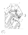
- Fig. 7 is a partial view of the base frame of an embodiment of the vehicle seat according to the invention shown, which is in a transition position, for example, from a sitting position in a table position, wherein the position of the seat part frame 3b according to the Fig. 4 has remained unchanged and only the back frame 2 b is moved or folded in the direction of the seat part frame 3 b.
- the first leaf spring 40 and the portion 40 a of the curved portion of the leaf spring 40 is moved out of the first locking portion 6 a of the first cam 6, whereby the leaf spring 40 is subjected to a compressive force and thus from a first tensioned Position is urged into a second cocked position.
- the leaf spring 40 is transferred from a first substantially aligned in the seat height direction H position, a second likewise cocked position, whereby the leaf spring 40 and preferably in the seat longitudinal direction L upper portion of the leaf spring 40 in the seat longitudinal direction L is bent backwards, whereby the Leaf spring 40 is aligned at an acute angle to the first position.
- the cam track 6c or the cam disc edge 6c is moved past the portion 40a of the leaf spring 40, but the portion 40a preferably always contacts the first cam 6 or the cam disc edge 6c of the first cam disc 6.
- the backrest frame 3b is now in a non-lockable transition position at an angle between 0 ° and 90 ° with respect to the seat part frame 3b.
- the Fig. 8 shows a partial view of the base frame of an embodiment of the vehicle seat according to the invention, which in a table position according to the Fig. 2 is locked, with only the back frame 2b from the in Fig. 7 shown transition position further in the direction of the seat part frame 3b has moved or folded, whereby now the seat part frame 3b and the back frame 2b each extend substantially in the seat longitudinal direction L.
- the first cam 6 was also rotated further counterclockwise C until the portion 40a of the first leaf spring 40 could engage the second detent portion 6b of the first cam 6.
- the leaf spring 40 could thus move from its second cocked position to its first cocked position and thus locks the back frame 2b in a table position.
- the second locking portion 6b of the first cam 6 in seat width direction B faces the first locking portion 7a of the second cam 7, the first locking portion 6a of the first cam 6 and the second locking portion 7b of the second cam 7 each being in the seat height direction H above the common axis ,
- An adjustment of the seat part 3 and the backrest 2 for example, by the use of human muscle power, ie manually possible, but also an electrically controlled system for adjusting the seat part 3 and the backrest 2 can be arranged on the seat 1.
Abstract
Description
Die vorliegende Erfindung bezieht sich auf einen klappbaren Fahrzeugsitz, insbesondere für Nutzfahrzeuge, mit einer Rückenlehne und einem Sitzteil gemäß dem Oberbegriff des Anspruches 1.The present invention relates to a foldable vehicle seat, in particular for commercial vehicles, with a backrest and a seat part according to the preamble of claim 1.
Fahrzeugsitze, insbesondere Fahrzeugsitze mit klappbarer Rückenlehne und stationär angeordnetem Sitzteil sind beispielsweise aus dem Automobilsektor hinreichend bekannt, wobei hierbei beispielsweise die Rückenlehne in eine Liegeposition bewegt werden kann, um dem Passagier die Möglichkeit zu geben sich in einer zurückgelehnten Position zu entspannen oder auch in Richtung des Sitzteiles geklappt werden kann, wodurch beispielsweise in größeren Fahrzeugen, wie in SUVs ein Ablageelement, wie z.B. ein Tisch entsteht.Vehicle seats, especially vehicle seats with foldable backrest and stationary seat part are well known, for example from the automotive sector, in which case, for example, the backrest can be moved to a lying position to give the passenger the opportunity to relax in a reclined position or in the direction of Seat part can be folded, which, for example, in larger vehicles, such as SUVs a storage element, such as a table is created.
Weiterhin sind aus dem Stand der Technik auch Sitze bekannt, welche durch eine Drehkonsole um einen definierten Winkel gedreht werden können, um folglich den unterschiedlichen Ansprüchen der Passagiere an die Sitzrichtung gerecht zu werden.Furthermore, from the prior art, seats are known, which can be rotated by a turntable console by a defined angle, so as to meet the different demands of the passengers to the seating direction.
Wird jedoch zusätzlicher Platz im Fahrzeug benötigt, um beispielsweise zusätzliches Gepäck oder Einkäufe verstauen zu können, so müssen die Sitze erst vollständig aus dem Fahrzeug ausgebaut und beispielsweise in der Wohnung oder dem Keller gelagert werden. Dieser Ausbau ist aufgrund der heute vorherrschenden hohen Sicherheitsanforderungen an einen Fahrzeugsitz auch mit einer gewissen Kraftanstrengung verbunden und verlangt zudem oftmals zudem ein ausgeprägtes technisches Verständnis zur Anordnung und dem Aufbau des Sitzes.However, if additional space is needed in the vehicle to stow, for example, additional luggage or purchases, the seats must first be completely removed from the vehicle and stored for example in the apartment or the basement. This expansion is due to the prevailing high safety requirements for a vehicle seat also associated with a certain effort and also often also requires a strong technical understanding of the arrangement and design of the seat.
Demgegenüber sind die in einem Nutzfahrzeug, wie beispielsweise einem Traktor oder einem Stapler angeordneten Fahrersitze derart mit der Fahrzeugkarosserie bzw. der Fahrzeuginnenwandung verbunden, dass diese von einem Fahrzeugführer nicht aus- und wieder eingebaut werden können, ohne vorher wesentliche Elemente des Fahrzeuges bzw. des Fahrzeuginnenraumes demontieren zu müssen.In contrast, arranged in a commercial vehicle such as a tractor or a stacker driver seats are connected to the vehicle body or the vehicle inner wall so that they can not be removed and reinstalled by a driver, without first essential elements of the vehicle or the vehicle interior to dismantle.
Aufgrund des begrenzten Innenraumes in einem Nutzfahrzeuges ist zudem meist nur ein Fahrersitz in dem Nutzfahrzeug angeordnet, da ein zweiter fest angeordneter Passagiersitz derart viel Platz im Innenraum einnehmen würde, dass der Fahrer entweder nicht mehr an für ihn wichtige Bereiche des Innenraumes gelangt, oder selbst nicht mehr unbehindert bis zum Fahrersitz laufen kann. Dadurch ist es dem Fahrer nicht möglich einen weiteren Passagier mit seinem Nutzfahrzeug zu befördern.Due to the limited interior space in a commercial vehicle usually only a driver's seat is arranged in the commercial vehicle, as a second fixed passenger seat would occupy so much space in the interior, that the driver either no longer gets to him important areas of the interior, or even not can run more unobstructed to the driver's seat. As a result, it is not possible for the driver to carry another passenger with his commercial vehicle.
Da jedoch vorzugsweise im privaten landwirtschaftlichen Betrieb der Traktor auch als Transport und Verkehrsmittel verwendet wird, bedarf es der Lösung zumindest einen weiteren Passagier sitzend im Innenraum, unter Beachtung der vorliegenden gesetzlichen Bestimmungen, zu transportieren, ohne dass der Fahrer dauerhaft durch die Anordnung eines zweiten Sitzes negativ beeinträchtigt wird.However, since the tractor is preferably used as a transport and transport in private agricultural operation, it requires the solution at least one other passenger sitting in the interior, in accordance with the present legal provisions to transport without the driver permanently by the arrangement of a second seat is adversely affected.
Demnach ist es die Aufgabe der vorliegenden Erfindung einen klappbaren Passagiersitz zur Verfügung zu stellen, der es ermöglich platzsparend zusammengeklappt zu werden, wobei die Bedürfnisse des Passagiers an ein komfortables Sitzen und die gesetzlichen Anforderungen an ein sicheres Befördern eines Passagiers berücksichtigt werden.Accordingly, it is the object of the present invention to provide a folding passenger seat, which makes it possible to save space to be folded, taking into account the needs of the passenger to a comfortable sitting and the legal requirements for a safe carrying a passenger.
Diese Aufgabe löst die vorliegende Erfindung mittels eines klappbaren Fahrzeugsitzes gemäß dem Anspruch 1.This object is achieved by the present invention by means of a folding vehicle seat according to claim 1.
Beansprucht wird demnach ein klappbarer Fahrzeugsitz, insbesondere für Nutzfahrzeuge, mit einer Rückenlehne und einem Sitzteil, wobei die Rückenlehne klappbar ausgebildet und zumindest mit einem ersten Kurvenelement verbunden ist und das Sitzteil klappbar ausgebildet und zumindest mit einem zweiten Kurvenelement verbunden ist, wobei beide Kurvenelemente in Sitzbreitenrichtung beabstandet voneinander und um eine sich in Sitzbreitenrichtung erstreckende gemeinsame Achse drehbar angeordnet sind, damit die Rückenlehne und das Sitzteil um mindestens 90° drehbar sind.Claimed is therefore a folding vehicle seat, in particular for commercial vehicles, with a backrest and a seat part, wherein the backrest is foldable and at least connected to a first curve element and the seat part foldable formed and at least connected to a second curve element, wherein both curve elements in seat width direction spaced from each other and are rotatably disposed about a common axis extending in the seat width direction, so that the backrest and the seat part are rotatable by at least 90 °.
Folglich weist der Fahrzeugsitz nicht nur eine klappbare bzw. schwenkbare Rückenlehne auf, sondern ebenfalls ein klappbares bzw. schwenkbares Sitzteil, wobei der Fahrzeugsitz bzw. Sitz demnach in mindestens drei unterschiedlichen Verwendungspositionen arretierbar ist.Consequently, the vehicle seat not only has a foldable or pivotable backrest, but also a foldable or pivotable seat part, the vehicle seat or seat accordingly being lockable in at least three different use positions.
Nämlich in einer ersten platzsparenden Position, wobei die Rückenlehne und ebenso das Sitzteil im Wesentlichen orthogonal bzw. senkrecht bzw. vertikal zu einer Oberfläche des Fahrzeugbodens ausgerichtet sind, d.h., dass das Sitzteil in Richtung der Rückenlehne hochgeklappt ist. Des Weiteren ist der erfindungsgemäße Sitz in einer Sitzposition arretierbar, d.h., das die Rückenlehne im Wesentlichen orthogonal zu der Fahrzeugbodenoberfläche ausgerichtet ist, wobei die Sitzfläche im Wesentlichen parallel zu der Fahrzeugbodenoberfläche ausgerichtet ist, wodurch das Sitzteil und die Rückenlehne folglich in einen Winkel von mindestens 90° aufspannen, so dass ein Passagier bzw. eine Person auf dem erfindungsgemäßen Fahrzeugsitz sitzen kann. Die dritte Position, in welcher der erfindungsgemäße Sitz arretierbar ist, ist die Ablage- bzw. Tischposition, wobei die Rückenlehne und das Sitzteil im Wesentlichen parallel zu der Fahrzeugbodenoberfläche ausgerichtet sind, d.h., dass die Rückenlehne in Richtung des aufgeklappten Sitzteiles geklappt ist. Folglich bietet der erfindungsgemäße Sitz die Möglichkeit auf der Rückenlehnenrückseite diverse Gegenstände ablegen zu können.Namely, in a first space-saving position, wherein the backrest and also the seat part are aligned substantially orthogonal to a surface of the vehicle floor, that is, that the seat part is folded up in the direction of the backrest. Furthermore, the seat according to the invention can be locked in a sitting position, ie, the backrest is oriented essentially orthogonal to the vehicle floor surface, the seat surface being oriented substantially parallel to the vehicle floor surface, whereby the seat part and the backrest are thus at an angle of at least 90 ° span, so that a passenger or a person can sit on the vehicle seat according to the invention. The third position in which the seat according to the invention can be locked is the shelf position, wherein the backrest and the seat part are aligned substantially parallel to the vehicle floor surface, that is, the backrest is folded in the direction of the unfolded seat part. Consequently, the seat according to the invention offers the possibility to be able to deposit various objects on the backrest back.
Die Fahrzeugbodenoberfläche ist dabei eine sich im Wesentlichen parallel zur Fahrbahn erstreckende Ebene, wobei diese Ebene im Wesentlichen horizontal ausgerichtet ist, wenn sich das Fahrzeug auf einer ebenen Fahrbahn, ohne Neigungen bzw. Steigungen bzw. Gefälle befindet.In this case, the vehicle floor surface is a plane extending essentially parallel to the roadway, this plane being oriented essentially horizontally when the vehicle is on a flat roadway, without inclines or inclines or inclines.
Der Klappmechanismus des Sitzteiles sowie der Rückenlehne des erfindungsgemäßen Sitzes wird durch mindestens zwei Kurvenelemente sowie daran angeordnete Blattfedern ermöglicht, wobei die Kurvenelemente jeweils eine Kurvenbahn bzw. einen Kurvenelementrand aufweisen, welche bzw. welcher im Wesentlichen ungleichförmig gebildet ist. D.h., dass der Kurvenelementrand nicht zentrisch um den Mittelpunkt bzw. die Drehachse des Kurvenelementes verläuft. Die Kurvenelemente sind demnach aus dem Stand der Technik bekannte Elemente und sollen folglich hier nicht weiter beschrieben werden.The folding mechanism of the seat part and the backrest of the seat according to the invention is made possible by at least two cam elements and leaf springs arranged thereon, the cam elements each having a cam track or a cam element edge which is formed substantially non-uniformly. This means that the cam element edge does not run centrically around the center or the axis of rotation of the cam element. The curve elements are therefore known from the prior art elements and will therefore not be further described here.
Die Rückenlehne sowie das Sitzteil des erfindungsgemäßen Sitzes sind vorzugsweise jeweils mit einem eigenen Kurvenelement verbunden, welche bevorzugt auf einer sich im Wesentlichen in Sitzbreitenrichtung erstreckenden gemeinsamen Achse gelagert sind bzw. sich um diese Achse drehen.The backrest and the seat part of the seat according to the invention are preferably each connected to a separate curve element, which preferably on one substantially are mounted in the seat width direction extending common axis or rotate about this axis.
Die Kurvenelemente sind dabei zumindest abschnittsweise voneinander beabstandet angeordnet, so dass die Kurvenelemente die Möglichkeit aufweisen unabhängig voneinander um die Achse gedreht werden zu können.The curve elements are at least partially spaced from each other, so that the curve elements have the ability to be rotated independently of each other about the axis can.
In einem bevorzugten Ausführungsbeispiel weist das erste und das zweite Kurvenelement jeweils mindestens zwei Arretierungsbereiche auf. Diese Arretierungsbereiche sind vorzugsweise in einem Winkel von ca. 90°, weiterhin bevorzugt in einem Winkel von 90° bis 110° voneinander beabstandet auf der Kurvenbahn des Kurvenelementes zueinander angeordnet.In a preferred embodiment, the first and the second cam element each have at least two locking areas. These locking areas are preferably arranged at an angle of about 90 °, further preferably at an angle of 90 ° to 110 ° apart from each other on the curved path of the cam element to each other.
Die mindestens zwei Kurvenelemente können jeweils eine zueinander unterschiedliche Gestalt aufweisen, wobei jedoch die Kurvenbahnen bzw. die Kurvenelementränder zwischen den beiden Arretierungsbereichen im Wesentlichen identisch ausgeführt sind.The at least two curve elements may each have a mutually different shape, but the cam tracks or the curve element edges between the two Arretierungsbereichen are made substantially identical.
Vorzugsweise sind die Arretierungsbereiche als Ausnehmungen zum Eingreifen eines Abschnittes eines zumindest teilweise gekrümmt ausgebildeten Bereiches von jeweils mindestens einer Blattfeder ausgebildet.Preferably, the locking portions are formed as recesses for engaging a portion of an at least partially curved portion formed by at least one leaf spring.
D.h., dass in diese Arretierungsbereiche bzw. Ausnehmungen bzw. Dellen lediglich ein definierter Bereich von an den Kurvenelementen angeordneten Blattfedern eingereift, wobei dementsprechend mindestens zwei Blattfedern in dem erfindungsgemäßen Sitz angeordnet sind.In other words, only a defined range of leaf springs arranged on the cam elements is entangled in these locking areas or recesses or dents, and accordingly at least two leaf springs are arranged in the seat according to the invention.
Die Blattfedern weisen einen an den Kurvenelementen angeordneten Bereich auf, welcher gegenüber der im Wesentlichen geradlinig ausgebildeten Blattfeder derart gekrümmt ist, dass eine Berührung des Kurvenelementes bzw. des Kurvenelementrandes mit der Blattfeder nur über diesen gekrümmten bzw. gebogenen bzw. deformierten Bereich der Blattfeder erfolgt.The leaf springs have a arranged on the cam elements area which is curved relative to the substantially rectilinear leaf spring such that a contact of the cam element or the cam element edge with the leaf spring takes place only on this curved or bent or deformed region of the leaf spring.
Bevorzugt liegt somit an jedem Kurvenelement außenseitig jeweils die mindestens eine Blattfeder an, welche mit dem Kurvenelement wechselwirkt, indem zumindest der Abschnitt der Blattfeder in die Arretierungsbereiche eingreift.Thus, each of the curve elements preferably has on its outside the at least one leaf spring, which interacts with the curve element, in that at least the section of the leaf spring engages in the locking regions.
D.h., dass bei einer Drehung des Kurvenelementes um die gemeinsame Achse die Blattfeder bzw. der in den Arretierungsbereich des Kurvenelementes eingreifende Abschnitt der Blattfeder aus dem einen Arretierungsbereich herausbewegt wird, über den Kurvenelementrand des Kurvenelementes bis zum dem anderen Arretierungsbereich geführt wird und dann in den zweiten Arretierungsbereich eingreift.That is, upon rotation of the cam member about the common axis, the leaf spring or the engaging in the locking portion of the cam member portion of the leaf spring is moved out of the one Arretierungsbereich is guided over the cam element edge of the cam member to the other Arretierungsbereich and then into the second Locking area engages.
Folglich ist vorzugsweise zumindest der gekrümmt ausgebildete Bereich der Blattfedern im Wesentlichen dauerhaft mit den jeweiligen Kurvenelementen in Berührung.Consequently, preferably at least the curved portion of the leaf springs is substantially permanently in contact with the respective cam elements.
In einem weiteren bevorzugten Ausführungsbeispiel sind die Kurvenelemente als Kurvenscheiben ausgebildet, welche zumindest abschnittsweise jeweils einen Kurvenscheibenrand aufweisen, an dem die Ausnehmungen angeordnet sind.In a further preferred embodiment, the cam elements are designed as cam disks which, at least in sections, each have a cam disk edge on which the recesses are arranged.
Entsprechend der oben aufgeführten Kurvenelemente, welche beispielsweise als Kurvenrollen bzw. Kurvenzylinder ausgeführt sein können, weist die Kurvenscheibe ebenfalls mindestens zwei Arretierungsbereiche bzw. Ausnehmungen bzw. Dellen auf, welche auf der Kurvenbahn, nämlich dem Kurvenscheibenrand vorzugsweise in einem Winkel von ca. 90°, weiterhin bevorzugt in einem Winkel von 90°bis 110° voneinander beabstandet sind.Corresponding to the curve elements listed above, which may be designed, for example, as cam rollers or cam cylinder, the cam also has at least two Arretierungsbereiche or recesses or dents on the curved path, namely the cam plate edge preferably at an angle of about 90 °, further preferably at an angle of 90 ° to 110 ° apart.
Es ist jedoch auch denkbar, dass die Kurvenelemente bzw. die Kurvenscheiben jeweils mehr als zwei Arretierungsbereiche aufweisen, wobei der dritte oder der vierte Arretierungsbereich vorzugsweise nicht zwischen dem ersten und zweiten Arretierungsbereich angeordnet ist, sondern vor dem ersten und/oder nach dem zweiten Arretierungsbereich, um das Sitzteil, bzw. die Rückenlehne in unterschiedlichste Positionen zueinander arretieren zu können.However, it is also conceivable that the cam elements or the cam disks each have more than two locking areas, wherein the third or the fourth locking area is preferably not arranged between the first and second locking areas, but before the first and / or after the second locking area, to lock the seat part, or the backrest in different positions to each other.
Folglich kann die Rückenlehne nicht nur nach vorn, sondern auch nach hinten geklappte werden, bzw. in verschiedene nach hinten geklappten Positionen arretiert werden. Oder das Sitzteil kann eine zur Fahrzeugbodenoberfläche geneigte Position einnehmen, so dass beispielsweise der in Fahrtrichtung vordere Bereich des Sitzteils in Richtung der Fahrzeugbodenoberfläche geneigt ist.Consequently, the backrest can be folded not only forward, but also to the rear, or be locked in various folded back positions. Or the seat part can assume a position inclined to the vehicle floor surface, so that, for example, the front area of the seat part in the direction of travel is inclined in the direction of the vehicle floor surface.
Weiterhin ist es möglich, dass die beiden Kurvenelemente eine zueinander unterschiedliche Anzahl von Arretierungsbereichen aufweisen, so dass beispielsweise das Kurvenelement, welches mit dem Sitzteil verbunden ist lediglich zwei Arretierungsbereiche aufweist, wobei das Kurvenelement, welches mit der Rückenlehne verbunden ist beispielsweise drei oder mehr Arretierungsbereiche aufweist.Furthermore, it is possible that the two cam elements have a mutually different number of locking areas, so that, for example, the cam member which is connected to the seat part has only two locking portions, wherein the curved element, which is connected to the backrest, for example, has three or more locking areas.
Vorzugsweise erstrecken sich die Arretierungsbereiche in radialer Richtung von der Oberfläche des Kurvenscheibenrandes der Kurvenscheibe nach innen sowie über die gesamte Breite des Kurvenscheibenrandes und über einen definierten Bereich entlang des Kurvenscheibenrandes.The locking regions preferably extend in the radial direction from the surface of the cam disk edge of the cam disk inwards and over the entire width of the cam disk rim and over a defined region along the cam disk rim.
Demnach bilden die Arretierungsbereiche bzw. die Ausnehmungen eine Abweichung von der Kurvenbahn des Kurvenelementes, welche sich von der Kurvenbahn radial nach innen der Kurvenscheibe erstreckt und vorzugsweise im Wesentlichen die Form des gekrümmt ausgebildeten Abschnittes der Blattfeder aufweist, welcher in die Ausnehmungen der Kurvenscheibe bzw. des Kurvenelementes eingreift.Accordingly, the locking areas or the recesses form a deviation from the curved path of the cam element, which extends from the cam track radially inwardly of the cam plate and preferably has substantially the shape of the curved portion of the leaf spring, which in the recesses of the cam or the Curve element engages.
Vorzugsweise sind die mindestens zwei Arretierungsbereiche bzw. Ausnehmungen der mindestens zwei Kurvenscheiben derart angeordnet, dass die erste Ausnehmung der ersten Kurvenscheibe nicht in jeder Positionierung des Sitzteiles und der Rückenlehne der ersten Ausnehmung der zweiten Kurvenscheibe in Sitzbreitenrichtung gegenüberliegt.The at least two locking regions or recesses of the at least two cams are preferably arranged such that the first recess of the first camming disk does not oppose in the seat width direction in every positioning of the seat part and the backrest of the first recess of the second camming disk.
Vielmehr liegt der erste Arretierungsbereich des ersten Kurvenelementes dem ersten Arretierungsbereich des zweiten Kurvenelementes in Sitzbreitenrichtung im Wesentlichen gegenüberliegt, wenn eine Sitzfläche des Sitzelementes sich im Wesentlichen parallel und eine Anlehnfläche der Rückenlehne sich im Wesentlichen orthogonal zu einer Fahrzeugbodenoberfläche erstrecken.Rather, the first locking portion of the first cam element is substantially opposite the first locking portion of the second cam member in the seat width direction when a seat surface of the seat member extends substantially parallel and a leaning surface of the seat back substantially orthogonal to a vehicle floor surface.
D.h., dass sich in hierbei der Sitz in einer Sitzposition befindet, in welcher eine Person auf dem Sitz sitzen kann, da zum einen die Rückenlehne nach hinten bzw. oben und das Sitzteil nach unten geklappt ist, wodurch beide Elemente, d.h. das Sitzteil und die Rückenlehne jeweils in einem aufgeklappten Zustand vorliegen.That is to say that in this case the seat is in a sitting position in which a person can sit on the seat, since on the one hand the backrest is folded upwards and the seat part is folded down, whereby both elements, i. the seat part and the backrest are each in an unfolded state.
Weiterhin liegt beispielsweise der zweite Arretierungsbereich des zweiten Kurvenelementes vorzugsweise dem ersten Arretierungsbereich des ersten Kurvenelementes in Sitzbreitenrichtung im Wesentlichen gegenüber, wenn eine Sitzfläche des Sitzelementes sowie eine Anlehnfläche der Rückenlehne sich jeweils im Wesentlichen orthogonal zu einer Fahrzeugbodenoberfläche erstrecken.Further, for example, the second detent portion of the second cam member is preferably substantially opposite to the first detent portion of the first cam member in the seat width direction when a seat surface of the seat member and a leaning surface of the seat back respectively extend substantially orthogonal to a vehicle floor surface.
In dieser platzsparenden Position des erfindungsgemäßen Sitzes ist die Rückenlehne nach hinten bzw. oben geklappt und liegt folglich in einem aufgeklappten Zustand vor, wobei das Sitzteil in Richtung der Rückenlehne nach oben geklappt ist und demnach in einem zugeklappten Zustand vorliegt. In solch einer Position nutzt der Sitz nur einen geringen Bereich des dem erfindungsgemäßen Sitz zur Verfügung stehenden Fahrzeuginnenraumes.In this space-saving position of the seat according to the invention, the backrest is folded backwards or upwards and is therefore in an unfolded state, wherein the seat part is folded in the direction of the backrest upwards and is therefore present in a closed state. In such a position, the seat uses only a small portion of the vehicle interior according to the invention available vehicle interior.
Der zweite Arretierungsbereich des ersten Kurvenelementes liegt vorzugsweise dem ersten Arretierungsbereich des zweiten Kurvenelementes in Sitzbreitenrichtung im Wesentlichen gegenüber, wenn eine Sitzfläche des Sitzelementes sowie eine Anlehnfläche der Rückenlehne sich jeweils im Wesentlichen parallel zu einer Fahrzeugbodenoberfläche erstrecken.The second locking portion of the first cam element is preferably substantially opposite the first locking portion of the second cam member in the seat width direction, when a seat surface of the seat member and a leaning surface of the seat back respectively extend substantially parallel to a vehicle floor surface.
In dieser Anordnung von Sitzteil zu Rückenlehne nimmt der Sitz eine Tisch- bzw. Ablagenposition ein, da die Rückenlehne in Richtung des sich im aufgeklappten Zustand befindlichen Sitzteiles geklappt wird, so dass die Rückenlehnenanlehnfläche der Rückenlehne der Sitzfläche des Sitzteils gegenüberliegt, wobei die Rückenlehnenrückseite der Rückenlehne einen Tisch bzw. eine Ablage bildet, welche sich im Wesentlichen horizontal bzw. parallel zu der Fahrzeugbodenoberfläche erstreckt.In this arrangement of seat part to backrest, the seat assumes a table or shelf position, since the backrest is folded in the direction of the seat part in the unfolded state, so that the Rückenlehnenanlehnfläche the backrest of the seat surface of the seat part opposite, wherein the backrest back of the backrest forms a table or a shelf which extends substantially horizontally or parallel to the vehicle floor surface.
Die Rückenlehenrückseite weist beispielsweise eine Ablagefläche mit einer schalenartige Ausformung und/oder Aussparungen in Form eines Bechers etc auf, welche vorzugsweise aus Kunststoff oder einem anderen schmutzresistenten Material gefertigt ist. Die Ablagefläche, welches an der Rückenlehenrückseite fixiert bzw. angeordnet ist, ermöglicht es folglich diverse Gegenstände verrutschsicher darauf abzulegen.The backrest back, for example, has a storage surface with a shell-like shape and / or recesses in the form of a cup, etc, which is preferably made of plastic or other dirt-resistant material. The storage surface which is fixed or arranged on the Rückenlehenrückseite therefore makes it possible to store various objects slip-proof.
Weiterhin ist die Rückenlehne in einem bevorzugten Ausführungsbeispiel mit der an dem ersten Kurvenelement angeordneten Seite gegenüberliegenden Seite mit einem ersten Tragarm drehbar um die gemeinsame Achse angeordnet.Furthermore, the backrest is arranged in a preferred embodiment with the arranged on the first cam element side opposite side with a first support arm rotatable about the common axis.
Demnach ist die Rückenlehne nicht nur über das Kurvenelement an der gemeinsamen Achse gelagert, sondern gleichzeitig über einen Tragarm, der ebenfalls drehbar um die gemeinsame Achse an dieser Achse gelagert ist. Demnach kann eine Kraftverteilung bzw. -ableitung einerseits über das Kurvenelement und andererseits über den Tragarm erfolgen.Accordingly, the backrest is mounted not only on the cam member on the common axis, but at the same time via a support arm which is also rotatably mounted about the common axis on this axis. Accordingly, a force distribution or derivation on the one hand on the curve element and on the other hand on the support arm done.
Auch das Sitzteil ist vorzugsweise mit der an der zweiten Kurvenscheibe angeordneten Seite gegenüberliegenden Seite mit einem zweiten Tragarm drehbar um die gemeinsame Achse angeordnet.Also, the seat part is preferably arranged with the arranged on the second cam side opposite side with a second support arm rotatable about the common axis.
Folglich ist auch das Sitzteil nicht nur über das Kurvenelement an der gemeinsamen Achse gelagert, sondern auch über einen Tragarm, welcher an der gemeinsamen Achse drehbar gelagert ist.Consequently, the seat part is mounted not only on the cam member on the common axis, but also via a support arm which is rotatably mounted on the common axis.
Eine Überlastung der beiden Kurvenelemente wird demnach vermieden und eine einfache Bewegung bzw. ein einfaches Klappen der Rückenlehen und des Sitzteiles ermöglicht.An overload of the two cam elements is thus avoided and allows easy movement or a simple flaps of the Rückenlehen and the seat part.
Dabei sind die mindestens zwei Tragarme und die mindestens zwei Kurvenelemente derart voneinander beabstandet und drehbar an der gemeinsamen Achse angeordnet, dass sie einander nicht blockieren bzw. in ihrer Bewegung behindern, was vorzugsweise dadurch erreicht wird, dass beispielsweise der Tragarm und das Kurvenelement der Rückenlehne in Sitzbreitenrichtung innerhalb bzw. zwischen dem Tragarm und dem Kurvenelement des Sitzteiles angeordnet sind.In this case, the at least two support arms and the at least two cam elements are spaced from each other and arranged rotatably on the common axis that they do not block each other or hinder their movement, which is preferably achieved in that, for example, the support arm and the cam element of the backrest in Seat width direction are arranged within or between the support arm and the cam element of the seat part.
Es ist jedoch auch denkbar, dass z.B. der Tragarm und das Kurvenelement des Sitzteiles in Sitzbreitenrichtung innerhalb bzw. zwischen dem Tragarm und dem Kurvenelement der Rückenlehne angeordnet sind.However, it is also conceivable that e.g. the support arm and the cam element of the seat part are arranged in the seat width direction within or between the support arm and the cam element of the backrest.
Die Blattfedern, welche mit dem gekrümmt ausgebildeten Abschnitt in die Arretierungsbereiche eingreifen, sind vorzugsweise jeweils mit einem Endbereich zumindest abschnittsweise verdrehsteif in jeweils einer zum Austausch der Blattfedern lösbaren Klemmvorrichtung angeordnet.The leaf springs, which engage with the curved portion formed in the Arretierungsbereiche are preferably each arranged with an end portion at least partially torsionally rigid in each case one for replacing the leaf springs releasable clamping device.
Demzufolge ist es möglich die Blattfedern schnell und einfach austauschen zu können, wenn beispielsweise eine Beschädigung der Blattfedern vorliegt.Consequently, it is possible to replace the leaf springs quickly and easily, for example, if there is damage to the leaf springs.
Weiterhin ist es möglich, dass der Fahrzeugsitz einen Becherhalter bzw. Flaschenhalter aufweist, welcher nicht auf der Rückenlehnenrückseite der Rückenlehne angeordnet ist, sondern in einem in Sitzlängsrichtung hinteren Bereich des Sitzes, vorzugsweise zwischen einer Haltevorrichtung zum Anbringen des Sitzes in einem Bereich des Fahrzeuges und dem Sitzteil bzw. der Rückenlehne. Dieser Becherhalter kann folglich dann verwendet werden, wenn die Rückenlehne in Richtung des Sitzteiles zugeklappt ist, d.h., wenn die Rückenlehne bzw. die Anlehnfläche der Rückenlehne und das Sitzteil bzw. die Sitzfläche des Sitzteils sich im Wesentlichen parallel zu der Fahrzeugbodenoberfläche befinden und der Sitz demnach in einer Tischposition arretiert ist.Furthermore, it is possible that the vehicle seat has a cup holder or bottle holder, which is not arranged on the backrest back of the backrest, but in a rear seat longitudinal direction of the seat, preferably between a holding device for attaching the seat in an area of the vehicle and the Seat part or the backrest. This cup holder can consequently be used when the backrest is folded in the direction of the seat part, ie, when the backrest or the leaning surface of the backrest and the seat part or the seat surface of the seat part are substantially parallel to the vehicle floor surface and the seat is thus locked in a table position.
Zudem ist es möglich, dass der Sitz ein Gurtsystem mit einem Gurtstraffer bzw. einer Gurtaufrollvorrichtung, einem Gurtschloss, einem Gurtband sowie einer Steckzunge bzw. Gurtzunge aufweist. Dieses Gurtsystem ist direkt an dem Fahrzeugsitz angeordnet und kann gemeinsam mit dem gesamten Sitz montiert bzw. demontier werden, so dass keine zusätzliche Montage eines gesonderten Gurtsystems innerhalb des Fahrzeuges notwendig ist.In addition, it is possible that the seat has a belt system with a belt tensioner or a belt retractor, a buckle, a belt and a tongue or tongue tongue. This belt system is arranged directly on the vehicle seat and can be assembled or disassembled together with the entire seat, so that no additional installation of a separate belt system within the vehicle is necessary.
Folglich kann der erfindungsgemäße Sitz als Zweitsitz in ein Fahrzeug bzw. ein Nutzfahrzeug integriert bzw. montiert werden oder auch als Fahrzeugsitz dienen, welcher beispielsweise im Tausch zu dem bisherigen Fahrzeugsitz in dem Fahrzeug angeordnet wird.Consequently, the seat according to the invention can be integrated or mounted as a second seat in a vehicle or a commercial vehicle or serve as a vehicle seat, which is arranged for example in exchange for the previous vehicle seat in the vehicle.
Weitere Vorteile, Ziele und Eigenschaften der vorliegenden Erfindung werden anhand nachfolgender Beschreibung anliegender Zeichnung erläutert, in welcher beispielhaft eine Ausführungsform des erfindungsgemäßen Sitzes sowie Ansichten zu unterschiedlichen Positionierungen der Kurvenelemente einer Ausführungsform des erfindungsgemäßen Sitzes dargestellt wird.Further advantages, objects and features of the present invention will be explained with reference to the following attached drawing in which an embodiment of the seat according to the invention and views are shown for different positions of the cam elements of an embodiment of the seat according to the invention.
Komponenten, welche in den Figuren wenigstens im Wesentlichen hinsichtlich ihrer Funktion übereinstimmen, können hierbei mit gleichen Bezugszeichen gekennzeichnet sein, wobei diese Komponenten nicht in allen Figuren gekennzeichnet und erläutert sein müssen.Components which at least substantially coincide in the figures with respect to their function may in this case be identified by the same reference symbols, these components not having to be identified and explained in all figures.
In den Figuren zeigen:
- Fig. 1
- eine Prinzipskizze einer Ausführungsform des erfindungsgemäßen Fahrzeugsitzes, welcher in einer Sitzposition arretiert ist;
- Fig. 2
- eine Prinzipskizze einer Ausführungsform des erfindungsgemäßen Fahrzeugsitzes, welcher in einer Tisch- bzw. Ablageposition arretiert ist;
- Fig. 3
- eine Prinzipskizze einer Ausführungsform des erfindungsgemäßen Fahrzeugsitzes, welcher in einer Platzsparposition arretiert ist;
- Fig. 4
- eine Teilansicht des Grundgestelles einer Ausführungsform des erfindungsgemäßen Fahrzeugsitzes, welcher in einer Sitzposition arretiert ist;
- Fig. 5
- eine Teilansicht des Grundgestelles einer Ausführungsform des erfindungsgemäßen Fahrzeugsitzes, welcher sich in einer Übergangsposition beispielsweise von einer Sitzposition in eine Platzsparposition befindet;
- Fig. 6
- eine Teilansicht des Grundgestelles einer Ausführungsform des erfindungsgemäßen Fahrzeugsitzes, welcher in einer Platzsparposition arretiert ist;
- Fig. 7
- eine Teilansicht des Grundgestelles einer Ausführungsform des erfindungsgemäßen Fahrzeugsitzes, welcher sich in einer Übergangsposition beispielsweise von einer Sitzposition in eine Tischposition befindet; und
- Fig. 8
- eine Teilansicht des Grundgestelles einer Ausführungsform des erfindungsgemäßen Fahrzeugsitzes, welcher in einer Tischposition arretiert ist.
- Fig. 1
- a schematic diagram of an embodiment of the vehicle seat according to the invention, which is locked in a sitting position;
- Fig. 2
- a schematic diagram of an embodiment of the vehicle seat according to the invention, which is locked in a table or storage position;
- Fig. 3
- a schematic diagram of an embodiment of the vehicle seat according to the invention, which is locked in a space-saving position;
- Fig. 4
- a partial view of the base frame of an embodiment of the vehicle seat according to the invention, which is locked in a sitting position;
- Fig. 5
- a partial view of the base frame of an embodiment of the vehicle seat according to the invention, which is in a transition position, for example, from a sitting position to a space saving position;
- Fig. 6
- a partial view of the base frame of an embodiment of the vehicle seat according to the invention, which is locked in a space-saving position;
- Fig. 7
- a partial view of the base frame of an embodiment of the vehicle seat according to the invention, which is located in a transition position, for example, from a sitting position to a table position; and
- Fig. 8
- a partial view of the base frame of an embodiment of the vehicle seat according to the invention, which is locked in a table position.
Die Anlehnfläche 2a und die Sitzfläche 3a sind vorzugsweise jeweils zumindest teilweise gepolstert und liegen auf einem Rückenlehnenrahmen 2b bzw. einem Sitzteilrahmen 3b auf bzw. sind an diesen Rahmen verrutschfest angeordnet.The leaning
Der Rückenlehnenrahmen 2b ist mit einer ersten Kurvenscheibe 6 und einem ersten Tragarm 8 an einer gemeinsamen Achse 5, welche sich in Sitzbreitenrichtung B erstreckt drehbar angeordnet, wobei der Sitzteilrahmen 3b mit einer zweiten Kurvenscheibe 7 und einem zweiten Tragarm 9 ebenfalls an der gemeinsamen Achse 5 drehbar angeordnet sind.The seat back
Die gemeinsame Achse 5 wird mittels zweier seitlicher Befestigungselemente 10, welche im Wesentlichen in Sitzbreitenrichtung beidseitig der gemeinsamen Achse 5 angeordnet sind und sich zumindest abschnittsweise in Sitzlängsrichtung L erstrecken, verdrehsteif gelagert. Diese Befestigungselemente 10 sind an Halteelementen 11 angeordnet, welche sich im Wesentlichen in Sitzbreitenrichtung B nach außen erstrecken und in Sitzlängsrichtung L am hinteren Ende der Befestigungselemente 10 angeordnet sind.The
Folglich ist es möglich, dass die Halteelemente 11 und die Befestigungselemente 10 aus einem einzigen Element bestehen, bei welchem durch Biegung eines definierten Bereiches die einzelnen Abschnitte des Halteelementes 11 und des Befestigungselementes 10 erzeugt werden.Consequently, it is possible for the holding
Andererseits können beide Elemente 10, 11 auch einzelne bzw. eigenständige Elemente 10, 11 sein, welche in einem Fügebereich miteinander verbunden, beispielsweise verschweißt werden.On the other hand, both
Die Halteelemente 11 weisen jeweils eine Durchgangsöffnung 11 a bzw. eine Bohrung 11a auf, durch welche Schrauben oder ähnliches geführt werden können, um die Halteelemente 11 und damit den gesamten Sitz 1 an einem Bereich im Innenraum des Fahrzeuges anbringen zu können.The holding
Die erste Kurvenscheibe 6 und der erste Tragarm 8 sind auf der gemeinsamen Achse 5 zwischen dem zweiten Tragarm 9 und der zweiten Kurvenscheibe 7 angeordnet und werden demnach von dem zweiten Tragarm 9 und der zweiten Kurvenscheibe 7 eingeschlossen.The
Es ist jedoch auch denkbar, dass die erste Kurvenscheibe 6 und der erste Tragarm 8 die zweite Kurvenscheibe 7 und den zweiten Tragarm 9 in Sitzbreitenrichtung B einschließen bzw. begrenzen.However, it is also conceivable that the
Weiterhin ist gemäß
Dabei ist das Gutschloss 4c in Sitzbreitenrichtung B an der einen Seite des Sitzes 1 und der Gurtaufroller 4a, die Steckzunge 4b sowie das an der Steckzunge befestigte Band 4d, welches durch den Gurtaufroller 4a aufgerollt und fest gespannt wird, in Sitzbreitenrichtung B an der anderen Seite des Sitzes 1 angeordnet.Here, the lock is 4c in the seat width direction B on one side of the seat 1 and the
Die vorzugsweise gepolsterte Sitzfläche 3a und Anlehnfläche 2a weisen zudem sich über die Sitzfläche 3a bzw. die Anlehnfläche 2a erstreckende Rillen 12 bzw. Vertiefungen 12 im Polster 2a, 3a auf, um beispielsweise eine Luftzirkulation zwischen dem auf dem Sitz sitzenden Passagier (hier nicht gezeigt) und dem Sitz 1 zu ermöglichen, so dass der Passagier auch bei sehr warmen Umgebungstemperaturen im Kontaktbereich 2a, 3a mit dem Sitz 1 nicht schwitzt.The preferably upholstered
Die Rillen erstrecken sich gemäß der
In bzw. auf der Sitzfläche 3a erstrecken sich die Rillen 12 in Sitzlängsrichtung L von einem hinteren Bereich der Sitzfläche 2a in Richtung eines vorderen Bereiches, um dort in einen nach außen gebogenen Bereich überzugehen.In or on the
In dieser dargestellten Ausführungsform weisen die Sitzfläche 3a und die Anlehnfläche 2a jeweils zwei Rillen 12 auf, wobei jedoch auch mehr als zwei Rillen 12 angeordnet sein können. Auch die Form der Rillen 12 und deren Anordnung zueinander sind nicht auf dieses Ausführungsbeispiel begrenzt.In this illustrated embodiment, the
Die
Folglich erstrecken sich die Rückenlehne 2 bzw. die Anlehnfläche 2a der Rückenlehne sowie das Sitzteil 3 bzw. die Sitzfläche 3a des Sitzteils 3 parallel zu der Fahrzeugbodenoberfläche (hier nicht gezeigt) bzw. in Sitzlängsrichtung L, wodurch ein Tischelement 13, welches auf der Rückseite des Rückenlehne 2, vorzugsweise am Rückenlehnenrahmen 2b angeordnet ist, im Wesentlichen parallel zur Fahrzeugbodenoberfläche ausgerichtet wird.Consequently, the
Dieses Tischelement 13 weist eine umlaufende Kante 13a bzw. Erhebung 13a auf, durch welche beispielsweise ein Herunterrutschen eines auf dem Tischelement 13 abgelegten Gegenstandes, z.B. während der Fahrt des Fahrzeuges vermieden werden kann.This
Das Tischelement 13 bzw. die umlaufende Kante 13a sind vorzugsweise aus Kunststoff, wie beispielsweise Polyethylen, Polypropylen, Polyvinylchlorid, Materialgemischen oder anderenThe
Materialen, welche vorzugsweise schmutzabweisend und lebensdauerbeständig sind, hergestellt.Materials which are preferably dirt-repellent and life-resistant, made.
Zudem zeigt
Der durch den Halter 20 gehaltene Becher ist folglich zwischen den seitlichen Befestigungselementen 10 sowie zwischen einer Fahrzeugwandung (hier nicht gezeigt), an welcher die Haltelemente 11 angeordnet werden, und dem Sitz 1 mit der Rückenlehne 2 und dem Sitzteil 3 angeordnet und somit derart vor Erschütterungen, beispielsweise in unwegsamen Gelände geschützt, dass ein Umkippen des Bechers bzw. der Flache während der Fahrt bzw. dem Betrieb des Fahrzeuges vermieden werden.The cup held by the
In der
Der Sitzteilrahmen 3b des Sitzteiles 3 ist auf einem Tragelement 30 bzw. einer Tragplatte 30 mittels Schrauben 31 fixiert, wobei das L-förmige Tragelement 30 sich in der Ansicht gemäß
Der sich in Sitzlängsrichtung L nach hinten erstreckende Bereich des Tragelementes 30 weist folglich zwei sich erstreckende Tragarme (hier nicht gezeigt) auf, wobei der eine Tragarm in der zweiten Kurvenscheibe (hier nicht gezeigt) und der andere Tragarm in dem zweiten Tragarm (hier nicht gezeigt) des Sitzteiles 3 mündet.The rearwardly extending in the seat longitudinal direction L region of the
Folglich ist das Sitzteil 3 über das Tragelement 30 mit der zweiten Kurvenscheibe und dem zweiten Tragarm, welche jeweils drehbar um die gemeinsame Achse (hier nicht gezeigt) gelagert sind, verbunden.Consequently, the
Es ist folglich auch denkbar, dass ein weiteres Tragelement (hier nicht gezeigt) an der Rückseite der Rückenlehne 2 zwischen dem Rückenlehnenrahmen 2b und dem Tischelement (hier nicht gezeigt) angeordnet ist, welches mit der ersten Kurvenscheibe (hier nicht gezeigt) und dem ersten Tragarm (hier nicht gezeigt), welche verdrehbar auf der gemeinsamen Achse gelagert sind, verbunden ist.It is therefore also conceivable that a further support element (not shown here) is arranged on the back of the
Der Rückenlehnenrahmen 2b sowie der Sitzteilrahmen 3b weisen eine Mehrzahl von Bohrungen 43 auf, mittels derer beispielsweise das Tragelement 30 an dem Sitzteilrahmen 3b fixiert werden kann. Dafür werden Schrauben 31 in Sitzlängsrichtung L von unten durch Bohrungen des Tragelementes 30 und des Sitzteilrahmens 3b hindurch geführt, um in Sitzlängsrichtung L oberhalb des Sitzteilrahmens 3b beispielsweise mittels Muttern 44 befestigt zu werden.The
Zudem sind in dem Sitzteilrahmen 3b eine Mehrzahl an Federn 42 angeordnet, welche beispielsweise zur Befestigung bzw. zum Einspannen des Sitzteilpolsters (hier nicht gezeigt) in den Sitzteilrahmen 3b dienen.In addition, a plurality of
Folglich ist der Sitzteilrahmen 3b ein eigenständiges Element, welches über das Tragelement 30 mit der zweiten Kurvenscheibe 7 und dem zweiten Tragarm 9 verbunden ist.Consequently, the
Der Rückenlehnenrahmen 2b ist direkt mit der ersten Kurvenscheibe 6 und dem ersten Tragarm 8 verbunden, indem beide Elemente 6, 8 direkt an den Rückenlehnenrahmen 2b angeordnet bzw. mit diesem verbunden bzw. aus diesem gebildet sind. Die vorzugsweise unlösbare Verbindung zwischen dem Rückenlehnenrahmen 2b und den Elementen 6, 8, welche beispielsweise durch eine Schweißung gebildet wird, kann jedoch auch lösbar, z.B. mittels einer Schraubverbindung gestaltet sein.The
Weiterhin sind gemäß
Die Klemmvorrichtungen 45 sind jeweils mittels Schraubverbindungen 31 gespannt, um ein schnelles Austauschen der einzelnen Blattfedern 40, 41 zu ermöglichen.The
Es ist jedoch auch denkbar, dass die Blattfedern 40, 41 sich in Sitzlängsrichtung L, also im Wesentlichen horizontal zu der Fahrzeugbodenoberfläche (her nicht gezeigt) in Richtung der Kurvenscheiben 6, 7 erstrecken, um dort mit einem Abschnitt des gekrümmten Bereiches 40a, 41 a in die Ausnehmungen 6a,7a der Kurvenscheiben 6, 7 einzugreifen. Demnach würden auch die Klemmvorrichtungen 45 zum Festhalten bzw. Einspannen der Blattfedern 40, 41 nicht wie in
Mittels der gestrichelten Linien werden zudem die Haltelemente 11 sowie die seitlichen Befestigungselemente 10 dargestellt. Die Halteelemente 11 weisen zwei Bohrungen 11a und 11b auf, wobei die erste Bohrung 11a dazu verwendet wird den Sitz1 an einer Wandung im Innenraum des Fahrzeuges zu fixieren und die zweite Bohrung, um beispielsweise den Becherhalter (hier nicht gezeigt) an den Halteelementen 11 anzuordnen bzw. zu befestigen.By means of the dashed lines, the holding
Gemäß der in
Dementsprechend liegt der zweite Arretierungsbereich 6b der ersten Kurvenscheibe 6 in Sitzhöhenrichtung H unterhalb der gemeinsamen Achse 5 und der zweite Arretierungsbereich (hier nicht gezeigt) der zweiten Kurvenscheibe 7 in Sitzhöhenrichtung H oberhalb der gemeinsamen Achse 5.Accordingly, the
In der
Gegenüber der in
Der Sitzteilrahmen 3b sowie das an diesem angeordnete Tragelement 30 befinden sich nun in einer nicht arretierbaren Übergangsposition, beispielsweise in einem Winkel zwischen 0° und 90° in Bezug auf den Rückenlehenrahmen 2b.The
Die Position des Rückenlehnenrahmens 2b sowie der ersten Kurvenscheibe 6 ist gegenüber der Position gemäß der
Die
Die Position des Rückenlehnenrahmens 2b sowie der ersten Kurvenscheibe 6 ist gegenüber der Position gemäß der
Lediglich der Sitzteilrahmen 3b hat sich gegenüber der in
Folglich hat die Blattfeder 41 wieder ihre erste gespannte Position eingenommen und erstreckt sich demnach wieder im Wesentlichen in Sitzhöhenrichtung H.Consequently, the
Demzufolge liegt der zweite Arretierungsbereich 7b der zweiten Kurvenscheibe 7 in Sitzbreitenrichtung B dem ersten Arretierungsbereich 6a der ersten Kurvenscheiben 6 gegenüber, wobei der erste Arretierungsbereich 7a der zweiten Kurvenscheibe 7 und der zweite Arretierungsbereich 6b der ersten Kurvenscheibe 6 jeweils in Sitzhöhenrichtung H sich unterhalb der gemeinsamen Achse 5 befinden.Accordingly, the
In
Aufgrund der Bewegung der Rückenlehnenrahmens 2b in Richtung des Sitzteilrahmens 3b wird auch die erste Kurvenscheibe 6 entgegen des Uhrzeigersinns C um die gemeinsame Achse 5 gedreht.Due to the movement of the
Durch diese Drehbewegung der ersten Kurvenscheibe 6 wird die erste Blattfeder 40 bzw. der Abschnitt 40a des gekrümmten Bereiches der Blattfeder 40 aus dem ersten Arretierungsbereich 6a der ersten Kurvenscheibe 6 hinaus bewegt, wodurch die Blattfeder 40 mit einer Druckkraft beaufschlagt wird und folglich aus einer ersten gespannten Position in einen zweite gespannte Position gedrängt wird.By this rotational movement of the
D.h., dass die Blattfeder 40 aus einer ersten im Wesentlichen in Sitzhöhenrichtung H ausgerichteten Position eine zweite ebenfalls gespannte Position überführt wird, wodurch die Blattfeder 40 bzw. vorzugsweise der in Sitzlängsrichtung L obere Bereich der Blattfeder 40 in Sitzlängsrichtung L nach hinten gebogen wird, wodurch die Blattfeder 40 in einem spitzen Winkel zur ersten Position ausgerichtet ist.That is, the
Aufgrund der Drehbewegung der ersten Kurvenscheibe 6 wird die Kurvenbahn 6c bzw. der Kurvenscheibenrand 6c an dem Abschnitt 40a der Blattfeder 40 vorbei bewegt, wobei jedoch der Abschnitt 40a vorzugsweise stets die erste Kurvenscheibe 6 bzw. den Kurvenscheibenrand 6c der ersten Kurvenscheibe 6 berührt.Due to the rotational movement of the
Der Rückenlehnenrahmen 3b befindet sich nun in einer nicht arretierbaren Übergangsposition in einem Winkel zwischen 0° und 90° in Bezug auf den Sitzteilrahmen 3b.The
Die
Aufgrund der fortgeführten Bewegung des Rückenlehnenrahmens 2b wurde auch die erste Kurvenscheibe 6 weiter gegen den Uhrzeigersinn C gedreht, bis der Abschnitt 40a der ersten Blattfeder 40 in den zweiten Arretierungsbereich 6b der ersten Kurvenscheibe 6 eingreifen konnte.Due to the continued movement of the seat back
Die Blattfeder 40 konnte somit aus ihrer zweiten gespannten Position in ihre erste gespannte Position übergehen und arretiert folglich den Rückenlehnenrahmen 2b in einer Tischposition.The
Demzufolge liegt der zweite Arretierungsbereich 6b der ersten Kurvenscheibe 6 in Sitzbreitenrichtung B dem ersten Arretierungsbereich 7a der zweiten Kurvenscheibe 7 gegenüber, wobei der erste Arretierungsbereich 6a der ersten Kurvenscheibe 6 sowie der zweite Arretierungsbereich 7b der zweiten Kurvenscheibe 7 jeweils in Sitzhöhenrichtung H oberhalb der gemeinsamen Achse liegen.As a result, the
Eine Verstellung des Sitzteils 3 sowie der Rückenlehne 2 sind beispielsweise durch den Einsatz der menschlichen Muskelkraft, also manuell möglich, wobei jedoch auch ein elektrisch gesteuertes System zur Einstellung des Sitzteiles 3 bzw. der Rückenlehne 2 an dem Sitz 1 angeordnet werden kann.An adjustment of the
Die Anmelderin beansprucht sämtliche in den Anmeldungsunterlagen offenbarten Merkmale als erfindungswesentlich, sofern sie einzeln oder in Kombination gegenüber dem Stand der Technik neu sind.The Applicant claims all disclosed in the application documents features as essential to the invention, provided that they are new to the prior art individually or in combination.
- 11
- Fahrzeugsitzvehicle seat
- 22
- Rückenlehnebackrest
- 2a2a
- Anlehnflächeto lean
- 2b2 B
- RückenlehnenrahmenBackrest frame
- 33
- Sitzteilseat part
- 3a3a
- Sitzflächeseat
- 3b3b
- SitzteilrahmenSeat subframes
- 44
- Gurtsystemharness
- 4a4a
- Gurtstraffer bzw. GurtaufrollerBelt tensioner or belt retractor
- 4b4b
- Steckzungetongue
- 4c4c
- Gurtschlossbuckle
- 4d4d
- Gurtbandwebbing
- 55
- gemeinsame Achsecommon axis
- 66
- erste Kurvenscheibefirst cam
- 6a6a
- erster Arretierbereichfirst locking area
- 6b6b
- zweiter Arretierbereichsecond locking area
- 6c6c
- KurvenscheibenrandCam edge
- 77
- zweite Kurvenscheibesecond cam
- 7a7a
- erster Arretierbereichfirst locking area
- 7b7b
- zweiter Arretierbereichsecond locking area
- 7c7c
- KurvenscheibenrandCam edge
- 88th
- erster Tragarmfirst support arm
- 99
- zweiter Tragarmsecond support arm
- 1010
- seitliches Befestigungselementlateral fastening element
- 1111
- Halteelementretaining element
- 11a11a
- Durchgangsöffnung/BohrungThrough hole / bore
- 11b11b
- Bohrungdrilling
- 1212
- Rillengrooves
- 1313
- Tischelementtable element
- 2020
- Becherhaltercup holders
- 3030
- Tragelementsupporting member
- 3131
- Schraubenscrew
- 4040
- erste Blattfederfirst leaf spring
- 40a40a
- Abschnitt des gekrümmten BereichesSection of the curved area
- 4141
- zweite Blattfedersecond leaf spring
- 41 a41 a
- Abschnitt des gekrümmten BereichesSection of the curved area
- 4242
- Federfeather
- 4343
- Bohrungendrilling
- 4444
- Muttermother
- 4545
- Klemmvorrichtungclamping device
- AA
- Uhrzeigersinnclockwise
- BB
- SitzbreitenrichtungSeat width direction
- CC
- entgegen dem Uhrzeigersinncounterclockwise
- HH
- SitzhöhenrichtungSeat height direction
- LL
- SitzlängsrichtungSeat longitudinal direction
Claims (12)
dadurch gekennzeichnet, dass
die Rückenlehne (2) klappbar ausgebildet und zumindest mit einem ersten Kurvenelement verbunden ist und das Sitzteil (3) klappbar ausgebildet und zumindest mit einem zweiten Kurvenelement verbunden ist, wobei beide Kurvenelemente (6, 7) in Sitzbreitenrichtung (B) beabstandet voneinander und um eine sich in Sitzbreitenrichtung (B) erstreckende gemeinsame Achse (5) drehbar angeordnet sind, damit die Rückenlehne (2) und das Sitzteil (3) um mindestens 90° drehbar sind.Folding vehicle seat, in particular for utility vehicles, having a backrest (2) and a seat part (3),
characterized in that
the backrest (2) is foldable and at least connected to a first curve element and the seat part (3) is foldable and at least connected to a second curve element, wherein both curve elements (6, 7) in the seat width direction (B) spaced from each other and around a in the seat width direction (B) extending common axis (5) are rotatably arranged so that the backrest (2) and the seat part (3) are rotatable by at least 90 °.
dadurch gekennzeichnet, dass
das erste und das zweite Kurvenelement jeweils mindestens zwei Arretierungsbereiche aufweisen.Vehicle seat according to claim 1,
characterized in that
the first and the second cam element each have at least two locking areas.
dadurch gekennzeichnet, dass
die Arretierungsbereiche als Ausnehmungen zum Eingreifen eines Abschnittes (40a, 41 a) eines zumindest teilweise gekrümmt ausgebildeten Bereiches von jeweils mindestens einer Blattfeder (40, 41) ausgebildet sind.Vehicle seat according to claim 2,
characterized in that
the locking portions as recesses for engaging a portion (40 a, 41 a) of an at least partially curved portion formed by at least one leaf spring (40, 41) are formed.
dadurch gekennzeichnet, dass
an jedem Kurvenelement außenseitig jeweils die mindestens eine Blattfeder (40, 41) anliegt, welche mit dem Kurvenelement wechselwirkt, indem zumindest der Abschnitt (40a, 41 a) der Blattfeder in die Arretierungsbereiche eingreift.Vehicle seat according to one of claims 2 or 3,
characterized in that
on each cam element on the outside in each case the at least one leaf spring (40, 41) rests, which interacts with the cam member by at least the portion (40a, 41 a) of the leaf spring engages in the locking areas.
dadurch gekennzeichnet, dass
die Kurvenelemente als Kurvenscheiben (6, 7) ausgebildet sind, welche zumindest abschnittsweise jeweils einen Kurvenscheibenrand (6c, 7c) aufweisen, an dem die Ausnehmungen (6a, 6b, 7a, 7b) angeordnet sind.Vehicle seat according to one of claims 3 or 4,
characterized in that
the cam elements are designed as cam disks (6, 7) which at least in sections each have a cam disk edge (6c, 7c) on which the recesses (6a, 6b, 7a, 7b) are arranged.
dadurch gekennzeichnet, dass
die Arretierungsbereiche (6a, 6b, 7a, 7b) sich in radialer Richtung von der Oberfläche des Kurvenscheibenrandes (6c, 7c) der Kurvenscheibe (6, 7) nach innen sowie über die gesamte Breite des Kurvenscheibenrandes (6c, 7c) und über einen definierten Bereich entlang des Kurvenscheibenrandes (6c, 7c) erstrecken.Vehicle seat according to claim 5,
characterized in that
the locking areas (6a, 6b, 7a, 7b) in the radial direction of the surface of the cam plate edge (6c, 7c) of the cam (6, 7) inwards and over the entire width of the cam plate edge (6c, 7c) and over a defined Area along the cam plate edge (6c, 7c) extend.
dadurch gekennzeichnet, dass
der erste Arretierungsbereich des ersten Kurvenelementes dem ersten Arretierungsbereich des zweiten Kurvenelementes in Sitzbreitenrichtung (B) im Wesentlichen gegenüberliegt, wenn eine Sitzfläche (3a) des Sitzelementes (3) sich im Wesentlichen parallel und eine Anlehnfläche (2a) der Rückenlehne (3) sich im Wesentlichen orthogonal zu einer Fahrzeugbodenoberfläche erstrecken.Vehicle seat according to one of claims 2 to 6,
characterized in that
the first locking portion of the first cam member is substantially opposite the first locking portion of the second cam member in the seat width direction (B) when a seat surface (3a) of the seat member (3) is substantially parallel and a leaning surface (2a) of the seat back (3) substantially extend orthogonal to a vehicle floor surface.
dadurch gekennzeichnet, dass
der zweite Arretierungsbereich des zweiten Kurvenelementes dem ersten Arretierungsbereich des ersten Kurvenelementes in Sitzbreitenrichtung im Wesentlichen gegenüberliegt, wenn eine Sitzfläche (3a) des Sitzelementes (3) sowie eine Anlehnfläche (2a) der Rückenlehne (2) sich jeweils im Wesentlichen orthogonal zu einer Fahrzeugbodenoberfläche erstrecken.Vehicle seat according to one of claims 2 to 6,
characterized in that
the second locking portion of the second cam member is substantially opposite to the first locking portion of the first cam member in the seat width direction when a seat surface (3a) of the seat member (3) and a leaning surface (2a) of the seat back (2) each extend substantially orthogonal to a vehicle floor surface.
dadurch gekennzeichnet, dass
der zweite Arretierungsbereich des ersten Kurvenelementes dem ersten Arretierungsbereich des zweiten Kurvenelementes in Sitzbreitenrichtung im Wesentlichen gegenüberliegt, wenn eine Sitzfläche (3a) des Sitzelementes (3) sowie eine Anlehnfläche (2a) der Rückenlehne (2) sich jeweils im Wesentlichen parallel zu einer Fahrzeugbodenoberfläche erstrecken.Vehicle seat according to one of claims 2 to 6,
characterized in that
the second locking portion of the first cam member substantially opposes the first cam portion of the second cam member in the seat width direction, when a seat surface (3a) of the seat member (3) and a leaning surface (2a) of the seat back (2) each extend substantially parallel to a vehicle floor surface.
dadurch gekennzeichnet, dass
die Rückenlehne (2) mit der an dem ersten Kurvenelement (6) angeordneten Seite gegenüberliegenden Seite mit einem ersten Tragarm (8) drehbar um die gemeinsame Achse (5) angeordnet ist.Vehicle seat according to one of the preceding claims,
characterized in that
the backrest (2) with the side disposed on the first cam element (6) side opposite with a first support arm (8) is arranged rotatably about the common axis (5).
dadurch gekennzeichnet, dass
das Sitzteil (3) mit der an der zweiten Kurvenscheibe (7) angeordneten Seite gegenüberliegenden Seite mit einem zweiten Tragarm (9) drehbar um die gemeinsame Achse (5) angeordnet ist.Vehicle seat according to one of the preceding claims,
characterized in that
the seat part (3) with the side disposed on the second cam (7) side opposite side with a second support arm (9) is arranged rotatably about the common axis (5).
dadurch gekennzeichnet, dass
die Blattfedern (40, 41) jeweils mit einem Endbereich zumindest abschnittsweise verdrehsteif in jeweils einer zum Austausch der Blattfedern (40, 41) lösbaren Klemmvorrichtung (45) angeordnet sind.Vehicle seat according to claim 4,
characterized in that
the leaf springs (40, 41) each with an end region at least partially torsionally rigid in each one to replace the leaf springs (40, 41) releasably clamping device (45) are arranged.
Applications Claiming Priority (1)
| Application Number | Priority Date | Filing Date | Title |
|---|---|---|---|
| DE201010048719 DE102010048719B4 (en) | 2010-10-19 | 2010-10-19 | Foldable vehicle seat |
Publications (2)
| Publication Number | Publication Date |
|---|---|
| EP2444280A1 true EP2444280A1 (en) | 2012-04-25 |
| EP2444280B1 EP2444280B1 (en) | 2014-04-02 |
Family
ID=45044318
Family Applications (1)
| Application Number | Title | Priority Date | Filing Date |
|---|---|---|---|
| EP20110185801 Active EP2444280B1 (en) | 2010-10-19 | 2011-10-19 | Collapsible vehicle seat |
Country Status (4)
| Country | Link |
|---|---|
| US (1) | US8950812B2 (en) |
| EP (1) | EP2444280B1 (en) |
| CN (1) | CN102452329B (en) |
| DE (1) | DE102010048719B4 (en) |
Families Citing this family (12)
| Publication number | Priority date | Publication date | Assignee | Title |
|---|---|---|---|---|
| DE102013013575A1 (en) * | 2013-08-14 | 2015-02-19 | Manuela Braun | vehicle seat |
| US9145092B1 (en) * | 2014-10-02 | 2015-09-29 | Pink Adventure Group, Inc. | Side entry vehicle systems and related components |
| DE102014116064B4 (en) * | 2014-11-04 | 2018-09-06 | Grammer Aktiengesellschaft | folding seat |
| CN105109692A (en) * | 2015-09-16 | 2015-12-02 | 航宇救生装备有限公司 | Sidewall type paratrooper seat |
| CN105599905B (en) * | 2016-03-29 | 2017-08-15 | 江苏恒铭达航空设备有限公司 | Deployable and collapsible seat locking mechanism |
| CN107672496A (en) * | 2016-08-01 | 2018-02-09 | 纳恩博(北京)科技有限公司 | Automotive seat and automobile |
| JP6540630B2 (en) * | 2016-08-03 | 2019-07-10 | テイ・エス テック株式会社 | Vehicle seat |
| RU2658747C1 (en) * | 2017-01-10 | 2018-06-22 | Открытое акционерное общество "МЕТРОВАГОНМАШ" (ОАО "МЕТРОВАГОНМАШ") | Rail vehicle passengers folding seat |
| US10259395B2 (en) * | 2017-03-17 | 2019-04-16 | Ford Global Technologies, Llc | Retention mechanism for a forward folding seat assembly |
| CN107293418A (en) * | 2017-07-05 | 2017-10-24 | 拓卡奔马机电科技有限公司 | A kind of floor push on clothing machinery and equipment |
| KR101971037B1 (en) * | 2018-08-03 | 2019-04-22 | 씨제이씨지브이 주식회사 | Seat Lock |
| KR102365176B1 (en) | 2020-06-01 | 2022-02-21 | 현대자동차 주식회사 | Retracable car seat |
Citations (3)
| Publication number | Priority date | Publication date | Assignee | Title |
|---|---|---|---|---|
| US5797649A (en) * | 1996-12-02 | 1998-08-25 | Case Corporation | Folding auxiliary seat for a vehicle |
| GB2337925A (en) * | 1998-06-06 | 1999-12-08 | Magna Seating Systems Limited | Folding mechanism for a seat |
| EP2060436A2 (en) * | 2007-11-14 | 2009-05-20 | Same Deutz-Fahr Group SpA | Folding seat for the passenger of a vehicle |
Family Cites Families (7)
| Publication number | Priority date | Publication date | Assignee | Title |
|---|---|---|---|---|
| DE2227659C3 (en) * | 1972-06-07 | 1979-11-22 | Paul Erich 6360 Friedberg Kettler | Passenger seat that can be brought into a non-use position for tractors, tractors or construction vehicles |
| US5083836A (en) * | 1990-09-10 | 1992-01-28 | Paralyzed Veterans Of America | Storable seating unit |
| JP3329532B2 (en) * | 1993-10-06 | 2002-09-30 | シロキ工業株式会社 | Jumping stool |
| US5918937A (en) * | 1997-06-23 | 1999-07-06 | Freedman Seating Co. | Folding seat |
| US7229132B2 (en) * | 2002-09-27 | 2007-06-12 | Meeker R & D, Inc. | Foldable booster car seat |
| DE10307149A1 (en) * | 2003-02-20 | 2004-09-16 | Deere & Company, Moline | Folding vehicle seat |
| US7837267B2 (en) * | 2007-03-13 | 2010-11-23 | Cosco Management, Inc, | Lock for forward-folding backrest |
-
2010
- 2010-10-19 DE DE201010048719 patent/DE102010048719B4/en not_active Expired - Fee Related
-
2011
- 2011-10-18 US US13/275,494 patent/US8950812B2/en active Active
- 2011-10-19 EP EP20110185801 patent/EP2444280B1/en active Active
- 2011-10-19 CN CN201110318812.7A patent/CN102452329B/en active Active
Patent Citations (3)
| Publication number | Priority date | Publication date | Assignee | Title |
|---|---|---|---|---|
| US5797649A (en) * | 1996-12-02 | 1998-08-25 | Case Corporation | Folding auxiliary seat for a vehicle |
| GB2337925A (en) * | 1998-06-06 | 1999-12-08 | Magna Seating Systems Limited | Folding mechanism for a seat |
| EP2060436A2 (en) * | 2007-11-14 | 2009-05-20 | Same Deutz-Fahr Group SpA | Folding seat for the passenger of a vehicle |
Also Published As
| Publication number | Publication date |
|---|---|
| DE102010048719B4 (en) | 2014-06-05 |
| DE102010048719A1 (en) | 2012-04-19 |
| CN102452329A (en) | 2012-05-16 |
| EP2444280B1 (en) | 2014-04-02 |
| US8950812B2 (en) | 2015-02-10 |
| US20120091771A1 (en) | 2012-04-19 |
| CN102452329B (en) | 2014-10-29 |
Similar Documents
| Publication | Publication Date | Title |
|---|---|---|
| EP2444280B1 (en) | Collapsible vehicle seat | |
| EP2288512B1 (en) | Fitting for a vehicle seat | |
| DE102006017797B4 (en) | Vehicle seat-release arrangement | |
| DE69911870T2 (en) | Seat locking device with a locking pin | |
| EP2440429B1 (en) | Vehicle seat | |
| DE102011055585B4 (en) | Seat device for a motor vehicle | |
| DE102006024171B4 (en) | Motor-assisted folding and tilting vehicle seat | |
| DE102015103392A1 (en) | Seat belt restraint system for a reversible vehicle seat | |
| DE102013224288A1 (en) | Motor vehicle seat with armrest | |
| DE60308055T2 (en) | TWO-WAY LOCKABLE DRIVE COUPLING | |
| DE102014204558A1 (en) | vehicle seat | |
| DE102011017413A1 (en) | Folding seat system | |
| DE102017117344A1 (en) | ATTACHED FLOOR TABLE AREA AT VEHICLE SEAT | |
| DE102011002656A1 (en) | Vehicle seat entry aid with position memory | |
| DE112009003589T5 (en) | Easy entry arrangement for vehicle seat with position memory device | |
| DE102015110114A1 (en) | Powered seating arrangement | |
| DE102010003664A1 (en) | Seat arrangement with a headrest assembly with multiple positions | |
| DE10128670C1 (en) | Releasable fixing device, for fitting child seat to a vehicle seat, has operating element on outside of vehicle seat by which torque is transmitted to turning axis | |
| DE102013210621B4 (en) | Seat assembly with a folding auxiliary mechanism | |
| DE102004062944B4 (en) | Device for adjusting a seat back of a vehicle | |
| DE102006051270B3 (en) | Vehicle seat i.e. motor vehicle seat, for back seat arrangement, has common spring to prestress backrests to non usage position, provided at middle pivot bearing, and supported with middle section in structure-firm manner | |
| WO2017157838A1 (en) | Vehicle having a central seat position | |
| DE102016223421A1 (en) | ADJUSTABLE RETENTION ASSEMBLY | |
| DE102007019711B4 (en) | Vehicle seat, in particular motor vehicle seat | |
| DE10348293A1 (en) | Hinged mounting for seat in road vehicle has hinged members swiveling on bolt and connected to backrest with grooves allowing engagement of control finger to hold them in different positions |
Legal Events
| Date | Code | Title | Description |
|---|---|---|---|
| AK | Designated contracting states |
Kind code of ref document: A1 Designated state(s): AL AT BE BG CH CY CZ DE DK EE ES FI FR GB GR HR HU IE IS IT LI LT LU LV MC MK MT NL NO PL PT RO RS SE SI SK SM TR |
|
| AX | Request for extension of the european patent |
Extension state: BA ME |
|
| PUAI | Public reference made under article 153(3) epc to a published international application that has entered the european phase |
Free format text: ORIGINAL CODE: 0009012 |
|
| 17P | Request for examination filed |
Effective date: 20120726 |
|
| GRAP | Despatch of communication of intention to grant a patent |
Free format text: ORIGINAL CODE: EPIDOSNIGR1 |
|
| INTG | Intention to grant announced |
Effective date: 20131010 |
|
| GRAS | Grant fee paid |
Free format text: ORIGINAL CODE: EPIDOSNIGR3 |
|
| GRAP | Despatch of communication of intention to grant a patent |
Free format text: ORIGINAL CODE: EPIDOSNIGR1 |
|
| INTG | Intention to grant announced |
Effective date: 20140122 |
|
| GRAA | (expected) grant |
Free format text: ORIGINAL CODE: 0009210 |
|
| AK | Designated contracting states |
Kind code of ref document: B1 Designated state(s): AL AT BE BG CH CY CZ DE DK EE ES FI FR GB GR HR HU IE IS IT LI LT LU LV MC MK MT NL NO PL PT RO RS SE SI SK SM TR |
|
| REG | Reference to a national code |
Ref country code: GB Ref legal event code: FG4D Free format text: NOT ENGLISH |
|
| REG | Reference to a national code |
Ref country code: AT Ref legal event code: REF Ref document number: 659872 Country of ref document: AT Kind code of ref document: T Effective date: 20140415 Ref country code: CH Ref legal event code: EP |
|
| REG | Reference to a national code |
Ref country code: IE Ref legal event code: FG4D Free format text: LANGUAGE OF EP DOCUMENT: GERMAN |
|
| REG | Reference to a national code |
Ref country code: DE Ref legal event code: R096 Ref document number: 502011002587 Country of ref document: DE Effective date: 20140508 |
|
| REG | Reference to a national code |
Ref country code: NL Ref legal event code: VDEP Effective date: 20140402 |
|
| REG | Reference to a national code |
Ref country code: LT Ref legal event code: MG4D |
|
| PG25 | Lapsed in a contracting state [announced via postgrant information from national office to epo] |
Ref country code: LT Free format text: LAPSE BECAUSE OF FAILURE TO SUBMIT A TRANSLATION OF THE DESCRIPTION OR TO PAY THE FEE WITHIN THE PRESCRIBED TIME-LIMIT Effective date: 20140402 Ref country code: CZ Free format text: LAPSE BECAUSE OF FAILURE TO SUBMIT A TRANSLATION OF THE DESCRIPTION OR TO PAY THE FEE WITHIN THE PRESCRIBED TIME-LIMIT Effective date: 20140402 Ref country code: CY Free format text: LAPSE BECAUSE OF FAILURE TO SUBMIT A TRANSLATION OF THE DESCRIPTION OR TO PAY THE FEE WITHIN THE PRESCRIBED TIME-LIMIT Effective date: 20140402 Ref country code: NL Free format text: LAPSE BECAUSE OF FAILURE TO SUBMIT A TRANSLATION OF THE DESCRIPTION OR TO PAY THE FEE WITHIN THE PRESCRIBED TIME-LIMIT Effective date: 20140402 Ref country code: IS Free format text: LAPSE BECAUSE OF FAILURE TO SUBMIT A TRANSLATION OF THE DESCRIPTION OR TO PAY THE FEE WITHIN THE PRESCRIBED TIME-LIMIT Effective date: 20140802 Ref country code: BG Free format text: LAPSE BECAUSE OF FAILURE TO SUBMIT A TRANSLATION OF THE DESCRIPTION OR TO PAY THE FEE WITHIN THE PRESCRIBED TIME-LIMIT Effective date: 20140702 Ref country code: GR Free format text: LAPSE BECAUSE OF FAILURE TO SUBMIT A TRANSLATION OF THE DESCRIPTION OR TO PAY THE FEE WITHIN THE PRESCRIBED TIME-LIMIT Effective date: 20140703 Ref country code: FI Free format text: LAPSE BECAUSE OF FAILURE TO SUBMIT A TRANSLATION OF THE DESCRIPTION OR TO PAY THE FEE WITHIN THE PRESCRIBED TIME-LIMIT Effective date: 20140402 Ref country code: NO Free format text: LAPSE BECAUSE OF FAILURE TO SUBMIT A TRANSLATION OF THE DESCRIPTION OR TO PAY THE FEE WITHIN THE PRESCRIBED TIME-LIMIT Effective date: 20140702 |
|
| PG25 | Lapsed in a contracting state [announced via postgrant information from national office to epo] |
Ref country code: PL Free format text: LAPSE BECAUSE OF FAILURE TO SUBMIT A TRANSLATION OF THE DESCRIPTION OR TO PAY THE FEE WITHIN THE PRESCRIBED TIME-LIMIT Effective date: 20140402 Ref country code: LV Free format text: LAPSE BECAUSE OF FAILURE TO SUBMIT A TRANSLATION OF THE DESCRIPTION OR TO PAY THE FEE WITHIN THE PRESCRIBED TIME-LIMIT Effective date: 20140402 Ref country code: ES Free format text: LAPSE BECAUSE OF FAILURE TO SUBMIT A TRANSLATION OF THE DESCRIPTION OR TO PAY THE FEE WITHIN THE PRESCRIBED TIME-LIMIT Effective date: 20140402 Ref country code: HR Free format text: LAPSE BECAUSE OF FAILURE TO SUBMIT A TRANSLATION OF THE DESCRIPTION OR TO PAY THE FEE WITHIN THE PRESCRIBED TIME-LIMIT Effective date: 20140402 Ref country code: SE Free format text: LAPSE BECAUSE OF FAILURE TO SUBMIT A TRANSLATION OF THE DESCRIPTION OR TO PAY THE FEE WITHIN THE PRESCRIBED TIME-LIMIT Effective date: 20140402 Ref country code: RS Free format text: LAPSE BECAUSE OF FAILURE TO SUBMIT A TRANSLATION OF THE DESCRIPTION OR TO PAY THE FEE WITHIN THE PRESCRIBED TIME-LIMIT Effective date: 20140402 |
|
| PG25 | Lapsed in a contracting state [announced via postgrant information from national office to epo] |
Ref country code: PT Free format text: LAPSE BECAUSE OF FAILURE TO SUBMIT A TRANSLATION OF THE DESCRIPTION OR TO PAY THE FEE WITHIN THE PRESCRIBED TIME-LIMIT Effective date: 20140804 |
|
| REG | Reference to a national code |
Ref country code: DE Ref legal event code: R097 Ref document number: 502011002587 Country of ref document: DE |
|
| PG25 | Lapsed in a contracting state [announced via postgrant information from national office to epo] |
Ref country code: SK Free format text: LAPSE BECAUSE OF FAILURE TO SUBMIT A TRANSLATION OF THE DESCRIPTION OR TO PAY THE FEE WITHIN THE PRESCRIBED TIME-LIMIT Effective date: 20140402 Ref country code: EE Free format text: LAPSE BECAUSE OF FAILURE TO SUBMIT A TRANSLATION OF THE DESCRIPTION OR TO PAY THE FEE WITHIN THE PRESCRIBED TIME-LIMIT Effective date: 20140402 Ref country code: RO Free format text: LAPSE BECAUSE OF FAILURE TO SUBMIT A TRANSLATION OF THE DESCRIPTION OR TO PAY THE FEE WITHIN THE PRESCRIBED TIME-LIMIT Effective date: 20140402 Ref country code: DK Free format text: LAPSE BECAUSE OF FAILURE TO SUBMIT A TRANSLATION OF THE DESCRIPTION OR TO PAY THE FEE WITHIN THE PRESCRIBED TIME-LIMIT Effective date: 20140402 |
|
| PLBE | No opposition filed within time limit |
Free format text: ORIGINAL CODE: 0009261 |
|
| STAA | Information on the status of an ep patent application or granted ep patent |
Free format text: STATUS: NO OPPOSITION FILED WITHIN TIME LIMIT |
|
| 26N | No opposition filed |
Effective date: 20150106 |
|
| PG25 | Lapsed in a contracting state [announced via postgrant information from national office to epo] |
Ref country code: IT Free format text: LAPSE BECAUSE OF FAILURE TO SUBMIT A TRANSLATION OF THE DESCRIPTION OR TO PAY THE FEE WITHIN THE PRESCRIBED TIME-LIMIT Effective date: 20140402 |
|
| REG | Reference to a national code |
Ref country code: DE Ref legal event code: R097 Ref document number: 502011002587 Country of ref document: DE Effective date: 20150106 |
|
| PG25 | Lapsed in a contracting state [announced via postgrant information from national office to epo] |
Ref country code: RS Free format text: LAPSE BECAUSE OF FAILURE TO SUBMIT A TRANSLATION OF THE DESCRIPTION OR TO PAY THE FEE WITHIN THE PRESCRIBED TIME-LIMIT Effective date: 20141119 Ref country code: LU Free format text: LAPSE BECAUSE OF FAILURE TO SUBMIT A TRANSLATION OF THE DESCRIPTION OR TO PAY THE FEE WITHIN THE PRESCRIBED TIME-LIMIT Effective date: 20141019 Ref country code: MC Free format text: LAPSE BECAUSE OF FAILURE TO SUBMIT A TRANSLATION OF THE DESCRIPTION OR TO PAY THE FEE WITHIN THE PRESCRIBED TIME-LIMIT Effective date: 20140402 |
|
| REG | Reference to a national code |
Ref country code: CH Ref legal event code: PL |
|
| PG25 | Lapsed in a contracting state [announced via postgrant information from national office to epo] |
Ref country code: BE Free format text: LAPSE BECAUSE OF NON-PAYMENT OF DUE FEES Effective date: 20141031 |
|
| REG | Reference to a national code |
Ref country code: IE Ref legal event code: MM4A |
|
| PG25 | Lapsed in a contracting state [announced via postgrant information from national office to epo] |
Ref country code: SI Free format text: LAPSE BECAUSE OF FAILURE TO SUBMIT A TRANSLATION OF THE DESCRIPTION OR TO PAY THE FEE WITHIN THE PRESCRIBED TIME-LIMIT Effective date: 20140402 Ref country code: LI Free format text: LAPSE BECAUSE OF NON-PAYMENT OF DUE FEES Effective date: 20141031 Ref country code: CH Free format text: LAPSE BECAUSE OF NON-PAYMENT OF DUE FEES Effective date: 20141031 |
|
| REG | Reference to a national code |
Ref country code: FR Ref legal event code: PLFP Year of fee payment: 5 |
|
| PG25 | Lapsed in a contracting state [announced via postgrant information from national office to epo] |
Ref country code: IE Free format text: LAPSE BECAUSE OF NON-PAYMENT OF DUE FEES Effective date: 20141019 |
|
| PG25 | Lapsed in a contracting state [announced via postgrant information from national office to epo] |
Ref country code: SM Free format text: LAPSE BECAUSE OF FAILURE TO SUBMIT A TRANSLATION OF THE DESCRIPTION OR TO PAY THE FEE WITHIN THE PRESCRIBED TIME-LIMIT Effective date: 20140402 |
|
| GBPC | Gb: european patent ceased through non-payment of renewal fee |
Effective date: 20151019 |
|
| PG25 | Lapsed in a contracting state [announced via postgrant information from national office to epo] |
Ref country code: GB Free format text: LAPSE BECAUSE OF NON-PAYMENT OF DUE FEES Effective date: 20151019 Ref country code: HU Free format text: LAPSE BECAUSE OF FAILURE TO SUBMIT A TRANSLATION OF THE DESCRIPTION OR TO PAY THE FEE WITHIN THE PRESCRIBED TIME-LIMIT; INVALID AB INITIO Effective date: 20111019 Ref country code: MT Free format text: LAPSE BECAUSE OF FAILURE TO SUBMIT A TRANSLATION OF THE DESCRIPTION OR TO PAY THE FEE WITHIN THE PRESCRIBED TIME-LIMIT Effective date: 20140402 |
|
| REG | Reference to a national code |
Ref country code: FR Ref legal event code: PLFP Year of fee payment: 6 |
|
| REG | Reference to a national code |
Ref country code: FR Ref legal event code: PLFP Year of fee payment: 7 |
|
| REG | Reference to a national code |
Ref country code: AT Ref legal event code: MM01 Ref document number: 659872 Country of ref document: AT Kind code of ref document: T Effective date: 20161019 |
|
| PG25 | Lapsed in a contracting state [announced via postgrant information from national office to epo] |
Ref country code: AT Free format text: LAPSE BECAUSE OF NON-PAYMENT OF DUE FEES Effective date: 20161019 |
|
| PG25 | Lapsed in a contracting state [announced via postgrant information from national office to epo] |
Ref country code: MK Free format text: LAPSE BECAUSE OF FAILURE TO SUBMIT A TRANSLATION OF THE DESCRIPTION OR TO PAY THE FEE WITHIN THE PRESCRIBED TIME-LIMIT Effective date: 20140402 |
|
| REG | Reference to a national code |
Ref country code: FR Ref legal event code: PLFP Year of fee payment: 8 |
|
| PG25 | Lapsed in a contracting state [announced via postgrant information from national office to epo] |
Ref country code: AL Free format text: LAPSE BECAUSE OF FAILURE TO SUBMIT A TRANSLATION OF THE DESCRIPTION OR TO PAY THE FEE WITHIN THE PRESCRIBED TIME-LIMIT Effective date: 20140402 |
|
| P01 | Opt-out of the competence of the unified patent court (upc) registered |
Effective date: 20230522 |
|
| PGFP | Annual fee paid to national office [announced via postgrant information from national office to epo] |
Ref country code: TR Payment date: 20231012 Year of fee payment: 13 Ref country code: FR Payment date: 20231023 Year of fee payment: 13 Ref country code: DE Payment date: 20231018 Year of fee payment: 13 |