EP2444242A1 - Verfahren und Vorrichtung zum Vulkanisieren von Reifen - Google Patents
Verfahren und Vorrichtung zum Vulkanisieren von Reifen Download PDFInfo
- Publication number
- EP2444242A1 EP2444242A1 EP10015685A EP10015685A EP2444242A1 EP 2444242 A1 EP2444242 A1 EP 2444242A1 EP 10015685 A EP10015685 A EP 10015685A EP 10015685 A EP10015685 A EP 10015685A EP 2444242 A1 EP2444242 A1 EP 2444242A1
- Authority
- EP
- European Patent Office
- Prior art keywords
- gas
- ppm
- vulcanization
- reducing gas
- oxidant
- Prior art date
- Legal status (The legal status is an assumption and is not a legal conclusion. Google has not performed a legal analysis and makes no representation as to the accuracy of the status listed.)
- Withdrawn
Links
- 238000000034 method Methods 0.000 title claims description 21
- 239000000203 mixture Substances 0.000 claims abstract description 21
- 239000007789 gas Substances 0.000 claims description 118
- 238000004073 vulcanization Methods 0.000 claims description 80
- IJGRMHOSHXDMSA-UHFFFAOYSA-N Atomic nitrogen Chemical compound N#N IJGRMHOSHXDMSA-UHFFFAOYSA-N 0.000 claims description 64
- 239000003054 catalyst Substances 0.000 claims description 37
- 229910052757 nitrogen Inorganic materials 0.000 claims description 32
- 239000007800 oxidant agent Substances 0.000 claims description 30
- 230000001590 oxidative effect Effects 0.000 claims description 30
- 238000001514 detection method Methods 0.000 claims description 9
- 230000003197 catalytic effect Effects 0.000 claims 1
- 238000010438 heat treatment Methods 0.000 description 38
- QVGXLLKOCUKJST-UHFFFAOYSA-N atomic oxygen Chemical compound [O] QVGXLLKOCUKJST-UHFFFAOYSA-N 0.000 description 25
- 239000001301 oxygen Substances 0.000 description 25
- 229910052760 oxygen Inorganic materials 0.000 description 25
- 239000001257 hydrogen Substances 0.000 description 18
- 229910052739 hydrogen Inorganic materials 0.000 description 18
- XLYOFNOQVPJJNP-UHFFFAOYSA-N water Substances O XLYOFNOQVPJJNP-UHFFFAOYSA-N 0.000 description 18
- UFHFLCQGNIYNRP-UHFFFAOYSA-N Hydrogen Chemical compound [H][H] UFHFLCQGNIYNRP-UHFFFAOYSA-N 0.000 description 16
- 238000004519 manufacturing process Methods 0.000 description 7
- MYMOFIZGZYHOMD-UHFFFAOYSA-N Dioxygen Chemical compound O=O MYMOFIZGZYHOMD-UHFFFAOYSA-N 0.000 description 5
- 229910001882 dioxygen Inorganic materials 0.000 description 5
- 239000003963 antioxidant agent Substances 0.000 description 3
- 238000006243 chemical reaction Methods 0.000 description 3
- 239000000463 material Substances 0.000 description 3
- 229910052751 metal Inorganic materials 0.000 description 3
- 239000002184 metal Substances 0.000 description 3
- 229910052782 aluminium Inorganic materials 0.000 description 2
- XAGFODPZIPBFFR-UHFFFAOYSA-N aluminium Chemical compound [Al] XAGFODPZIPBFFR-UHFFFAOYSA-N 0.000 description 2
- 150000002431 hydrogen Chemical class 0.000 description 2
- 238000010926 purge Methods 0.000 description 2
- 239000000126 substance Substances 0.000 description 2
- NINIDFKCEFEMDL-UHFFFAOYSA-N Sulfur Chemical compound [S] NINIDFKCEFEMDL-UHFFFAOYSA-N 0.000 description 1
- 230000015556 catabolic process Effects 0.000 description 1
- 239000004020 conductor Substances 0.000 description 1
- 239000000356 contaminant Substances 0.000 description 1
- 238000005520 cutting process Methods 0.000 description 1
- 238000006731 degradation reaction Methods 0.000 description 1
- 238000002474 experimental method Methods 0.000 description 1
- 239000002360 explosive Substances 0.000 description 1
- 239000012535 impurity Substances 0.000 description 1
- 230000033764 rhythmic process Effects 0.000 description 1
- 238000005070 sampling Methods 0.000 description 1
- 229910052717 sulfur Inorganic materials 0.000 description 1
- 239000011593 sulfur Substances 0.000 description 1
Images

Classifications
-
- B—PERFORMING OPERATIONS; TRANSPORTING
- B29—WORKING OF PLASTICS; WORKING OF SUBSTANCES IN A PLASTIC STATE IN GENERAL
- B29D—PRODUCING PARTICULAR ARTICLES FROM PLASTICS OR FROM SUBSTANCES IN A PLASTIC STATE
- B29D30/00—Producing pneumatic or solid tyres or parts thereof
- B29D30/06—Pneumatic tyres or parts thereof (e.g. produced by casting, moulding, compression moulding, injection moulding, centrifugal casting)
- B29D30/0601—Vulcanising tyres; Vulcanising presses for tyres
-
- B—PERFORMING OPERATIONS; TRANSPORTING
- B29—WORKING OF PLASTICS; WORKING OF SUBSTANCES IN A PLASTIC STATE IN GENERAL
- B29C—SHAPING OR JOINING OF PLASTICS; SHAPING OF MATERIAL IN A PLASTIC STATE, NOT OTHERWISE PROVIDED FOR; AFTER-TREATMENT OF THE SHAPED PRODUCTS, e.g. REPAIRING
- B29C35/00—Heating, cooling or curing, e.g. crosslinking or vulcanising; Apparatus therefor
- B29C35/02—Heating or curing, e.g. crosslinking or vulcanizing during moulding, e.g. in a mould
- B29C35/04—Heating or curing, e.g. crosslinking or vulcanizing during moulding, e.g. in a mould using liquids, gas or steam
- B29C35/045—Heating or curing, e.g. crosslinking or vulcanizing during moulding, e.g. in a mould using liquids, gas or steam using gas or flames
-
- B—PERFORMING OPERATIONS; TRANSPORTING
- B29—WORKING OF PLASTICS; WORKING OF SUBSTANCES IN A PLASTIC STATE IN GENERAL
- B29C—SHAPING OR JOINING OF PLASTICS; SHAPING OF MATERIAL IN A PLASTIC STATE, NOT OTHERWISE PROVIDED FOR; AFTER-TREATMENT OF THE SHAPED PRODUCTS, e.g. REPAIRING
- B29C35/00—Heating, cooling or curing, e.g. crosslinking or vulcanising; Apparatus therefor
- B29C35/02—Heating or curing, e.g. crosslinking or vulcanizing during moulding, e.g. in a mould
- B29C35/04—Heating or curing, e.g. crosslinking or vulcanizing during moulding, e.g. in a mould using liquids, gas or steam
- B29C35/045—Heating or curing, e.g. crosslinking or vulcanizing during moulding, e.g. in a mould using liquids, gas or steam using gas or flames
- B29C2035/047—Heating or curing, e.g. crosslinking or vulcanizing during moulding, e.g. in a mould using liquids, gas or steam using gas or flames other than air
- B29C2035/048—Heating or curing, e.g. crosslinking or vulcanizing during moulding, e.g. in a mould using liquids, gas or steam using gas or flames other than air inert gas
-
- B—PERFORMING OPERATIONS; TRANSPORTING
- B29—WORKING OF PLASTICS; WORKING OF SUBSTANCES IN A PLASTIC STATE IN GENERAL
- B29D—PRODUCING PARTICULAR ARTICLES FROM PLASTICS OR FROM SUBSTANCES IN A PLASTIC STATE
- B29D30/00—Producing pneumatic or solid tyres or parts thereof
- B29D30/06—Pneumatic tyres or parts thereof (e.g. produced by casting, moulding, compression moulding, injection moulding, centrifugal casting)
- B29D30/0601—Vulcanising tyres; Vulcanising presses for tyres
- B29D30/0662—Accessories, details or auxiliary operations
- B29D2030/0666—Heating by using fluids
- B29D2030/0667—Circulating the fluids, e.g. introducing and removing them into and from the moulds; devices therefor
- B29D2030/067—Circulating the fluids, e.g. introducing and removing them into and from the moulds; devices therefor the vulcanizing fluids being gases or vapours
-
- B—PERFORMING OPERATIONS; TRANSPORTING
- B29—WORKING OF PLASTICS; WORKING OF SUBSTANCES IN A PLASTIC STATE IN GENERAL
- B29D—PRODUCING PARTICULAR ARTICLES FROM PLASTICS OR FROM SUBSTANCES IN A PLASTIC STATE
- B29D30/00—Producing pneumatic or solid tyres or parts thereof
- B29D30/06—Pneumatic tyres or parts thereof (e.g. produced by casting, moulding, compression moulding, injection moulding, centrifugal casting)
- B29D30/0601—Vulcanising tyres; Vulcanising presses for tyres
- B29D30/0662—Accessories, details or auxiliary operations
- B29D2030/0666—Heating by using fluids
- B29D2030/0667—Circulating the fluids, e.g. introducing and removing them into and from the moulds; devices therefor
- B29D2030/0673—Circulating the fluids, e.g. introducing and removing them into and from the moulds; devices therefor the vulcanizing fluids being combinations of different kinds of fluids, e.g. steam and nitrogen
Definitions
- the present invention relates to a method and apparatus for vulcanizing tires.
- the tire vulcanization is carried out in heating presses, wherein a green tire is inserted into suitable mold segments and heated by a Vulkanisationsbalg and pressurized.
- the heating takes place in the tire vulcanization mostly by steam or hot water. These heating media are introduced under high pressure in the Vulkanisationsbalg. To heat the heating media and to maintain the temperature in the Vulkanisationsbalg much energy is required due to the high heat transfer of the heating medium.
- the heating medium is replaced in the Vulkanisationsbalg in a holding phase by nitrogen and the green tire gets its final shape. Due to its low heat capacity, only little energy has to be supplied to the gaseous nitrogen in order to keep the green tire or the vulcanization bellows at a temperature.
- the Vulkanisationsbalg pushes the green tire, for example, with about 12 bar against a tire mold.
- the process takes between 9 and 17 minutes, depending on the tire category, at a temperature of 165 ° C to 200 ° C.
- the vulcanization triggers a chemical reaction, whereby rubber and chemicals are connected by sulfur. Crosslinked molecular chains are formed, resulting in elastic rubber. In a final manufacturing process, excess rubber parts are removed.
- the life of a vulcanization bladder is a critical factor in tire manufacturing.
- the vulcanization bellows degrades over its lifetime. This degradation is due in particular to oxygen, which is introduced into the vulcanization bladder via the heating medium during the heating.
- the oxygen can be present in heating steam or in hot water in dissolved form and escape during the heating phase.
- the oxygen can also enter the vulcanization bladder during the holding phase due to leaks in the nitrogen supply.
- Molecular oxygen breaks up the cross-linked molecular chains in the rubber of the vulcanization bladder, causing the rubber to age and eventually crack. This is called oxygen reversion.
- antioxidants By introducing chemical antioxidants into the material of the vulcanization bladder during production, for example by fluoriding, an attempt is made to slow down this process. However, these antioxidants are dissolved by hydrogen in the heating and pressure media from the Vulkanisationsbalg. Once the antioxidants are removed, the molecular oxygen attacks the rubber of the vulcanization bladder.
- the object of the present invention is therefore to provide a method in which the life of a Vulkanisationsbalges is extended and thus the production costs can be reduced in tire production.
- a pressurized gas is applied to a vulcanization bellows to apply a predetermined pressure to the tire to be vulcanized.
- a reducing gas is fed to the vulcanization bellows, the mixture of compressed gas and reducing gas being a forming gas mixture.
- forming gas mixture is understood as meaning a mixture which contains nitrogen and hydrogen.
- Vulkanisationsbalg can be present by a heating medium, by impurities in the pressurized gas and / or by leaks in the system an oxidant.
- This oxidant is usually molecular oxygen.
- the reducing gas in particular hydrogen, reacts with the molecular oxygen present in the vulcanization bladder to form water. This prevents the crosslinked molecular chains in the rubber of the vulcanization bladder from being broken up by the molecular oxygen, whereby the rubber ages and / or becomes brittle and finally breaks.
- the rubber remains longer elastic by introducing a reducing gas whereby the life of a Vulkanisationsbalges extended considerably.
- the reducing gas can react with the aid of a catalyst with the oxidant contained in the Vulkanisationsbalg.
- a catalyst By using a catalyst, the reducing gas can efficiently bind oxidant and thereby better protect the vulcanization bladder from the damaging influence of oxygen
- a concentration of the oxidant can be detected.
- reducing gas to the compressed gas. This ensures that a critical concentration of the oxidant in the vulcanization bladder is not exceeded. moreover Only as much reducing gas is supplied as needed to bind the oxidant. This saves costs because the reducing gas, preferably forming gas or even hydrogen, is expensive.
- the invention provides that always so much reducing gas is supplied that the concentration of oxidant or oxygen in Vulkanisationsbalg from 50 ppm to 25 ppm, or 15 ppm to 5 ppm, or from 8 ppm to 5 ppm, and preferably from 0 ppm to 1 ppm.
- concentration of oxidant or oxygen in Vulkanisationsbalg from 50 ppm to 25 ppm, or 15 ppm to 5 ppm, or from 8 ppm to 5 ppm, and preferably from 0 ppm to 1 ppm.
- the forming gas mixture in the vulcanization bladder can be circulated via a bypass line connected to the vulcanization bladder, in which the catalyst is arranged. This results in the advantage that the catalyst does not have to be placed in the vulcanization bladder to contact the oxidant and the reducing gas. Since catalysts can be sensitive to moisture, the catalyst can be damaged by the heating medium, it would be arranged in the Vulkanisationsbalg.
- the catalyst is not sensitive to moisture, it is also possible to arrange it in the vulcanization bellows.
- the concentration of the oxidant can be detected in the vulcanization bladder.
- the fact that the concentration is detected in the vulcanization bladder does not mean that the concentration must be detected directly in the vulcanization bladder. It can also be detected, for example, in the bypass line. However, a sensor can also be arranged in the vulcanization bellows in order to measure the concentration directly there.
- forming gas or mixture gas can be circulated through the bypass line in which the catalyst is arranged to bind the oxidant with reducing gas.
- a device for vulcanizing tires comprises a vulcanization bellows, wherein the vulcanization bellows is formed with a pressurized gas source for pressurizing the vulcanization bellows with a pressurized gas to exert a predetermined pressure on the tire to be vulcanized.
- the apparatus comprises a reducing gas source for supplying a reducing gas to the vulcanization bladder, the mixture of pressurized gas and reducing gas being a forming gas mixture.
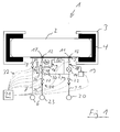
- a device 1 for vulcanizing tires comprises a vulcanization bellows 2 and a tire mold 3 (FIG. Fig. 1 ).
- the vulcanization bellows 2 is designed to heat and to form a green tire or an unvulcanized tire 4.
- When vulcanizing the green tire 4 is pressed on the Vulkanisationsbalg to the tire mold 3 and heated, whereby it receives its final shape.
- the Vulkanisationsbalg 2 is an approximately disc-shaped, deployable or inflatable rubber bellows whose outer contours and dimensions correspond to the interior of a tire. On the underside, the vulcanization bellows 2 has a circular Vulkanisationsbalgan gleichplatte 5 approximately in the middle.
- the Vulkanisationsbalgan gleichplatte 5 is provided with a lifting device (not shown) to arrange the Vulkanisationsbalg 2 in the tire mold 3.
- a lifting device (not shown) to arrange the Vulkanisationsbalg 2 in the tire mold 3.
- a material having good thermal conductivity such as a metal, such as a metal, is used. Aluminum or the like used.
- the lifting device is, for example, designed as a hydraulic piston-cylinder unit.
- a heating medium source 6 is connected via a Walkermediumzu111 Gustav 7 with the Vulkanisationsbalgan gleichplatte 5.
- a heating medium valve 8 is arranged in the Schumediumzu111.
- the heating medium source 6 is designed as an evaporator or as a device for supplying hot water. By means of the heating medium source 6 of the Vulkanisationsbalg 2 can be acted upon with steam and / or hot water.
- a discharge line 33 is connected.
- a discharge valve 34 is integrated.
- the Vulkanisationsbalgan gleichplatte 5 has a bypass line 9, via which a arranged in the interior of the Vulkanisationsbalges 2 medium in a circulation direction 10 is circulated.
- bypass line 9 forms on the Vulkanisationsbalgan gleichplatte 5 an inlet 11 in the bypass line 9 from.
- the other end of the bypass line 9 forms corresponding to the connection plate an outlet 12 from the bypass line 9.
- the circulation direction 10 leads from the inlet 11 of the bypass line 9 to the outlet 12.
- a bypass inlet valve 13 is arranged directly on the VulkanisationsbalganBankplatte 5.
- a pump 14 is provided in the bypass line 9.
- the pump is designed to circulate a medium from the interior of the vulcanization bladder 2 via the bypass line 9.
- a sensor 18 is arranged in the bypass line 9, which is connected to a detection device 19.
- the detection device 19 is an oxygen concentration measuring device.
- oxygen concentration measuring instruments or oxygen analyzers are available, for example, under the name SITRANS-SL from Siemens or else under the name Singlechannel Gasmonitor from MONICON Technology.
- a catalyst 15 is arranged in the bypass line 9 after the pump 14.
- the catalyst 15 is designed such that a reaction between oxygen and hydrogen is accelerated to water.
- the catalyst 15 is fixed directly on the vulcanization port plate 5 so that the catalyst 15 thermally contacts the vulcanization bellows plate 5.
- a first shut-off valve 16 is provided in the bypass line 9 in the direction of circulation 10.
- bypass line 9 is connected to the outlet of the vulcanization bellows 2 via a bypass outlet valve 17, which is arranged directly on the vulcanization bellows closure plate 5.
- the device 1 has a reducing gas source 20.
- the reducing gas source 20 is connected via a reducing gas supply line 21 to the bypass line 9 in the region between the pump 14 and the catalyst 15.
- a reducing gas valve 22 is provided in the reducing gas supply line 21, a reducing gas valve 22 is provided.
- the reducing gas source is a forming gas source in the present embodiment.
- the forming gas preferably consists of 95% by volume of nitrogen and 5% by volume of hydrogen.
- a compressed gas source 23 is connected via a Druckgaszu900 Koch 24 with the bypass line 9 in the region between the first shut-off valve 16 and the bypass outlet valve 17.
- the compressed gas supply line 24 is connected to the bypass line 9 in the region between the catalyst 15 and the pump 14 and the reducing gas valve 22.
- This line is referred to as connecting line 29.
- a third shut-off valve 30 is arranged in this connecting line 29.
- the compressed gas supply line 24 has a first line section 25 and a second line section 26.
- the first line section 25 extends from the compressed gas source 23 to the connecting line 29.
- the second line section 26 extends from the connecting line 29 to the bypass line 9.
- a compressed gas valve 27 is arranged in the first line section 25, a compressed gas valve 27 is arranged in the first line section 25, a compressed gas valve 27 is arranged in the first line section 25, a compressed gas valve 27 is arranged.
- the second line section 26 has a second shut-off valve 28.
- the compressed gas source is a nitrogen source.
- the tire mold 3 has an electric heater (not shown).
- a control device 31 is provided which is connected via control lines 32 to the valves, the pump, the detection device, the heating device and the lifting device.
- the Vulkanisationsbalgan gleichplatte 5 is trough-shaped or funnel-shaped (not shown), wherein in the lowest region of the Vulkanisationsbalgan gleichplatte 5, the discharge line 33 is arranged.
- This has the advantage that the Heating medium or water can be completely removed from the Vulkanisationsbalg 2, since it is after it condenses by itself to the lowest point of Vulkanisationsbalgan gleichplatte 5 runs. Thus, the water can not penetrate into the bypass line 9 and damage the catalyst 15.
- the bypass inlet valve 13 in the region of the inlet 11 and the bypass outlet valve 17 in the region of the outlet 12 are designed such that water drains from its surface and does not remain in the region of the valves 13, 17. If the Vulkanisationsbalgan gleichplatte 5 is flat, at least in the region of the discharge line 33, a small discharge funnel or a Abvantmulde (not shown) may be provided.
- a pipe section extending in the vertical direction is arranged on the inlet 11 and the outlet 12. These pipe sections can be purged with nitrogen and prevent heating medium from the interior of the vulcanization bladder 2 from damaging the catalyst. The filling with nitrogen is facilitated.
- the sensor 18 may also be arranged in the vulcanization bellows 2.
- a capillary line may also be provided, which is arranged in the vulcanization bellows 2 or in the bypass line 9, via which a gas sample is taken, which is then supplied to the detection device 19 for determining the concentration.
- control device 31 which controls the individual components of the device 1 via the control lines 32.
- the tire mold 3 is heated by the electric heater. Subsequently, a green tire 4 is inserted into the tire mold 3.
- the vulcanization bellows 2 is arranged centrally in the tire mold 3 or the green tire 4 by means of the lifting device.
- the vulcanization bellows 2 is filled with a heating medium from the heating medium source 6 via the opened heating medium valve 8 and the SchumediumzuSciencetechnisch 7 and thus unfolded. In this way, the green tire 4 is heated and pressed against the tire mold 3.
- the heating medium is discharged via the discharge line 10 from the Vulkanisationsbalg.
- the heating medium is then replaced by nitrogen.
- the discharge valve 34 is opened to remove the heating medium via the discharge line 33 from the Vulkanisationsbalg 2.
- the compressed gas valve 27 and the second shut-off valve are opened.
- the nitrogen flows through the open pressure gas valve 27 via the Druckgaszu slaughtertechnisch 24 from the compressed gas source 23 into the bypass line 9 and into the outlet 12 and thus in the Vulkanisationsbalg 2, where he displaces the heating medium from the Vulkanisationsbalg.
- Vulkanisationsbalg 2 By the nitrogen of Vulkanisationsbalg 2 is applied with a predetermined pressure of about 3 bar to 5 bar.
- the bypass input valve 13 can be opened briefly to flush away any residues of the heating medium which have accumulated in the region of the inlet 11. This heating medium, especially in the form of water could otherwise penetrate into the bypass line 9 and damage the catalyst 15.
- the vulcanization bellows 2 are initially charged only with nitrogen.
- the holding phase usually takes 6 to 10 minutes for normal car tires.
- the gas in particular nitrogen
- the bypass line 9 in the direction of circulation 10, whereby it reaches the oxidant sensor 18 is passed. It can also be provided to circulate the nitrogen permanently, with a low flow velocity via the bypass line 9.
- bypass inlet valve 13 and the first shut-off valve 16 are opened.
- the second and the third shut-off valve 28, 30 are closed as well as the compressed gas valve 27 and the reducing gas valve 22.
- the sensor 18 and the detection device 19 monitor the oxygen content in the nitrogen continuously or at intervals, for example, approximately once every 20 seconds or every 45 seconds and preferably at about one time per minute in accordance with the circulation rhythm.
- the concentration of oxidant or oxygen in the vulcanization bladder has a limit value of 0 ppm, 1 ppm, 2.5 ppm, 5 ppm, 10 ppm, 50 ppm, 100 ppm, 150 ppm resp
- the reducing gas valve 22 is opened, and forming gas and the hydrogen contained therein are supplied to the circulating medium via the reducing gas supply line.
- the hydrogen from the forming gas mixes with the remaining nitrogen and the contained therein Oxidant (oxygen).
- Oxidant oxygen
- This forming gas mixture i. the nitrogen, the hydrogen and the oxygen contained therein flow together through the catalyst 15.
- the hydrogen reacts with the oxygen to form water and is thus bound.
- a maximum of forming gas is supplied so that the hydrogen content in the forming gas mixture is less than 5% or less than 2.5% and in particular less than 1%. Otherwise, an explosive mixture would be provided and the device would have to be explosion-proof.
- the concentration of the oxidant is monitored regularly and reliably maintained at a non-critical level, so that there is no damage to the Vulkanisationsbalges 2 by oxygen contaminants.
- the concentration of oxidant or oxygen in the vulcanization bladder is then from 50 ppm to 25 ppm, or from 10 ppm to 5 ppm and preferably from 0 ppm to 5 ppm in the forming gas mixture.
- the nitrogen and / or the forming gas may also be provided to feed the nitrogen together with the forming gas via the catalyst 15 before being fed into the vulcanization bellows 2.
- the second shut-off valve 28 is then closed, the third shut-off valve 30 and the reduction gas valve 22 is opened.
- the forming gas flows from the reducing gas source 20 via the opened reducing gas valve 22 and the Reduktionsgaszu slaughtertechnisch 21.
- the nitrogen then flows together with the forming gas in the bypass line 9 and in the direction of circulation 10 via the catalyst 15.
- This Forming gas mixture then flows via the opened first shut-off valve 16 and the bypass outlet valve 27 into the vulcanization bellows 2.
- the vulcanization bellows 2 is acted upon after heating by the heating medium with a Formiergasgemisch instead of pure nitrogen.
- Such a method essentially corresponds to the method described above.
- forming gas is merely supplied together with the nitrogen to provide a forming gas mixture.
- the forming gas flows from the reducing gas source 20 via the opened reducing gas valve 22 and the Reduktionsgaszu111technisch 21 in the connecting line 29. From the connecting line 29, the forming gas flows through the open third shut-off valve 30 into the Druckgaszu ebooktechnisch 24. This mixes the forming gas with the nitrogen in the second line section 26 and is fed to the Vulkanisationsbalg together with the nitrogen. The mixing ensures a uniform hydrogen concentration in the vulcanization bellows 2. It is fed in about as much forming gas that the hydrogen content in the Formiergasgemisch in about 1 vol.%, Or 2 vol.% And at most 5 vol.% Is.
- the detection device can be dispensed with.
- the metered addition of hydrogen can, for example, be based on experience.
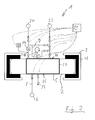
- the vulcanization bellows 2 is designed as an approximately circular-shaped tube and arranged around an approximately cylindrical Vulkanisationsbalgexcellent 5 around and connected thereto.
- the Vulkanisationsbalgodia 5 has a bottom 35 and an upper surface 36, which are interconnected via vertical struts 37.
- the Vulkanisationsbalgzi 5 is formed of a thermally highly conductive material such as. A metal such as aluminum or the like.
- the Vulkanisationsbalgites 5 is provided on the upper side with a lifting device (not shown).
- the underside of the Vulkanisationsbalg dis 5 is connected via corresponding connections with a Walkermediumzutechnologie Gustav 7 and with a discharge line 33.
- the connection may be made by connecting means (not shown), e.g. Cutting ring fittings, connectors, bayonet locks or other suitable connections made.
- a centering device (not shown) is provided to position the Schumediumzu1000technisch 7 and the discharge line 33 when lowering the Vulkanisationsbalges 2 corresponding to the terminals.
- the centering device may, for example, comprise three centering pins, which are brought into engagement with corresponding recesses when the vulcanization bellows carrier 5 is lowered.
- Such an arrangement has the advantage that not the danger is that the arranged in the bypass line 9 catalyst 15 can be damaged by heating medium or water.
- the reducing gas source 23 may be formed as a hydrogen source.
- a corresponding device is to be designed explosion-proof.
- the hydrogen content in the forming gas mixture is then less than 10% or less than 2.5% and preferably less than 5%.
- the device according to the invention can also be provided to arrange the catalyst 15 inside the Vulkanisationsbalges 2. However, it would then be useful to protect them via appropriate valves or flaps or the like from water or the heating medium to avoid damage.
- the catalyst 15 is arranged in the vulcanization bellows 2.
- a catalyst 15 used in this case is insensitive to the heating medium or to the water contained in the heating medium.
- the catalyst 15 is arranged in the vulcanization bellows 2 in the region of the vulcanization bellows closure plate 5.
- the nitrogen and the forming gas are in this case introduced into the vulcanization bellows in such a way that a forced flow is generated, so that during circulation the nitrogen, the forming gas and the oxidant are circulated via the catalyst 15 in a circulation direction 38.
- the senor 18 may also be arranged in the vulcanization bellows 2.
- a pressure regulator adjusted to a constant pressure may also be provided in the embodiments described. This has the advantage that the pressure in the vulcanization bellows remains constant and no valve has to be switched.
Landscapes
- Physics & Mathematics (AREA)
- Health & Medical Sciences (AREA)
- Oral & Maxillofacial Surgery (AREA)
- Thermal Sciences (AREA)
- Engineering & Computer Science (AREA)
- Mechanical Engineering (AREA)
- Moulds For Moulding Plastics Or The Like (AREA)
Abstract
Die Gemäß dem erfindungsgemäßen Verfahren zum Vulkanisieren von Reifen wird ein Vulkanisationsbalg (2) mit einem Druckgas beaufschlagt, um einen vorbestimmten Druck auf den zu vulkanisierenden Reifen (4) auszuüben. Zusätzlich zum Druckgas wird dem Vulkanisationsbalg (2) ein reduzierendes Gas zugeführt, wobei das Gemisch aus Druckgas und reduzierendem Gas ein Formiergas ist.
Description
- Die vorliegende Erfindung betrifft ein Verfahren und eine Vorrichtung zum Vulkanisieren von Reifen.
- Die Reifenvulkanisation erfolgt in Heizpressen, wobei ein Reifenrohling in geeignete Formsegmente eingesetzt und über einen Vulkanisationsbalg aufgeheizt und mit Druck beaufschlagt wird.
- Das Aufheizen erfolgt bei der Reifenvulkanisation meist durch Wasserdampf oder Heißwasser. Diese Heizmedien werden unter einem hohen Druck in den Vulkanisationsbalg eingebracht. Zum Aufheizen der Heizmedien und um die Temperatur im Vulkanisationsbalg aufrechtzuerhalten ist aufgrund des hohen Wärmeübergangs des Heizmediums viel Energie erforderlich.
- Nach der Heizphase wird das Heizmedium im Vulkanisationsbalg in einer Haltephase durch Stickstoff ersetzt und der Reifenrohling erhält seine endgültige Form. Dem gasförmigen Stickstoff muss aufgrund seiner geringen Wärmekapazität nur wenig Energie zugeführt werden, um den Reifenrohling bzw. den Vulkanisationsbalg auf Temperatur zu halten.
- Der Vulkanisationsbalg drückt den Reifenrohling bspw. mit etwa 12 bar gegen eine Reifenform. Der Vorgang dauert je nach Reifenkategorie, bei einer Temperatur von 165 °C bis 200°C, zwischen 9 und 17 Minuten. Die Vulkanisation löst eine chemische Reaktion aus, wobei Kautschuk und Chemikalien durch Schwefel verbunden werden. Es bilden sich vernetzte Molekülketten aus, wodurch elastischer Gummi entsteht. In einem abschließenden Fertigungsverfahren werden überstehende Gummiteile entfernt.
- Die Lebensdauer eines Vulkanisationsbalges ist ein kritischer Faktor in der Reifenherstellung. Der Vulkanisationsbalg degradiert über seine Lebensdauer. Diese Degradation ist insbesondere auf Sauerstoff, der während des Aufheizens über das Heizmedium in den Vulkanisationsbalg eingebracht wird, zurückzuführen. Der Sauerstoff kann im Heizdampf oder im Heißwasser in gelöster Form vorliegen und während der Heizphase entweichen. Der Sauerstoff kann auch auf Grund von Undichtigkeiten bei der Stickstoffzuführung während der Haltephase in den Vulkanisationsbalg gelangen. Durch den molekularen Sauerstoff werden die vernetzten Molekülketten im Gummi des Vulkanisationsbalgs aufgebrochen, wodurch der Gummi altert und schließlich reißt. Dies wird als oxygen reversion bezeichnet.
- Durch Einbringen von chemischen Antioxidantien in das Material des Vulkanisationsbalges bei der Herstellung, bspw. durch fluorisieren, wird versucht diesen Prozess zu verlangsamen. Allerdings werden diese Antioxidantien durch Wasserstoff in den Heiz- und Druckmedien aus dem Vulkanisationsbalg gelöst. Sobald die Antioxidantien entfernt sind, greift der molekulare Sauerstoff den Gummi des Vulkanisationsbalges an.
- Da die Produktionskosten bei der Reifenherstellung einen wesentlichen Faktor darstellen und Vulkanisationsbälge relativ teuer sind, wird versucht die Lebensdauer der Vulkanisationsbälge zu erhöhen.
- Aufgabe der vorliegenden Erfindung ist es daher, ein Verfahren bereitzustellen, bei dem die Lebensdauer eines Vulkanisationsbalges verlängert wird und somit die Produktionskosten bei der Reifenherstellung gesenkt werden können.
- Die Erfindung weist zur Lösung dieser Aufgabe die im Patentanspruch 1 angegebenen Merkmale auf. Vorteilhafte Ausgestaltungen hiervon sind in den weiteren Ansprüchen angegeben.
- Gemäß dem erfindungsgemäßen Verfahren zum Vulkanisieren von Reifen wird ein Vulkanisationsbalg mit einem Druckgas beaufschlagt, um einen vorbestimmten Druck auf den zu vulkanisierenden Reifen auszuüben. Zusätzlich zum Druckgas wird dem Vulkanisationsbalg ein reduzierendes Gas zugeführt, wobei das Gemisch aus Druckgas und reduzierendem Gas ein Formiergasgemisch ist.
- Unter Formiergasgemisch wir im Rahmen der vorliegenden Erfindung ein Gemisch verstanden das Stickstoff und Wasserstoff enthält.
- Im Vulkanisationsbalg kann durch ein Heizmedium, durch Verunreinigungen im Druckgas und/oder durch Undichtigkeiten im System ein Oxidans vorhanden sein. Dieses Oxidans ist in der Regel molekularer Sauerstoff. Das reduzierende Gas, insbesondere Wasserstoff, reagiert mit dem im Vulkanisationsbalg vorhandenen molekularen Sauerstoff zu Wasser. Dies verhindert, dass die vernetzten Molekülketten im Gummi des Vulkanisationsbalges durch den molekularen Sauerstoff aufgebrochen werden, wodurch der Gummi altert und/oder spröde wird und schließlich reißt. Somit bleibt der Gummi durch Einbringen eines reduzierenden Gases länger elastisch wodurch sich die Lebensdauer eines Vulkanisationsbalges erheblich verlängert.
- Das reduzierende Gas kann unter Zuhilfenahme eines Katalysators mit dem im Vulkanisationsbalg enthaltenen Oxidans reagieren. Durch die Verwendung eines Katalysators kann das reduzierende Gas effizient Oxidans binden und dadurch den Vulkanisationsbalg besser vor dem schädlichen Einfluss von Sauerstoff schützen
- Im Vulkanisationsbalg kann eine Konzentration des Oxidans detektiert werden. Nach Maßgabe der detektierten Konzentration des Oxidans ist vorgesehen reduzierendes Gas dem Druckgas zuzuführen. Hierdurch wird sichergestellt, dass eine kritische Konzentration des Oxidans im Vulkanisationsbalg nicht überschritten wird. Zudem wird nur so viel reduzierendes Gas wie nötig ist, um das Oxidans zu binden zugeführt. Dies spart Kosten, da das reduzierende Gas, vorzugsweise Formiergas oder auch Wasserstoff, teuer ist.
- Ab einem Grenzwert der Konzentration des Oxidans im Vulkanisationsbalg von 0 ppm bzw. 1 ppm bzw. 2,5 ppm bzw. 5 bzw. 10 ppm bzw. 50 ppm bzw. 100 ppm bzw. 250 ppm bzw. 500 ppm bzw. 1000 ppm wird reduzierendes Gas zugeführt.
- Versuche haben gezeigt, dass eine Konzentration von 1 % bzw. 10000 ppm Sauerstoff im Vulkanisationsbalg dessen Lebensdauer auf 20% bis 50 % gegenüber einem Betrieb mit Heißwasser reduziert. Eine Konzentration von 0,1% bzw. 1000 ppm Sauerstoff im Vulkanisationsbalg reduziert dessen Lebensdauer um 10% bis 20 %. Bereits bei einer Konzentration von 50 ppm Sauerstoff im Vulkanisationsbalg erhöht sich die Lebensdauer des Vulkanisationsbalgs um 10% bis 20 %. Bei einer Konzentration von 5 ppm Sauerstoff im Vulkanisationsbalg erhöht sich die Lebensdauer des Vulkanisationsbalgs um 20% bis 50 % gegenüber einem Betrieb mit Heißwasser. Daher ist erfindungsgemäß vorgesehen, dass immer so viel reduzierendes Gas zugeführt wird, dass die Konzentration an Oxidans bzw. Sauerstoff im Vulkanisationsbalg von 50 ppm bis 25 ppm, bzw. von 15 ppm bis 5 ppm, bzw. von 8 ppm bis 5 ppm und vorzugsweise von 0 ppm bis 1 ppm beträgt. Durch derart niedrige Sauerstoffkonzentrationen im Vulkanisationsbalg wird dessen Lebensdauer erhöht.
- Das im Vulkanisationsbalg befindliche Formiergasgemisch kann über eine mit dem Vulkanisationsbalg verbundene Bypassleitung, in der der Katalysator angeordnet ist, zirkuliert werden. Hieraus ergibt sich der Vorteil, dass der Katalysator nicht im Vulkanisationsbalg angeordnet werden muss, um das Oxidans und das reduzierende Gas zu kontaktieren. Da Katalysatoren empfindlich im Hinblick auf Feuchtigkeit sein können, kann der Katalysator durch das Heizmedium beschädigt werden, würde man ihn im Vulkanisationsbalg anordnen.
- Sollte der Katalysator nicht empfindlich auf Feuchtigkeit sein ist es auch möglich diesen im Vulkanisationsbalg anzuordnen.
- Die Konzentration des Oxidans kann im Vulkanisationsbalg detektiert werden. Dass die Konzentration im Vulkanisationsbalg detektiert wird, bedeutet im Rahmen der vorliegenden Erfindung nicht, dass die Konzentration direkt im Vulkanisationsbalg detektiert werden muss. Sie kann bspw. auch in der Bypassleitung detektiert werden. Es kann aber auch ein Sensor im Vulkanisationsbalg angeordnet sein, um die Konzentration direkt dort zu messen. Nach Maßgabe der detektierten Konzentration des Oxidans kann Formiergas bzw. Formiergasgemisch über die Bypassleitung, in der der Katalysator angeordnet ist, zirkuliert werden, um das Oxidans mit reduzierendem Gas zu binden.
- Es ist zudem eine Vorrichtung zum Vulkanisieren von Reifen vorgesehen. Diese umfasst einen Vulkanisationsbalg, wobei der Vulkanisationsbalg mit einer Druckgasquelle zum Beaufschlagen des Vulkanisationsbalges mit einem Druckgas ausgebildet ist, um einen vorbestimmten Druck auf den zu vulkanisierenden Reifen auszuüben. Die Vorrichtung weist eine Reduktionsgasquelle auf, um dem Vulkanisationsbalg ein reduzierendes Gases zuzuführen, wobei das Gemisch aus Druckgas und reduzierendem Gas ein Formiergasgemisch ist.
- Die Erfindung wird im folgenden anhand der Zeichnungen näher erläutert. Diese zeigen in:
- Fig. 1
- eine erfindungsgemäße Vorrichtung zum Vulkanisieren von Reifen gemäß einem ersten Ausführungsbeispiel schematisch in einer seitlich geschnittenen Ansicht,
- Fig. 2
- eine erfindungsgemäße Vorrichtung zum Vulkanisieren von Reifen gemäß einem zweiten Ausführungsbeispiel schematisch in einer seitlich geschnittenen Ansicht, und
- Fig. 3
- eine erfindungsgemäße Vorrichtung zum Vulkanisieren von Reifen gemäß einem dritten Ausführungsbeispiel schematisch in einer seitlich geschnittenen Ansicht.
- Eine erfindungsgemäße Vorrichtung 1 zum Vulkanisieren von Reifen umfasst einen Vulkanisationsbalg 2 und eine Reifenform 3 (
Fig. 1 ). Der Vulkanisationsbalg 2 ist zum Erwärmen und zum Ausformen eines Reifenrohlings bzw. eines unvulkanisierten Reifens 4 ausgebildet. Beim Vulkanisieren wird der Reifenrohling 4 über den Vulkanisationsbalg an die Reifenform 3 angepresst und aufgeheizt, wodurch er seine endgültige Form erhält. - Der Vulkanisationsbalg 2 ist ein in etwa scheibenförmiger, entfaltbarer bzw. aufblähbarer Gummibalg dessen äußere Konturen und Abmessungen dem Inneren eines Reifens entsprechen. Unterseitig weist der Vulkanisationsbalg 2 in etwa mittig eine kreisförmige Vulkanisationsbalganschlussplatte 5 auf.
- Die Vulkanisationsbalganschlussplatte 5 ist mit einer Hubeinrichtung (nicht dargestellt) versehen, um den Vulkanisationsbalg 2 in der Reifenform 3 anzuordnen. Als Material für die Vulkanisationsbalganschlussplatte 5 wird ein thermisch gut leitendes Material, wie bspw. ein Metall, wie z.B. Aluminium oder dergleichen verwendet. Die Hubeinrichtung ist bspw. als hydraulische Kolben-Zylinder-Einheit ausgebildet.
- Eine Heizmediumquelle 6 ist über eine Heizmediumzuführleitung 7 mit der Vulkanisationsbalganschlussplatte 5 verbunden. In der Heizmediumzuführleitung 7 ist ein Heizmediumventil 8 angeordnet. Die Heizmediumquelle 6 ist als Verdampfer oder als Einrichtung zum Zuführen von Heißwasser ausgebildet. Mittels der Heizmediumquelle 6 ist der Vulkanisationsbalg 2 mit Dampf und/oder Heißwasser beaufschlagbar.
- An der Vulkanisationsbalganschlussplatte 5 ist eine Abführleitung 33 angeschlossen. In die Abführleitung 33 ist ein Abführventil 34 integriert.
- Die Vulkanisationsbalganschlussplatte 5 weist eine Bypassleitung 9 auf, über die ein im Inneren des Vulkanisationsbalges 2 angeordnetes Medium in einer Zirkulationsrichtung 10 zirkulierbar ist.
- Ein Ende der Bypassleitung 9 bildet an der Vulkanisationsbalganschlussplatte 5 einen Einlass 11 in die Bypassleitung 9 aus. Das andere Ende der Bypassleitung 9 bildet entsprechend an der Anschlussplatte einen Auslass 12 aus der Bypassleitung 9 aus. Die Zirkulationsrichtung 10 führt vom Einlass 11 der Bypassleitung 9 zum Auslass 12.
- Am Einlass 11 der Bypassleitung 9 ist unmittelbar an der Vulkanisationsbalganschlussplatte 5 ein Bypasseinlassventil 13 angeordnet.
- Nach dem Bypasseinlassventil 13 ist in der Bypassleitung 9 eine Pumpe 14 vorgesehen. Die Pumpe ist zum Zirkulieren eines Mediums aus dem Inneren des Vulkanisationsbalges 2 über die Bypassleitung 9 ausgebildet.
- Im Bereich zwischen dem Bypasseinlassventil 13 und der Pumpe 14 ist in der Bypassleitung 9 ein Sensor 18 angeordnet, der mit einer Detektionseinrichtung 19 verbunden ist. Die Detektionseinrichtung 19 ist ein Sauerstoffkonzentrationsmessgerät. Derartige Sauerstoffkonzentrationsmessgeräte bzw. Sauerstoffanalysatoren sind bspw. unter der Bezeichnung SITRANS-SL der Firma Siemens oder auch unter der Bezeichnung Singlechannel Gasmonitor von der Firma MONICON Technology erhältlich.
- In Zirkulationsrichtung 10 ist nach der Pumpe 14 ein Katalysator 15 in der Bypassleitung 9 angeordnet. Der Katalysator 15 ist derart ausgebildet, dass eine Reaktion zwischen Sauerstoff und Wasserstoff zu Wasser beschleunigt wird. Der Katalysator 15 ist direkt auf der Vulkanisationsanschlussplatte 5 fixiert, so dass der Katalysator 15 die Vulkanisationsbalganschlussplatte 5 thermisch kontaktiert.
- Nach dem Katalysator 15 ist in Zirkulationsrichtung 10 ein erstes Absperrventil 16 in der Bypassleitung 9 vorgesehen.
- Nach dem ersten Absperrventil 16 ist die Bypassleitung 9 über ein Bypassausgangsventil 17, welches unmittelbar an der Vulkanisationsbalganschlussplatte 5 angeordnet ist, mit dem Ausgang des Vulkanisationsbalg 2 verbunden.
- Die Vorrichtung 1 weist eine Reduktionsgasquelle 20 auf. Die Reduktionsgasquelle 20 ist über eine Reduktionsgaszuführleitung 21 mit der Bypassleitung 9 im Bereich zwischen der Pumpe 14 und dem Katalysator 15 verbunden. In der Reduktionsgaszuführleitung 21 ist ein Reduktionsgasventil 22 vorgesehen. Die Reduktionsgasquelle ist im vorliegenden Ausführungsbeispiel eine Formiergasquelle. Das Formiergas besteht vorzugsweise aus 95 Vol.% Stickstoff und 5 Vol.% Wasserstoff.
- Eine Druckgasquelle 23 ist über eine Druckgaszuführleitung 24 mit der Bypassleitung 9 im Bereich zwischen dem ersten Absperrventil 16 und dem Bypassausgangsventil 17 verbunden.
- Die Druckgaszuführleitung 24 ist mit der Bypassleitung 9 im Bereich zwischen dem Katalysator 15 und der Pumpe 14 bzw. dem Reduktionsgasventil 22 verbunden. Diese Leitung wird als Verbindungsleitung 29 bezeichnet. In dieser Verbindungsleitung 29 ist ein drittes Absperrventil 30 angeordnet.
- Die Druckgaszuführleitung 24 weist einen ersten Leitungsabschnitt 25 und einen zweiten Leitungsabschnitt 26 auf. Der erste Leitungsabschnitt 25 erstreckt sich von der Druckgasquelle 23 bis zur Verbindungsleitung 29. Der zweite Leitungsabschnitt 26 erstreckt sich von der Verbindungsleitung 29 bis zur Bypassleitung 9. Im ersten Leitungsabschnitt 25 ist ein Druckgasventil 27 angeordnet. Der zweite Leitungsabschnitt 26 weist ein zweites Absperrventil 28 auf. Die Druckgasquelle ist eine Stickstoffquelle.
- Die Reifenform 3 weist eine elektrische Heizeinrichtung (nicht dargestellt) auf.
- Es ist eine Steuereinrichtung 31 vorgesehen, die über Steuerleitungen 32 mit den Ventilen, der Pumpe, der Detektionseinrichtung, der Heizeinrichtung und der Hubeinrichtung verbunden ist.
- Vorzugsweise ist die Vulkanisationsbalganschlussplatte 5 mulden- bzw. trichterförmig (nicht dargestellt) ausgebildet, wobei im tiefsten Bereich der Vulkanisationsbalganschlussplatte 5 die Abführleitung 33 angeordnet ist. Dies hat den Vorteil, dass das Heizmedium bzw. Wasser vollständig aus dem Vulkanisationsbalg 2 abgeführt werden kann, da es nachdem es kondensiert ist von selbst zum tiefsten Punkt der Vulkanisationsbalganschlussplatte 5 läuft. Somit kann das Wasser nicht in die Bypassleitung 9 eindringen und den Katalysator 15 schädigen. Vorteilhafterweise sind das Bypasseinlassventil 13 im Bereich des Einlasses 11 und das Bypassauslassventil 17 im Bereich des Auslasses 12 derart ausgestaltet, dass Wasser von deren Oberfläche abläuft und nicht in dem Bereich der Ventile 13, 17 verbleibt. Wenn die Vulkanisationsbalganschlussplatte 5 eben ausgebildet ist kann zumindest im Bereich der Abführleitung 33 ein kleiner Abführtrichter bzw. eine Abführmulde (nicht dargestellt) vorgesehen sein.
- Weiterhin kann auch vorgesehen sein, dass auf dem Einlass 11 und dem Auslass 12 jeweils ein sich in vertikaler Richtung erstreckender Rohrabschnitt angeordnet ist. Diese Rohrabschnitte sind mit Stickstoff spülbar und verhindern, dass Heizmedium aus dem Inneren des Vulkanisationsbalges 2 den Katalysator beschädigt. Das Befüllen mit Stickstoff wird dadurch erleichtert.
- Der Sensor 18 kann auch im Vulkanisationsbalg 2 angeordnet sein. Es kann auch eine Kapillarleitung vorgesehen sein, die im Vulkanisationsbalg 2 oder in der Bypassleitung 9 angeordnet ist, über die eine Gasprobe entnommen wird, die dann der Detektionseinrichtung 19 zur Bestimmung der Konzentration zugeführt wird.
- Im Folgenden wird das erfindungsgemäße Verfahren zum Vulkanisieren von Reifen beschrieben.
- Das gesamte Verfahren wird von der Steuereinrichtung 31 automatisch gesteuert, die über die Steuerleitungen 32 die einzelnen Komponenten der Vorrichtung 1 ansteuert.
- Zunächst wird die Reifenform 3 mittels der elektrischen Heizeinrichtung aufgeheizt. Anschließend wird ein Reifenrohling 4 in die Reifenform 3 eingelegt.
- Der Vulkanisationsbalg 2 wird mittels der Hubeinrichtung zentral mittig in der Reifenform 3 bzw. dem Reifenrohling 4 angeordnet.
- Anschließend wird der Vulkanisationsbalg 2 mit einem Heizmedium aus der Heizmediumquelle 6 über das geöffnete Heizmediumventil 8 und die Heizmediumzuführleitung 7 befüllt und somit entfaltet. Auf diese Weise wird der Reifenrohling 4 aufgeheizt und an die Reifenform 3 angepresst.
- Nachdem eine Temperatur von ca. 150 °C bis 180 °C und ein Druck von ca. 3 bar bis 5 bar erreicht ist und der Reifenrohling die entsprechende Temperatur erreicht hat, wird das Heizmedium über die Abführleitung 10 aus dem Vulkanisationsbalg abgeführt.
- Das Heizmedium wird dann durch Stickstoff ersetzt.
- Hierfür wird das Abführventil 34 geöffnet, um das Heizmedium über die Abführleitung 33 aus dem Vulkanisationsbalg 2 abzuführen. Gleichzeitig werden das Druckgasventil 27 und das zweite Absperrventil geöffnet. Der Stickstoff strömt durch das geöffnete Druckgasventil 27 über die Druckgaszuführleitung 24 aus der Druckgasquelle 23 in die Bypassleitung 9 und in den Auslass 12 und somit in den Vulkanisationsbalg 2, wo er das Heizmedium aus dem Vulkanisationsbalg verdrängt.
- Durch den Stickstoff wird der Vulkanisationsbalg 2 mit einem vorbestimmten Druck von ca. 3 bar bis 5 bar beaufschlagt.
- Wenn das Heizmedium vollständig aus dem Vulkanisationsbalg abgeführt ist, kann das Bypasseingangsventil 13 kurz geöffnet werden, um Reste des Heizmediums, die sich im Bereich des Einlasses 11 angesammelt haben wegzuspülen. Dieses Heizmedium insbesondere in Form von Wasser könnte ansonsten in die Bypassleitung 9 eindringen und den Katalysator 15 beschädigen.
- Wenn der vorbestimmte Druck erreicht ist wird das Druckgasventil 27 geschlossen.
- Gemäß dem ersten Ausführungsbeispiel des Verfahrens ist vorgesehen den Vulkanisationsbalg 2 zunächst nur mit Stickstoff zu beaufschlagen.
- Die Haltephase dauert bei normalen PKW Reifen in der Regel 6 bis 10 Minuten.
- Während dieser Zeit wird in etwa ein Mal alle 20 Sekunden bzw. alle 45 Sekunden und vorzugsweise in etwa ein Mal pro Minute das Gas, insbesondere Stickstoff, intervallweise aus dem Inneren des Vulkanisationsbalges 2 über die Bypassleitung 9 in Zirkulationsrichtung 10 zirkuliert, wodurch er am Oxidanssensor 18 vorbeigeführt wird. Es kann auch vorgesehen sein, den Stickstoff permanent, mit einer geringen Strömungsgeschwindigkeit über die Bypassleitung 9 zu zirkulieren.
- Um den Stickstoff zu zirkulieren werden das Bypasseinlassventil 13 und das erste Absperrventil 16 geöffnet. Das zweite und das dritte Ansperrventil 28, 30 sind ebenso wie das Druckgasventil 27 und das Reduktionsgasventil 22 geschlossen.
- Anschließend wird die Pumpe 14 eingeschalten und das Bypassauslassventil 17 geöffnet.
- Dadurch werden der Stickstoff und das Oxidans bzw. Sauerstoff über die Bypassleitung 9 zirkuliert.
- Der Sensor 18 und die Detektionseinrichtung 19 überwachen permanent oder intervallweise bspw. in etwa ein Mal alle 20 Sekunden bzw. alle 45 Sekunden und vorzugsweise in etwa ein Mal pro Minute entsprechend dem Zirkulationsrythmus den Sauerstoffgehalt im Stickstoff.
- Wenn die Konzentration an Oxidans bzw. Sauerstoff im Vulkanisationsbalg bei der Messung einen Grenzwert von von 0 ppm bzw. 1 ppm bzw. 2,5 ppm bzw. 5 ppm bzw. 10 ppm bzw. 50 ppm bzw. 100 ppm bzw. 150 ppm bzw. 200 ppm bzw. 250 ppm im Stickstoff überschreitet wird das Reduktionsgasventil 22 geöffnet und Formiergas und der darin enthaltene Wasserstoff werden über die Reduktionsgaszuführleitung dem zirkulierenden Medium zugeführt. In der Bypassleitung 9 vermischt sich der Wasserstoff aus dem Formiergas mit dem restlichen Stickstoff und dem darin enthaltenen Oxidans (Sauerstoff). Hierdurch wird ein Formiergasgemisch ausgebildet dessen Wasserstoffkonzentration unter 5 Vol.% beträgt und das Oxidans enthält.
- Dieses Formiergasgemisch, d.h. der Stickstoff ,der Wasserstoff und der darin enthaltene Sauerstoff strömen zusammen über den Katalysator 15. Dadurch, dass der Katalysator 15 die Vulkanisationsbalganschlussplatte 5 thermisch kontaktiert wird er erwärmt und weist durch die hohe Temperatur und den hohen Druck des Mediums im Vulkanisationsbalg 2 und in der Bypassleitung 9 ausgezeichnete Reaktionsbedingungen auf. Im Bereich des Katalysators 15 reagiert der Wasserstoff mit dem Sauerstoff zu Wasser und wird somit gebunden. Es wird jedoch maximal soviel Formiergas zugeführt, dass der Wasserstoffanteil im Formiergasgemisch weniger als 5 % bzw. weniger als 2,5 % und insbesondere weniger als 1 % beträgt. Andernfalls würde ein explosionsfähiges Gemisch bereitgestellt werden und die Vorrichtung müsste explosionsgeschützt ausgebildet werden.
- Durch die intervallweise Probenentnahme wird die Konzentration des Oxidans regelmäßig überwacht und zuverlässig auf einem unkritischen Niveau gehalten, so dass es zu keiner Schädigung des Vulkanisationsbalges 2 durch Sauerstoffverunreinigungen kommt. Die Konzentration an Oxidans bzw. Sauerstoff im Vulkanisationsbalg beträgt dann von 50 ppm bis 25 ppm, bzw. von 10 ppm bis 5 ppm und vorzugsweise von 0 ppm bis 5 ppm im Formiergasgemisch.
- Sollte aufgrund von Undichtigkeiten im System der Stickstoff und/oder das Formiergas zu viel Sauerstoff enthalten, kann auch vorgesehen sein den Stickstoff zusammen mit dem Formiergas vor dem Zuführen in den Vulkanisationsbalg 2 über den Katalysator 15 zu führen. Hierfür wird dann das zweite Absperrventil 28 geschlossen, das dritte Absperrventil 30 und das Reduktiongasventil 22 geöffnet. Das Formiergas strömt aus der Reduktionsgasquelle 20 über das geöffnete Reduktionsgasventil 22 und die Reduktionsgaszuführleitung 21. Der Stickstoff strömt dann zusammen mit dem Formiergas in die Bypassleitung 9 und in Zirkulationsrichtung 10 über den Katalysator 15. Dadurch wird der Sauerstoff durch den im Formiergas enthaltenen Wasserstoff gebunden und kann den Vulkanisationsbalg 2 nicht mehr schädigen. Dieses Formiergasgemisch strömt dann über das geöffnete erste Absperrventil 16 und das Bypassausgangsventil 27 in den Vulkanisationsbalg 2.
- Gemäß einem zweiten Ausführungsbeispiel des erfindungsgemäßen Verfahrens wird der Vulkanisationsbalg 2 nach dem Aufheizen durch das Heizmedium mit einem Formiergasgemisch an Stelle von reinem Stickstoff beaufschlagt.
- Ein derartiges Verfahren entspricht im Wesentlichen dem oben beschriebenen Verfahren. Beim erstmaligen Zuführen von Stickstoff wird lediglich gemeinsam mit dem Stickstoff Formiergas zugeführt, um ein Formiergasgemisch bereitzustellen.
- Das Formiergas strömt aus der Reduktionsgasquelle 20 über das geöffnete Reduktionsgasventil 22 und die Reduktionsgaszuführleitung 21 in die Verbindungsleitung 29. Von der Verbindungsleitung 29 strömt das Formiergas über das geöffnete dritte Absperrventil 30 in die Druckgaszuführleitung 24. Dadurch vermischt sich das Formiergas mit dem Stickstoff im zweiten Leitungsabschnitt 26 und wird zusammen mit dem Stickstoff dem Vulkanisationsbalg zugeführt. Durch die Vermischung wird eine gleichmäßige Wasserstoffkonzentration im Vulkanisationsbalg 2 sichergestellt. Es wird in etwa so viel Formiergas zugeführt, dass der Wasserstoffanteil im Formiergasgemisch in etwa 1 Vol.%, bzw. 2 Vol.% und maximal 5 Vol.% beträgt.
- Gemäß diesem Ausführungsbeispiel kann auf die Detektionseinrichtung verzichtet werden. Die Zudosierung von Wasserstoff kann bspw. anhand von Erfahrungswerten erfolgen.
- In beiden Fällen ist es notwendig das Medium über den Katalysator zu zirkulieren, um das Oxidans zu binden.
- Selbstverständlich kann auch eine Detektionseinrichtung 19 mit Sensor 18 vorgesehen sein, wobei die restlichen Verfahrensschritte den oben beschriebenen entsprechen.
- Im Folgenden wird ein zweites Ausführungsbeispiel (
Fig. 2 ) der erfindungsgemäßen Vorrichtung beschrieben. Gleiche Bauteile sind mit den gleichen Bezugszeichen versehen. - Der Vulkanisationsbalg 2 ist als in etwa kreisringförmiger Schlauch ausgebildet und um einen in etwa zylinderförmigen Vulkanisationsbalgträger 5 herum angeordnet und mit diesem verbunden.
- Der Vulkanisationsbalgträger 5 weist eine Unterseite 35 und eine Oberseite 36 auf, die über Vertikalstreben 37 miteinander verbunden sind. Der Vulkanisationsbalgträger 5 ist aus einem thermisch gut leitenden Material wie bspw. einem Metall wie Aluminium oder dergleichen ausgebildet.
- Der Vulkanisationsbalgträger 5 ist oberseitig mit einer Hubeinrichtung (nicht dargestellt) versehen.
- Die Unterseite des Vulkanisationsbalgträgers 5 ist über entsprechende Anschlüsse mit einer Heizmediumzuführleitung 7 und mit einer Abführleitung 33 verbindbar. Die Verbindung kann durch Verbindungsmittel (nicht dargestellt), wie z.B. Schneidringverschraubungen, Steckverbindungen, Bajonettverschlüsse oder andere geeignete Verbindungen, erfolgen.
- Weiterhin ist eine Zentriereinrichtung (nicht dargestellt) vorgesehen, um die Heizmediumzuführleitung 7 und die Abführleitung 33 beim Absenken des Vulkanisationsbalges 2 entsprechend den Anschlüssen zu positionieren. Die Zentriereinrichtung kann bspw. drei Zentrierstifte umfassen, die beim Absenken des Vulkanisationsbalgträgers 5 mit entsprechenden Ausnehmungen in Eingriff gebracht werden.
- Die übrigen Bauteile der Vorrichtung 1, die gemäß dem ersten Ausführungsbeispiel unterhalb der Vulkanisationsbalganschlussplatte 5 angeordnet sind, sind gemäß dem zweiten Ausführungsbeispiel auf der Oberseite 36 des Vulkanisationsbalgträgers 5 angeordnet. Eine derartige Anordnung weist den Vorteil auf, dass nicht die Gefahr besteht, dass der in der Bypassleitung 9 angeordnete Katalysator 15 durch Heizmedium bzw. Wasser beschädigt werden kann.
- In einer weiteren Ausführungsform der erfindungsgemäßen Vorrichtung 1 kann die Reduktionsgasquelle 23 als Wasserstoffquelle ausgebildet sein. Allerdings ist eine entsprechende Vorrichtung explosionsgeschützt auszubilden. Der Wasserstoffanteil im Formiergasgemisch beträgt dann weniger als 10 % bzw. weniger als 2,5 % und vorzugsweise weniger als 5 %.
- Es kann auch vorgesehen sein, den Vulkanisationsbalg lediglich mit Formiergas zu beaufschlagen, was allerdings mit höheren Kosten verbunden ist.
- In einer weiteren Ausführungsform der erfindungsgemäßen Vorrichtung kann auch vorgesehen sein, den Katalysator 15 im Inneren des Vulkanisationsbalges 2 anzuordnen. Allerdings wäre es dann zweckmäßig diesen über entsprechende Ventile oder Klappen oder dergleichen vor Wasser bzw. dem Heizmedium zu schützen, um eine Beschädigung zu vermeiden.
- Im Folgenden wird ein drittes Ausführungsbeispiel (
Fig. 3 ) der erfindungsgemäßen Vorrichtung beschrieben. Gleiche Bauteile sind mit den gleichen Bezugszeichen versehen. - Gemäß diesem Ausführungsbeispiel ist der Katalysator 15 im Vulkanisationsbalg 2 angeordnet. Ein hierbei verwendeter Katalysator 15 ist unempfindlich gegen das Heizmedium bzw. gegen das im Heizmedium enthaltene Wasser.
- Der Katalysator 15 ist im Vulkanisationsbalg 2 im Bereich der Vulkanisationsbalganschlussplatte 5 angeordnet.
- Der Stickstoff und das Formiergas werden hierbei derart in den Vulkanisationsbalg eingebracht, dass eine Zwangsströmung erzeugt wird, so dass beim Zirkulieren der Stickstoff, das Formiergas und das Oxidans über den Katalysator 15 in einer Zirkulationsrichtung 38 zirkuliert werden.
- Bei einer derartigen Vorrichtung kann der Sensor 18 auch im Vulkanisationsbalg 2 angeordnet sein.
- Bei der Verwendung eines im Hinblich auf Heizwasser unempfindlichen Katalaysators sind auch einfachere Aufbauten als die oben beschriebenen möglich, da auf die Einrichtungen, die ein Eindringen von Wasser in den Katalysator verhindern, verzichtet werden kann.
- Alternativ kann bei den beschriebenen Ausführungsbeispielen an Stelle des Abführventils 34 auch ein auf einen konstanten Druck eingestellter Druckregler vorgesehen sein. Dies hat den Vorteil, dass der Druck im Vulkanisationsbalg konstant bleibt und kein Ventil geschaltet werden muss.
-
- 1
- Vorrichtung
- 2
- Vulkanisationsbalg
- 3
- Reifenform
- 4
- Reifenrohling
- 5
- Vulkanisationsbalganschlussplatte
- 6
- Heizmediumquelle
- 7
- Heizmediumzuführleitung
- 8
- Heizmediumventil
- 9
- Bypassleitung
- 10
- Zirkulationsrichtung
- 11
- Einlass
- 12
- Auslass
- 13
- Bypasseinlassventil
- 14
- Pumpe
- 15
- Katalysator
- 16
- Erstes Absperrventil
- 17
- Bypassauslassventil
- 18
- Sensor
- 19
- Detektionseinrichtung
- 20
- Reduktionsgasquelle
- 21
- Reduktionsgaszuführleitung
- 22
- Reduktionsgasventil
- 23
- Druckgasquelle
- 24
- Druckgaszuführleitung
- 25
- Erster Leitungsabschnitt
- 26
- Zweiter Leitungsabschnitt
- 27
- Druckgasventil
- 28
- Zweites Absperrventil
- 29
- Verbindungsleitung
- 30
- Drittes Absperrventil
- 31
- Steuereinrichtung
- 32
- Steuerleitungen
- 33
- Abführleitung
- 34
- Abführventil
- 35
- Unterseite
- 36
- Oberseite
- 37
- Vertikalstreben
- 38
- Zirkulationsrichtung
Claims (14)
- Verfahren zum Vulkanisieren von Reifen bei dem ein Vulkanisationsbalg (2) mit einem Druckgas beaufschlagt wird, um einen vorbestimmten Druck auf den zu vulkanisierenden Reifen (4) auszuüben,
dadurch gekennzeichnet,
dass dem Vulkanisationsbalg (2) zusätzlich zum Druckgas ein reduzierendes Gas zugeführt wird, wobei das Gemisch aus Druckgas und reduzierendem Gas ein Formiergasgemisch ist. - Verfahren gemäß Anspruch 1,
dadurch gekennzeichnet,
dass das reduzierende Gas teilweise unter Zuhilfenahme eines Katalysators (15) mit einem im Druckgas enthaltenen Oxidans reagiert. - Verfahren nach Anspruch 1 oder 2,
dadurch gekennzeichnet,
dass eine Konzentration des Oxidans im Vulkanisationsbalg (2) detektiert wird und dass nach Maßgabe der detektierten Konzentration des Oxidans reduzierendes Gas dem Druckgas zugeführt wird. - Verfahren nach Anspruch 3,
dadurch gekennzeichnet,
dass ab einem Grenzwert von 0 ppm bzw. 1 ppm bzw. 2,5 ppm bzw. 5 bzw. 10 ppm bzw. 50 ppm bzw. 100 ppm bzw. 150 ppm bzw. 200 ppm bzw. 250 ppm der Konzentration des Oxidans im Druckgas reduzierendes Gas zugeführt wird - Verfahren nach einem der Ansprüche 2 bis 4,
dadurch gekennzeichnet,
dass das im Vulkanisationsbalg (2) befindliche Formiergasgemisch über eine mit dem Vulkanisationsbalg (2) verbundene Bypassleitung (9), in der der Katalysator (15) angeordnet ist, zirkuliert werden. - Verfahren nach einem der Ansprüche 1 bis 6,
dadurch gekennzeichnet,
dass eine Konzentration des Oxidans im Vulkanisationsbalg (2) detektiert wird und dass nach Maßgabe der detektierten Konzentration des Oxidans Formiergas über die Bypassleitung (9), in der der Katalysator (15) angeordnet ist, zirkuliert wird. - Verfahren nach einem der Ansprüche 1 bis 6,
dadurch gekennzeichnet,
dass als Druckgas Stickstoff verwendet wird. - Verfahren nach einem der Ansprüche 1 bis 7,
dadurch gekennzeichnet,
dass als reduzierendes Gas Formiergas verwendet wird. - Vorrichtung zum Vulkanisieren von Reifen umfassend
einen Vulkanisationsbalg (2), wobei der Vulkanisationsbalg
mit einer Druckgasquelle (23) zum Beaufschlagen des Vulkanisationsbalges (2) mit Druckgas ausgebildet ist, um einen vorbestimmten Druck auf den zu vulkanisierenden Reifen auszuüben,
dadurch gekennzeichnet,
dass die Vorrichtung (1) eine Reduktionsgasquelle (20) aufweist, um dem Vulkanisationsbalg (2) ein reduzierenden Gases zuzuführen, wobei das Gemisch aus Druckgas und reduzierendem Gas ein Formiergasgemisch ist. - Vorrichtung nach Anspruch 9,
dadurch gekennzeichnet,
dass die Druckgasquelle (23) und die Reduktionsgasquelle (20) eine einheitliche Quelle sind oder als separate Quellen ausgebildet sind. - Vorrichtung nach Anspruch 9 oder 10,
dadurch gekennzeichnet,
dass der Vulkanisationsbalg (2) mit einer Bypassleitung (9) verbunden ist, in der ein Katalysator (15) angeordnet ist, wobei die Druckgasquelle (23) und die Reduktionsgasquelle (20) mit der Bypassleitung (20) verbunden sind und eine Pumpe (14) in der Bypassleitung (9) angeordnet ist, die zum Zirkulieren des Formiergasgemisches durch den Vulkanisationsbalg (2) und die Bypassleitung (9) ausgebildet ist. - Vorrichtung nach einem der Ansprüche 9 bis 11,
dadurch gekennzeichnet,
dass eine Detektionseinrichtung (19) vorgesehen ist, die die Konzentration eines Oxidans im Vulkanisationsbalg (2) detektiert. - Vorrichtung nach einem der Ansprüche 9 bis 12,
dadurch gekennzeichnet,
dass die Reduktionsgasquelle (20) eine Formiergasquelle ist und die Druckgasquelle (23) eine Stickstoffquelle ist. - Vorrichtung nach einem der Ansprüche 9 bis 13,
dadurch gekennzeichnet,
dass der Katalysator (15) einen Bereich des Vulkanisationsbalges (2) derart kontaktiert, dass ein Wärmeübertrag von einer Reifenform (3) auf den Katalysator (15) stattfindet.
Applications Claiming Priority (1)
| Application Number | Priority Date | Filing Date | Title |
|---|---|---|---|
| DE201010049308 DE102010049308A1 (de) | 2010-10-22 | 2010-10-22 | Verfahren und Vorrichtung zum Vulkanisieren von Reifen |
Related Parent Applications (1)
| Application Number | Title | Priority Date | Filing Date |
|---|---|---|---|
| DE102010049308 Previously-Filed-Application | 2010-10-22 |
Publications (1)
| Publication Number | Publication Date |
|---|---|
| EP2444242A1 true EP2444242A1 (de) | 2012-04-25 |
Family
ID=43733333
Family Applications (1)
| Application Number | Title | Priority Date | Filing Date |
|---|---|---|---|
| EP10015685A Withdrawn EP2444242A1 (de) | 2010-10-22 | 2010-12-15 | Verfahren und Vorrichtung zum Vulkanisieren von Reifen |
Country Status (2)
| Country | Link |
|---|---|
| EP (1) | EP2444242A1 (de) |
| DE (1) | DE102010049308A1 (de) |
Cited By (3)
| Publication number | Priority date | Publication date | Assignee | Title |
|---|---|---|---|---|
| FR3026043A1 (fr) * | 2014-09-24 | 2016-03-25 | Michelin & Cie | Dispositif de vulcanisation pour pneumatique |
| CN112793200A (zh) * | 2021-04-12 | 2021-05-14 | 佳美(山东)橡胶有限公司 | 一种轮胎硫化装置及硫化方法 |
| WO2025026490A1 (de) * | 2023-08-03 | 2025-02-06 | Harburg-Freudenberger Maschinenbau Gmbh | Heizvorrichtung für eine reifenheizpresse, reifenheizpresse und verfahren zur herstellung von reifen |
Families Citing this family (1)
| Publication number | Priority date | Publication date | Assignee | Title |
|---|---|---|---|---|
| EP3192647B1 (de) * | 2016-01-14 | 2019-03-06 | Compagnie Générale des Etablissements Michelin | Betrieb eines reifenvulkanisierungssystems |
Citations (4)
| Publication number | Priority date | Publication date | Assignee | Title |
|---|---|---|---|---|
| US4370283A (en) * | 1980-10-27 | 1983-01-25 | Sumitomo Rubber Industries, Ltd. | Process for vulcanization of elastomer products |
| US4382052A (en) * | 1980-10-27 | 1983-05-03 | Sumitomo Rubber Industries, Ltd. | Process for vulcanization of elastomer products |
| JPS62119009A (ja) * | 1985-11-20 | 1987-05-30 | Sumitomo Rubber Ind Ltd | 窒素ガス中の酸素除去方法および装置 |
| JPH07266346A (ja) * | 1994-03-31 | 1995-10-17 | Nippon Sanso Kk | 加硫操作用不活性ガスの供給方法及び装置 |
-
2010
- 2010-10-22 DE DE201010049308 patent/DE102010049308A1/de not_active Withdrawn
- 2010-12-15 EP EP10015685A patent/EP2444242A1/de not_active Withdrawn
Patent Citations (4)
| Publication number | Priority date | Publication date | Assignee | Title |
|---|---|---|---|---|
| US4370283A (en) * | 1980-10-27 | 1983-01-25 | Sumitomo Rubber Industries, Ltd. | Process for vulcanization of elastomer products |
| US4382052A (en) * | 1980-10-27 | 1983-05-03 | Sumitomo Rubber Industries, Ltd. | Process for vulcanization of elastomer products |
| JPS62119009A (ja) * | 1985-11-20 | 1987-05-30 | Sumitomo Rubber Ind Ltd | 窒素ガス中の酸素除去方法および装置 |
| JPH07266346A (ja) * | 1994-03-31 | 1995-10-17 | Nippon Sanso Kk | 加硫操作用不活性ガスの供給方法及び装置 |
Cited By (7)
| Publication number | Priority date | Publication date | Assignee | Title |
|---|---|---|---|---|
| FR3026043A1 (fr) * | 2014-09-24 | 2016-03-25 | Michelin & Cie | Dispositif de vulcanisation pour pneumatique |
| WO2016046322A1 (fr) * | 2014-09-24 | 2016-03-31 | Compagnie Generale Des Etablissements Michelin | Dispositif de vulcanisation pour pneumatique et procédé de vulcanisation |
| CN106715102A (zh) * | 2014-09-24 | 2017-05-24 | 米其林集团总公司 | 用于轮胎的硫化设备及硫化方法 |
| CN106715102B (zh) * | 2014-09-24 | 2019-08-09 | 米其林集团总公司 | 用于轮胎的硫化设备及硫化方法 |
| US10661485B2 (en) | 2014-09-24 | 2020-05-26 | Compagnie Generale Des Etablissements Michelin | Vulcanization device for a tire and vulcanization method |
| CN112793200A (zh) * | 2021-04-12 | 2021-05-14 | 佳美(山东)橡胶有限公司 | 一种轮胎硫化装置及硫化方法 |
| WO2025026490A1 (de) * | 2023-08-03 | 2025-02-06 | Harburg-Freudenberger Maschinenbau Gmbh | Heizvorrichtung für eine reifenheizpresse, reifenheizpresse und verfahren zur herstellung von reifen |
Also Published As
| Publication number | Publication date |
|---|---|
| DE102010049308A1 (de) | 2012-04-26 |
Similar Documents
| Publication | Publication Date | Title |
|---|---|---|
| EP2556194B1 (de) | Vorrichtung zum erzeugen von schaumbitumen und verfahren zu deren wartung | |
| DE102010049308A1 (de) | Verfahren und Vorrichtung zum Vulkanisieren von Reifen | |
| DE102019214711A1 (de) | Verfahren zum Betreiben eines Brennstoffzellensystems, Brennstoffzellensystem | |
| CH619639A5 (de) | ||
| EP3178628A1 (de) | Verfahren und vorrichtung zur herstellung einer modifizierten kautschukmischung | |
| DE2722134A1 (de) | Verfahren zum runderneuern abgefahrener luft- oder vollgummireifen mittels eines vulkanisierten laufstreifens und vorrichtung zur durchfuehrung des verfahrens | |
| DE112006003136T5 (de) | Brennstoffzellensystem und Verfahren zu seiner Abschaltung | |
| EP3234537B1 (de) | Vorrichtung und verfahren zur durchführung einer dichtheitsprüfung an brennstabkapseln | |
| WO2011026670A2 (de) | Anlage und verfahren zur steuerung der anlage für die herstellung von polykristallinem silizium | |
| DE2816143C2 (de) | Vulkanisierungsverfahren zum Runderneuern von Reifen | |
| DE2034911C3 (de) | Vorrichtung zur Behandlung von insbesondere zellförmigen Materialien mit Temperatur- und Druckstößen durch Zünden eines Arbeitsmittels | |
| DE3912846C1 (de) | ||
| DE3317345A1 (de) | Verfahren und vorrichtung zum runderneuern von fahrzeugreifen | |
| DE112006000222T5 (de) | Brennstoffzellenbetriebsverfahren und Vorrichtung dafür | |
| DE2818900A1 (de) | Trocknungszelle zur dichtheitsueberwachung von brennelementbuendeln sowie entsprechendes ueberwachungsverfahren | |
| WO2011015407A1 (de) | Elektrochemischer sensor zur messung des sauerstoffpartialdrucks in einer prozessflüssigkeit sowie verfahren zu dessen funktionsprüfung | |
| EP3264077B1 (de) | Verfahren zur bestimung des toc in einer flüssigen probe und bestimmung des tn und/oder des tp | |
| DE102007018918B3 (de) | Vorrichtung zum Trocknen von Gegenständen, insbesondere von lackierten Fahrzeugkarosserien | |
| DE69023733T2 (de) | Verfahren zur Vulkanisation eines Produkts aus Elastomer. | |
| DE102010008524A1 (de) | Verfahren und Vorrichtung zur Integritätsprüfung von Filterelementen | |
| DE4413074A1 (de) | Verfahren zum Inertisieren von Reaktoren | |
| EP3199091B1 (de) | Verfahren und vorrichtung zum aufbereiten von endoskopen sowie reinigungs- und desinfektionsgerät für endoskope | |
| DE102018216880A1 (de) | Reifenvulkanisiervorrichtung | |
| DE3519087A1 (de) | Verfahren sowie anordnung zum be- oder entladen eines luftempfindlichen mediums | |
| DE102009015835B4 (de) | Verfahren und Vorrichtung zur Festigkeitssteigerung einer Fläche eines Lagerbauteils |
Legal Events
| Date | Code | Title | Description |
|---|---|---|---|
| AK | Designated contracting states |
Kind code of ref document: A1 Designated state(s): AL AT BE BG CH CY CZ DE DK EE ES FI FR GB GR HR HU IE IS IT LI LT LU LV MC MK MT NL NO PL PT RO RS SE SI SK SM TR |
|
| AX | Request for extension of the european patent |
Extension state: BA ME |
|
| PUAI | Public reference made under article 153(3) epc to a published international application that has entered the european phase |
Free format text: ORIGINAL CODE: 0009012 |
|
| STAA | Information on the status of an ep patent application or granted ep patent |
Free format text: STATUS: THE APPLICATION IS DEEMED TO BE WITHDRAWN |
|
| 18D | Application deemed to be withdrawn |
Effective date: 20121026 |