EP2444037B1 - Dynamic shoulder joint orthotic, in particular shoulder abduction orthotic - Google Patents
Dynamic shoulder joint orthotic, in particular shoulder abduction orthotic Download PDFInfo
- Publication number
- EP2444037B1 EP2444037B1 EP11007733A EP11007733A EP2444037B1 EP 2444037 B1 EP2444037 B1 EP 2444037B1 EP 11007733 A EP11007733 A EP 11007733A EP 11007733 A EP11007733 A EP 11007733A EP 2444037 B1 EP2444037 B1 EP 2444037B1
- Authority
- EP
- European Patent Office
- Prior art keywords
- cam
- spring
- shoulder joint
- force
- upper arm
- Prior art date
- Legal status (The legal status is an assumption and is not a legal conclusion. Google has not performed a legal analysis and makes no representation as to the accuracy of the status listed.)
- Not-in-force
Links
Images


Classifications
-
- A—HUMAN NECESSITIES
- A61—MEDICAL OR VETERINARY SCIENCE; HYGIENE
- A61F—FILTERS IMPLANTABLE INTO BLOOD VESSELS; PROSTHESES; DEVICES PROVIDING PATENCY TO, OR PREVENTING COLLAPSING OF, TUBULAR STRUCTURES OF THE BODY, e.g. STENTS; ORTHOPAEDIC, NURSING OR CONTRACEPTIVE DEVICES; FOMENTATION; TREATMENT OR PROTECTION OF EYES OR EARS; BANDAGES, DRESSINGS OR ABSORBENT PADS; FIRST-AID KITS
- A61F5/00—Orthopaedic methods or devices for non-surgical treatment of bones or joints; Nursing devices; Anti-rape devices
- A61F5/37—Restraining devices for the body or for body parts, e.g. slings; Restraining shirts
- A61F5/3715—Restraining devices for the body or for body parts, e.g. slings; Restraining shirts for attaching the limbs to other parts of the body
- A61F5/3723—Restraining devices for the body or for body parts, e.g. slings; Restraining shirts for attaching the limbs to other parts of the body for the arms
- A61F5/3753—Abduction support
Definitions
- the invention relates to a dynamic shoulder joint orthosis, in particular shoulder abduction orthosis, according to the preamble of claim 1.
- the shoulder joint of the adult human being is particularly at risk of losing mobility if there is insufficient movement due to capsular shrinkage - especially in the area of the axillary recess - and sticking of the displacement structures, above all in terms of abduction capacity (abduction).
- a measurable immobilization damage of an otherwise healthy shoulder can already occur after a rest period of about one week.
- Particularly at risk are patients in later life.
- the risk of developing a contracture of the shoulder joint is much higher. Sufficient movement is extremely important for the function of the shoulder joint, in order to avoid contractures.
- the arm In aftertreatment, it is usually necessary for a relatively long time, for example six weeks, to protect the reconstructed structures from rupture or redislocation.
- the arm is therefore usually immobilized by means of an abduction pad or an abduction orthosis in an abduction position between 30 ° to 60 ° (depending on the intraoperatively determined stress state of the refixed tendons).
- exercise is performed by passive movements of the shoulder, which requires an assistant, such as a physiotherapist or appropriately instructed relatives.
- Post-treatment may also be supported by the use of a CPM (Continuous Passive Motion) chair. This is The arm is placed on a storage tray of a special therapy chair and moved passively in a definable circumference by means of motor power in the shoulder joint.
- CPM Continuous Passive Motion
- a dynamic shoulder joint orthosis in the form of a shoulder abduction orthosis according to the preamble of claim 1 is known.
- This orthosis makes it possible to move the humerus against the resistance of a spring in adduction and Abdu irritationsraum over a certain pivoting range.
- the rail has a guide device which can be fastened to the upper body with a housing in which the lower end of a support rod is displaceably guided.
- the spring is designed as a compression spring and is increasingly compressed by the lower end of the support rod when the upper arm, starting from an example, horizontally splayed position, is moved downwards in the adduction direction.
- the invention is based on the object to provide a dynamic shoulder joint orthosis of the type mentioned, with a mobilization treatment of the shoulder in the most effective and physiologically optimal way is possible.
- a compensation mechanism is provided between the spring and the support rod, which counteracts the spring force change, which occurs when the upper arm splint is pivoted, so that the force to be applied for pivoting the upper arm splint in the adduction direction and / or abduction direction remains at least approximately the same over the entire pivot range.
- the shoulder joint orthosis according to the invention enables a very effective mobilization treatment of the shoulder joint. If the joint is released in the range of motion classified as favorable by the surgeon and the spring force is adjusted so that the intrinsic severity of the arm supported thereon is just overcome, the patient can, in particular, carry out a separate mobilization of the shoulder joint stress-free for the adductors.
- the "Kleinert principle" is realized, ie when activating the agonists, the antagonists are reflexively relaxed.
- the abductors when activating the adductor, the abductors are relaxed and the abduction is then carried out by the spring force, so that the structures requiring protection during movement of the shoulder joint always remain without tensile load and are not disturbed in their healing.
- the compensation mechanism comprises a cam rotatable about an axis of rotation, which is coupled to a force-transmitting element, preferably a cable, in operative connection with the lower end of the support rod, a lever acting between the force transmission element and the axis of rotation of the cam, the length of which increases with increasing Spring force is greater.
- a force-transmitting element preferably a cable
- the length of the effective lever arm via which a torque is exerted on the cam by the force transmission element, thus changes.
- the effective lever length over which the force transmission element exerts a torque on the cam can be increasingly increased with increasing rotation angle of the cam and concomitantly with increasing spring force be, whereby the force exerted by the force transmission element on the cam torque is increased in the same manner as that torque which exerts the spring on the cam.
- the compensation mechanism so that the transmitted from the spring to the lower end of the support rod displacement force does not remain the same over the entire displacement, but possibly acting on the currently acting on the humeral rail, depending on the angular position changing weight of the Adjusts the upper arm.
- the force transmission element comprises a cable, which is guided over a peripheral surface portion of the cam, wherein the distance of the peripheral surface portion to the axis of rotation of the cam changes along the circumference of the cam.
- the spring consists of a spiral spring whose main plane is arranged parallel to the main plane of the cam. This also allows a very space-saving and simple construction realize.
- the coil spring is rotatably coupled at one end with a gear which is rotatably mounted for adjusting the biasing force of the spiral spring in the housing of the guide means.
- the biasing force of the spring can be changed in a very simple manner and adapted to the particular needs, without having to change the spring.
- the gear is rotatable by means of a worm wheel which is rotatable via a manually operable rotating mechanism.
- a self-locking gear between worm and gear can be created, which maintains the set position of the gear without further blocking elements.
- a very precise working orthosis and precise guidance of the support rod is obtained when a slide is guided longitudinally displaceable in the housing of the guide device, to which the lower end of the support rod articulated and to which the cable is attached, so that the carriage at an abduction or Adduction movement of the humeral splint is motion coupled with both the humeral rail and with the spring-loaded cam.
- the pivoting range of the upper arm rail is limited by a Schlittenwegbegrenzungsmechanismus having arranged in or on the housing, adjustable in the longitudinal direction of the carriage travel stops.
- this includes the Schlittenwegbegrenzungsmechanismus two parallel arranged in the housing spindles, each carrying a stop in the form of a spindle nut.
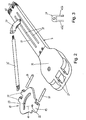
- shoulder joint orthosis 1 comprises a lower support element 2, which is applied laterally on the upper body in the hip area, and an upper contact element 3, which is applied directly below the shoulder on the side of the chest.
- Supporting element 2 and contact element 3 are fastened by means of a harness on the upper body, which includes straps 4 and a stable steel clip 5 in the illustrated embodiment.
- Support element 2 and contact element 3 are used for fastening a stable guide device 6, which comprises an elongated housing 7 and an extension rail 8 attached thereto.
- housing 7 and extension rail 8 made of metal, such as aluminum.
- the longitudinal axis of the housing 7 and the extension rail 8 extends substantially vertically, wherein the housing 7 is fixed to the upper contact element 3 and extends into the vicinity of the shoulder, ie, extends to near the armpit region of the patient, while the longitudinal rail 8 is fixed on the one hand to the lower end of the housing 7 and on the other hand to the lower section element 2 and the distance between the hip-near support element 2 and the upper contact element 3, depending on the length certainly.
- an upper arm splint 9 is articulated in the upper end region of the housing 7 by means of a hinge plate 10.
- this consists of two rail parts 9a, 9b, which are telescopically guided into each other and can be moved relative to each other to vary the Ausziehbone.
- the upper arm rail 9 is also pivotable relative to the hinge plate 10 about a pivot axis 11, so that the upper arm rail 9 can be fixed at different angles to the hinge plate 10.
- the hinge plate 10 arcuate slot 23 through which a screw, not shown, can be passed, with which the proximal rail part 9a is fixed to the hinge plate 10.
- the pivot axis 11 extends perpendicular to the pivot axis 12, about which the hinge plate 10 can be pivoted relative to the housing 7 in abduction and adduction.
- a half-shell-shaped upper arm support 13 is fixed, in which the upper arm can be inserted.
- the upper arm support 13 thus moves accordingly, so that the distance between upper arm support 13 and the orthotic joint can be changed.
- the humeral splint 9 is connected at its distal end to a lower arm splint 15 via a joint arranged under a cushion 14. On this a half-cupped forearm rest 16 is fixed, in which the forearm can be inserted. By means of a fastening strap 17, the forearm in the forearm rest 16 can be fixed.
- a hand rest 18 At the distal end of the forearm splint 15 is a hand rest 18, which in particular may be in the form of a crowned or spherical pad, which allows the patient to perform kneading exercises with his fingers.
- the hinge plate 10 forms a hinge joint with the guide device 6 and has for this purpose at one end a hinge flap 19 ( FIG. 2 ), which is pivotally connected via a hinge pin 20 with bearing webs 21 of the housing 7.
- a bore 22 is provided in the vicinity of the hinge plate 19, in which an unillustrated hinge pin is inserted.
- the humeral rail 9 is fixed to the hinge plate 10 in the proximal end region of the rail part 9a.
- a corresponding pivoting of the joint plate 10 in adduction and abduction direction is thus coupled with a corresponding pivoting of the humeral splint 9 and thus also the forearm splint 15.
- the hinge plate 10 further has at its opposite the hinge tab 19 end two hinge plates 24, which serve for the articulated connection of the upper end of a support rod 25.
- the support rod 25 is for this purpose introduced with the upper end between the joint plates 24 and fixed by means of a hinge pin 26.
- the upper arm splint 9 and thus the arm of the patient resting on it are held by means of the support rod 25 in desired Absp Dahlen relative to the upper body or exercises in corresponding Abdu irritations- and adduction movements on the hinge plate 10 and thus on the Oberarmschiene 9 from below a supporting force.
- the lower end of the support rod 25 engages via a fork-shaped coupling element 25 in two parallel longitudinal slots 28 of the housing 7 and can be moved against the action or with the assistance of a spring mechanism described in more detail below along the longitudinal slots 28.
- the spring force can be adjusted so that the support force acting on the humeral splint 9 just compensates for the weight of the patient's arm in each spreading position of the arm, so that the arm can be moved weightlessly, ie without significant active muscle support, in the abduction direction. Further, it is also possible to adjust the spring force so that the pushing force applied to the support rod 25 by the spring mechanism is larger than the weight of the arm including the arm splint, so that an active quenching treatment of the shoulder joint in the abduction direction is enabled. Furthermore, a fixation of the support rod 25 in any position of the shift range is possible, ie it is a stepless fixation of the humerus 9 and thus a static fixation of the arm in each Absp Dahl possible.
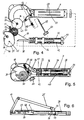
- the guide device 6 comprises the housing 7 and a gear 29, a spring 30 in the form of a spiral spring and a cam or eccentric disc 31 which are housed in a head portion 32 of the housing 7. On the cam 31, an end 33 of a cable 34 is fixed, the other end is fixed to a carriage 36.
- the carriage 36 is slidably disposed in an elongated housing portion 37, which adjoins the head portion 32.
- the guide of the carriage 36 via a centrally in the housing portion 37 stationarily arranged guide rod 38 which is guided through a corresponding longitudinal bore in the carriage 36 with little play.
- the displacement of the carriage 36 along the housing portion 37 is limited by stops 39, 40 which are formed as spindle nuts.
- Each stop 39, 40 is displaceable by its own spindle 41, 42 in the form of threaded rods, which are arranged parallel to each other on both sides of the guide rod 38 in the housing portion 37.
- the stop 39 is located on the side of the head 32 facing the Carriage 36, while the stopper 40 is located on the opposite side of the carriage 36.
- the stopper 39 thus limited in FIG. 5 the displacement of the carriage 30 to the left, ie in FIG. 1 upward, and thus the pivoting range of the humerus 9 in Abdu Vietnamesesraum.
- the stop 40 limits the displacement of the carriage 36 in FIG. 5 right, ie in FIG. 1 down, and thus the pivoting range of the humerus 9 in the adduction direction.
- the coupling element 27 is connected via a transverse bolt 44 (FIG. FIG. 6 ) hingedly connected to the carriage 36.
- the two side limbs 45a, 45b penetrate ( FIG. 3
- the displacement of the carriage 36 in the longitudinal direction of the housing 7 thus causes a corresponding displacement of the lower end of the support rod 25th
- the displacement of the carriage 36 takes place against or with the assistance of the spring force of the spring 30, depending on whether the humeral rail 9 is moved in the adduction direction or in the abduction direction.
- the spring 30 brings about the cam 31 and the cable 34 a permanent tensile force on the carriage 36 in the direction of the head part 32.
- cable guide roller 59 ensures that the cable 34 is introduced parallel to the direction of displacement of the carriage 36 in the housing portion 37.
- the biasing force of the spring 30 is adjusted via the gear 29.
- the gear 29 is about a transverse axis of rotation 46 (FIG. FIG. 4 ) rotatable by a in the head part 32 stored, not shown cross bolt is determined.
- the gear 29 carries a Strinvertechnikung 47, which cooperates with a worm wheel 48.
- the worm wheel 48 is rotatably connected to a shaft 49 which penetrates the worm wheel 48 in the longitudinal direction.
- the shaft 49 and thus the worm wheel 48 can be rotated via a sheet-shaped handling part 50, which is attached to the outer end of the shaft 49.
- the gear 29 is thus rotated corresponding to the axis of rotation 46. Due to the self-locking feature of the worm gear, the set rotational position of the gear 29 is maintained relative to the housing 7.
- FIG. 5 is also apparent that at the inside end of the shaft 49, a compression spring 51 is provided which in a recess 52 (FIG. FIG. 4 ) of the housing 7 is received.
- the inside end of the shaft 49 is in the in FIG. 5 shown actuating position only slightly into the compression spring 51 and is supported axially to the compression spring 51 out. This makes it possible to press the shaft 49 together with the handling part 50 when not in use axially against the pressure force of the compression spring 51 into the housing 7, so that the handling part 50 no longer projects beyond the housing 7.
- the worm wheel 48 mounted immovably in the head part 32 is axially displaceable, but non-rotatably mounted on a central polygonal section, for example a square section, of the shaft 49.
- the depressed position of the shaft 49 is by means of a retained latching mechanism, not shown.
- To actuate the shaft 49 of the locking mechanism is released, whereby the compression spring 51, the shaft 49 together with the handling part 50 in the in FIG. 5 shifts position shown.
- the gear 29 has a central, axially projecting square neck 53 and an adjoining cylindrical projection 54.
- the inner, also square-shaped bent end of the spring 30 is attached, which is rotatably connected to the gear 29 so.
- the cam 31 is attached, wherein the cylindrical projection 54 penetrates a bore 55 of the cam 31. The cam 31 is thus rotatable relative to the gear 29 about the axis of rotation 46.
- the cam 31 is coupled by means of a driving pin 56 which engages in an eyelet 57 at the outer end of the spring 30, with the spring 30.
- a driving pin 56 which engages in an eyelet 57 at the outer end of the spring 30, with the spring 30.
- the cam 31 is shaped in a special way, whereby a compensation mechanism is provided which counteracts the spring force variation such that the force applied to move the humerus 9 along the displacement path of the support rod 25 at least approximately remains the same.
- the rope 34 as from the FIGS. 9 and 10 can be seen, over a peripheral surface portion 48 of the cam 31 whose distance from the axis of rotation 46 of the cam 31 along the circumference of the cam 31 changes.
- the peripheral surface portion 48 with which the cable 34 depending on the rotational position of the cam 31 is more or less in contact, shown in dashed lines, since the cam 31 in this area has a guide groove in which the cable 34 is recessed.
- rotational position of the cam 31 corresponds to that which is taken at a maximum raised position of the humerus 9 and the hinge plate 10, as in FIG. 7 shown.
- This position corresponds for example to a 90 ° position relative to the housing 7.
- the support rod 25 in its highest position, wherein the spring 30 is maximally relaxed.
- the torque which is applied via the spring 30 on the cam 31 is thus relatively low due to the low spring force.
- FIG. 9 it can be seen, however, is also the effective lever arm l 1 between the axis of rotation 46 and that portion of the peripheral surface portion 48 is relatively short over which a train on the cable 34, a counter-rotating torque is applied to the cam 31.
- This short lever arm l 1 thus also causes a relatively low counter-torque on the cam 31 by acting on the humerus 9 weight force F ( FIG. 7 ).
- FIG. 8 the arm moves together with the hinge plate 10 and the support rod 25 down, and the slide 36 is moved downward and the cam 31 via the cable 34 in the clockwise direction in the FIG. 10 shown rotated position.
- the cable 34 thus remains in contact with an increasingly smaller portion of the peripheral surface portion 58, with the peripheral surface portion 58 progressively farther from the axis of rotation 46.
- maximum rotation of the cam 31 is the effective lever arm l 2 over which the cable 34 exerts a counter torque on the cam 31, longer than the effective lever arm l 1 of FIG.
- the curve of the peripheral surface portion 58 is formed so that the described compensation of the spring force variation by changing the effective lever lengths 11, 12 takes place in each angular position of the humerus 9.
- the upper arm can thus, if desired, be moved over the entire pivoting range in adduction and abduction direction weightless.
- the force with which the arm of a patient is supported can be changed continuously. With increasing healing, the spring force can thus be increasingly reduced, so that the patient has to burden the muscles required for abduction increasingly more. Conversely, the spring force can be increased so that the patient's arm is pushed upwardly by the humerus 9 to whip and widen the shoulder joint.
- the areas of application of the shoulder joint orthosis according to the invention are thus very diverse.
Description
Die Erfindung betrifft eine dynamische Schultergelenksorthese, insbesondere Schulterabduktionsorthese, gemäß dem Oberbegriff des Anspruches 1.The invention relates to a dynamic shoulder joint orthosis, in particular shoulder abduction orthosis, according to the preamble of
Das Schultergelenk des erwachsenen Menschen ist in ganz besonderem Maße gefährdet, bei nicht ausreichender Bewegung durch Kapselschrumpfung - besonders im Bereich des Recessus axillaris - und Verkleben der Verschiebestrukturen an Beweglichkeit zu verlieren und zwar vor allem im Sinne der Abspreizfähigkeit (Abduktion). Ein messbarer Immobilisierungsschaden einer ansonsten gesunden Schulter kann sich bereits nach einer Ruhigstellungsdauer von ca. einer Woche einstellen. Besonders gefährdet sind dabei Patienten im höheren Lebensalter. In Folge eines operativen Eingriffes mit einer Läsion der Kapselbandgewebe und der Gleitstrukturen ist das Risiko, eine Kontraktur des Schultergelenkes zu entwickeln, ungleich höher. Eine ausreichende Bewegung ist für die Funktion des Schultergelenkes jedoch extrem wichtig, um Kontrakturen zu vermeiden.The shoulder joint of the adult human being is particularly at risk of losing mobility if there is insufficient movement due to capsular shrinkage - especially in the area of the axillary recess - and sticking of the displacement structures, above all in terms of abduction capacity (abduction). A measurable immobilization damage of an otherwise healthy shoulder can already occur after a rest period of about one week. Particularly at risk are patients in later life. As a result of surgical intervention with a lesion of the capsular ligament tissue and the sliding structures, the risk of developing a contracture of the shoulder joint is much higher. Sufficient movement is extremely important for the function of the shoulder joint, in order to avoid contractures.
Sie fördert die Erguss- und Ödemresorption und hilft durch Beschleunigung des Blutflusses Thrombosen zu vermeiden.It promotes effusion and edema absorption and helps to prevent thrombosis by accelerating blood flow.
Bei einer relativ großen Anzahl von Patienten wird während oder nach einer operativen Behandlung einer Erkrankung oder einer Traumafolge der Schulter festgestellt, dass eine erhebliche Einschränkung der Stabilität der die Abduktion des Oberarmes bewirkenden Strukturen vorliegt. Dies ist zum Beispiel der Fall nach einer Refixation oder Rekonstruktion der Sehne des Musculus supraspinatus durch Naht, wieder Anheften am Tuberculum majus, Rekonstruktion durch einen Latissimus dorsi Transfer oder Refixation des Tuberculum majus oder bei Frakturen des proximalen Humerus, bei deren Versorgung mittels Platte, intermedullärem Nagel oder Endoprothese die Tubercula mit den anhängenden Sehnen der Rotatorenmanschette refixiert werden mussten.In a relatively large number of patients, during or after operative treatment of a disease or trauma of the shoulder, it is found that there is a significant reduction in the stability of abduction of the upper arm structures. This is the case, for example, after a refixation or reconstruction of the sinew of the supraspinatus muscle by suture, re-attachment to the greater tuberosity, reconstruction by a latissimus dorsi transfer or refixation of the greater tuberosity or fractures of the proximal humerus, when supplied by plate, intermedullar Nail or endoprosthesis the tubercles had to be refixed with the attached tendons of the rotator cuff.
In der Nachbehandlung ist es regelmäßig für eine relativ lange Zeit, beispielsweise sechs Wochen, erforderlich, die Rekonstruierten Strukturen vor einer erneuten Ruptur, bzw. Redislokation zu schützen. Der Arm wird daher üblicherweise mittels eines Abduktionskissens oder einer Abduktionsorthese in einer Abspreizstellung zwischen 30° bis 60° (abhängig vom intraoperativ festgestellten Spannungszustand der refixierten Sehnen) immobilisiert. Um die vorstehenden, durch nicht ausreichende Bewegung verursachten Probleme so gering wie möglich zu halten, erfolgt eine Übungsbehandlung durch passive Bewegungen der Schulter, zu deren Ausführung eine Hilfsperson erforderlich ist, beispielsweise ein Physiotherapeut oder entsprechend instruierte Angehörige. Die Nachbehandlung kann außerdem durch die Verwendung eines CPM-Stuhles (CPM: Continuous Passiv Motion) unterstützt werden. Hierbei wird der Arm auf eine Lagerungsschale eines speziellen Therapiestuhles gelegt und in einem definierbaren Umfang mittels Motorkraft passiv im Schultergelenk durchbewegt. Dieses Verfahren ist jedoch sehr kostenintensiv und aufwendig.In aftertreatment, it is usually necessary for a relatively long time, for example six weeks, to protect the reconstructed structures from rupture or redislocation. The arm is therefore usually immobilized by means of an abduction pad or an abduction orthosis in an abduction position between 30 ° to 60 ° (depending on the intraoperatively determined stress state of the refixed tendons). In order to minimize the above problems caused by insufficient movement, exercise is performed by passive movements of the shoulder, which requires an assistant, such as a physiotherapist or appropriately instructed relatives. Post-treatment may also be supported by the use of a CPM (Continuous Passive Motion) chair. This is The arm is placed on a storage tray of a special therapy chair and moved passively in a definable circumference by means of motor power in the shoulder joint. However, this method is very expensive and expensive.
Das passive Durchbewegen eines Schultergelenkes mit Hilfe eines Therapeuten ist jedoch wegen der zeitlichen Begrenzung nicht ausreichend geeignet, die im täglichen Gebrauch spontan ausgeführten Bewegungen zu ersetzen und einen Immobilisierungsschaden zuverlässig zu verhindern.The passive movement of a shoulder joint with the help of a therapist, however, is insufficient because of the time limit to replace the spontaneous movements in daily use and to reliably prevent immobilization damage.
Aus der
Eine weitere Orthese gemäß des Oberbegriffes von Anspruch 1 ist aus der
Mit Hilfe derartiger Orthesen ist es möglich, die Orthese durch Auswahl einer geeigneten Feder so einzustellen, dass sie den Oberarm in einer bestimmten Abduktionsstellung hält oder in diese Stellung zurück führt, ohne dass der Patient die entsprechenden Muskeln aktivieren müsste. Nachteilig ist jedoch, dass sich die Stützkraft der Orthese bei einer Schwenkbewegung des Oberarms ändert. Bei einer Bewegung in Adduktionsrichtung wird die Feder zunehmend zusammengedrückt, wodurch sich die Federkraft erhöht und eine immer weiter zunehmende Muskelkraft erforderlich ist, um den Oberarm nach unten in die maximal abgesenkte Stellung zu bewegen. Umgekehrt drückt die Feder die Oberarmschiene aus ihrer untersten Stellung zunächst mit sehr großer Federkraft in Abduktionsrichtung, während die Federkraft mit zunehmender Entspannung der Feder abnimmt. Die Federunterstützung variiert somit über den Federweg stark. Dies ist jedoch insbesondere in denjenigen Fällen, in denen es auf eine passive Mobilisierung des Schultergelenks und damit zusammenwirkender Sehnen und Muskeln ankommt, unerwünscht. Im Gegensatz zur Wirkung der bekannten Abduktionsorthese kann es auch häufig wünschenswert sein, die Stützkraft mit zunehmendem Abspreizwinkel des Oberarms sogar zu erhöhen, da dann die auf die Oberarmschiene drückende Gewichtskraft des Oberarms größer wird.With the help of such orthoses, it is possible to adjust the orthosis by selecting a suitable spring so that it holds the upper arm in a specific Abduktionsstellung or returns to this position, without the patient would have to activate the corresponding muscles. The disadvantage, however, is that the supporting force of the orthosis changes during a pivoting movement of the upper arm. In a movement in the adduction direction, the spring is increasingly compressed, which increases the spring force and an ever-increasing muscle power is required to move the upper arm down to the maximum lowered position. Conversely, the spring pushes the humeral splint from its lowest position initially with very high spring force in Abduktionsrichtung, while the spring force decreases with increasing relaxation of the spring. The spring support thus varies greatly over the travel. However, this is particularly undesirable in those cases where passive mobilization of the shoulder joint and associated tendons and muscles is required. In contrast to the effect of the known Abduktionsorthese it may also be desirable to even increase the support force with increasing Abspreizwinkel of the upper arm, because then the pressing on the humeral rail weight force of the upper arm is greater.
Der Erfindung liegt die Aufgabe zu Grunde, eine dynamische Schultergelenksorthese der eingangs genannten Art zu schaffen, mit der eine Mobilisierungsbehandlung der Schulter auf möglichst effektive und physiologisch optimale Weise möglich ist.The invention is based on the object to provide a dynamic shoulder joint orthosis of the type mentioned, with a mobilization treatment of the shoulder in the most effective and physiologically optimal way is possible.
Diese Aufgabe wird erfindungsgemäß durch eine dynamische Schultergelenksorthese mit den Merkmalen des Anspruches 1 gelöst. Vorteilhafte Ausführungsformen der Erfindung sind in den weiteren Ansprüchen beschrieben.This object is achieved by a dynamic shoulder joint orthosis with the features of
Bei der erfindungsgemäßen Schultergelenksorthese ist zwischen der Feder und der Stützstange ein Ausgleichsmechanismus vorgesehen, welcher der Federkraftveränderung entgegenwirkt, die beim Schwenken der Oberarmschiene auftritt, so dass die zum Schwenken der Oberarmschiene in Adduktionsrichtung und/oder Abduktionsrichtung aufzubringende Kraft über den gesamten Schwenkbereich zumindest annähernd gleich bleibt.In the shoulder joint orthosis according to the invention a compensation mechanism is provided between the spring and the support rod, which counteracts the spring force change, which occurs when the upper arm splint is pivoted, so that the force to be applied for pivoting the upper arm splint in the adduction direction and / or abduction direction remains at least approximately the same over the entire pivot range.
Die erfindungsgemäße Schultergelenksorthese ermöglicht eine sehr effektive Mobilisierungsbehandlung des Schultergelenks. Wird das Gelenk in dem vom Operateur als günstig eingestuften Bewegungsumfang freigegeben und die Federkraft so eingestellt, dass die Eigenschwere des darauf gelagerten Armes gerade überwunden wird, kann durch den Patienten insbesondere eine eigenständige, für die Adduktoren belastungsfreie Mobilisierung des Schultergelenkes ausgeführt werden. Insbesondere ist es möglich, dass durch eine bereits geringe Aktivierung der in der Regel nicht beeinträchtigen Adduktoren der Schulter (M. Latissimus dorsi, M. Pectoralis major, M. Subscapularis, M. Teres major und minor) der Arm im Schultergelenk bis zum definierten Ausgangspunkt (beispielsweise maximal 30°) adduziert und nach Entspannen der Adduktoren über die Federkraft bis zum definierten Endpunkt (in der Regel 90°) abduziert wird.The shoulder joint orthosis according to the invention enables a very effective mobilization treatment of the shoulder joint. If the joint is released in the range of motion classified as favorable by the surgeon and the spring force is adjusted so that the intrinsic severity of the arm supported thereon is just overcome, the patient can, in particular, carry out a separate mobilization of the shoulder joint stress-free for the adductors. In particular, it is possible that by an already low activation of the usually not impaired adductors of the shoulder (latissimus dorsi, pectoralis major, subscapularis, teres major and minor) the arm in the shoulder joint to the defined starting point (for example, a maximum of 30 °) adducted and after relaxation of the adductors via the spring force to the defined end point (usually 90 °) is abduziert.
Hierbei wird das "Kleinert-Prinzip" verwirklicht, d. h. bei der Aktivierung der Agonisten werden reflektorisch die Antagonisten entspannt. In diesem Fall werden bei Aktivierung der Adduktoren die Abduktoren entspannt und die Abduktion wird anschließend durch die Federkraft ausgeführt, so dass die schutzbedürftigen Strukturen bei der Bewegung des Schultergelenkes stets ohne Zugbelastung bleiben und nicht in ihrer Einheilung gestört werden.In this case, the "Kleinert principle" is realized, ie when activating the agonists, the antagonists are reflexively relaxed. In this case, when activating the adductor, the abductors are relaxed and the abduction is then carried out by the spring force, so that the structures requiring protection during movement of the shoulder joint always remain without tensile load and are not disturbed in their healing.
Von besonderem Vorteil ist, dass diese passive, für die Abduktoren der Schulter belastungsfreie Mobilisierung von Patienten jederzeit ohne weitere technische oder personelle Hilfen ausgeführt werden kann.It is of particular advantage that this passive, for the abductors of the shoulder load-free mobilization of patients at any time without further technical or personal help can be performed.
Liegt bereits eine Abspreizhemmung des Schultergelenkes (Abduktionskontraktur) durch eine Verklebung und Vernarbung des Recessus axilaris und der Sehnen vor, ist es möglich, durch eine entsprechende Einstellung der Federkraft deutlich über die Eigenschwere des Armes eine forcierte Abduktion zu bewirken. Hierdurch ist im Sinne einer Quengelungsbehandlung ein sukzessives Aufdehnen der Schulter und damit eine Steigerung des Bewegungsumfanges des Gelenkes erreichbar.If the shoulder joint (abduction contracture) is already blocked by an adhesion and scarring of the axillary recess and the tendons, it is possible to effect a forced abduction by a corresponding adjustment of the spring force significantly above the intrinsic severity of the arm. As a result, in the sense of a quenching treatment, a successive expansion of the shoulder and thus an increase in the range of motion of the joint can be achieved.
Gemäß einer vorteilhaften Ausführungsform umfasst der Ausgleichsmechanismus eine um eine Drehachse drehbare Kurvenscheibe, die mit einem mit dem unteren Ende der Stützstange in Wirkverbindung stehenden Kraftübertragungselement, vorzugsweise einem Seilzug, bewegungsgekoppelt ist, wobei zwischen Kraftübertragungselement und Drehachse der Kurvenscheibe ein Hebel wirkt, dessen Länge mit zunehmender Federkraft größer wird. Bei dieser Ausführungsform verändert sich somit in Abhängigkeit der Drehstellung der Kurvenscheibe die Länge des wirksamen Hebelarms, über den vom Kraftübertragungselement ein Drehmoment auf die Kurvenscheibe ausgeübt wird. Soll beispielsweise von der Feder eine konstante Kraft auf das untere Ende der Stützstange über den gesamten Verschiebeweg ausgeübt werden, kann die wirksame Hebellänge, über welche das Kraftübertragungselement auf die Kurvenscheibe ein Drehmoment ausübt, mit zunehmenden Drehwinkel der Kurvenscheibe und damit einhergehend mit zunehmender Federkraft zunehmend vergrößert werden, wodurch das vom Kraftübertragungselement auf die Kurvenscheibe ausgeübte Drehmoment in gleicher Weise vergrößert wird wie dasjenige Drehmoment, welches die Feder auf die Kurvenscheibe ausübt.According to an advantageous embodiment, the compensation mechanism comprises a cam rotatable about an axis of rotation, which is coupled to a force-transmitting element, preferably a cable, in operative connection with the lower end of the support rod, a lever acting between the force transmission element and the axis of rotation of the cam, the length of which increases with increasing Spring force is greater. In this embodiment, depending on the rotational position of the cam, the length of the effective lever arm, via which a torque is exerted on the cam by the force transmission element, thus changes. If, for example, the spring exerts a constant force on the lower end of the support rod over the entire displacement path, the effective lever length over which the force transmission element exerts a torque on the cam can be increasingly increased with increasing rotation angle of the cam and concomitantly with increasing spring force be, whereby the force exerted by the force transmission element on the cam torque is increased in the same manner as that torque which exerts the spring on the cam.
Selbstverständlich ist es auch möglich, den Ausgleichsmechanismus so einzustellen, dass die von der Feder auf das untere Ende der Stützstange übertragene Verschiebekraft nicht über den gesamten Verschiebeweg gleich bleibt, sondern sich gegebenenfalls an die momentan auf die Oberarmschiene wirkende, sich je nach Winkelstellung ändernde Gewichtskraft des Oberarms anpasst. Insbesondere ist es möglich, die von der Feder auf das untere Ende der Stützstange übertragene Verschiebekraft so einzustellen, dass sie an jeder Stelle des Verschiebewegs derjenigen Kraft entspricht, die notwendig ist, um in jeder Adduktions- bzw. Abduktionsstellung des Oberarms die Eigenschwere des Armes zu überwinden und so eine Bewegung des Arms ohne nennenswerte Beanspruchung der Muskeln zu ermöglichen.Of course, it is also possible to adjust the compensation mechanism so that the transmitted from the spring to the lower end of the support rod displacement force does not remain the same over the entire displacement, but possibly acting on the currently acting on the humeral rail, depending on the angular position changing weight of the Adjusts the upper arm. In particular, it is possible to adjust the displacement force transmitted by the spring to the lower end of the support rod so that at each point of the displacement it corresponds to the force necessary to increase the intrinsic weight of the arm in each adduction or abduction position of the upper arm overcome and allow a movement of the arm without significant stress on the muscles.
Gemäß einer vorteilhaften Ausführungsform umfasst das Kraftübertragungselement einen Seilzug, der über einen Umfangsflächenabschnitt der Kurvenscheibe geführt ist, wobei sich der Abstand des Umfangsflächenabschnitts zur Drehachse der Kurvenscheibe längs des Umfangs der Kurvenscheibe ändert. Dies ermöglicht eine einfache, platzsparende und sehr zuverlässig funktionierende Bauweise der Orthese.According to an advantageous embodiment, the force transmission element comprises a cable, which is guided over a peripheral surface portion of the cam, wherein the distance of the peripheral surface portion to the axis of rotation of the cam changes along the circumference of the cam. This allows a simple, space-saving and very reliable working construction of the orthosis.
Vorteilhafterweise besteht die Feder aus einer Spiralfeder, deren Hauptebene parallel zur Hauptebene der Kurvenscheibe angeordnet ist. Hierdurch lässt sich ebenfalls eine sehr platzsparende und einfache Bauweise verwirklichen.Advantageously, the spring consists of a spiral spring whose main plane is arranged parallel to the main plane of the cam. This also allows a very space-saving and simple construction realize.
Gemäß einer vorteilhaften Ausführungsform ist die Spiralfeder an einem Ende drehfest mit einem Zahnrad gekoppelt, das zur Einstellung der Vorspannkraft der Spiralfeder im Gehäuse der Führungseinrichtung drehbar gelagert ist. Auf diese Weise kann die Vorspannkraft der Feder auf sehr einfache Weise verändert und an die jeweiligen Bedürfnisse angepasst werden, ohne die Feder wechseln zu müssen.According to an advantageous embodiment, the coil spring is rotatably coupled at one end with a gear which is rotatably mounted for adjusting the biasing force of the spiral spring in the housing of the guide means. In this way, the biasing force of the spring can be changed in a very simple manner and adapted to the particular needs, without having to change the spring.
Vorteilhafterweise ist das Zahnrad mittels eines Schneckenrads drehbar, das über einen manuell betätigbaren Drehmechanismus drehbar ist. Hierdurch kann ein selbsthemmendes Getriebe zwischen Schneckenrad und Zahnrad geschaffen werden, das ohne weitere Blockierelemente die eingestellte Lage des Zahnrads aufrecht erhält.Advantageously, the gear is rotatable by means of a worm wheel which is rotatable via a manually operable rotating mechanism. In this way, a self-locking gear between worm and gear can be created, which maintains the set position of the gear without further blocking elements.
Eine sehr präzise arbeitende Orthese und genaue Führung der Stützstange ergibt sich, wenn im Gehäuse der Führungseinrichtung ein Schlitten längs verschiebbar geführt ist, an dem das untere Ende der Stützstange angelenkt und an dem der Seilzug befestigt ist, so dass der Schlitten bei einer Abduktions- oder Adduktionsbewegung der Oberarmschiene sowohl mit der Oberarmschiene als auch mit der federbelasteten Kurvenscheibe bewegungsgekoppelt ist.A very precise working orthosis and precise guidance of the support rod is obtained when a slide is guided longitudinally displaceable in the housing of the guide device, to which the lower end of the support rod articulated and to which the cable is attached, so that the carriage at an abduction or Adduction movement of the humeral splint is motion coupled with both the humeral rail and with the spring-loaded cam.
Vorteilhafterweise wird der Schwenkbereich der Oberarmschiene durch einen Schlittenwegbegrenzungsmechanismus begrenzt, der in oder am Gehäuse angeordnete, in Längsrichtung des Schlittenwegs verstellbare Anschläge aufweist. Zweckmäßigerweise umfasst hierzu der Schlittenwegbegrenzungsmechanismus zwei parallel im Gehäuse angeordnete Spindeln, die jeweils einen Anschlag in der Form einer Spindelmutter tragen. Hierdurch kann auf einfache Weise durch Drehen einer entsprechenden Spindel der zugeordnete Anschlag verstellt werden, um den Schwenkbereich der Oberarmschiene entsprechend zu verändern.Advantageously, the pivoting range of the upper arm rail is limited by a Schlittenwegbegrenzungsmechanismus having arranged in or on the housing, adjustable in the longitudinal direction of the carriage travel stops. Appropriately, this includes the Schlittenwegbegrenzungsmechanismus two parallel arranged in the housing spindles, each carrying a stop in the form of a spindle nut. As a result, in a simple manner by rotating a corresponding spindle of the associated Stops are adjusted to change the swing range of the humeral rail accordingly.
Die Erfindung wird nachfolgend anhand der Zeichnungen beispielhaft näher erläutert. Es zeigen:
- Figur 1:
- eine Schultergelenksorthese gemäß der Erfindung in räumlicher Darstellung,
- Figur 2:
- eine Explosionsdarstellung der Führungseinrichtung, Stützstange, Gelenkplatte und des Stützstangen-Kupplungsteils,
- Figur 3:
- eine Vorderansicht des Kupplungsteils von
Figur 2 - Figur 4:
- wesentliche Einzelteile der Führungseinrichtung,
- Figur 5:
- die
Einzelteile von Figur 4 im montierten Zustand, - Figur 6:
- einen Längsschnitt durch die
Führungseinrichtung von Figur 5 , - Figur 7:
- eine Seitenansicht der Führungseinrichtung, wobei sich Stützstange und Gelenkplatte in einer ersten, angehobenen Stellung befinden,
- Figur 8:
- eine
Darstellung gemäß Figur 7 , wobei sich Stützstange und Gelenkplatte in einer zweiten, abgesenkten Stellung befinden, - Figur 9:
- die Kurvenscheibe und den Seilzug in einer Drehstellung der Kurvenscheibe, die sie bei einer Stellung der Orthese gemäß
Figur 7 einnimmt, - Figur 10:
- die Kurvenscheibe und den Seilzug, wenn sich die Orthese in der
Stellung von Figur 8 befindet, - Figur 11:
- eine Vorderansicht auf das Zahnrad der Führungseinrichtung, und
- Figur 12:
- eine Seitenansicht auf das
Zahnrad von Figur 11 .
- FIG. 1:
- a shoulder joint orthosis according to the invention in a spatial representation,
- FIG. 2:
- an exploded view of the guide means, support rod, hinge plate and the support rod coupling part,
- FIG. 3:
- a front view of the coupling part of
FIG. 2 . - FIG. 4:
- essential parts of the management device,
- FIG. 5:
- the items of
FIG. 4 in the assembled state, - FIG. 6:
- a longitudinal section through the guide device of
FIG. 5 . - FIG. 7:
- a side view of the guide device, wherein support rod and hinge plate are in a first, raised position,
- FIG. 8:
- a representation according to
FIG. 7 , wherein the support rod and hinge plate are in a second, lowered position, - FIG. 9:
- the cam and the cable in a rotational position of the cam, they in accordance with a position of the orthosis
FIG. 7 occupies - FIG. 10:
- the cam and the cable when the orthosis is in the position of
FIG. 8 is, - FIG. 11:
- a front view of the gear of the guide device, and
- FIG. 12:
- a side view of the gear of
FIG. 11 ,
Die in
Abstützelement 2 und Anlageelement 3 dienen zur Befestigung einer stabilen Führungseinrichtung 6, die ein längliches Gehäuse 7 und eine daran befestigte Verlängerungsschiene 8 umfasst. Zweckmäßigerweise bestehen Gehäuse 7 und Verlängerungsschiene 8 aus Metall, beispielsweise Aluminium. Im angelegten Zustand der Schultergelenksorthese 1 verläuft die Längsachse des Gehäuses 7 und der Verlängerungsschiene 8 im Wesentlichen vertikal, wobei das Gehäuse 7 am oberen Anlageelement 3 befestigt ist und sich bis in die Nähe der Schulter, d.h. bis nahe zum Achselbereich des Patienten, erstreckt, während die Längsschiene 8 einerseits am unteren Ende des Gehäuses 7 und andererseits am unteren Abschnittselement 2 befestigt ist und je nach Länge den Abstand zwischen dem hüftnahen Abstützelement 2 und dem oberen Anlageelement 3 bestimmt.
Um den Arm eines Patienten in abgespreizter Stellung zu halten und/oder in Abduktions- und Adduktionsrichtung unterstützend zu führen, ist eine Oberarmschiene 9 mittels einer Gelenkplatte 10 gelenkig im oberen Endbereich des Gehäuses 7 gelagert. Zur Längenverstellung der Oberarmschiene 9 besteht diese aus zwei Schienenteilen 9a, 9b, die teleskopartig ineinander geführt sind und relativ zueinander verschoben werden können, um die Ausziehlänge zu variieren. Die Oberarmschiene 9 ist dabei endseitig relativ zur Gelenkplatte 10 auch um eine Schwenkachse 11 schwenkbar, so dass die Oberarmschiene 9 in unterschiedlichen Winkeln an der Gelenkplatte 10 fixiert werden kann. Hierzu dient ein in der Gelenkplatte 10 vorgesehenes kreisbogenförmiges Langloch 23, durch das eine nicht dargestellte Schraube hindurchgeführt werden kann, mit der das proximale Schienenteil 9a an der Gelenkplatte 10 festgelegt wird. Die Schwenkachse 11 verläuft senkrecht zur Schwenkachse 12, um welche die Gelenkplatte 10 relativ zum Gehäuse 7 in Abduktions- und Adduktionsrichtung verschwenkt werden kann.In order to hold the arm of a patient in a splayed position and / or to assist in the abduction and adduction direction, an upper arm splint 9 is articulated in the upper end region of the
An der Oberseite des Schienenteils 9b ist eine halbschalenförmige Oberarmauflage 13 befestigt, in die der Oberarm eingelegt werden kann. Bei einem Verschieben des distalen Schienenteils 9b relativ zum proximalen Schienenteil 9a bewegt sich somit die Oberarmauflage 13 entsprechend mit, so dass der Abstand zwischen Oberarmauflage 13 und dem Orthesengelenk verändert werden kann.At the top of the rail part 9b, a half-shell-shaped
Die Oberarmschiene 9 ist an ihrem distalen Ende über ein unter einem Kissen 14 angeordneten Gelenk mit einer Unterarmschiene 15 verbunden. Auf dieser ist eine halbschalenförmige Unterarmauflage 16 befestigt, in die der Unterarm eingelegt werden kann. Mittels eines Befestigungsbandes 17 kann der Unterarm in der Unterarmauflage 16 fixiert werden. Am distalen Ende der Unterarmschiene 15 befindet sich eine Handauflage 18, die insbesondere die Form eines balligen oder kugeligen Kissens haben kann, das es dem Patienten ermöglicht, mit seinen Fingern Knetübungen durchzuführen.The humeral splint 9 is connected at its distal end to a
Die Gelenkplatte 10 bildet ein Scharniergelenk mit der Führungseinrichtung 6 und weist hierzu an einem Ende eine Gelenklasche 19 auf (
Die Oberarmschiene 9 ist im proximalen Endbereich des Schienenteils 9a an der Gelenkplatte 10 fixiert. Ein entsprechendes Verschwenken der Gelenkplatte 10 in Adduktions- und Abduktionsrichtung ist somit mit einem entsprechenden Verschwenken der Oberarmschiene 9 und damit auch der Unterarmschiene 15 gekoppelt.The humeral rail 9 is fixed to the
Die Gelenkplatte 10 weist weiterhin an ihrem der Gelenklasche 19 gegenüberliegenden Ende zwei Gelenklaschen 24 auf, die zum gelenkigen Verbinden des oberen Endes einer Stützstange 25 dienen. Die Stützstange 25 ist hierzu mit dem oberen Ende zwischen die Gelenklaschen 24 eingeführt und mittels eines Gelenkstifts 26 festgelegt.The
Die Oberarmschiene 9 und damit der darauf aufliegende Arm des Patienten wird mittels der Stützstange 25 in gewünschten Abspreizstellungen relativ zum Oberkörper gehalten oder übt bei entsprechenden Abduktions- und Adduktionsbewegungen auf die Gelenkplatte 10 und damit auf die Oberarmschiene 9 von unten her eine Stützkraft aus. Das untere Ende der Stützstange 25 greift über ein gabelförmiges Kupplungselement 25 in zwei parallele Längsschlitze 28 des Gehäuses 7 ein und kann gegen die Wirkung oder mit Unterstützung eines nachfolgend noch näher beschriebenen Federmechanismus entlang der Längsschlitze 28 verschoben werden. Die Federkraft kann dabei so eingestellt werden, dass die auf die Oberarmschiene 9 wirkende Stützkraft das Gewicht des Arms des Patienten in jeder Abspreizstelllung des Arm gerade kompensiert, so dass der Arm schwerelos, d. h. ohne nennenswerte aktive Muskelunterstützung, in Abduktionsrichtung bewegt werden kann. Weiterhin ist es auch möglich, die Federkraft so einzustellen, dass die durch den Federmechanismus aufgebrachte, auf die Stützstange 25 einwirkende Schiebekraft größer als die Gewichtskraft des Arms einschließlich der Armschiene ist, so dass eine aktive Quengelungsbehandlung des Schultergelenks in Abduktionsrichtung ermöglicht wird. Ferner ist eine Fixierung der Stützstange 25 in jeder beliebigen Lage des Verschiebebereichs möglich, d.h. es ist eine stufenlose Fixierung der Oberarmschiene 9 und damit eine statische Fixierung des Arms in jeder Abspreizstellung möglich.The upper arm splint 9 and thus the arm of the patient resting on it are held by means of the
Im Folgenden wird anhand der
Die Führungseinrichtung 6 umfasst das Gehäuse 7 sowie ein Zahnrad 29, eine Feder 30 in der Form einer Spiralfeder und eine Kurven- oder Exzenterscheibe 31, die in einem Kopfteil 32 des Gehäuses 7 untergebracht sind. An der Kurvenscheibe 31 ist ein Ende 33 eines Seils 34 befestigt, dessen anderes Ende an einem Schlitten 36 befestigt ist.The guide device 6 comprises the
Der Schlitten 36 ist in einem länglichen Gehäuseabschnitt 37 verschiebbar angeordnet, der sich an das Kopfteil 32 anschließt. Die Führung des Schlittens 36 erfolgt über einen mittig im Gehäuseabschnitt 37 stationär angeordneten Führungsstab 38, der durch eine entsprechende Längsbohrung im Schlitten 36 mit geringem Spiel hindurch geführt ist. Der Verschiebebereich des Schlitten 36 längs des Gehäuseabschnitts 37 wird durch Anschläge 39, 40 begrenzt, die als Spindelmuttern ausgebildet sind. Jeder Anschlag 39, 40 ist durch eine eigene Spindel 41, 42 in der Form von Gewindestäben verschiebbar, die parallel zueinander beidseits des Führungsstabs 38 im Gehäuseabschnitt 37 angeordnet sind. Da die Anschläge 39, 40 drehfest im Gehäuse 7 angeordnet sind, bewirkt ein Drehen der Spindeln 41, 42 ein Verschieben der Anschläge 39, 40 in Längsrichtung des Gehäuses 7. Das Drehen der Spindeln 41, 42 erfolgt über drehfest verbundene Rändelscheiben 43, die am Ende des Führungsabschnitt 37 über das Gehäuse 7 vorstehen (siehe auch
Im gezeigten Ausführungsbeispiel befindet sich der Anschlag 39 auf der dem Kopfteil 32 zugewandten Seite des Schlittens 36, während sich der Anschlag 40 auf der gegenüberliegenden Seite des Schlittens 36 befindet. Der Anschlag 39 begrenzt somit in
Das Kupplungselement 27 ist über einen Querbolzen 44 (
Die Verschiebung des Schlittens 36 erfolgt gegen die bzw. mit Unterstützung der Federkraft der Feder 30, je nachdem, ob die Oberarmschiene 9 in Adduktionsrichtung oder in Abduktionsrichtung bewegt wird. Hierzu bringt die Feder 30 über die Kurvenscheibe 31 und das Seil 34 eine permanente Zugkraft auf den Schlitten 36 in Richtung Kopfteil 32 auf. Eine aus den
Die Vorspannkraft der Feder 30 wird über das Zahnrad 29 eingestellt. Das Zahnrad 29 ist um eine querverlaufende Drehachse 46 (
Aus
Damit diese Verschiebung erfolgen kann, ist das unverschiebbar im Kopfteil 32 gelagerte Schneckenrad 48 axial verschiebbar, jedoch drehfest auf einem mittigen Mehrkantabschnitt, beispielsweise Vierkantabschnitt, der Welle 49 gelagert.For this shift to take place, the
Die eingedrückte Stellung der Welle 49 wird mittels eines nicht dargestellten Rastmechanismus beibehalten. Zur Betätigung der Welle 49 wird der Rastmechanismus gelöst, wodurch die Druckfeder 51 die Welle 49 zusammen mit dem Handhabungsteil 50 in die in
Wie aus den
Die Kurvenscheibe 31 ist mittels eines Mitnahmebolzens 56, der in eine Öse 57 am äußeren Ende der Feder 30 eingreift, mit der Feder 30 gekoppelt. Durch die Vorspannkraft der Feder 30 wird damit ein Drehmoment auf die Kurvenscheibe 31 um die Drehachse 46 ausgeübt, das in dem in den
Es ist erkennbar, dass eine Abduktionsbewegung des Arms durch die Kraft unterstützt wird, mit der der Schlitten 36 mittels des Federmechanismus nach oben gezogen wird, während bei einer Adduktionsbewegung des Arms die Federkraft als Bremskraft wirkt, da der Schlitten 36 entgegen der Federkraft nach unten verschoben wird.It can be seen that an abduction movement of the arm is supported by the force with which the
Bei einer Adduktionsbewegung des Arms, würde normalerweise die Federkraft mit zunehmendem Verschiebeweg des Schlittens 36 zunehmen, da sich die Feder 30 zunehmend verformt. Umgekehrt würde bei einer Abduktionsbewegung des Arms die Federunterstützung bei zunehmender Entspannung der Feder 30 abnehmen. Um diese unerwünschten Effekte zu vermeiden, ist die Kurvenscheibe 31 in spezieller Weise geformt, wodurch ein Ausgleichsmechanismus geschaffen wird, welcher der Federkraftveränderung derart entgegenwirkt, dass die zum Bewegen der Oberarmschiene 9 aufzubringende Kraft längs des Verschiebewegs der Stützstange 25 zumindest annähernd gleich bleibt. Hierzu verläuft das Seil 34, wie aus den
Die in
Wie aus
wird nun, wie aus
Der Kurvenverlauf des Umfangsflächenabschnitts 58 ist so ausgebildet, dass die beschriebene Kompensation der Federkraftveränderung durch Veränderung der wirksamen Hebellängen 11, 12, in jeder Winkelstellung der Oberarmschiene 9 stattfindet. Der Oberarm kann damit, falls gewünscht, über den gesamten Schwenkbereich in Adduktions- und Abduktionsrichtung schwerelos bewegt werden.The curve of the
Durch Veränderung der Vorspannkraft der Feder 30 durch Drehen des Zahnrads 29 kann die Kraft, mit der der Arm eines Patienten unterstützt wird, stufenlos verändert werden. Mit zunehmender Heilung kann die Federkraft somit auch zunehmend verringert werden, so dass der Patient die zur Abduktion erforderlichen Muskeln zunehmend mehr belasten muss. Umgekehrt kann die Federkraft so erhöht werden, dass der Arm des Patienten durch die Oberarmschiene 9 nach oben gedrückt wird, um das Schultergelenkt zu quengeln und aufzuweiten. Die Einsatzbereiche der erfindungsgemäßen Schultergelenksorthese sind damit sehr vielfältig.By changing the biasing force of the
Claims (10)
- Dynamic shoulder joint orthesis, in particular a shoulder abduction orthesis, comprising:- a guide means (6) which can be fastened on the upper body and comprises a housing (7),- an upper arm splint (9) which is fastened in an articulated manner to the guide means (6) and can be moved at least in the adduction and abduction directions,- a support rod (25) for supporting the upper arm splint (9), the support rod (25) comprising a lower end which is guided displaceably on the guide means (6),- a spring (30) for applying a displacement force on the lower end of the support rod (25).characterised in that a compensation mechanism is provided between the spring (30) and the support rod (25) and counteracts a change in spring force which occurs when the upper arm splint (9) is pivoted, such that the force to be applied to pivot the upper arm splint (9) in the adduction direction and/or in the abduction direction remains at least approximately the same over the entire pivoting range.
- Shoulder joint orthesis according to claim 1, characterised in that the compensation mechanism comprises a cam (31) which is rotatable about an axis of rotation (46) and can be coupled in motion to a force transfer element cooperating with the lower end of the support rod (25), a lever arm acting between the force transfer element and the axis of rotation (46) of the cam (31), the length 11, 12 of which lever becomes greater with increasing spring force.
- Shoulder joint orthesis according to claim 2, characterised in that the force transfer element comprises a Bowden cable which is guided over a peripheral surface portion (58) of the cam (31), the distance between the peripheral surface portion (58) and the axis of rotation (46) of the cam (31) changing along the periphery of the cam (31).
- Shoulder joint orthesis according to either claim 2 or claim 3, characterised in that the spring (30) consists of a spiral spring which is arranged in terms of the primary plane parallel to the primary plane of the cam (31).
- Shoulder joint orthesis according to claim 4, characterised in that the spiral spring is coupled at one end to a gearwheel (29) in a rotationally engaged manner, which gearwheel is mounted rotatably in the housing (7) of the guide means (6) to adjust the biasing force of the spiral spring.
- Shoulder joint orthesis according to claim 5, characterised in that the gearwheel (29) and the cam (31) are arranged parallel to one another and are rotatable about the same axis of rotation (46).
- Shoulder joint orthesis according to either claim 5 or claim 6, characterised in that the gearwheel (29) is rotatable by means of a worm wheel (48) which is rotatable by a manually actuatable rotation mechanism.
- Shoulder joint orthesis according to any one of claims 3 to 7, characterised in that a sliding carriage (36) is guided in the housing (7) of the guide means (6) in a longitudinally displaceable manner, to which sliding carriage the lower end of the support rod (25) is articulated and to which the Bowden cable is fastened in such a way that the sliding carriage (36) is coupled in motion both with the upper arm splint (9) and with the spring-loaded cam (31) during an abduction or adduction movement of the upper arm splint (9).
- Shoulder joint orthesis according to claim 8, characterised in that the pivoting range of the upper arm splint (9) is defined by a sliding carriage path delimitation mechanism which comprises stops (39, 40) which are arranged in or on the housing (7) and are adjustable in the longitudinal direction of the sliding carriage path.
- Shoulder joint orthesis according to claim 9, characterised in that the sliding carriage path delimitation mechanism comprises two spindles (41, 42) which are arranged in parallel in the housing (7) and which each bear a stop (39, 40) in the form of a spindle nut.
Applications Claiming Priority (1)
| Application Number | Priority Date | Filing Date | Title |
|---|---|---|---|
| DE102010049189A DE102010049189B4 (en) | 2010-10-21 | 2010-10-21 | Dynamic shoulder joint orthosis, especially shoulder abduction orthosis |
Publications (2)
| Publication Number | Publication Date |
|---|---|
| EP2444037A1 EP2444037A1 (en) | 2012-04-25 |
| EP2444037B1 true EP2444037B1 (en) | 2012-12-12 |
Family
ID=44719085
Family Applications (1)
| Application Number | Title | Priority Date | Filing Date |
|---|---|---|---|
| EP11007733A Not-in-force EP2444037B1 (en) | 2010-10-21 | 2011-09-22 | Dynamic shoulder joint orthotic, in particular shoulder abduction orthotic |
Country Status (3)
| Country | Link |
|---|---|
| US (1) | US20120101420A1 (en) |
| EP (1) | EP2444037B1 (en) |
| DE (1) | DE102010049189B4 (en) |
Families Citing this family (5)
| Publication number | Priority date | Publication date | Assignee | Title |
|---|---|---|---|---|
| SE535730C2 (en) * | 2011-02-04 | 2012-11-27 | Stig Malmqvist | Device for physical exercise |
| EP2811946B1 (en) | 2012-02-07 | 2019-01-02 | S.A.M. Bracing Pty Ltd | Joint for rehabilitation device |
| WO2016160661A1 (en) | 2015-03-27 | 2016-10-06 | Ossur Iceland Ehf | Orthopedic device for scapulothoracic stabilization |
| ES2609509B1 (en) * | 2015-10-15 | 2018-06-25 | Regina TOLOSA ECHEPARE | MUSCLE ANTI FATIGUE DEVICE |
| CN108309537B (en) * | 2018-03-29 | 2023-07-21 | 北京大学第三医院 | Shoulder joint brace and manufacturing method thereof |
Family Cites Families (2)
| Publication number | Priority date | Publication date | Assignee | Title |
|---|---|---|---|---|
| DE8407242U1 (en) * | 1984-06-07 | Otto Bock Orthopädische Industrie Besitz- und Verwaltungs-KG, 3428 Duderstadt | Dynamic shoulder abduction orthosis | |
| US2661000A (en) * | 1951-06-25 | 1953-12-01 | William E Gazeley | Surgical splint |
-
2010
- 2010-10-21 DE DE102010049189A patent/DE102010049189B4/en not_active Expired - Fee Related
-
2011
- 2011-09-22 EP EP11007733A patent/EP2444037B1/en not_active Not-in-force
- 2011-10-12 US US13/271,269 patent/US20120101420A1/en not_active Abandoned
Also Published As
| Publication number | Publication date |
|---|---|
| DE102010049189B4 (en) | 2012-07-19 |
| US20120101420A1 (en) | 2012-04-26 |
| EP2444037A1 (en) | 2012-04-25 |
| DE102010049189A1 (en) | 2012-04-26 |
Similar Documents
| Publication | Publication Date | Title |
|---|---|---|
| EP2444035B1 (en) | Dynamic shoulder joint orthotic, in particular shoulder abduction orthotic, with floating upper arm rail part | |
| DE112012004113B4 (en) | Orthosis for the correction of upper arm fractures | |
| DE2528583B2 (en) | Device for the surgical treatment of bones and joints | |
| EP1568337A1 (en) | Orthosis for the correction of the position of an anatomical joint | |
| EP0841044A1 (en) | Dynamic brace | |
| EP2444037B1 (en) | Dynamic shoulder joint orthotic, in particular shoulder abduction orthotic | |
| WO2004056293A1 (en) | Device for applying a ventrally or dorsally directed translatory force in the area of a knee joint | |
| EP3037075A2 (en) | Orthosis with inclination adjustment device | |
| EP4057954B1 (en) | Orthopaedic device for supporting a user's lower back | |
| WO2021094159A1 (en) | Device for supporting the back of a user | |
| EP3281610B1 (en) | Orthosis | |
| WO2023025354A1 (en) | Adjustable orthosis joint for the controlled movement and/or fixation of a hand, and orthosis having an orthosis joint of this kind | |
| DE102008049854B4 (en) | Orthosis for correcting malpositions and redressing of limbs in the abduction or adduction direction | |
| DE102015005572B4 (en) | Knee orthosis for applying a ventrally or dorsally directed translational force | |
| EP2799039B1 (en) | Orthotic | |
| EP3871640A1 (en) | Orthosis for thumb saddle joint | |
| DE102021002999A1 (en) | Orthopedic device for generating forces dependent on the angle of movement | |
| DE102015012320B4 (en) | Wrist brace | |
| EP4057952A1 (en) | Orthopaedic device | |
| DE102017213300B3 (en) | Orthotic joint splint with actively moving pad and joint orthosis | |
| DE69737893T2 (en) | DEVICE FOR THE PHYSICAL THERAPY OF SHOULDERS | |
| DE19731358C2 (en) | Exercise device, in particular for self-mobilization of body joints, especially shoulder joints | |
| DE102015008031B4 (en) | Knee orthosis for applying a forward or backward translational force | |
| DE202010014505U1 (en) | joint orthosis |
Legal Events
| Date | Code | Title | Description |
|---|---|---|---|
| AK | Designated contracting states |
Kind code of ref document: A1 Designated state(s): AL AT BE BG CH CY CZ DE DK EE ES FI FR GB GR HR HU IE IS IT LI LT LU LV MC MK MT NL NO PL PT RO RS SE SI SK SM TR |
|
| AX | Request for extension of the european patent |
Extension state: BA ME |
|
| PUAI | Public reference made under article 153(3) epc to a published international application that has entered the european phase |
Free format text: ORIGINAL CODE: 0009012 |
|
| 17P | Request for examination filed |
Effective date: 20120405 |
|
| RIC1 | Information provided on ipc code assigned before grant |
Ipc: A61F 5/37 20060101AFI20120615BHEP |
|
| GRAP | Despatch of communication of intention to grant a patent |
Free format text: ORIGINAL CODE: EPIDOSNIGR1 |
|
| GRAS | Grant fee paid |
Free format text: ORIGINAL CODE: EPIDOSNIGR3 |
|
| GRAA | (expected) grant |
Free format text: ORIGINAL CODE: 0009210 |
|
| AK | Designated contracting states |
Kind code of ref document: B1 Designated state(s): AL AT BE BG CH CY CZ DE DK EE ES FI FR GB GR HR HU IE IS IT LI LT LU LV MC MK MT NL NO PL PT RO RS SE SI SK SM TR |
|
| REG | Reference to a national code |
Ref country code: GB Ref legal event code: FG4D Free format text: NOT ENGLISH |
|
| REG | Reference to a national code |
Ref country code: CH Ref legal event code: EP |
|
| REG | Reference to a national code |
Ref country code: AT Ref legal event code: REF Ref document number: 587972 Country of ref document: AT Kind code of ref document: T Effective date: 20121215 |
|
| REG | Reference to a national code |
Ref country code: IE Ref legal event code: FG4D Free format text: LANGUAGE OF EP DOCUMENT: GERMAN |
|
| REG | Reference to a national code |
Ref country code: DE Ref legal event code: R096 Ref document number: 502011000260 Country of ref document: DE Effective date: 20130207 |
|
| PG25 | Lapsed in a contracting state [announced via postgrant information from national office to epo] |
Ref country code: NO Free format text: LAPSE BECAUSE OF FAILURE TO SUBMIT A TRANSLATION OF THE DESCRIPTION OR TO PAY THE FEE WITHIN THE PRESCRIBED TIME-LIMIT Effective date: 20130312 Ref country code: HR Free format text: LAPSE BECAUSE OF FAILURE TO SUBMIT A TRANSLATION OF THE DESCRIPTION OR TO PAY THE FEE WITHIN THE PRESCRIBED TIME-LIMIT Effective date: 20121212 Ref country code: ES Free format text: LAPSE BECAUSE OF FAILURE TO SUBMIT A TRANSLATION OF THE DESCRIPTION OR TO PAY THE FEE WITHIN THE PRESCRIBED TIME-LIMIT Effective date: 20130323 Ref country code: LT Free format text: LAPSE BECAUSE OF FAILURE TO SUBMIT A TRANSLATION OF THE DESCRIPTION OR TO PAY THE FEE WITHIN THE PRESCRIBED TIME-LIMIT Effective date: 20121212 Ref country code: FI Free format text: LAPSE BECAUSE OF FAILURE TO SUBMIT A TRANSLATION OF THE DESCRIPTION OR TO PAY THE FEE WITHIN THE PRESCRIBED TIME-LIMIT Effective date: 20121212 Ref country code: SE Free format text: LAPSE BECAUSE OF FAILURE TO SUBMIT A TRANSLATION OF THE DESCRIPTION OR TO PAY THE FEE WITHIN THE PRESCRIBED TIME-LIMIT Effective date: 20121212 |
|
| REG | Reference to a national code |
Ref country code: NL Ref legal event code: VDEP Effective date: 20121212 |
|
| REG | Reference to a national code |
Ref country code: LT Ref legal event code: MG4D |
|
| PG25 | Lapsed in a contracting state [announced via postgrant information from national office to epo] |
Ref country code: GR Free format text: LAPSE BECAUSE OF FAILURE TO SUBMIT A TRANSLATION OF THE DESCRIPTION OR TO PAY THE FEE WITHIN THE PRESCRIBED TIME-LIMIT Effective date: 20130313 Ref country code: LV Free format text: LAPSE BECAUSE OF FAILURE TO SUBMIT A TRANSLATION OF THE DESCRIPTION OR TO PAY THE FEE WITHIN THE PRESCRIBED TIME-LIMIT Effective date: 20121212 Ref country code: SI Free format text: LAPSE BECAUSE OF FAILURE TO SUBMIT A TRANSLATION OF THE DESCRIPTION OR TO PAY THE FEE WITHIN THE PRESCRIBED TIME-LIMIT Effective date: 20121212 |
|
| PG25 | Lapsed in a contracting state [announced via postgrant information from national office to epo] |
Ref country code: SK Free format text: LAPSE BECAUSE OF FAILURE TO SUBMIT A TRANSLATION OF THE DESCRIPTION OR TO PAY THE FEE WITHIN THE PRESCRIBED TIME-LIMIT Effective date: 20121212 Ref country code: CZ Free format text: LAPSE BECAUSE OF FAILURE TO SUBMIT A TRANSLATION OF THE DESCRIPTION OR TO PAY THE FEE WITHIN THE PRESCRIBED TIME-LIMIT Effective date: 20121212 Ref country code: RS Free format text: LAPSE BECAUSE OF FAILURE TO SUBMIT A TRANSLATION OF THE DESCRIPTION OR TO PAY THE FEE WITHIN THE PRESCRIBED TIME-LIMIT Effective date: 20121212 Ref country code: EE Free format text: LAPSE BECAUSE OF FAILURE TO SUBMIT A TRANSLATION OF THE DESCRIPTION OR TO PAY THE FEE WITHIN THE PRESCRIBED TIME-LIMIT Effective date: 20121212 Ref country code: BG Free format text: LAPSE BECAUSE OF FAILURE TO SUBMIT A TRANSLATION OF THE DESCRIPTION OR TO PAY THE FEE WITHIN THE PRESCRIBED TIME-LIMIT Effective date: 20130312 Ref country code: IS Free format text: LAPSE BECAUSE OF FAILURE TO SUBMIT A TRANSLATION OF THE DESCRIPTION OR TO PAY THE FEE WITHIN THE PRESCRIBED TIME-LIMIT Effective date: 20130412 |
|
| PG25 | Lapsed in a contracting state [announced via postgrant information from national office to epo] |
Ref country code: NL Free format text: LAPSE BECAUSE OF FAILURE TO SUBMIT A TRANSLATION OF THE DESCRIPTION OR TO PAY THE FEE WITHIN THE PRESCRIBED TIME-LIMIT Effective date: 20121212 Ref country code: PT Free format text: LAPSE BECAUSE OF FAILURE TO SUBMIT A TRANSLATION OF THE DESCRIPTION OR TO PAY THE FEE WITHIN THE PRESCRIBED TIME-LIMIT Effective date: 20130412 Ref country code: RO Free format text: LAPSE BECAUSE OF FAILURE TO SUBMIT A TRANSLATION OF THE DESCRIPTION OR TO PAY THE FEE WITHIN THE PRESCRIBED TIME-LIMIT Effective date: 20121212 Ref country code: PL Free format text: LAPSE BECAUSE OF FAILURE TO SUBMIT A TRANSLATION OF THE DESCRIPTION OR TO PAY THE FEE WITHIN THE PRESCRIBED TIME-LIMIT Effective date: 20121212 |
|
| PLBE | No opposition filed within time limit |
Free format text: ORIGINAL CODE: 0009261 |
|
| STAA | Information on the status of an ep patent application or granted ep patent |
Free format text: STATUS: NO OPPOSITION FILED WITHIN TIME LIMIT |
|
| PG25 | Lapsed in a contracting state [announced via postgrant information from national office to epo] |
Ref country code: DK Free format text: LAPSE BECAUSE OF FAILURE TO SUBMIT A TRANSLATION OF THE DESCRIPTION OR TO PAY THE FEE WITHIN THE PRESCRIBED TIME-LIMIT Effective date: 20121212 |
|
| 26N | No opposition filed |
Effective date: 20130913 |
|
| PG25 | Lapsed in a contracting state [announced via postgrant information from national office to epo] |
Ref country code: CY Free format text: LAPSE BECAUSE OF FAILURE TO SUBMIT A TRANSLATION OF THE DESCRIPTION OR TO PAY THE FEE WITHIN THE PRESCRIBED TIME-LIMIT Effective date: 20121212 |
|
| PG25 | Lapsed in a contracting state [announced via postgrant information from national office to epo] |
Ref country code: IT Free format text: LAPSE BECAUSE OF FAILURE TO SUBMIT A TRANSLATION OF THE DESCRIPTION OR TO PAY THE FEE WITHIN THE PRESCRIBED TIME-LIMIT Effective date: 20121212 |
|
| REG | Reference to a national code |
Ref country code: DE Ref legal event code: R097 Ref document number: 502011000260 Country of ref document: DE Effective date: 20130913 |
|
| BERE | Be: lapsed |
Owner name: ALBRECHT G.M.B.H. Effective date: 20130930 |
|
| PG25 | Lapsed in a contracting state [announced via postgrant information from national office to epo] |
Ref country code: MC Free format text: LAPSE BECAUSE OF FAILURE TO SUBMIT A TRANSLATION OF THE DESCRIPTION OR TO PAY THE FEE WITHIN THE PRESCRIBED TIME-LIMIT Effective date: 20121212 |
|
| REG | Reference to a national code |
Ref country code: IE Ref legal event code: MM4A |
|
| PG25 | Lapsed in a contracting state [announced via postgrant information from national office to epo] |
Ref country code: IE Free format text: LAPSE BECAUSE OF NON-PAYMENT OF DUE FEES Effective date: 20130922 Ref country code: BE Free format text: LAPSE BECAUSE OF NON-PAYMENT OF DUE FEES Effective date: 20130930 |
|
| REG | Reference to a national code |
Ref country code: CH Ref legal event code: PL |
|
| PG25 | Lapsed in a contracting state [announced via postgrant information from national office to epo] |
Ref country code: SM Free format text: LAPSE BECAUSE OF FAILURE TO SUBMIT A TRANSLATION OF THE DESCRIPTION OR TO PAY THE FEE WITHIN THE PRESCRIBED TIME-LIMIT Effective date: 20121212 |
|
| PG25 | Lapsed in a contracting state [announced via postgrant information from national office to epo] |
Ref country code: MT Free format text: LAPSE BECAUSE OF FAILURE TO SUBMIT A TRANSLATION OF THE DESCRIPTION OR TO PAY THE FEE WITHIN THE PRESCRIBED TIME-LIMIT Effective date: 20121212 Ref country code: TR Free format text: LAPSE BECAUSE OF FAILURE TO SUBMIT A TRANSLATION OF THE DESCRIPTION OR TO PAY THE FEE WITHIN THE PRESCRIBED TIME-LIMIT Effective date: 20121212 |
|
| PG25 | Lapsed in a contracting state [announced via postgrant information from national office to epo] |
Ref country code: CH Free format text: LAPSE BECAUSE OF NON-PAYMENT OF DUE FEES Effective date: 20140930 Ref country code: LU Free format text: LAPSE BECAUSE OF NON-PAYMENT OF DUE FEES Effective date: 20130922 Ref country code: HU Free format text: LAPSE BECAUSE OF FAILURE TO SUBMIT A TRANSLATION OF THE DESCRIPTION OR TO PAY THE FEE WITHIN THE PRESCRIBED TIME-LIMIT; INVALID AB INITIO Effective date: 20110922 Ref country code: LI Free format text: LAPSE BECAUSE OF NON-PAYMENT OF DUE FEES Effective date: 20140930 Ref country code: MK Free format text: LAPSE BECAUSE OF FAILURE TO SUBMIT A TRANSLATION OF THE DESCRIPTION OR TO PAY THE FEE WITHIN THE PRESCRIBED TIME-LIMIT Effective date: 20121212 |
|
| REG | Reference to a national code |
Ref country code: FR Ref legal event code: PLFP Year of fee payment: 5 |
|
| PGFP | Annual fee paid to national office [announced via postgrant information from national office to epo] |
Ref country code: GB Payment date: 20150922 Year of fee payment: 5 Ref country code: DE Payment date: 20150923 Year of fee payment: 5 |
|
| PGFP | Annual fee paid to national office [announced via postgrant information from national office to epo] |
Ref country code: FR Payment date: 20150923 Year of fee payment: 5 |
|
| REG | Reference to a national code |
Ref country code: DE Ref legal event code: R119 Ref document number: 502011000260 Country of ref document: DE |
|
| GBPC | Gb: european patent ceased through non-payment of renewal fee |
Effective date: 20160922 |
|
| REG | Reference to a national code |
Ref country code: FR Ref legal event code: ST Effective date: 20170531 |
|
| PG25 | Lapsed in a contracting state [announced via postgrant information from national office to epo] |
Ref country code: FR Free format text: LAPSE BECAUSE OF NON-PAYMENT OF DUE FEES Effective date: 20160930 Ref country code: GB Free format text: LAPSE BECAUSE OF NON-PAYMENT OF DUE FEES Effective date: 20160922 Ref country code: DE Free format text: LAPSE BECAUSE OF NON-PAYMENT OF DUE FEES Effective date: 20170401 |
|
| REG | Reference to a national code |
Ref country code: AT Ref legal event code: MM01 Ref document number: 587972 Country of ref document: AT Kind code of ref document: T Effective date: 20160922 |
|
| PG25 | Lapsed in a contracting state [announced via postgrant information from national office to epo] |
Ref country code: AT Free format text: LAPSE BECAUSE OF NON-PAYMENT OF DUE FEES Effective date: 20160922 |
|
| PG25 | Lapsed in a contracting state [announced via postgrant information from national office to epo] |
Ref country code: AL Free format text: LAPSE BECAUSE OF FAILURE TO SUBMIT A TRANSLATION OF THE DESCRIPTION OR TO PAY THE FEE WITHIN THE PRESCRIBED TIME-LIMIT Effective date: 20121212 |