EP2443893B1 - Scheduling data transmissions between a mobile terminal and a base station in a wireless communications network - Google Patents
Scheduling data transmissions between a mobile terminal and a base station in a wireless communications network Download PDFInfo
- Publication number
- EP2443893B1 EP2443893B1 EP10721171.6A EP10721171A EP2443893B1 EP 2443893 B1 EP2443893 B1 EP 2443893B1 EP 10721171 A EP10721171 A EP 10721171A EP 2443893 B1 EP2443893 B1 EP 2443893B1
- Authority
- EP
- European Patent Office
- Prior art keywords
- mobile terminal
- level
- feedback information
- base station
- carrier
- Prior art date
- Legal status (The legal status is an assumption and is not a legal conclusion. Google has not performed a legal analysis and makes no representation as to the accuracy of the status listed.)
- Active
Links
Images
Classifications
-
- H—ELECTRICITY
- H04—ELECTRIC COMMUNICATION TECHNIQUE
- H04W—WIRELESS COMMUNICATION NETWORKS
- H04W28/00—Network traffic management; Network resource management
- H04W28/02—Traffic management, e.g. flow control or congestion control
- H04W28/04—Error control
-
- H—ELECTRICITY
- H04—ELECTRIC COMMUNICATION TECHNIQUE
- H04L—TRANSMISSION OF DIGITAL INFORMATION, e.g. TELEGRAPHIC COMMUNICATION
- H04L5/00—Arrangements affording multiple use of the transmission path
- H04L5/0001—Arrangements for dividing the transmission path
- H04L5/0003—Two-dimensional division
- H04L5/0005—Time-frequency
- H04L5/0007—Time-frequency the frequencies being orthogonal, e.g. OFDM(A), DMT
- H04L5/001—Time-frequency the frequencies being orthogonal, e.g. OFDM(A), DMT the frequencies being arranged in component carriers
-
- H—ELECTRICITY
- H04—ELECTRIC COMMUNICATION TECHNIQUE
- H04L—TRANSMISSION OF DIGITAL INFORMATION, e.g. TELEGRAPHIC COMMUNICATION
- H04L5/00—Arrangements affording multiple use of the transmission path
- H04L5/0091—Signaling for the administration of the divided path
- H04L5/0096—Indication of changes in allocation
- H04L5/0098—Signalling of the activation or deactivation of component carriers, subcarriers or frequency bands
-
- H—ELECTRICITY
- H04—ELECTRIC COMMUNICATION TECHNIQUE
- H04W—WIRELESS COMMUNICATION NETWORKS
- H04W72/00—Local resource management
- H04W72/20—Control channels or signalling for resource management
- H04W72/21—Control channels or signalling for resource management in the uplink direction of a wireless link, i.e. towards the network
-
- H—ELECTRICITY
- H04—ELECTRIC COMMUNICATION TECHNIQUE
- H04W—WIRELESS COMMUNICATION NETWORKS
- H04W8/00—Network data management
- H04W8/22—Processing or transfer of terminal data, e.g. status or physical capabilities
- H04W8/24—Transfer of terminal data
-
- H—ELECTRICITY
- H04—ELECTRIC COMMUNICATION TECHNIQUE
- H04L—TRANSMISSION OF DIGITAL INFORMATION, e.g. TELEGRAPHIC COMMUNICATION
- H04L5/00—Arrangements affording multiple use of the transmission path
- H04L5/003—Arrangements for allocating sub-channels of the transmission path
- H04L5/0048—Allocation of pilot signals, i.e. of signals known to the receiver
-
- H—ELECTRICITY
- H04—ELECTRIC COMMUNICATION TECHNIQUE
- H04L—TRANSMISSION OF DIGITAL INFORMATION, e.g. TELEGRAPHIC COMMUNICATION
- H04L5/00—Arrangements affording multiple use of the transmission path
- H04L5/003—Arrangements for allocating sub-channels of the transmission path
- H04L5/0078—Timing of allocation
- H04L5/0085—Timing of allocation when channel conditions change
-
- H—ELECTRICITY
- H04—ELECTRIC COMMUNICATION TECHNIQUE
- H04W—WIRELESS COMMUNICATION NETWORKS
- H04W52/00—Power management, e.g. TPC [Transmission Power Control], power saving or power classes
- H04W52/02—Power saving arrangements
- H04W52/0209—Power saving arrangements in terminal devices
- H04W52/0261—Power saving arrangements in terminal devices managing power supply demand, e.g. depending on battery level
- H04W52/0274—Power saving arrangements in terminal devices managing power supply demand, e.g. depending on battery level by switching on or off the equipment or parts thereof
- H04W52/0277—Power saving arrangements in terminal devices managing power supply demand, e.g. depending on battery level by switching on or off the equipment or parts thereof according to available power supply, e.g. switching off when a low battery condition is detected
-
- H—ELECTRICITY
- H04—ELECTRIC COMMUNICATION TECHNIQUE
- H04W—WIRELESS COMMUNICATION NETWORKS
- H04W72/00—Local resource management
- H04W72/50—Allocation or scheduling criteria for wireless resources
- H04W72/54—Allocation or scheduling criteria for wireless resources based on quality criteria
- H04W72/542—Allocation or scheduling criteria for wireless resources based on quality criteria using measured or perceived quality
-
- Y—GENERAL TAGGING OF NEW TECHNOLOGICAL DEVELOPMENTS; GENERAL TAGGING OF CROSS-SECTIONAL TECHNOLOGIES SPANNING OVER SEVERAL SECTIONS OF THE IPC; TECHNICAL SUBJECTS COVERED BY FORMER USPC CROSS-REFERENCE ART COLLECTIONS [XRACs] AND DIGESTS
- Y02—TECHNOLOGIES OR APPLICATIONS FOR MITIGATION OR ADAPTATION AGAINST CLIMATE CHANGE
- Y02D—CLIMATE CHANGE MITIGATION TECHNOLOGIES IN INFORMATION AND COMMUNICATION TECHNOLOGIES [ICT], I.E. INFORMATION AND COMMUNICATION TECHNOLOGIES AIMING AT THE REDUCTION OF THEIR OWN ENERGY USE
- Y02D30/00—Reducing energy consumption in communication networks
- Y02D30/70—Reducing energy consumption in communication networks in wireless communication networks
Definitions
- the invention relates to methods and devices for scheduling data transmissions between a mobile terminal and a base station in a wireless communications network arranged for the transmission of multiple independently scheduled component carrier signals.
- One approach to increasing bandwidth requirements in limited, fragmented spectrum is to aggregate non-contiguous spectrum. From a baseband point of view, this can effectively increase the system bandwidth sufficiently to support up to 1 Gb/s, a throughput requirement for 4G systems. Transmitting data in non-contiguous parts of the spectrum also introduces flexibility, as spectrum utilization may be adapted to existing spectrum use and geographical position. Additionally, different modulation and coding schemes may be advantageously applied to different portions of the spectrum.
- a possible evolution of current cellular systems, such as the 3GPP Long Term Evolution (LTE), to support non-contiguous spectrum is to introduce multiple component carriers or multiple channels.
- LTE Long Term Evolution
- each separate portion of spectrum may be considered an LTE system.
- Multi-channel transmission is likely to be a principal part of the further releases of 3G LTE targeting ITU IMT-Advanced capabilities.
- a mobile terminal for use in such a system will be capable of receiving multiple component carriers, of different bandwidths, and transmitted at different carrier frequencies.
- High-Speed Packet Access (HSPA) systems can use multiple bands, e.g. dual carrier (downlink) and dual cell (uplink).
- the general term "multiple system carrier" is used.
- US 2007/007090 discloses a multi-carrier communication system in which radio resources are distributed between a plurality of access terminals.
- the carriers assigned to an access terminal are determined by the network based on scheduling information received from the access terminal.
- the scheduling information may include data requirements, Quality-of-Service requirements, available transmit power headroom, the location of the access terminal, or hardware constraints associated with the access terminal. This disclosure does not relate to the use of non-contiguous bandwidths.
- WO 2009/021012 discloses in one embodiment a wireless transmit/receive unit (WTRU) that from the network is assigned two separate carriers, a primary carrier and a secondary carrier.
- the WTRU is allowed to temporarily revert to single carrier reception for reception of e.g.
- WO 2009/021012 discloses a WTRU that monitors a set of dynamic device capabilities, and if required a "dynamic device capability" message is sent to the network. If a monitored parameter e.g. exceeds a threshold, the change in this parameter is reported in a "dynamic device capability" message. The embodiment does not mention the use of non-contiguous multiple carriers or multiple frequency bands.
- the design of a mobile terminal supporting multiple non-contiguous system carriers is a non trivial task.
- the aggregated spectrum approach implies that the radio receiver architecture for such a mobile terminal will become more complicated than a terminal only capable to receive contiguous syste bandwidths.
- One reason for this is that the front end radio needs to be able to suppress blocking signal in between the spectrum "chunks".
- Different kinds of radio architecture can be used for handling this problem; however, they typically have drawbacks compared to standard contiguous system receivers in terms of current consumption. Therefore there is a need for an efficient non-contiguous multi-carrier system design taking into account the challenges in the mobile terminal front end receiver design.
- the object is achieved by using a method of transmiting feedback information for scheduling data transmissions between a mobile terminal and a base station in a wireless communications network arranged for the transmission of multiple system carrier signals, each system carrier providing for the transmission of signals in a predetermined Frequency band around the carrier.
- the method comprises the steps of receiving in the mobile terminal information from said base station indicating available system carriers; detecting in the mobile terminal at least one dynamic parameter indicative of the mobile terminal's current capability to handle non-contiguous system carriers; determining in the mobile terminal from said at least one dynamic parameter whether a situation has occurred in which the mobile terminal's capability to handle non-contiguous system carriers has been reduced; modifying, if such a situation has occurred, feedback information to be transmitted to said base station to a level thta is lower than an actual level of said feedback information; and transmitting the modified feedback information from said mobile terminal to said base station.
- the mobile terminal By modifying the feedback information in this way the mobile terminal reduces the likelihood that the base station allocates non-contiguous system carriers to the mobile terminal in the situations where the mobile terminal has a reduced capability of handling such system carriers.
- system carrier signals may be transmitted in a Third Generation Long Term Evolution system or in a High-Speed Packet Access system.
- the method further comprises the step of selecting the at least one parameter from the group of parameters consisting of a parameter indicative of a charging level of a battery in the mobile terminal, a parameter indicative of a level of transmission power from the mobile terminal required to achieve a predetermined quality level of data transfer from the mobile terminal and a parameter indicative of a level of base band processing capability in the mobile terminal.
- the mobile terminal By letting the mobile terminal control the number of system carrier to use in respect to a parameter indicative of a charging level of a battery in the mobile terminal, a longer battery lifetime may be achieved. This may be done by limiting the use of multiple component carriers when the battery charging level is low, thereby saving the power needed to support multiple component carriers. Additionally a simpler design of the mobile terminal may be used since there is no need for supporting multiple system carriers at a low battery voltage.
- the parameter be indicative of a level of transmission power from the mobile terminal, to achieve a predetermined quality level of data transfer, a simpler design of the mobile terminal may be used, since the mobile terminal does not have to support multiple system carriers when transmitting with a high power. This may be achieved by limiting the number of system carriers used when transmitting with a high power.
- the parameter be indicative of a level of base band processing capability in the mobile terminal a more efficient use of the processing resources in the mobile terminal may be achieved. This may be done by limiting the number of system carriers used when the processing resources in the mobile terminal is scarce.
- the method further comprises the steps of detecting the occurrence of a system carrier event triggered by one of the parameter levels passing a predefined threshold; and performing the step of determining whether a situation with reduced capability to handle system carriers having non contigeous frequency bands occurred when a system carrier event is detected.
- the step of modifying feedback information comprises reporting a Channel-Quality Indicator for at least one received system carrier indicating a signal quality level that is lower than an actually received signal quality. This reduces the likelihood of receiving downlink data on multiple component carriers.
- the step of modifying feedback information comprises reducing a scheduling request size indicating an amount of data to be transmitted to said base station. This increases the likelihood for only being uplink scheduled on one component carrier or fewer component carriers.
- the step of modifying feedback information comprises reducing a level of transmitted channel-sounding reference signals for at least one uplink system carrier. This reduces the likelihood for scheduling allocation on multiple uplink component carriers.
- Some embodiments of the invention relate to a mobile terminal configured to transmit feedback information for scheduling data transmissions between the mobile terminal and a base station in a wireless communications network arranged for the transmission of multiple system carrier signals, each system carrier providing for the transmission of signals in a predetermined frequensy bard around the carrier.
- the mobile terminal is configured to receive information from said base station indicating available system carriers; detect at least one dynamic parameter indicative of the mobile terminal's current capability to handle non-contiguous system carriers; determine from said at least one dynamic parameter whether a situation has occurred in which the mobile terminal's capability to handle non-contiguous system carriers has been reduced; modify, if such a situation has occurred, feedback information to be transmitted to said base station to a level that is lower than an actual level of said feed back information; and transmit the modified feedback information to said base station.
- Embodiments corresponding to those mentioned above for the method also apply for the mobile terminal.
- a further embodiment of the invention relates to a computer program with program code means for performing the method described above.
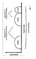
- Figure 1 depicts an example of aggregation of system carriers to achieve greater bandwidth. It may be noted that the left-most system carrier is well spaced-apart in frequency to the other system carriers. It will experience, and cause, only a small amount of Inter carrier interference due to the wide carrier spacing. However, the two right most system carriers are not as well spaced apart in frequency.
- ⁇ In a spectrum aggregated or multi-channel system as is discussed herein, several frequency bands, contiguous or non-contiguous, may be allocated for the communication with one mobile terminal.
- the modulation and access format within the band could be of any kind, e.g ., orthogonal frequency division multiplexing (OFDM), single-carrier frequency division multiplexing (SC-FDMA), code-division multiple access (CDMA) etc.
- OFDM orthogonal frequency division multiplexing
- SC-FDMA single-carrier frequency division multiplexing
- CDMA code-division multiple access
- a Third Generation Long Term Evolution (3G LTE) system is used as an example for explaining the invention.
- 3G LTE Third Generation Long Term Evolution
- the invention is not limited to such a system, but can be used as well in other systems.
- One example of another system, where the invention can be used is a High-Speed Packet Access (HSPA) system, in which dual-carrier can be used in the downlink and dual-cell can be used in the uplink.
- HSPA High-Speed Packet Access
- 4carrier or 4cell HSPA 4cell HSPA.
- a system carrier can be a 3G LTE component carrier or a HSPA dual carrier. It is noted that a non dual-cell HSPA (i.e. single HSPA carrier) capable terminal is capable to connect on such a system (HSPA) carrier, and that a non component carrier LTE (i.e. single carrier LTE) terminal is capable to connect on such a system (LTE) carrier.
- HSPA system
- LTE system
- This invention describes methods and devices for handling problems with multi-component carrier support in case of some kind of overload situation. For instance, depending on the battery status, the needed transmit power, real-time processing problem etc, there can be situations where the mobile terminal could not support multi-component carrier according to it's mobile terminal capability. In uplink it could e.g. be hard to fulfil spectrum leakage requirements, while in downlink it can be hard to fulfil blocking requirements. Different kind of radio architecture can be used for handling this problem, but they typically have drawbacks compared to standard continuous system bandwidth receivers in terms of current consumption.
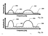
- Figures 2a and 2b illustrate a situation with uplink transmission from a mobile terminal on multiple component carriers.
- Figure 2a shows frequency leakage when transmitting with relatively low power from a mobile terminal to a base station.
- the transmit power level is typically chosen based on a predetermined quality level requirement. Closed power loops are commonly used to adjust the transmit power. The loops function by monitoring, in the base station, the quality level of the transmission. If the quality level drops below a predetermined threshold, a control signal is sent from the base station to the mobile terminal, which in return increases the transmit power. Reversely, If the quality rises above a predetermined threshold, the base station signals to the mobile terminal which then decreases the transmit power.
- Two component carriers 301, 302 are shown. Nonlinearities in the transmitter and RF power amplifier result in intermodulation distortion, this leads to frequency leakage. To enable other users to use the bandwidth positioned outside the bandwidths of the used component carriers, strict frequency leakage requirements apply on mobile terminals.
- 303 shows the frequency leakage of the two component carriers 301, 302, and 304 shows the leakage requirement of the mobile network. The frequency leakage 303 of the two component carriers 301, 302 is below the leakage requirement 304 when the transmit power of the carriers is low.
- Figure 2b shows frequency leakage when transmitting with a higher power from the mobile terminal to a base station.
- two non-contiguous component carriers 305,306 are shown. They are positioned at the same frequencies as the two component carriers 301,302 in figure 2a , however due to the increased transmit power their amplitude is higher.
- the spectrum leakage 307 of the two carriers is now above the spectrum leakage requirement of the mobile network. Using a more linear transmitter and RF power amplifier is a possible way to mitigate this. However, highly linear components generally consume more power and increase the complexity and cost of the mobile terminal.
- the number of component carriers based on the state of charge of the battery in the mobile terminal. This may be done by decreasing the number of component carriers used, when the state of charge of the battery is low, thereby achieving both multi carrier support and a long battery life time, without the need of a complex and expensive architecture in the mobile terminal.
- the number of component carriers used may also be controlled by a power management system functioning as a dynamic parameter.
- the power management system may function by estimating the power consumption of supporting multiple component carriers and determine the number of carriers to use in relation to the estimated power consumption. This may be done by limiting the number of component carriers used when the power consumption for supporting multiple component carriers is high.
- the state of charge of the battery in the mobile terminal may also be used as an input to the power management system. By using a power management system a longer battery life time is achieved. Thereby multiple component carriers may be supported only in situations where the power consumption for supporting them is relative low.
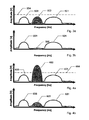
- Figures 3a, 3b, 4a and 4b illustrate a situation with downlink transmission to a mobile terminal on multiple component carriers.
- Figure 3a shows a frequency plot of an interference signal 502 with relatively low energy positioned between two component carriers 501, 503 prior to filtration in a mobile terminal.
- 504 is a threshold showing the ability of the filters in the mobile terminal to block out interference signals. The threshold is determined by the quality of the filters in the mobile terminal.
- the interference signal 502 has an amplitude that is lower than the threshold 504.
- Figure 3b shows a frequency plot of the same situation as depicted in figure 3a , after filtration in the mobile terminal.
- the power of the interference signal 505 has been minimized to an insignificant level, and a good quality of service is achieved for the two component carriers 501,502.
- Figure 4a shows a frequency plot of an interference signal 602 with a higher energy positioned between the two component carriers 601,603 prior to filtration in a mobile terminal.
- 604 is a threshold showing the ability of the filters in the mobile terminal to block out interference signals.
- the amplitude of the interference is in this situation higher than the threshold 604.
- Figure 4b shows a frequency plot of the same situation as depicted in figure 4a after filtration in the mobile terminal.
- the power of the interference signal 605 has been lowered, but it remains relatively high compared to the amplitude of the two component carriers 601,602 resulting in a poor quality of service of the carriers. This can be corrected by using high performance filters with a higher threshold; however this will again both increase the total power consumption and increase the overall cost of the device.
- Mobile terminals have transformed from being simple communication tools into being a fully operational transportable computer system, providing a range of different applications such as audio and movie applications, maps, dictionaries and games. This evolution has increased the need for processing power in mobile terminals. Multi carrier component support further increases the overall processing load of the mobile terminal.
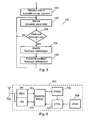
- FIG. 5 shows a flow chart of an embodiment of the present invention.
- the mobile terminal is connected to a multi component carrier network node. This may be achieved by using a cell search procedure.
- the mobile terminal receives information related to the available component carrier possibilities of the multi component carrier cell. This information may include information related to the bandwidth and carrier frequencies of the component carriers.
- the number of available component carriers may be any number, including the special case when only a single component carrier is available.
- the mobile terminal determines a subset of the available component carriers to use for transmitting and receiving data from and to the multi component carrier cell, i.e.
- the mobile terminal's capability to handle multiple component carriers including its capability to handle non-contiguous component carriers, and it informs the multi component carrier cell about this capability, typically via standard Radio Resource Control (RRC) signaling.
- RRC Radio Resource Control
- the choice may be based on the physical resources of the mobile terminal.
- the subset does not have to be a proper subset, meaning that the chosen subset may include all the possible component carriers received from the multi-carrier cell.
- step 102 the mobile terminal monitors dynamic parameters indicative of its current capability to handle non-contiguous component carriers, and from the detected parameters it is determined in step 103 whether a situation has occurred in which the mobile terminal's capability to handle non-contiguous component carriers has been reduced, i.e. whether a component carrier support event has occurred.
- events or situations may relate to parameters such as the battery level of the mobile terminal, the transmit power of the mobile terminal, the processing load of the mobile terminal, energy of interference signals, or data transfer requirements of applications on the mobile terminal. For instance, in case of low battery or high needed transmit power it could be difficult for the mobile terminal to support multi-component carrier transmission in uplink and/or downlink. In uplink it could e.g.
- a component carrier event is typically triggered by the level of one of the dynamic parameters passing a predefined threshold. However, it is noted that there may well be more than one threshold for a given parameter so that the capability of handling non-contiguous component carriers can be reduced in steps.
- a component carrier event may also be triggered by a combination of parameters passing their individual predefined thresholds. The combination may be any combination of the following parameters: the battery level of the mobile terminal, the transmit power of the mobile terminal, the processing load of the mobile terminal, energy of interference signals, or data transfer requirements of application on the mobile terminal. E.g. a component carrier event may be triggered by a combination of low battery level and high needed transmit power.
- step 104 the mobile terminal tries to reduce the likelihood for reception and/or transmission on multiple component carriers in order to still maintain the connection to the network node, i.e. not to drop the connection. This is done in step 104 by modifying or restricting feedback information transmitted to the network node about the signal quality on at least one of uplink and downlink component carriers and/or restricting the scheduling allocation needed (information transmitted to the network node) for either uplink or downlink.
- One way of doing this is to restrict the Channel-Quality Indicator (CQI) on a subset of the downlink component carriers, i.e. the terminal can start to report very low signal quality (i.e. a signal quality level that is lower than the actually received signal quality) on a subset of the component carriers, then reducing the likelihood of receiving data on these multiple component carriers.
- CQI Channel-Quality Indicator
- the mobile terminal can introduce a restriction in the requested uplink allocation, i.e. the mobile terminal can reduce the scheduling request size (by introducing constraints in the buffer status), so that the likelihood that the network node gives allocation over many uplink component carriers is reduced.
- uplink restrictions can be used in case sounding reference signals are transmitted in the uplink. Sounding reference signals or symbols are used by the network node to determine where to allocate uplink "chunks"/component carriers to a certain mobile terminal.
- the mobile terminal can bias the uplink sounding reference symbols on a subset of the component carriers to reduce the likelihood for scheduling allocation on multiple component carriers.
- the biasing could be implemented such that the transmitted reference symbols on some component carriers are transmitted with less gain, digitally adjusted in the signal generation part.
- the modified feedback information from step 104 is then transmitted from the mobile terminal to the base station in step 105.
- the mobile terminal may stay in this "restricted feedback mode" until a normal component carrier state is determined. For instance, the required transmit power becomes lower (than a threshold), the battery level comes back to a normal value, or the baseband processing is in synchronization again. Then the restriction of the feedback information is removed and the Channel-Quality Indicator reports etc goes back to normal mode again.
- Fig 6 shows a functional block diagram of a mobile terminal 701 configured to schedule data transmissions between the mobile terminal and a base station in a wireless communications network using the principles of the present invention.
- the mobile terminal comprises an antenna 702 for communicating with the base station using radio frequency signals.
- the radio frequency signals from the antenna is received in the radio frequency block 703, which has a reception part and a transmission part, and then processed in the baseband processing block 704.
- Information from the base station indicating available component carriers is then determined and stored in the available component carriers unit 705.
- the mobile terminal detects at least one dynamic parameter indicative of the mobile terminal's current ability to handle non-contiguous component carriers. The parameters are described above.
- the control block 707 determines from the at least one dynamic parameter whether a situation has occurred in which the mobile terminal's capability to handle non-contiguous component carriers has been reduced. As mentioned above, this is typically done by comparing the parameter value with a predetermined threshold. If it is determined that such a situation has occurred, the control block 707 modifies feedback information to the base station, and the modified information is then transmitted to the base station through the baseband processing block 704 and the transmitter part of the radio frequency block 703.
Description
- The invention relates to methods and devices for scheduling data transmissions between a mobile terminal and a base station in a wireless communications network arranged for the transmission of multiple independently scheduled component carrier signals.
- With each generation, wireless communication systems are characterized by ever-higher data rates. While some increase in data rates may be attributed to improvements in modulation, coding, and the like, significant increases in data rates generally require higher system bandwidths. For example, the International Mobile Telecommunications, IMT, advanced (a proposed fourth generation (4G) wireless communication system), mentions bandwidths up to 100 MHz. However, the radio spectrum is a limited resource, and since many operators and systems compete for limited radio resources, it is unlikely that 100 MHz of contiguous spectrum will be free for such systems.
- One approach to increasing bandwidth requirements in limited, fragmented spectrum is to aggregate non-contiguous spectrum. From a baseband point of view, this can effectively increase the system bandwidth sufficiently to support up to 1 Gb/s, a throughput requirement for 4G systems. Transmitting data in non-contiguous parts of the spectrum also introduces flexibility, as spectrum utilization may be adapted to existing spectrum use and geographical position. Additionally, different modulation and coding schemes may be advantageously applied to different portions of the spectrum.
- A possible evolution of current cellular systems, such as the 3GPP Long Term Evolution (LTE), to support non-contiguous spectrum is to introduce multiple component carriers or multiple channels. In such a multi-channel or multiple component carrier system, each separate portion of spectrum may be considered an LTE system. Multi-channel transmission is likely to be a principal part of the further releases of 3G LTE targeting ITU IMT-Advanced capabilities. A mobile terminal for use in such a system will be capable of receiving multiple component carriers, of different bandwidths, and transmitted at different carrier frequencies. Also High-Speed Packet Access (HSPA) systems can use multiple bands, e.g. dual carrier (downlink) and dual cell (uplink). In the following, the general term "multiple system carrier" is used.
-
US 2007/007090 discloses a multi-carrier communication system in which radio resources are distributed between a plurality of access terminals. The carriers assigned to an access terminal are determined by the network based on scheduling information received from the access terminal. The scheduling information may include data requirements, Quality-of-Service requirements, available transmit power headroom, the location of the access terminal, or hardware constraints associated with the access terminal. This disclosure does not relate to the use of non-contiguous bandwidths.
WO 2009/021012 discloses in one embodiment a wireless transmit/receive unit (WTRU) that from the network is assigned two separate carriers, a primary carrier and a secondary carrier. The WTRU is allowed to temporarily revert to single carrier reception for reception of e.g. overhead information even though dual carrier reception is still enabled and in this way decreases power consumption. This embodiment does not mention the use of contiguous or non-contiguous frequency bands.
Another embodiment ofWO 2009/021012 discloses a WTRU that monitors a set of dynamic device capabilities, and if required a "dynamic device capability" message is sent to the network. If a monitored parameter e.g. exceeds a threshold, the change in this parameter is reported in a "dynamic device capability" message. The embodiment does not mention the use of non-contiguous multiple carriers or multiple frequency bands. - The design of a mobile terminal supporting multiple non-contiguous system carriers is a non trivial task. The aggregated spectrum approach implies that the radio receiver architecture for such a mobile terminal will become more complicated than a terminal only capable to receive contiguous syste bandwidths. One reason for this is that the front end radio needs to be able to suppress blocking signal in between the spectrum "chunks". Different kinds of radio architecture can be used for handling this problem; however, they typically have drawbacks compared to standard contiguous system receivers in terms of current consumption. Therefore there is a need for an efficient non-contiguous multi-carrier system design taking into account the challenges in the mobile terminal front end receiver design.
- Therefore, it is an object of embodiments of the invention to provide a flexible method of scheduling data transmissions, which is more efficient and takes the mobile terminal's current ability to handle non-contiguous system carriers into account.
- According to embodiments of the invention the object is achieved by using a method of transmiting feedback information for scheduling data transmissions between a mobile terminal and a base station in a wireless communications network arranged for the transmission of multiple system carrier signals, each system carrier providing for the transmission of signals in a predetermined Frequency band around the carrier.
- The method comprises the steps of receiving in the mobile terminal information from said base station indicating available system carriers; detecting in the mobile terminal at least one dynamic parameter indicative of the mobile terminal's current capability to handle non-contiguous system carriers; determining in the mobile terminal from said at least one dynamic parameter whether a situation has occurred in which the mobile terminal's capability to handle non-contiguous system carriers has been reduced; modifying, if such a situation has occurred, feedback information to be transmitted to said base station to a level thta is lower than an actual level of said feedback information; and transmitting the modified feedback information from said mobile terminal to said base station.
- By modifying the feedback information in this way the mobile terminal reduces the likelihood that the base station allocates non-contiguous system carriers to the mobile terminal in the situations where the mobile terminal has a reduced capability of handling such system carriers.
- In some embodiments the system carrier signals may be transmitted in a Third Generation Long Term Evolution system or in a High-Speed Packet Access system.
- In one embodiment the method further comprises the step of selecting the at least one parameter from the group of parameters consisting of a parameter indicative of a charging level of a battery in the mobile terminal, a parameter indicative of a level of transmission power from the mobile terminal required to achieve a predetermined quality level of data transfer from the mobile terminal and a parameter indicative of a level of base band processing capability in the mobile terminal.
- By letting the mobile terminal control the number of system carrier to use in respect to a parameter indicative of a charging level of a battery in the mobile terminal, a longer battery lifetime may be achieved. This may be done by limiting the use of multiple component carriers when the battery charging level is low, thereby saving the power needed to support multiple component carriers. Additionally a simpler design of the mobile terminal may be used since there is no need for supporting multiple system carriers at a low battery voltage.
- By letting the parameter be indicative of a level of transmission power from the mobile terminal, to achieve a predetermined quality level of data transfer, a simpler design of the mobile terminal may be used, since the mobile terminal does not have to support multiple system carriers when transmitting with a high power. This may be achieved by limiting the number of system carriers used when transmitting with a high power.
- By letting the parameter be indicative of a level of base band processing capability in the mobile terminal a more efficient use of the processing resources in the mobile terminal may be achieved. This may be done by limiting the number of system carriers used when the processing resources in the mobile terminal is scarce.
- In one embodiment the method further comprises the steps of detecting the occurrence of a system carrier event triggered by one of the parameter levels passing a predefined threshold; and performing the step of determining whether a situation with reduced capability to handle system carriers having non contigeous frequency bands occurred when a system carrier event is detected.
- By controlling the use of multiple system carriers in respect to an event triggered by the passing of a predetermined threshold by one of the parameter levels, an easy implementation of the method in a mobile terminal is made possible.
- In one embodiment the step of modifying feedback information comprises reporting a Channel-Quality Indicator for at least one received system carrier indicating a signal quality level that is lower than an actually received signal quality. This reduces the likelihood of receiving downlink data on multiple component carriers.
- In one embodiment the step of modifying feedback information comprises reducing a scheduling request size indicating an amount of data to be transmitted to said base station. This increases the likelihood for only being uplink scheduled on one component carrier or fewer component carriers.
- In one embodiment the step of modifying feedback information comprises reducing a level of transmitted channel-sounding reference signals for at least one uplink system carrier. This reduces the likelihood for scheduling allocation on multiple uplink component carriers.
- Some embodiments of the invention relate to a mobile terminal configured to transmit feedback information for scheduling data transmissions between the mobile terminal and a base station in a wireless communications network arranged for the transmission of multiple system carrier signals, each system carrier providing for the transmission of signals in a predetermined frequensy bard around the carrier. The mobile terminal is configured to receive information from said base station indicating available system carriers; detect at least one dynamic parameter indicative of the mobile terminal's current capability to handle non-contiguous system carriers; determine from said at least one dynamic parameter whether a situation has occurred in which the mobile terminal's capability to handle non-contiguous system carriers has been reduced; modify, if such a situation has occurred, feedback information to be transmitted to said base station to a level that is lower than an actual level of said feed back information; and transmit the modified feedback information to said base station.
- Embodiments corresponding to those mentioned above for the method also apply for the mobile terminal.
- A further embodiment of the invention relates to a computer program with program code means for performing the method described above.
- Embodiments of the invention will now be described more fully below with reference to the drawings, in which
-
Figure 1 is a frequency plot showing multiple component carriers; -
Figure 2a is a frequency plot showing the spectrum leakage when transmitting multiple component carriers with low power; -
Figure 2b is a frequency plot showing the spectrum leakage when transmitting multiple component carriers with high power; -
Figure 3a is a frequency plot showing the amplitude of a low energy interference signal positioned between two component carriers prior to filtration; -
Figure 3b is a frequency plot showing the amplitude of a low energy interference signal positioned between two component carriers after filtration; -
Figure 4a is a frequency plot showing the amplitude of a high energy interference signal positioned between two component carriers prior to filtration; -
Figure 4b is a frequency plot showing the amplitude of a high energy interference signal positioned between two component carriers after filtration; and -
Figure 5 is a flow chart of a method of scheduling data transmissions between a mobile terminal and a base station; and -
Figure 6 is a functional block diagram of a mobile terminal. - In order to achieve higher bandwidths, e.g. up to 100 MHz, in wireless communications networks non-contiguous spectrum can be aggregated.
Figure 1 depicts an example of aggregation of system carriers to achieve greater bandwidth. It may be noted that the left-most system carrier is well spaced-apart in frequency to the other system carriers. It will experience, and cause, only a small amount of Inter carrier interference due to the wide carrier spacing. However, the two right most system carriers are not as well spaced apart in frequency. - In a spectrum aggregated or multi-channel system as is discussed herein, several frequency bands, contiguous or non-contiguous, may be allocated for the communication with one mobile terminal. The modulation and access format within the band could be of any kind, e.g., orthogonal frequency division multiplexing (OFDM), single-carrier frequency division multiplexing (SC-FDMA), code-division multiple access (CDMA) etc. In this application, we denote such a system "multiple component carrier system" or "multiple system carrier system". In this context, one channel is referred to as one "component carrier" or one "system carrier". It may also be noted that this type of system in some publications is called "multi-carrier", however, the term component carrier or system carrier is used here to avoid confusion with OFDM sub-carriers.
- In the following, a Third Generation Long Term Evolution (3G LTE) system is used as an example for explaining the invention. However, it is noted that the invention is not limited to such a system, but can be used as well in other systems. One example of another system, where the invention can be used, is a High-Speed Packet Access (HSPA) system, in which dual-carrier can be used in the downlink and dual-cell can be used in the uplink. In a new release HSPA will be extended to 4carrier or 4cell HSPA.
- Thus a system carrier can be a 3G LTE component carrier or a HSPA dual carrier. It is noted that a non dual-cell HSPA (i.e. single HSPA carrier) capable terminal is capable to connect on such a system (HSPA) carrier, and that a non component carrier LTE (i.e. single carrier LTE) terminal is capable to connect on such a system (LTE) carrier.
- Since 3G LTE uses the term "component carrier" this term is used in the following description for convenience instead of the more general term "system carrier".
- This invention describes methods and devices for handling problems with multi-component carrier support in case of some kind of overload situation. For instance, depending on the battery status, the needed transmit power, real-time processing problem etc, there can be situations where the mobile terminal could not support multi-component carrier according to it's mobile terminal capability. In uplink it could e.g. be hard to fulfil spectrum leakage requirements, while in downlink it can be hard to fulfil blocking requirements. Different kind of radio architecture can be used for handling this problem, but they typically have drawbacks compared to standard continuous system bandwidth receivers in terms of current consumption.
-
Figures 2a and 2b illustrate a situation with uplink transmission from a mobile terminal on multiple component carriers. -
Figure 2a shows frequency leakage when transmitting with relatively low power from a mobile terminal to a base station. The transmit power level is typically chosen based on a predetermined quality level requirement. Closed power loops are commonly used to adjust the transmit power. The loops function by monitoring, in the base station, the quality level of the transmission. If the quality level drops below a predetermined threshold, a control signal is sent from the base station to the mobile terminal, which in return increases the transmit power. Reversely, If the quality rises above a predetermined threshold, the base station signals to the mobile terminal which then decreases the transmit power. - Two
component carriers component carriers frequency leakage 303 of the twocomponent carriers leakage requirement 304 when the transmit power of the carriers is low. -
Figure 2b shows frequency leakage when transmitting with a higher power from the mobile terminal to a base station. Again, two non-contiguous component carriers 305,306 are shown. They are positioned at the same frequencies as the two component carriers 301,302 infigure 2a , however due to the increased transmit power their amplitude is higher. Thespectrum leakage 307 of the two carriers is now above the spectrum leakage requirement of the mobile network. Using a more linear transmitter and RF power amplifier is a possible way to mitigate this. However, highly linear components generally consume more power and increase the complexity and cost of the mobile terminal. - Thus it can be advantageous to control the number of component carriers based on the needed transmit power of the individual carriers. One way of doing this is to decrease the number of component carriers used, when the transmit power is high, i.e. above a predefined threshold. Alternatively, use of component carriers with a narrow bandwidth may be limited, when transmitting with high power. This will enable multi-carrier support on mobile termin als without the need of costly hardware and with reasonable power consumption.
- Similarly, it can be advantageous to control the number of component carriers based on the state of charge of the battery in the mobile terminal. This may be done by decreasing the number of component carriers used, when the state of charge of the battery is low, thereby achieving both multi carrier support and a long battery life time, without the need of a complex and expensive architecture in the mobile terminal.
- The number of component carriers used may also be controlled by a power management system functioning as a dynamic parameter. The power management system may function by estimating the power consumption of supporting multiple component carriers and determine the number of carriers to use in relation to the estimated power consumption. This may be done by limiting the number of component carriers used when the power consumption for supporting multiple component carriers is high. The state of charge of the battery in the mobile terminal may also be used as an input to the power management system. By using a power management system a longer battery life time is achieved. Thereby multiple component carriers may be supported only in situations where the power consumption for supporting them is relative low.
-
Figures 3a, 3b, 4a and 4b illustrate a situation with downlink transmission to a mobile terminal on multiple component carriers. -
Figure 3a shows a frequency plot of aninterference signal 502 with relatively low energy positioned between twocomponent carriers interference signal 502 has an amplitude that is lower than thethreshold 504.Figure 3b shows a frequency plot of the same situation as depicted infigure 3a , after filtration in the mobile terminal. The power of theinterference signal 505 has been minimized to an insignificant level, and a good quality of service is achieved for the two component carriers 501,502. -
Figure 4a shows a frequency plot of aninterference signal 602 with a higher energy positioned between the two component carriers 601,603 prior to filtration in a mobile terminal. 604 is a threshold showing the ability of the filters in the mobile terminal to block out interference signals. The amplitude of the interference is in this situation higher than thethreshold 604.Figure 4b shows a frequency plot of the same situation as depicted infigure 4a after filtration in the mobile terminal. The power of theinterference signal 605 has been lowered, but it remains relatively high compared to the amplitude of the two component carriers 601,602 resulting in a poor quality of service of the carriers. This can be corrected by using high performance filters with a higher threshold; however this will again both increase the total power consumption and increase the overall cost of the device. - Thus it can be advantageous to control the number of used component carriers based on the power of interference signals. This may be achieved by limiting the use of multi carrier components when high energy interference signals are present, thereby achieving good multi carrier support in the most common case, when no high energy interference signals are present, without the need of costly hardware to cope high energy interference signals.
- Mobile terminals have transformed from being simple communication tools into being a fully operational transportable computer system, providing a range of different applications such as audio and movie applications, maps, dictionaries and games. This evolution has increased the need for processing power in mobile terminals. Multi carrier component support further increases the overall processing load of the mobile terminal.
- Therefore, complicated applications might be processed slower when multi carrier components are used, resulting in a decreased user experience. Thus it can be advantageous to control the number of component carriers used in relation to the processing load of the mobile terminal. This can be achieved by using fewer component carriers when processing complicated applications, thereby securing a faster processing of complex application and an increased user experience.
-
Figure 5 shows a flow chart of an embodiment of the present invention. Instep 101 the mobile terminal is connected to a multi component carrier network node. This may be achieved by using a cell search procedure. The mobile terminal then receives information related to the available component carrier possibilities of the multi component carrier cell. This information may include information related to the bandwidth and carrier frequencies of the component carriers. The number of available component carriers may be any number, including the special case when only a single component carrier is available. The mobile terminal then determines a subset of the available component carriers to use for transmitting and receiving data from and to the multi component carrier cell, i.e. the mobile terminal's capability to handle multiple component carriers, including its capability to handle non-contiguous component carriers, and it informs the multi component carrier cell about this capability, typically via standard Radio Resource Control (RRC) signaling. The choice may be based on the physical resources of the mobile terminal. The subset does not have to be a proper subset, meaning that the chosen subset may include all the possible component carriers received from the multi-carrier cell. - Next, in
step 102 the mobile terminal monitors dynamic parameters indicative of its current capability to handle non-contiguous component carriers, and from the detected parameters it is determined instep 103 whether a situation has occurred in which the mobile terminal's capability to handle non-contiguous component carriers has been reduced, i.e. whether a component carrier support event has occurred. As described above, such events or situations may relate to parameters such as the battery level of the mobile terminal, the transmit power of the mobile terminal, the processing load of the mobile terminal, energy of interference signals, or data transfer requirements of applications on the mobile terminal. For instance, in case of low battery or high needed transmit power it could be difficult for the mobile terminal to support multi-component carrier transmission in uplink and/or downlink. In uplink it could e.g. be hard to fulfil spectrum leakage requirements, while in downlink it could e.g. be hard to fulfil blocking requirements. Another example could be some kind of overload in the real time processing in the baseband, making a large downlink reception over multiple component carriers risky in terms of risk for timing mismatch, which then in the end might give rise to a dropped connection. - The occurrence of a component carrier event is typically triggered by the level of one of the dynamic parameters passing a predefined threshold. However, it is noted that there may well be more than one threshold for a given parameter so that the capability of handling non-contiguous component carriers can be reduced in steps. Similarly, a component carrier event may also be triggered by a combination of parameters passing their individual predefined thresholds. The combination may be any combination of the following parameters: the battery level of the mobile terminal, the transmit power of the mobile terminal, the processing load of the mobile terminal, energy of interference signals, or data transfer requirements of application on the mobile terminal. E.g. a component carrier event may be triggered by a combination of low battery level and high needed transmit power.
- If an event is triggered, i.e. a situation with reduced capability to handle non-contiguous component carriers has occurred, then the mobile terminal tries to reduce the likelihood for reception and/or transmission on multiple component carriers in order to still maintain the connection to the network node, i.e. not to drop the connection. This is done in
step 104 by modifying or restricting feedback information transmitted to the network node about the signal quality on at least one of uplink and downlink component carriers and/or restricting the scheduling allocation needed (information transmitted to the network node) for either uplink or downlink. - One way of doing this is to restrict the Channel-Quality Indicator (CQI) on a subset of the downlink component carriers, i.e. the terminal can start to report very low signal quality (i.e. a signal quality level that is lower than the actually received signal quality) on a subset of the component carriers, then reducing the likelihood of receiving data on these multiple component carriers.
- As another example, to reduce the multiple uplink component carriers, the mobile terminal can introduce a restriction in the requested uplink allocation, i.e. the mobile terminal can reduce the scheduling request size (by introducing constraints in the buffer status), so that the likelihood that the network node gives allocation over many uplink component carriers is reduced.
- Another example of uplink restrictions can be used in case sounding reference signals are transmitted in the uplink. Sounding reference signals or symbols are used by the network node to determine where to allocate uplink "chunks"/component carriers to a certain mobile terminal. The mobile terminal can bias the uplink sounding reference symbols on a subset of the component carriers to reduce the likelihood for scheduling allocation on multiple component carriers. The biasing could be implemented such that the transmitted reference symbols on some component carriers are transmitted with less gain, digitally adjusted in the signal generation part.
- The modified feedback information from
step 104 is then transmitted from the mobile terminal to the base station instep 105. - The mobile terminal may stay in this "restricted feedback mode" until a normal component carrier state is determined. For instance, the required transmit power becomes lower (than a threshold), the battery level comes back to a normal value, or the baseband processing is in synchronization again. Then the restriction of the feedback information is removed and the Channel-Quality Indicator reports etc goes back to normal mode again.
-
Fig 6 shows a functional block diagram of amobile terminal 701 configured to schedule data transmissions between the mobile terminal and a base station in a wireless communications network using the principles of the present invention. The mobile terminal comprises anantenna 702 for communicating with the base station using radio frequency signals. The radio frequency signals from the antenna is received in theradio frequency block 703, which has a reception part and a transmission part, and then processed in thebaseband processing block 704. Information from the base station indicating available component carriers is then determined and stored in the availablecomponent carriers unit 705. Inblock 706 the mobile terminal detects at least one dynamic parameter indicative of the mobile terminal's current ability to handle non-contiguous component carriers. The parameters are described above. - The
control block 707 determines from the at least one dynamic parameter whether a situation has occurred in which the mobile terminal's capability to handle non-contiguous component carriers has been reduced. As mentioned above, this is typically done by comparing the parameter value with a predetermined threshold. If it is determined that such a situation has occurred, thecontrol block 707 modifies feedback information to the base station, and the modified information is then transmitted to the base station through thebaseband processing block 704 and the transmitter part of theradio frequency block 703. - Although various embodiments of the present invention have been described and shown, the invention is not restricted thereto, but may also be embodied in other ways within the scope of the subject-matter defined in the following claims.
Claims (15)
- A method of transmiting feedback information for sheduling data transmissions between a mobile terminal (701) and a base station in a wireless communications network arranged for the transmission of multiple system carrier signals, each system carrier providing for the transmission of signals in a predetermined frequency band around the carrier, the method comprising the step of receiving (101) in the mobile terminal (701) information from said base station indicating available system carriers; characterized in that the method further comprises the steps of:• detecting (102) in the mobile terminal (701) at least one dynamic parameter indicative of the mobile terminal's current capability to handle non-contiguous system carriers;• determining (103) in the mobile terminal (701) from said at least one dynamic parameter whether a situation has occurred in which the mobile terminal's capability to handle non-contiguous system carriers has been reduced;• modifying (104), if such a situation has occurred, feedback information to be transmitted to said base station to a level that is lower than an actual level of said feedback information; and• transmitting (105) the modified feedback information from said mobile terminal (701) to said base station.
- A method according to claim 1, wherein said system carrier signals are transmitted in a Third Generation Long Term Evolution system or in a High-Speed Packet Access system.
- A method according to claim 1 or 2, wherein the method further comprises the step of selecting said at least one parameter from the group of parameters consisting of:• a parameter indicative of a charging level of a battery in the mobile terminal;• a parameter indicative of a level of transmission power from the mobile terminal required to achieve a predetermined quality level of data transfer from the mobile terminal; and• a parameter indicative of a level of base band processing capability in the mobile terminal.
- A method according to claim 3, wherein the method further comprises the steps of:• detecting the occurrence of a system carrier event triggered by one of said parameter levels passing a predefined threshold; and• performing the step of determining whether a situation with reduced capability to handle system carriers having non-contiguous frequency bands has occurred when a system carrier event is detected.
- A method according to any one of claims 1 to 4, wherein the step of modifying feedback information comprises• reporting a Channel-Quality Indicator for at least one received system carrier indicating a signal quality level that is lower than an actually received signal quality.
- A method according to any one of claims 1 to 5, wherein the step of modifying feedback information comprises• reducing a scheduling request size indicating an amount of data to be transmitted to said base station.
- A method according to any one of claims 1 to 6, wherein the step of modifying feedback information comprises• reducing a level of transmitted channel-sounding reference signals for at least one uplink system carrier.
- A mobile terminal configured to transmit feedback information for schedaling data transmissions between the mobile terminal (701) and a base station in a wireless communications network arranged for the transmission of multiple system carrier signals, each system carrier providing for the transmission of signals in a predetermined frequency band around the carrier, the mobile terminal being configured to receive (703, 704, 705) information from said base station indicating available system carriers; characterized in that the mobile terminal is further configured to:• detect (706) at least one dynamic parameter indicative of the mobile terminal's current capability to handle non-contiguous system carriers;• determine (707) from said at least one dynamic parameter whether a situation has occurred in which the mobile terminal's capability to handle non-contiguous system carriers has been reduced;• modify, if such a situation has occurred, feedback information to be transmitted to said base station to a level that is lower than an actual level of said feedback information; and• transmit (702, 703) the modified feedback information to said base station.
- A mobile terminal according to claim 8, wherein the mobile terminal is configured to be used in a Third Generation Long Term Evolution system or in a High-Speed Packet Access system.
- A mobile terminal according to claim 8 or 9, wherein the mobile terminal is further configured to select said at least one parameter from the group of parameters consisting of:• a parameter indicative of a charging level of a battery in the mobile terminal;• a parameter indicative of a level of transmission power from the mobile terminal required to achieve a predetermined quality level of data transfer from the mobile terminal; and• a parameter indicative of a level of base band processing capability in the mobile terminal.
- A mobile terminal according to claim 10, wherein the mobile terminal is further configured to:• detect the occurrence of a system carrier event triggered by one of said parameter levels passing a predefined threshold; and• determine whether a situation with reduced capability to handle non-contiguous system carriers has occurred when a system carrier event is detected.
- A mobile terminal according to any one of claims 8 to 11, wherein the mobile terminal is configured to modify feedback information by• reporting a Channel-Quality Indicator for at least one received system carrier indicating a signal quality level that is lower than an actually received signal quality.
- A mobile terminal according to any one of claims 8 to 12, wherein the mobile terminal is configured to modify feedback information by• reducing a scheduling request size indicating an amount of data to be transmitted to said base station.
- A mobile terminal according to any one of claims 8 to 13, wherein the mobile terminal is configured to modify feedback information by• reducing a level of transmitted channel-sounding reference signals for at least one uplink system carrier.
- A computer program comprising program code means for performing the steps of any one of the claims 1 to 7 when said computer program is run on a computer.
Applications Claiming Priority (2)
| Application Number | Priority Date | Filing Date | Title |
|---|---|---|---|
| US18773209P | 2009-06-17 | 2009-06-17 | |
| PCT/EP2010/057714 WO2010145938A1 (en) | 2009-06-17 | 2010-06-02 | Scheduling data transmissions between a mobile terminal and a base station in a wireless communications network |
Publications (2)
| Publication Number | Publication Date |
|---|---|
| EP2443893A1 EP2443893A1 (en) | 2012-04-25 |
| EP2443893B1 true EP2443893B1 (en) | 2013-05-01 |
Family
ID=42651387
Family Applications (2)
| Application Number | Title | Priority Date | Filing Date |
|---|---|---|---|
| EP10721171.6A Active EP2443893B1 (en) | 2009-06-17 | 2010-06-02 | Scheduling data transmissions between a mobile terminal and a base station in a wireless communications network |
| EP10721172.4A Active EP2443851B1 (en) | 2009-06-17 | 2010-06-02 | Scheduling data transmissions between a mobile terminal and a base station in a wireless communications network |
Family Applications After (1)
| Application Number | Title | Priority Date | Filing Date |
|---|---|---|---|
| EP10721172.4A Active EP2443851B1 (en) | 2009-06-17 | 2010-06-02 | Scheduling data transmissions between a mobile terminal and a base station in a wireless communications network |
Country Status (8)
| Country | Link |
|---|---|
| US (2) | US8750227B2 (en) |
| EP (2) | EP2443893B1 (en) |
| JP (1) | JP5666572B2 (en) |
| CN (1) | CN102804898B (en) |
| BR (1) | BRPI1016091A2 (en) |
| IN (1) | IN2012DN00268A (en) |
| SG (1) | SG176593A1 (en) |
| WO (2) | WO2010145939A1 (en) |
Families Citing this family (25)
| Publication number | Priority date | Publication date | Assignee | Title |
|---|---|---|---|---|
| WO2010145939A1 (en) | 2009-06-17 | 2010-12-23 | Telefonaktiebolaget Lm Ericsson (Publ) | Scheduling data transmissions between a mobile terminal and a base station in a wireless communications network |
| US9137757B2 (en) * | 2010-02-11 | 2015-09-15 | Qualcomm Incorporated | Method and apparatus for power control in high speed packet access (HSPA) networks |
| US9107227B2 (en) * | 2010-02-16 | 2015-08-11 | Nokia Technologies Oy | Activation and deactivation of component carrier measurements based on thresh-old settings |
| US9001750B2 (en) | 2010-04-05 | 2015-04-07 | Qualcomm Incorporated | Method and apparatus for signaling user equipment capabilities |
| US9819458B2 (en) * | 2010-08-13 | 2017-11-14 | Qualcomm Incorporation | Feedback bundling for power-limited devices in wireless communications |
| CN103404216B (en) * | 2011-01-11 | 2018-08-17 | 诺基亚通信公司 | The method and apparatus of non-adjacent carrier signalling in multi-carrier broadband wireless system |
| US8929311B2 (en) | 2011-02-08 | 2015-01-06 | Telefonaktiebolaget L M Ericsson (Publ) | Signaling for legacy terminal operation in harmonized bands |
| US8503322B2 (en) * | 2011-02-21 | 2013-08-06 | Motorola Mobility Llc | IQ imbalance image compensation in multi-carrier wireless communication systems |
| US8619716B2 (en) | 2011-02-21 | 2013-12-31 | Motorola Mobility Llc | IQ imbalance image compensation in multi-carrier wireless communication systems |
| US20120214540A1 (en) | 2011-02-21 | 2012-08-23 | Motorola Mobility, Inc. | Signal Measurement on Component Carriers in Wireless Communication Systems |
| US8666321B2 (en) | 2011-02-21 | 2014-03-04 | Motorola Mobility Llc | Signal measurement on component carriers in wireless communication systems |
| US9686062B2 (en) * | 2011-03-04 | 2017-06-20 | Alcatel Lucent | Virtual aggregation of fragmented wireless spectrum |
| EP2801233A1 (en) * | 2012-01-02 | 2014-11-12 | Nokia Solutions and Networks Oy | Rate capping with multiple carrier aggregation schedulers |
| JP5953079B2 (en) * | 2012-03-16 | 2016-07-13 | 株式会社Nttドコモ | Mobile communication method, radio base station, and mobile station |
| US20130322370A1 (en) * | 2012-06-01 | 2013-12-05 | Qualcomm Incorporated | Signaling reduced user equipment performance in wireless communication systems |
| US9615336B2 (en) * | 2013-05-23 | 2017-04-04 | Qualcomm Incorporated | Uplink power headroom management for connectivity with logically separate cells |
| US11350348B2 (en) * | 2014-03-13 | 2022-05-31 | Intel Corporation | Method for the transfer of radio capability information |
| US9693312B2 (en) * | 2014-11-03 | 2017-06-27 | Intel Corporation | Communication terminal and method for controlling power consumption of a communication terminal |
| US9775154B2 (en) * | 2015-10-15 | 2017-09-26 | Alcatel-Lucent Usa Inc. | Dynamic selection of band combinations for carrier aggregation |
| EP3456104B1 (en) * | 2016-05-12 | 2021-07-07 | Telefonaktiebolaget LM Ericsson (publ) | Communication device and method therein for handling operating modes in wireless communication network |
| US10873952B2 (en) * | 2017-11-30 | 2020-12-22 | Google Llc | LTE resource allocation |
| KR102562310B1 (en) * | 2018-09-27 | 2023-08-01 | 삼성전자주식회사 | Wireless communication apparatus adaptively changing capability and method of operation thereof |
| KR20200050852A (en) * | 2018-11-02 | 2020-05-12 | 삼성전자주식회사 | Method and apparatus for handling overheat of electronic apparatus |
| US10979892B2 (en) * | 2019-07-30 | 2021-04-13 | At&T Intellectual Property I, L.P. | Efficient device capabilities enquiry for 5G or other next generations wireless network |
| US11683804B2 (en) * | 2020-10-28 | 2023-06-20 | Qualcomm Incorporated | Uplink allocation in wireless communication systems |
Family Cites Families (30)
| Publication number | Priority date | Publication date | Assignee | Title |
|---|---|---|---|---|
| GB2355367A (en) | 1999-10-13 | 2001-04-18 | Ericsson Telefon Ab L M | Adjusting allocation of transmission slots according operating conditions in a mobile telephone |
| GB2386507A (en) | 2002-03-15 | 2003-09-17 | Ubinetics Ltd | Controlling transmission rate |
| US7124859B2 (en) | 2003-04-25 | 2006-10-24 | Snap-On Incorporated | Manually actuated brake system for manually towable vehicle |
| EP1530383B1 (en) | 2003-11-10 | 2006-06-14 | Research In Motion Limited | Methods and system for limiting communication capabilities in mobile communication devices |
| US7957351B2 (en) | 2005-04-04 | 2011-06-07 | Qualcomm Incorporated | Method and apparatus for management of multi-carrier communications in a wireless communication system |
| US7570975B2 (en) | 2005-10-26 | 2009-08-04 | Motorola, Inc. | Method and apparatus for management of low-battery mobile stations |
| EP1793520B1 (en) | 2005-11-30 | 2012-02-29 | Panasonic Corporation | Configurable acknowledgement mode for a hybrid automatic repeat request protocol |
| US7860502B2 (en) | 2005-12-10 | 2010-12-28 | Samsung Electronics Co., Ltd. | Apparatus and method for hard handover in a wireless communication system |
| TW200805925A (en) | 2006-05-12 | 2008-01-16 | Interdigital Tech Corp | Method and system for signaling performance requirements of a wireless transmit/receive unit |
| US10014931B2 (en) | 2007-01-13 | 2018-07-03 | Samsung Electronics Co., Ltd. | Method and system for transmitting and receiving signal using multiple frequency bands in a wireless communication system |
| US8090369B2 (en) | 2007-05-01 | 2012-01-03 | Qualcomm Incorporated | User equipment capability handling in long-term evolution systems |
| JP5138293B2 (en) * | 2007-07-05 | 2013-02-06 | 富士通株式会社 | Communication apparatus and method for controlling reception diversity |
| US20090163158A1 (en) * | 2007-08-07 | 2009-06-25 | Interdigital Patent Holdings, Inc. | Support of downlink dual carriers and other features of evolved geran networks |
| US20090093255A1 (en) * | 2007-10-05 | 2009-04-09 | Qualcomm Incorporated | Adjusting multi-carrier allocation in wireless networks |
| EP2077690B1 (en) | 2008-01-07 | 2015-03-18 | LG Electronics Inc. | Method of reselecting a cell based on priorities |
| US8086229B2 (en) | 2008-02-25 | 2011-12-27 | Telefonaktiebolaget L M Ericsson (Publ) | Alleviating mobile device overload conditions in a mobile communication system |
| US8711785B2 (en) | 2008-03-25 | 2014-04-29 | Qualcomm Incorporated | Fast carrier allocation in multi-carrier systems |
| US8699467B2 (en) | 2008-03-25 | 2014-04-15 | Telefonaktiebolaget Lm Ericsson (Publ) | Anchor carrier selection in multi-carrier wireless network |
| US8934405B2 (en) | 2008-05-06 | 2015-01-13 | Telefonaktiebolaget L M Ericsson (Publ) | Method and apparatus for retransmission scheduling and control in multi-carrier wireless communication networks |
| CN101287184B (en) | 2008-05-22 | 2012-05-23 | 中兴通讯股份有限公司 | Method for signaling transmitting and receiving in multi-carrier frequency communication system |
| JP5410524B2 (en) * | 2008-08-08 | 2014-02-05 | ノキア シーメンス ネットワークス オサケユキチュア | Apparatus and method for controlling output of mobile station |
| EP2182754B1 (en) | 2008-10-30 | 2014-01-15 | Telefonaktiebolaget LM Ericsson (publ) | Method and receiver for estimating and reporting a channel quality measure |
| US8514793B2 (en) * | 2008-10-31 | 2013-08-20 | Interdigital Patent Holdings, Inc. | Method and apparatus for monitoring and processing component carriers |
| WO2010053984A2 (en) | 2008-11-04 | 2010-05-14 | Nortel Networks Limited | Providing a downlink control structure in a first carrier to indicate control information in a second, different carrier |
| WO2010091425A2 (en) | 2009-02-09 | 2010-08-12 | Interdigital Patent Holdings, Inc. | Apparatus and method for uplink power control for a wireless transmitter/receiver unit utilizing multiple carriers |
| TWI407738B (en) * | 2009-04-24 | 2013-09-01 | Mediatek Inc | Carrier assignment method and base station |
| US8559387B2 (en) * | 2009-05-04 | 2013-10-15 | Blackberry Limited | Indicating radio access technology information to mobile stations system and method |
| WO2010145939A1 (en) | 2009-06-17 | 2010-12-23 | Telefonaktiebolaget Lm Ericsson (Publ) | Scheduling data transmissions between a mobile terminal and a base station in a wireless communications network |
| EP3182775A1 (en) | 2009-06-17 | 2017-06-21 | IDTP Holdings, Inc. | Scheduling data transmissions between a mobile terminal and a base station in a wireless communications network |
| US8422539B2 (en) * | 2010-08-19 | 2013-04-16 | Industrial Technology Research Institute | Multi-carrier receiver, multi-carrier transmitter and multi-carrier transceiver system |
-
2010
- 2010-06-02 WO PCT/EP2010/057715 patent/WO2010145939A1/en active Application Filing
- 2010-06-02 US US13/378,127 patent/US8750227B2/en active Active
- 2010-06-02 CN CN201080027685.9A patent/CN102804898B/en active Active
- 2010-06-02 US US13/377,165 patent/US8958376B2/en active Active
- 2010-06-02 SG SG2011086386A patent/SG176593A1/en unknown
- 2010-06-02 JP JP2012515419A patent/JP5666572B2/en not_active Expired - Fee Related
- 2010-06-02 WO PCT/EP2010/057714 patent/WO2010145938A1/en active Application Filing
- 2010-06-02 IN IN268DEN2012 patent/IN2012DN00268A/en unknown
- 2010-06-02 EP EP10721171.6A patent/EP2443893B1/en active Active
- 2010-06-02 BR BRPI1016091A patent/BRPI1016091A2/en not_active IP Right Cessation
- 2010-06-02 EP EP10721172.4A patent/EP2443851B1/en active Active
Also Published As
| Publication number | Publication date |
|---|---|
| WO2010145939A1 (en) | 2010-12-23 |
| JP2012530438A (en) | 2012-11-29 |
| JP5666572B2 (en) | 2015-02-12 |
| BRPI1016091A2 (en) | 2017-07-18 |
| US20120127905A1 (en) | 2012-05-24 |
| CN102804898A (en) | 2012-11-28 |
| WO2010145938A1 (en) | 2010-12-23 |
| SG176593A1 (en) | 2012-01-30 |
| EP2443851B1 (en) | 2018-01-17 |
| EP2443893A1 (en) | 2012-04-25 |
| US8750227B2 (en) | 2014-06-10 |
| US20120113935A1 (en) | 2012-05-10 |
| US8958376B2 (en) | 2015-02-17 |
| EP2443851A1 (en) | 2012-04-25 |
| CN102804898B (en) | 2015-07-15 |
| IN2012DN00268A (en) | 2015-05-08 |
Similar Documents
| Publication | Publication Date | Title |
|---|---|---|
| EP2443893B1 (en) | Scheduling data transmissions between a mobile terminal and a base station in a wireless communications network | |
| US11818060B2 (en) | Scheduling data transmissions between a mobile terminal and a base station in a wireless communications network using component carriers | |
| US9532319B2 (en) | Method and apparatus for power control | |
| US8848729B2 (en) | Allocation method for physical downlink control channel, base station and user terminal | |
| EP2760152B1 (en) | Method, user equipment, and base station for information transmission | |
| EP2426973A1 (en) | User device, base station device, and communication control method | |
| KR20110139078A (en) | Method and apparatus for setting uplink transmission power in mobile communication system | |
| EP2408129B1 (en) | Radio communication system, radio transmission device and radio transmission method | |
| CN109937551B (en) | Radio node and method of operating a radio node | |
| EP3446528A1 (en) | Improving communication quality between a wireless communication node, and wireless communication devices | |
| US9877287B2 (en) | Methods and nodes for controlling uplink power in a radio network | |
| CN107210876B (en) | Inter-mode carrier aggregation |
Legal Events
| Date | Code | Title | Description |
|---|---|---|---|
| PUAI | Public reference made under article 153(3) epc to a published international application that has entered the european phase |
Free format text: ORIGINAL CODE: 0009012 |
|
| 17P | Request for examination filed |
Effective date: 20120105 |
|
| AK | Designated contracting states |
Kind code of ref document: A1 Designated state(s): AL AT BE BG CH CY CZ DE DK EE ES FI FR GB GR HR HU IE IS IT LI LT LU LV MC MK MT NL NO PL PT RO SE SI SK SM TR |
|
| DAX | Request for extension of the european patent (deleted) | ||
| GRAP | Despatch of communication of intention to grant a patent |
Free format text: ORIGINAL CODE: EPIDOSNIGR1 |
|
| GRAS | Grant fee paid |
Free format text: ORIGINAL CODE: EPIDOSNIGR3 |
|
| GRAA | (expected) grant |
Free format text: ORIGINAL CODE: 0009210 |
|
| AK | Designated contracting states |
Kind code of ref document: B1 Designated state(s): AL AT BE BG CH CY CZ DE DK EE ES FI FR GB GR HR HU IE IS IT LI LT LU LV MC MK MT NL NO PL PT RO SE SI SK SM TR |
|
| REG | Reference to a national code |
Ref country code: GB Ref legal event code: FG4D |
|
| REG | Reference to a national code |
Ref country code: AT Ref legal event code: REF Ref document number: 610582 Country of ref document: AT Kind code of ref document: T Effective date: 20130515 Ref country code: CH Ref legal event code: EP |
|
| REG | Reference to a national code |
Ref country code: IE Ref legal event code: FG4D |
|
| REG | Reference to a national code |
Ref country code: DE Ref legal event code: R096 Ref document number: 602010006732 Country of ref document: DE Effective date: 20130704 |
|
| REG | Reference to a national code |
Ref country code: AT Ref legal event code: MK05 Ref document number: 610582 Country of ref document: AT Kind code of ref document: T Effective date: 20130501 |
|
| REG | Reference to a national code |
Ref country code: NL Ref legal event code: VDEP Effective date: 20130501 |
|
| REG | Reference to a national code |
Ref country code: LT Ref legal event code: MG4D |
|
| PG25 | Lapsed in a contracting state [announced via postgrant information from national office to epo] |
Ref country code: AT Free format text: LAPSE BECAUSE OF FAILURE TO SUBMIT A TRANSLATION OF THE DESCRIPTION OR TO PAY THE FEE WITHIN THE PRESCRIBED TIME-LIMIT Effective date: 20130501 Ref country code: SI Free format text: LAPSE BECAUSE OF FAILURE TO SUBMIT A TRANSLATION OF THE DESCRIPTION OR TO PAY THE FEE WITHIN THE PRESCRIBED TIME-LIMIT Effective date: 20130501 Ref country code: GR Free format text: LAPSE BECAUSE OF FAILURE TO SUBMIT A TRANSLATION OF THE DESCRIPTION OR TO PAY THE FEE WITHIN THE PRESCRIBED TIME-LIMIT Effective date: 20130802 Ref country code: FI Free format text: LAPSE BECAUSE OF FAILURE TO SUBMIT A TRANSLATION OF THE DESCRIPTION OR TO PAY THE FEE WITHIN THE PRESCRIBED TIME-LIMIT Effective date: 20130501 Ref country code: IS Free format text: LAPSE BECAUSE OF FAILURE TO SUBMIT A TRANSLATION OF THE DESCRIPTION OR TO PAY THE FEE WITHIN THE PRESCRIBED TIME-LIMIT Effective date: 20130901 Ref country code: PT Free format text: LAPSE BECAUSE OF FAILURE TO SUBMIT A TRANSLATION OF THE DESCRIPTION OR TO PAY THE FEE WITHIN THE PRESCRIBED TIME-LIMIT Effective date: 20130902 Ref country code: SE Free format text: LAPSE BECAUSE OF FAILURE TO SUBMIT A TRANSLATION OF THE DESCRIPTION OR TO PAY THE FEE WITHIN THE PRESCRIBED TIME-LIMIT Effective date: 20130501 Ref country code: ES Free format text: LAPSE BECAUSE OF FAILURE TO SUBMIT A TRANSLATION OF THE DESCRIPTION OR TO PAY THE FEE WITHIN THE PRESCRIBED TIME-LIMIT Effective date: 20130812 Ref country code: LT Free format text: LAPSE BECAUSE OF FAILURE TO SUBMIT A TRANSLATION OF THE DESCRIPTION OR TO PAY THE FEE WITHIN THE PRESCRIBED TIME-LIMIT Effective date: 20130501 Ref country code: NO Free format text: LAPSE BECAUSE OF FAILURE TO SUBMIT A TRANSLATION OF THE DESCRIPTION OR TO PAY THE FEE WITHIN THE PRESCRIBED TIME-LIMIT Effective date: 20130801 |
|
| PG25 | Lapsed in a contracting state [announced via postgrant information from national office to epo] |
Ref country code: HR Free format text: LAPSE BECAUSE OF FAILURE TO SUBMIT A TRANSLATION OF THE DESCRIPTION OR TO PAY THE FEE WITHIN THE PRESCRIBED TIME-LIMIT Effective date: 20130501 Ref country code: CY Free format text: LAPSE BECAUSE OF FAILURE TO SUBMIT A TRANSLATION OF THE DESCRIPTION OR TO PAY THE FEE WITHIN THE PRESCRIBED TIME-LIMIT Effective date: 20130501 Ref country code: BG Free format text: LAPSE BECAUSE OF FAILURE TO SUBMIT A TRANSLATION OF THE DESCRIPTION OR TO PAY THE FEE WITHIN THE PRESCRIBED TIME-LIMIT Effective date: 20130801 Ref country code: PL Free format text: LAPSE BECAUSE OF FAILURE TO SUBMIT A TRANSLATION OF THE DESCRIPTION OR TO PAY THE FEE WITHIN THE PRESCRIBED TIME-LIMIT Effective date: 20130501 |
|
| PG25 | Lapsed in a contracting state [announced via postgrant information from national office to epo] |
Ref country code: LV Free format text: LAPSE BECAUSE OF FAILURE TO SUBMIT A TRANSLATION OF THE DESCRIPTION OR TO PAY THE FEE WITHIN THE PRESCRIBED TIME-LIMIT Effective date: 20130501 |
|
| PG25 | Lapsed in a contracting state [announced via postgrant information from national office to epo] |
Ref country code: DK Free format text: LAPSE BECAUSE OF FAILURE TO SUBMIT A TRANSLATION OF THE DESCRIPTION OR TO PAY THE FEE WITHIN THE PRESCRIBED TIME-LIMIT Effective date: 20130501 Ref country code: MC Free format text: LAPSE BECAUSE OF FAILURE TO SUBMIT A TRANSLATION OF THE DESCRIPTION OR TO PAY THE FEE WITHIN THE PRESCRIBED TIME-LIMIT Effective date: 20130501 Ref country code: SK Free format text: LAPSE BECAUSE OF FAILURE TO SUBMIT A TRANSLATION OF THE DESCRIPTION OR TO PAY THE FEE WITHIN THE PRESCRIBED TIME-LIMIT Effective date: 20130501 Ref country code: EE Free format text: LAPSE BECAUSE OF FAILURE TO SUBMIT A TRANSLATION OF THE DESCRIPTION OR TO PAY THE FEE WITHIN THE PRESCRIBED TIME-LIMIT Effective date: 20130501 Ref country code: BE Free format text: LAPSE BECAUSE OF FAILURE TO SUBMIT A TRANSLATION OF THE DESCRIPTION OR TO PAY THE FEE WITHIN THE PRESCRIBED TIME-LIMIT Effective date: 20130501 Ref country code: CZ Free format text: LAPSE BECAUSE OF FAILURE TO SUBMIT A TRANSLATION OF THE DESCRIPTION OR TO PAY THE FEE WITHIN THE PRESCRIBED TIME-LIMIT Effective date: 20130501 |
|
| PG25 | Lapsed in a contracting state [announced via postgrant information from national office to epo] |
Ref country code: IT Free format text: LAPSE BECAUSE OF FAILURE TO SUBMIT A TRANSLATION OF THE DESCRIPTION OR TO PAY THE FEE WITHIN THE PRESCRIBED TIME-LIMIT Effective date: 20130501 Ref country code: NL Free format text: LAPSE BECAUSE OF FAILURE TO SUBMIT A TRANSLATION OF THE DESCRIPTION OR TO PAY THE FEE WITHIN THE PRESCRIBED TIME-LIMIT Effective date: 20130501 Ref country code: RO Free format text: LAPSE BECAUSE OF FAILURE TO SUBMIT A TRANSLATION OF THE DESCRIPTION OR TO PAY THE FEE WITHIN THE PRESCRIBED TIME-LIMIT Effective date: 20130501 |
|
| PLBE | No opposition filed within time limit |
Free format text: ORIGINAL CODE: 0009261 |
|
| STAA | Information on the status of an ep patent application or granted ep patent |
Free format text: STATUS: NO OPPOSITION FILED WITHIN TIME LIMIT |
|
| REG | Reference to a national code |
Ref country code: IE Ref legal event code: MM4A |
|
| 26N | No opposition filed |
Effective date: 20140204 |
|
| PG25 | Lapsed in a contracting state [announced via postgrant information from national office to epo] |
Ref country code: IE Free format text: LAPSE BECAUSE OF NON-PAYMENT OF DUE FEES Effective date: 20130602 |
|
| REG | Reference to a national code |
Ref country code: DE Ref legal event code: R097 Ref document number: 602010006732 Country of ref document: DE Effective date: 20140204 |
|
| REG | Reference to a national code |
Ref country code: CH Ref legal event code: PL |
|
| PG25 | Lapsed in a contracting state [announced via postgrant information from national office to epo] |
Ref country code: MT Free format text: LAPSE BECAUSE OF FAILURE TO SUBMIT A TRANSLATION OF THE DESCRIPTION OR TO PAY THE FEE WITHIN THE PRESCRIBED TIME-LIMIT Effective date: 20130501 |
|
| PG25 | Lapsed in a contracting state [announced via postgrant information from national office to epo] |
Ref country code: CH Free format text: LAPSE BECAUSE OF NON-PAYMENT OF DUE FEES Effective date: 20140630 Ref country code: LI Free format text: LAPSE BECAUSE OF NON-PAYMENT OF DUE FEES Effective date: 20140630 |
|
| PG25 | Lapsed in a contracting state [announced via postgrant information from national office to epo] |
Ref country code: SM Free format text: LAPSE BECAUSE OF FAILURE TO SUBMIT A TRANSLATION OF THE DESCRIPTION OR TO PAY THE FEE WITHIN THE PRESCRIBED TIME-LIMIT Effective date: 20130501 |
|
| PG25 | Lapsed in a contracting state [announced via postgrant information from national office to epo] |
Ref country code: TR Free format text: LAPSE BECAUSE OF FAILURE TO SUBMIT A TRANSLATION OF THE DESCRIPTION OR TO PAY THE FEE WITHIN THE PRESCRIBED TIME-LIMIT Effective date: 20130501 |
|
| PG25 | Lapsed in a contracting state [announced via postgrant information from national office to epo] |
Ref country code: MK Free format text: LAPSE BECAUSE OF FAILURE TO SUBMIT A TRANSLATION OF THE DESCRIPTION OR TO PAY THE FEE WITHIN THE PRESCRIBED TIME-LIMIT Effective date: 20130501 Ref country code: LU Free format text: LAPSE BECAUSE OF NON-PAYMENT OF DUE FEES Effective date: 20130602 Ref country code: HU Free format text: LAPSE BECAUSE OF FAILURE TO SUBMIT A TRANSLATION OF THE DESCRIPTION OR TO PAY THE FEE WITHIN THE PRESCRIBED TIME-LIMIT; INVALID AB INITIO Effective date: 20100602 |
|
| REG | Reference to a national code |
Ref country code: FR Ref legal event code: PLFP Year of fee payment: 7 |
|
| REG | Reference to a national code |
Ref country code: FR Ref legal event code: PLFP Year of fee payment: 8 |
|
| REG | Reference to a national code |
Ref country code: FR Ref legal event code: PLFP Year of fee payment: 9 |
|
| PG25 | Lapsed in a contracting state [announced via postgrant information from national office to epo] |
Ref country code: AL Free format text: LAPSE BECAUSE OF FAILURE TO SUBMIT A TRANSLATION OF THE DESCRIPTION OR TO PAY THE FEE WITHIN THE PRESCRIBED TIME-LIMIT Effective date: 20130501 |
|
| PGFP | Annual fee paid to national office [announced via postgrant information from national office to epo] |
Ref country code: FR Payment date: 20190625 Year of fee payment: 10 |
|
| PG25 | Lapsed in a contracting state [announced via postgrant information from national office to epo] |
Ref country code: FR Free format text: LAPSE BECAUSE OF NON-PAYMENT OF DUE FEES Effective date: 20200630 |
|
| PGFP | Annual fee paid to national office [announced via postgrant information from national office to epo] |
Ref country code: DE Payment date: 20230626 Year of fee payment: 14 |
|
| PGFP | Annual fee paid to national office [announced via postgrant information from national office to epo] |
Ref country code: GB Payment date: 20230627 Year of fee payment: 14 |