EP2408129B1 - Radio communication system, radio transmission device and radio transmission method - Google Patents
Radio communication system, radio transmission device and radio transmission method Download PDFInfo
- Publication number
- EP2408129B1 EP2408129B1 EP10750618.0A EP10750618A EP2408129B1 EP 2408129 B1 EP2408129 B1 EP 2408129B1 EP 10750618 A EP10750618 A EP 10750618A EP 2408129 B1 EP2408129 B1 EP 2408129B1
- Authority
- EP
- European Patent Office
- Prior art keywords
- system frequency
- frequency bands
- transmission
- transmission power
- power
- Prior art date
- Legal status (The legal status is an assumption and is not a legal conclusion. Google has not performed a legal analysis and makes no representation as to the accuracy of the status listed.)
- Active
Links
- 230000005540 biological transmission Effects 0.000 title claims description 158
- 238000000034 method Methods 0.000 title claims description 33
- 101000889204 Leiurus quinquestriatus quinquestriatus Chlorotoxin Proteins 0.000 claims description 15
- 230000002776 aggregation Effects 0.000 claims description 8
- 238000004220 aggregation Methods 0.000 claims description 8
- 230000003247 decreasing effect Effects 0.000 description 5
- 230000007274 generation of a signal involved in cell-cell signaling Effects 0.000 description 3
- 239000000969 carrier Substances 0.000 description 2
- 230000007423 decrease Effects 0.000 description 2
- 238000010586 diagram Methods 0.000 description 2
- 230000000694 effects Effects 0.000 description 2
- 230000001174 ascending effect Effects 0.000 description 1
- 230000010267 cellular communication Effects 0.000 description 1
Images

Classifications
-
- H—ELECTRICITY
- H04—ELECTRIC COMMUNICATION TECHNIQUE
- H04W—WIRELESS COMMUNICATION NETWORKS
- H04W52/00—Power management, e.g. TPC [Transmission Power Control], power saving or power classes
- H04W52/04—TPC
- H04W52/30—TPC using constraints in the total amount of available transmission power
- H04W52/34—TPC management, i.e. sharing limited amount of power among users or channels or data types, e.g. cell loading
-
- H—ELECTRICITY
- H04—ELECTRIC COMMUNICATION TECHNIQUE
- H04B—TRANSMISSION
- H04B7/00—Radio transmission systems, i.e. using radiation field
- H04B7/02—Diversity systems; Multi-antenna system, i.e. transmission or reception using multiple antennas
- H04B7/04—Diversity systems; Multi-antenna system, i.e. transmission or reception using multiple antennas using two or more spaced independent antennas
- H04B7/0413—MIMO systems
-
- H—ELECTRICITY
- H04—ELECTRIC COMMUNICATION TECHNIQUE
- H04L—TRANSMISSION OF DIGITAL INFORMATION, e.g. TELEGRAPHIC COMMUNICATION
- H04L27/00—Modulated-carrier systems
- H04L27/32—Carrier systems characterised by combinations of two or more of the types covered by groups H04L27/02, H04L27/10, H04L27/18 or H04L27/26
- H04L27/34—Amplitude- and phase-modulated carrier systems, e.g. quadrature-amplitude modulated carrier systems
- H04L27/3405—Modifications of the signal space to increase the efficiency of transmission, e.g. reduction of the bit error rate, bandwidth, or average power
- H04L27/3411—Modifications of the signal space to increase the efficiency of transmission, e.g. reduction of the bit error rate, bandwidth, or average power reducing the peak to average power ratio or the mean power of the constellation; Arrangements for increasing the shape gain of a signal set
-
- H—ELECTRICITY
- H04—ELECTRIC COMMUNICATION TECHNIQUE
- H04W—WIRELESS COMMUNICATION NETWORKS
- H04W40/00—Communication routing or communication path finding
- H04W40/02—Communication route or path selection, e.g. power-based or shortest path routing
- H04W40/04—Communication route or path selection, e.g. power-based or shortest path routing based on wireless node resources
- H04W40/10—Communication route or path selection, e.g. power-based or shortest path routing based on wireless node resources based on available power or energy
-
- H—ELECTRICITY
- H04—ELECTRIC COMMUNICATION TECHNIQUE
- H04W—WIRELESS COMMUNICATION NETWORKS
- H04W52/00—Power management, e.g. TPC [Transmission Power Control], power saving or power classes
- H04W52/04—TPC
- H04W52/06—TPC algorithms
- H04W52/14—Separate analysis of uplink or downlink
- H04W52/146—Uplink power control
-
- H—ELECTRICITY
- H04—ELECTRIC COMMUNICATION TECHNIQUE
- H04W—WIRELESS COMMUNICATION NETWORKS
- H04W52/00—Power management, e.g. TPC [Transmission Power Control], power saving or power classes
- H04W52/04—TPC
- H04W52/38—TPC being performed in particular situations
- H04W52/42—TPC being performed in particular situations in systems with time, space, frequency or polarisation diversity
-
- H—ELECTRICITY
- H04—ELECTRIC COMMUNICATION TECHNIQUE
- H04W—WIRELESS COMMUNICATION NETWORKS
- H04W40/00—Communication routing or communication path finding
- H04W40/02—Communication route or path selection, e.g. power-based or shortest path routing
- H04W40/04—Communication route or path selection, e.g. power-based or shortest path routing based on wireless node resources
- H04W40/08—Communication route or path selection, e.g. power-based or shortest path routing based on wireless node resources based on transmission power
-
- Y—GENERAL TAGGING OF NEW TECHNOLOGICAL DEVELOPMENTS; GENERAL TAGGING OF CROSS-SECTIONAL TECHNOLOGIES SPANNING OVER SEVERAL SECTIONS OF THE IPC; TECHNICAL SUBJECTS COVERED BY FORMER USPC CROSS-REFERENCE ART COLLECTIONS [XRACs] AND DIGESTS
- Y02—TECHNOLOGIES OR APPLICATIONS FOR MITIGATION OR ADAPTATION AGAINST CLIMATE CHANGE
- Y02D—CLIMATE CHANGE MITIGATION TECHNOLOGIES IN INFORMATION AND COMMUNICATION TECHNOLOGIES [ICT], I.E. INFORMATION AND COMMUNICATION TECHNOLOGIES AIMING AT THE REDUCTION OF THEIR OWN ENERGY USE
- Y02D30/00—Reducing energy consumption in communication networks
- Y02D30/70—Reducing energy consumption in communication networks in wireless communication networks
Definitions
- the present invention relates to a technique for performing wireless carrier aggregation transmission using power control.
- an uplink (referred to as an up or uplink) generally means a line through which data are transmitted from a mobile station apparatus to a base station apparatus when the base station apparatus and the mobile station apparatus communicate with each other in a cellular communication or the like.
- the base station apparatus receives signals from various mobile station apparatuses simultaneously. Therefore, if the reception powers are equal, the reception process becomes easy and reception characteristics become also excellent.
- transmission power control TPC: Transmit Power Control
- a communication system currently used in a mobile phone of 3G is CDMA (Code Division Multiple Access), and a plurality of mobile station apparatuses uses different codes, and accesses a base station apparatus simultaneously using the same frequency, and consequently, the TPC which is highly accurate and high-speed is generally needed.
- CDMA Code Division Multiple Access
- DFT-S-OFDMA Discrete Fourier Transform-Spread-Orthogonal Frequency Division Multiple Access
- the highly precise and high-speed TPC like the TPC used in the CDMA is not considered to be necessary.
- the TPC has been standardized (Non-patent Document 1).
- the TPC method is classified broadly into two types, and one is referred to as an open loop and the other, a closed loop.
- the open loop TPC is one in which a mobile station apparatus controls a transmission power at it's own decision
- the closed loop is one in which a mobile station apparatus controls a transmission power at the direction of a base station apparatus.
- the open loop there is a method which estimates a signal attenuation quantity from the transmission power which a base station apparatus transmits and the reception power which the mobile station apparatus actually receives, and determines the transmission power of the mobile station apparatus from the estimated attenuation quantity and the reception power which is needed at the base station apparatus.
- the closed loop there is a method which measures a reception power at the base station apparatus and notifies the mobile station apparatus of a shortage/overage, or a method that notifies the mobile station apparatus of an increase/decrease of the transmission power thereof from an error rate of the transmitted signal or the like.
- US 2005/135312 A1 discloses determining a maximum power for each carrier in a carrier aggregation system.
- US 2004/162097 A1 discloses reduction of maximum power according to the number of allocated frequency bands.
- a terminal determines a transmission power with a parameter as shown by the following formula.
- Transmission power Min maximum transmission power , OpTx + ClTx
- the OpTx is a value which each terminal determines on the basis of a propagation path loss or the like from a base station
- the ClTx is a value notified from the base station using control channel or the like.
- Min ⁇ X, Y ⁇ is a function which selects the minimum. In the case of 3.9G, a bandwidth which a terminal uses is variable, and therefore, the OpTx is changed also depending on the bandwidth.
- the Carrier Aggregation which is investigated in the 4G the plurality of systems standardized in the 3.9G are used.
- One system of 3.9G which composes the system is referred to as a CC (Component Carrier), and each CC may be controlled independently of each other.
- the transmission power when a transmission power is determined by the Formula 1, the transmission power may be set at a value near the maximum transmission power.
- the latter parameter Optx+ClTx of the Formula 1 will exceed the maximum transmission power.
- the transmission power is set as the maximum transmission power which is the limit of capacity of the terminal, acquiring of the sufficient transmission power in each CC becomes impossible, and as a result, the reception power in each CC at the base station decreases, and a problem that an error occurs in communication is considered to occur.
- the present invention is made in view of such a situation, and has an object to provide a wireless communication system, wireless transmission apparatus and wireless transmission method capable of preventing an error from occurring in communication even in the case where communication is performed independently in each CC (Component Carrier).
- CC Component Carrier
- the transmission power control in each of system frequency bands is performed on transmission data, and furthermore, the maximum transmission power which can be transmitted in each system frequency band can be controlled so as to be different from each other, the transmission power can be individually determined in each of the system frequency bands. Thereby, it becomes possible to prevent the throughput of each wireless transmission apparatus and the throughput of the whole wireless area from decreasing.
- a priority is set on each of the system frequency bands, and transmission powers of the system frequency bands are determined in descending order of the priorities.
- the priority is set in accordance with the bandwidth used for communication in each of the system frequency bands.
- the priority is set in accordance with whether MIMO (Multi-Input Multi-Output) communication is performed or not.
- the priority is set in accordance with rank of MIMO.
- the priority is set in accordance with a bandwidth of the system frequency band.
- a wireless reception apparatus having a plurality of bandwidths uses any of system frequency bands in accordance with bandwidths capable of receiving.
- the wireless reception apparatus which can be connected only to the band will be influenced greatly thereby.
- priorities are set in accordance with bandwidths of system frequency bands, by setting transmission powers in ascending order of bandwidth in system frequency bands, for example, it becomes possible to perform efficient communication.
- the priorities are set in accordance with the number of times of retransmission.
- the wireless communication system of the present invention performs the transmission power control on transmission data in each of the system frequency bands, on the basis of a maximum transmission power of the wireless transmission apparatus and the number of system frequency bands used simultaneously.
- the transmission power control on transmission data in each of the system frequency bands is performed, and thereby, it is possible to suppress an influence on the transmission power control caused by change in the property of the communication system.
- the wireless transmission apparatus of the present invention is the one applied to a wireless communication system performing communication using a plurality of system frequency bands, the device comprising: a transmission power control section which performs transmission power control on transmission data in each of the system frequency bands, and sets the maximum transmission powers which are different in each of the frequency bands; and a transmission section which radio-transmits transmission data using the system frequency bands.
- the transmission power control on transmission data in each of the system frequency bands is performed, and the maximum transmission powers which are different in each of the frequency bands are set, the transmission power can be individually determined in each system frequency band. Thereby, it becomes possible to prevent the throughput of each wireless transmission apparatus and the throughput of the whole wireless area from decreasing.
- the transmission power control section sets priorities in the respective system frequency bands, and determines transmission powers of the system frequency bands in descending order of the priorities.
- the transmission powers of the system frequency bands are determined in descending order of priorities, it is possible to perform broadband communication using a plurality of system frequency bands, while securing the communication performance in the system frequency bands to which the transmission power is assigned preferentially, thus enabling to realize highly efficient communication.
- the wireless transmission method of the present invention is the one of a wireless communication system in which a wireless transmission apparatus and a wireless reception apparatus communicate with each other using a plurality of system frequency bands, the method comprising at least the steps of: performing transmission power control on transmission data in each of the system frequency bands in a transmission power control section; setting maximum transmission powers which are different in each of the system frequency bands; and radio-transmitting transmission data using the system frequency bands in a transmission section.
- the transmission power control on transmission data in each of the system frequency bands is performed, and the maximum transmission powers which are different in each of the system frequency bands are set, the transmission power can be individually determined in each system frequency band. Thereby, it becomes possible to prevent the throughput of each wireless transmission apparatus and the throughput of the whole wireless area from decreasing.
- the transmission power control is performed on transmission data in each of the system frequency bands on the basis of the maximum transmission power of a wireless transmission apparatus, the transmission powers can be individually determined in respective system frequency bands. Thereby, it becomes possible to prevent the throughput of each wireless transmission apparatus and the throughput of the whole wireless area from decreasing.
- FIG. 1 is a figure showing a concept of the CA.
- FIG. 1 shows a case where three system frequency bands are used performing the CA. Each system frequency band is comprised of a control channel band C and a data channel band D, and the control channel band C is arranged at both ends of the data channel band D.
- a guard band G is shown between each system frequency band, but is not necessarily needed. Furthermore, a case where a guard band larger than a system frequency band is set also can be assumed. In addition, each system frequency bandwidth, as shown in FIG. 1 , does not need to be the same. There is no problem even if the bandwidths are the same.
- CC Component Carrier
- system frequency band a frequency band which one CC uses
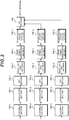
- FIG. 2 is a block diagram showing an outline configuration of a transmission device which transmits a DFT-S-OFDM signal. However, for simplifying a description, FIG. 2 shows the minimum blocks that are needed for describing the present invention. Scramble sections 100-1 to 100-3 carrying out scrambling for the purpose of adding random nature to data, or for the purpose of adding stealth of data thereto. Modulation sections 101-1 to 101-3 perform a modulation such as a QPSK. DFT sections 102-1 to 102-3 perform DFT (Discrete Fourier Transform) on a plurality of pieces of data. DFT may be referred to as DFTPre-Coding.
- DFTPre-Coding DFTPre-Coding.
- Resource map sections 103-1 to 103-3 assign data to a resource block (Resource Block: hereinafter, referred to as "RB") to be used.
- RB is comprised of one or more sub-carriers, and is the smallest unit when a mobile station apparatus accesses a base station apparatus.
- OFDM signal generation sections 104-1 to 104-3 when the RBs to be used are continuous in the resource map sections 103-1 to 103-3, generate a DFT-S-OFDM signal, and on the other hand, when the RBs to be used are non-continuous in the resource map sections 103-1 to 103-3, generate a Clustered DFT-S-OFDM signal. Therefore, in the transmission device shown in FIG. 2 , it becomes possible to switch two access methods, DFT-S-OFDMA and Clustered DFT-S-OFDMA.
- Transmission power control sections 105-1 to 105-3 perform transmission power control in each system frequency band. However, the same function can be realized also in such a manner that the transmission power control sections 105-1 to 105-3 are made to be arranged before IDFT sections (reverse DFT section) incorporated in the OFDM signal generation sections 104-1 to 104-3, and powers for respective sub-carriers are changed.
- IDFT sections reverse DFT section
- the blocks described above are shown by three blocks of 1 to 3 each with hyphen, which is because the CA of FIG. 1 is premised on three system frequency bands .
- An RF section 106 combines inputted three signals, and outputs them to an antenna which is not shown.
- TPC transmission power control
- One is the TPC by a closed loop which controls transmission power based on control information notified from a base station apparatus
- TPC of an open loop which estimates in a mobile station apparatus an attenuation quantity on the basis of a distance or the like from a base station apparatus to control transmission power.
- the OpTx is a transmission power which is determined in every mobile station apparatus
- ClTx is a correction value of a transmission power by a notification from a base station apparatus.
- There is a plurality of notifying methods with respect to the ClTx such as a method of notifying by the difference from the OpTx, a method of accumulating the ClTx notified, and a method of using them together, or the like.
- Min is a function of selecting the smallest value of values shown in the inside of ⁇ .
- the CA is assumed, assumed is a case where scheduling, that is, assignment of RB to a mobile station apparatus, of data is independently performed in a unit of the CA.
- scheduling that is, assignment of RB to a mobile station apparatus
- of data is independently performed in a unit of the CA.
- TxP (cc1) to TxP (cc3) shown by the following formulas are the formulas for determining the transmission powers of the CC1 to CC3 (transmission power control sections 105-1 to 105-3 in FIG. 2 ) in FIG. 1 .
- the OpTx and ClTx are to be a value determined in each CC, and however, this means that it is possible to control independently in consideration of communication characteristic being different in each CC. However, it is not necessary that both the OpTx and ClTx are independent, and the ClTx may have a common value in all CCs.
- an X shown by Min ⁇ X, Y ⁇ may become a negative value. This case means that data cannot be transmitted in the CC.
- a terminal accesses a base station apparatus by frequency division multiplex, and a frequency bandwidth in which the terminal accesses is variable. Therefore, in the case of performing CA, a unit (the number of RBs) where an access is performed does not become the same in each CC essentially. In this case, if the power is assigned preferentially to a CC where the number of RBs to be used is small, an error will occur in a CC where the number of RBs to be used is large, and retransmission will be required. That is, a lot of RBs will be used at a next transmission chance. This can be said to be extremely bad in communication efficiency. Therefore, when the number of RBs is different in each CC, by assigning the power preferentially to communication of the CC where the number of RBs to be used is larger, it becomes possible to perform efficient communication.
- MIMO Multi-Input Multi-Output
- CA carries out scheduling of data independently in each CC
- MIMO is performed or not performed, or Rank of MIMO is different, depending on a CC.
- Rank refers to the number of streams transmitted simultaneously in MIMO transmission.
- the power is assigned preferentially to the CC which performs MIMO rather than the CC which does not perform MIMO.
- the power is assigned preferentially to the CC which performs high-Rank-MIMO transmission.
- the bandwidth of each CC is not necessarily the same.
- a terminal having a plurality of bandwidths uses a CC in accordance with a bandwidth capable of receiving.
- a terminal which can be connected only to the band will be influenced greatly thereby.
- the influence is small in the CC where a system frequency bandwidth is wide. Therefore, by assigning the power preferentially to the transmission performed in the CC where the system frequency bandwidth is narrow, it becomes possible to perform efficient communication.
- priorities there is also a method of determining priorities in descending order of the ratio (transmission bandwidth / system frequency band width) of system frequency bandwidth to transmission bandwidth.
- the retransmission as a method of covering that will become an important technique. If scheduling is independently performed in CCs, a case where the n-th retransmission data and the first time transmission data are transmitted by different CCs simultaneously will be assumed. In this case, by assigning the power preferentially to the CC which transmits the retransmission data rather than the first time transmission data, and among the retransmission data, the retransmission data where n is large, it becomes possible to prevent data from being lost by time-out.
- the transmission power control in each of the system frequency bands on transmission data is performed on the basis of the maximum transmission power of a wireless transmission apparatus, the transmission power can be individually determined in each system frequency band. Thereby, it becomes possible to prevent the throughput of each wireless transmission apparatus and the throughput of the whole wireless area from decreasing. Since the transmission powers of the system frequency bands are determined in descending order of priorities (priority), it is possible to perform broadband communication using a plurality of system frequency bands, while securing the communication performance in the system frequency bands to which the transmission power is assigned preferentially, thus enabling to realize highly efficient communication.
Description
- The present invention relates to a technique for performing wireless carrier aggregation transmission using power control.
- In a wireless communication technique well-known in the art, an uplink (referred to as an up or uplink) generally means a line through which data are transmitted from a mobile station apparatus to a base station apparatus when the base station apparatus and the mobile station apparatus communicate with each other in a cellular communication or the like. In this uplink, the base station apparatus receives signals from various mobile station apparatuses simultaneously. Therefore, if the reception powers are equal, the reception process becomes easy and reception characteristics become also excellent. In order to realize this, a system which controls a transmission power of a signal which a mobile station apparatus transmits has been introduced, which is referred to as transmission power control (TPC: Transmit Power Control).
- A communication system currently used in a mobile phone of 3G (third generation) is CDMA (Code Division Multiple Access), and a plurality of mobile station apparatuses uses different codes, and accesses a base station apparatus simultaneously using the same frequency, and consequently, the TPC which is highly accurate and high-speed is generally needed. On the other hand, in the specification of a next-generation (3.9G) mobile phone, DFT-S-OFDMA (Discrete Fourier Transform-Spread-Orthogonal Frequency Division Multiple Access) is scheduled to be used as a communication system of an uplink, and the highly precise and high-speed TPC like the TPC used in the CDMA is not considered to be necessary. However, for the purpose of controlling appropriately an interference amount to an adjacent base station apparatus, the TPC has been standardized (Non-patent Document 1).
- The TPC method is classified broadly into two types, and one is referred to as an open loop and the other, a closed loop. Performing description briefly assuming that the TPC is used in an uplink, the open loop TPC is one in which a mobile station apparatus controls a transmission power at it's own decision, and the closed loop is one in which a mobile station apparatus controls a transmission power at the direction of a base station apparatus.
- As for the open loop, there is a method which estimates a signal attenuation quantity from the transmission power which a base station apparatus transmits and the reception power which the mobile station apparatus actually receives, and determines the transmission power of the mobile station apparatus from the estimated attenuation quantity and the reception power which is needed at the base station apparatus. On the other hand, as for the closed loop, there is a method which measures a reception power at the base station apparatus and notifies the mobile station apparatus of a shortage/overage, or a method that notifies the mobile station apparatus of an increase/decrease of the transmission power thereof from an error rate of the transmitted signal or the like.
- In addition, as for a next "next generation" (4G), a technique of Carrier Aggregation which uses the systems standardized in the 3. 9G in parallel in a plurality of different bands to make them as one system is investigated. There is a merit that a throughput can be simply improved by this technique.
-
US 2005/135312 A1 discloses determining a maximum power for each carrier in a carrier aggregation system.US 2004/162097 A1 discloses reduction of maximum power according to the number of allocated frequency bands. -
- Non-Patent Document 1: 3gpp ts 36.213 v8.5.0 Chapter 5.1
- Non-Patent Document 2: NOKIA SIEMENS NETWORKS ET AL: "PUSCH Power Control for LTE-Advanced" February 2009 discloses power control using open loop and closed loop components.
- In the 3.9G, a terminal (mobile station) determines a transmission power with a parameter as shown by the following formula.

- In the
Formula 1, the OpTx is a value which each terminal determines on the basis of a propagation path loss or the like from a base station, and the ClTx is a value notified from the base station using control channel or the like. Min {X, Y} is a function which selects the minimum. In the case of 3.9G, a bandwidth which a terminal uses is variable, and therefore, the OpTx is changed also depending on the bandwidth. - On the other hand, as for the Carrier Aggregation which is investigated in the 4G, the plurality of systems standardized in the 3.9G are used. One system of 3.9G which composes the system is referred to as a CC (Component Carrier), and each CC may be controlled independently of each other. In such a system, when a transmission power is determined by the Formula 1, the transmission power may be set at a value near the maximum transmission power. In this case, when a transmission request is made further in other CC, the latter parameter Optx+ClTx of the Formula 1 will exceed the maximum transmission power. Then, since the transmission power is set as the maximum transmission power which is the limit of capacity of the terminal, acquiring of the sufficient transmission power in each CC becomes impossible, and as a result, the reception power in each CC at the base station decreases, and a problem that an error occurs in communication is considered to occur.
- The present invention is made in view of such a situation, and has an object to provide a wireless communication system, wireless transmission apparatus and wireless transmission method capable of preventing an error from occurring in communication even in the case where communication is performed independently in each CC (Component Carrier).
- According to the present invention there is provided a wireless transmission apparatus as defined by
claim 1 and a method as defined by claim 2. - While several embodiments and/or examples have been disclosed in this description, the subject matter for which protection is sought is strictly and solely limited to those embodiments and/ or examples encompassed by the scope of the appended claims. Embodiments and/or examples mentioned in the description that do not fall under the scope of the claims are useful for understanding the invention.
- In this way, since the transmission power control in each of system frequency bands is performed on transmission data, and furthermore, the maximum transmission power which can be transmitted in each system frequency band can be controlled so as to be different from each other, the transmission power can be individually determined in each of the system frequency bands. Thereby, it becomes possible to prevent the throughput of each wireless transmission apparatus and the throughput of the whole wireless area from decreasing.
- (2) In the wireless communications system of the present invention, a priority is set on each of the system frequency bands, and transmission powers of the system frequency bands are determined in descending order of the priorities.
- In this way, since the transmission powers of the system frequency bands are determined in descending order of priorities, broadband communication using a plurality of system frequency bands can be performed while securing the communication performance in the system frequency bands to which the transmission powers are assigned preferentially, and it becomes possible to realize highly efficient communication.
- (3) In the wireless communication system of the present invention, the priority is set in accordance with the bandwidth used for communication in each of the system frequency bands.
- In the case of performing communication using a plurality of system frequency bands, if the transmission power is assigned preferentially to a system frequency band having the small number of RBs (Resource Block) to be used, an error will occur in a system frequency band having the large number of RBs to be used, and retransmission will become necessary. That is, many RBs will be used at a next transmission chance, and communication efficiency will become extremely bad. According to the present invention, since a priority is set in accordance with a bandwidth used for communication in each of system frequency bands, when the number of RBs is different in each of the system frequency bands, for example, by assigning the transmission power preferentially to communication in the system frequency band having the large number of RBs to be used, it becomes possible to perform efficient communication.
- (4) In the wireless communication system of the present invention, the priority is set in accordance with whether MIMO (Multi-Input Multi-Output) communication is performed or not.
- When error correction encoding is performed collectively on each stream in MIMO, that is, the number of code words is one, if an error occurs in a stream transmitted from any of antennas, an error will occur also in all other data, and many data will be lost at one time. According to the present invention, since the priority is set in accordance with whether MIMO communication is performed or not, it becomes possible to perform efficient communication by assigning the transmission power preferentially to a system frequency band which performs MIMO rather than to a system frequency band which does not perform MIMO, for example.
- (5) In the wireless communications system of the present invention, the priority is set in accordance with rank of MIMO.
- When error correction encoding is performed collectively on each stream in MIMO, that is, the number of code words is one, if an error occurs in a stream transmitted from any of antennas, an error will occur also in all other data, and many data will be lost at one time. According to the present invention, since the priority is set in accordance with rank of MIMO, by assigning the transmission power preferentially to a system frequency band which performs high-rank-MIMO, for example, it becomes possible to perform efficient communication.
- (6) In the wireless communications system of the present invention, the priority is set in accordance with a bandwidth of the system frequency band.
- In the case of performing communication using a plurality of system frequency bands, it is assumed that a wireless reception apparatus having a plurality of bandwidths uses any of system frequency bands in accordance with bandwidths capable of receiving. In such a case, if the retransmission occurs because the transmission power is not assigned in the system frequency band having a narrow bandwidth, the wireless reception apparatus which can be connected only to the band will be influenced greatly thereby. According to the present invention, since priorities are set in accordance with bandwidths of system frequency bands, by setting transmission powers in ascending order of bandwidth in system frequency bands, for example, it becomes possible to perform efficient communication.
- (7) In the wireless communication system of the present invention, the priorities are set in accordance with the number of times of retransmission.
- When communication is performed using a plurality of system frequency bands, if scheduling is performed independently among the system frequency bands, a case where the (n-th) retransmission data after plural times of retransmission and the first time transmission data are transmitted by different system frequency bands simultaneously will be assumed. According to the present invention, since priorities are set in accordance with the number of times of retransmission, by prioritizing retransmission data rather than first time transmission data, and by assigning data, among the retransmission data, preferentially to the system frequency band which transmits retransmission data the number of times of retransmission of which is large, it becomes possible to prevent data from being lost by time-out.
- (8) The wireless communication system of the present invention performs the transmission power control on transmission data in each of the system frequency bands, on the basis of a maximum transmission power of the wireless transmission apparatus and the number of system frequency bands used simultaneously.
- Even if PAPR property is good within each system frequency band, by using a plurality of system frequency bands, a problem that PAPR property deteriorates arises like a case where a multi carrier signal is transmitted. According to the present invention, on the basis of the number of system frequency bands used simultaneously as well as the maximum transmission power of the wireless transmission apparatus, the transmission power control on transmission data in each of the system frequency bands is performed, and thereby, it is possible to suppress an influence on the transmission power control caused by change in the property of the communication system.
- (9) The wireless transmission apparatus of the present invention is the one applied to a wireless communication system performing communication using a plurality of system frequency bands, the device comprising: a transmission power control section which performs transmission power control on transmission data in each of the system frequency bands, and sets the maximum transmission powers which are different in each of the frequency bands; and a transmission section which radio-transmits transmission data using the system frequency bands.
- In this way, since the transmission power control on transmission data in each of the system frequency bands is performed, and the maximum transmission powers which are different in each of the frequency bands are set, the transmission power can be individually determined in each system frequency band.
Thereby, it becomes possible to prevent the throughput of each wireless transmission apparatus and the throughput of the whole wireless area from decreasing. - (10) In the wireless transmission apparatus of the present invention, the transmission power control section sets priorities in the respective system frequency bands, and determines transmission powers of the system frequency bands in descending order of the priorities.
- In this way, since the transmission powers of the system frequency bands are determined in descending order of priorities, it is possible to perform broadband communication using a plurality of system frequency bands, while securing the communication performance in the system frequency bands to which the transmission power is assigned preferentially, thus enabling to realize highly efficient communication.
- (11) The wireless transmission method of the present invention is the one of a wireless communication system in which a wireless transmission apparatus and a wireless reception apparatus communicate with each other using a plurality of system frequency bands, the method comprising at least the steps of: performing transmission power control on transmission data in each of the system frequency bands in a transmission power control section; setting maximum transmission powers which are different in each of the system frequency bands; and radio-transmitting transmission data using the system frequency bands in a transmission section.
- In this way, since the transmission power control on transmission data in each of the system frequency bands is performed, and the maximum transmission powers which are different in each of the system frequency bands are set, the transmission power can be individually determined in each system frequency band.
Thereby, it becomes possible to prevent the throughput of each wireless transmission apparatus and the throughput of the whole wireless area from decreasing. - (12) In the wireless transmission method of the present invention, in the step of performing in each of the transmission power control, priorities are set on the respective system frequency bands, and transmission powers of the system frequency bands are determined in descending order of the priorities.
- In this way, since the transmission powers of system frequency bands are determined in descending order of priorities, it is possible to perform broadband communication using a plurality of system frequency bands, while securing the communication performance in the system frequency bands to which the transmission power is assigned preferentially, thus enabling to realize highly efficient communication.
- According to the present invention, since the transmission power control is performed on transmission data in each of the system frequency bands on the basis of the maximum transmission power of a wireless transmission apparatus, the transmission powers can be individually determined in respective system frequency bands. Thereby, it becomes possible to prevent the throughput of each wireless transmission apparatus and the throughput of the whole wireless area from decreasing.
-
-
FIG. 1 is a figure showing a concept of Carrier Aggregation; and -
FIG. 2 is a block diagram showing an outline configuration of a transmission device which transmits a DFT-S-OFDM signal. - Hereinafter, embodiments of the present invention will be described with reference to the drawings. Hereinafter, a description will be given using an uplink through which data are transmitted to a base station apparatus from a mobile station apparatus, which is applicable as a matter of course also to a downlink through which data are transmitted to the mobile station apparatus from the base station apparatus. First, Carrier Aggregation (hereinafter, referred to as "CA") will be described.
FIG. 1 is a figure showing a concept of the CA.FIG. 1 shows a case where three system frequency bands are used performing the CA. Each system frequency band is comprised of a control channel band C and a data channel band D, and the control channel band C is arranged at both ends of the data channel band D. A guard band G is shown between each system frequency band, but is not necessarily needed. Furthermore, a case where a guard band larger than a system frequency band is set also can be assumed. In addition, each system frequency bandwidth, as shown inFIG. 1 , does not need to be the same. There is no problem even if the bandwidths are the same. - In the following embodiments, one system which constitutes the CA is referred to as CC (Component Carrier) , and a frequency band which one CC uses is referred to as a system frequency band.
- A first embodiment is premised on performing CA shown in
FIG. 1 .FIG. 2 is a block diagram showing an outline configuration of a transmission device which transmits a DFT-S-OFDM signal. However, for simplifying a description,FIG. 2 shows the minimum blocks that are needed for describing the present invention. Scramble sections 100-1 to 100-3 carrying out scrambling for the purpose of adding random nature to data, or for the purpose of adding stealth of data thereto. Modulation sections 101-1 to 101-3 perform a modulation such as a QPSK. DFT sections 102-1 to 102-3 perform DFT (Discrete Fourier Transform) on a plurality of pieces of data. DFT may be referred to as DFTPre-Coding. - Resource map sections 103-1 to 103-3 assign data to a resource block (Resource Block: hereinafter, referred to as "RB") to be used. Here, RB is comprised of one or more sub-carriers, and is the smallest unit when a mobile station apparatus accesses a base station apparatus. OFDM signal generation sections 104-1 to 104-3, when the RBs to be used are continuous in the resource map sections 103-1 to 103-3, generate a DFT-S-OFDM signal, and on the other hand, when the RBs to be used are non-continuous in the resource map sections 103-1 to 103-3, generate a Clustered DFT-S-OFDM signal. Therefore, in the transmission device shown in
FIG. 2 , it becomes possible to switch two access methods, DFT-S-OFDMA and Clustered DFT-S-OFDMA. - Transmission power control sections 105-1 to 105-3 perform transmission power control in each system frequency band. However, the same function can be realized also in such a manner that the transmission power control sections 105-1 to 105-3 are made to be arranged before IDFT sections (reverse DFT section) incorporated in the OFDM signal generation sections 104-1 to 104-3, and powers for respective sub-carriers are changed. The blocks described above are shown by three blocks of 1 to 3 each with hyphen, which is because the CA of
FIG. 1 is premised on three system frequency bands . AnRF section 106 combines inputted three signals, and outputs them to an antenna which is not shown. - The transmission power control (hereinafter, referred to as "TPC") is classified broadly into two methods. One is the TPC by a closed loop which controls transmission power based on control information notified from a base station apparatus, and the other is the TPC of an open loop which estimates in a mobile station apparatus an attenuation quantity on the basis of a distance or the like from a base station apparatus to control transmission power. These two kinds of TPC are used together. In order to determine the transmission power, there is a method of using the following formula.

- In the
Formula 1, the OpTx is a transmission power which is determined in every mobile station apparatus, and ClTx is a correction value of a transmission power by a notification from a base station apparatus. There is a plurality of notifying methods with respect to the ClTx, such as a method of notifying by the difference from the OpTx, a method of accumulating the ClTx notified, and a method of using them together, or the like. In theFormula 1, Min is a function of selecting the smallest value of values shown in the inside of {}. - In the system of the invention the CA is assumed, assumed is a case where scheduling, that is, assignment of RB to a mobile station apparatus, of data is independently performed in a unit of the CA. Under such assumption, when a transmission power near the maximum transmission power is being used, if communication is simultaneously started in CCs which are not used heretofore simultaneously, there arise problems such that an error occurs in the data due to rapid shortage of the transmission power, or the transmission power control of the closed loop does not function properly, or the like.
- Then, problems like these are solved by performing the transmission power control independently in each CC, and performing control so that the total transmission power does not exceed the maximum transmission power. TxP (cc1) to TxP (cc3) shown by the following formulas are the formulas for determining the transmission powers of the CC1 to CC3 (transmission power control sections 105-1 to 105-3 in
FIG. 2 ) inFIG. 1 .


- In the Formulas 2 to 4, a, b, c, d, e and f are the constants of 0 or 1, and are determined depending on which CC the power is assigned to preferentially. For example, when priorities are the CC1, the CC2, and the CC3, a=b=d=0 and c=e=f=1. In contrast to the
Formula 1, in the Formulas 2 to 4, the OpTx and ClTx are to be a value determined in each CC, and however, this means that it is possible to control independently in consideration of communication characteristic being different in each CC. However, it is not necessary that both the OpTx and ClTx are independent, and the ClTx may have a common value in all CCs. - In this way, by determining a transmission power independently in each CC, it becomes possible to perform an individual control in a unit of CC, and it becomes possible that a reception level or the like required in a base station apparatus can be set in a unit of CC. For example, in a system where a CC used preferentially in each terminal has been determined, by setting constants of a to f so that the power may be assigned preferentially to the CC, even if transmission requests are simultaneously generated in other CCs, it becomes possible to suppress influence on the CC used preferentially.
- As a result of calculating the transmission power by the Formulas 2 to 4, an X shown by Min {X, Y} may become a negative value. This case means that data cannot be transmitted in the CC.
- In this way, by determining the transmission power in accordance with the priorities of CCs, it is possible to perform broadband communication using a plurality of CCs, while securing the communication performance in the CC to which the transmission power is assigned preferentially, thus enabling to realize highly efficient communication as a result.
- In the first embodiment, shown is a method of determining the transmission power in accordance with priorities of CCs, and, in the present embodiment, a method of determining the priorities and an effect thereof will be described.
- In the 3.9G, a terminal accesses a base station apparatus by frequency division multiplex, and a frequency bandwidth in which the terminal accesses is variable. Therefore, in the case of performing CA, a unit (the number of RBs) where an access is performed does not become the same in each CC essentially. In this case, if the power is assigned preferentially to a CC where the number of RBs to be used is small, an error will occur in a CC where the number of RBs to be used is large, and retransmission will be required. That is, a lot of RBs will be used at a next transmission chance. This can be said to be extremely bad in communication efficiency. Therefore, when the number of RBs is different in each CC, by assigning the power preferentially to communication of the CC where the number of RBs to be used is larger, it becomes possible to perform efficient communication.
- In the next generation and subsequent communication, in order to realize high-speed data transmission even in an uplink, MIMO (Multi-Input Multi-Output) transmission using a plurality of antennas in transmission and reception is expected to be used. When it is considered that the CA carries out scheduling of data independently in each CC, it will be assumed that MIMO is performed or not performed, or Rank of MIMO is different, depending on a CC. Here, "Rank" refers to the number of streams transmitted simultaneously in MIMO transmission. In this case, the power is assigned preferentially to the CC which performs MIMO rather than the CC which does not perform MIMO. In the case where Rank of MIMO differs, the power is assigned preferentially to the CC which performs high-Rank-MIMO transmission. Thereby, it becomes possible to perform more efficient communication.
- In the case of performing error correction encoding collectively for each stream in MIMO (where, the number of code word is one) , if an error occurs in a stream transmitted from any of antennas, an error will occur also in all other data, and many data will be lost at one time. Therefore, by assigning the power preferentially to the CC which performs MIMO rather than the CC which does not MIMO, and the CC where MIMO having higher Rank is used, it is avoidable that data are lost in large quantities.
- As shown also in
FIG. 1 of the first embodiment, in the case of performing CA, the bandwidth of each CC is not necessarily the same. In a system which performs CA, it is assumed that a terminal having a plurality of bandwidths uses a CC in accordance with a bandwidth capable of receiving. In such a case, in the CC where a system frequency bandwidth is narrow, if retransmission occurs due to the power not being assigned, a terminal which can be connected only to the band will be influenced greatly thereby. Meanwhile, the influence is small in the CC where a system frequency bandwidth is wide. Therefore, by assigning the power preferentially to the transmission performed in the CC where the system frequency bandwidth is narrow, it becomes possible to perform efficient communication. For the purpose of determining priorities in detail, there is also a method of determining priorities in descending order of the ratio (transmission bandwidth / system frequency band width) of system frequency bandwidth to transmission bandwidth. - Usually, since the probability that an error will occur in wireless communication compared with cable communication is high, the retransmission as a method of covering that will become an important technique. If scheduling is independently performed in CCs, a case where the n-th retransmission data and the first time transmission data are transmitted by different CCs simultaneously will be assumed. In this case, by assigning the power preferentially to the CC which transmits the retransmission data rather than the first time transmission data, and among the retransmission data, the retransmission data where n is large, it becomes possible to prevent data from being lost by time-out.
- As mentioned above, in the first embodiment to the second embodiment, description has been given by limiting the number of CCs and the communication system. However, without being limited to this, it is also possible to use OFDM as a communication system, for example.
- As described above, according to the embodiments of the present invention, since the transmission power control in each of the system frequency bands on transmission data is performed on the basis of the maximum transmission power of a wireless transmission apparatus, the transmission power can be individually determined in each system frequency band. Thereby, it becomes possible to prevent the throughput of each wireless transmission apparatus and the throughput of the whole wireless area from decreasing. Since the transmission powers of the system frequency bands are determined in descending order of priorities (priority), it is possible to perform broadband communication using a plurality of system frequency bands, while securing the communication performance in the system frequency bands to which the transmission power is assigned preferentially, thus enabling to realize highly efficient communication.
-
- 100-1 to 100-3: SCRAMBLE SECTION
- 101-1 to 101-3: MODULATION SECTION
- 102-1 to 102-3: DFT SECTION
- 103-1 to 103-3: RESOURCE MAP SECTION
- 104-1 to 104-3: OFDM SIGNAL GENERATION SECTION
- 105-1 to 105-3: TRANSMISSION POWER CONTROL SECTION
- 106: RF SECTION
Claims (2)
- A wireless transmission apparatus that performs transmission of transmission data by carrier aggregation using a plurality of system frequency bands, and controlling a transmit power for transmission data for each system frequency band, each of the system frequency bands being comprised of a control channel band (C) and a data channel band (D) , the control channel band (C) being arranged at both ends of the data channel band (D), wherein assignment of resource blocks for transmission data is independently performed for each of the system frequency bands, said apparatus comprising:
a transmit power control section (105) operable to:calculate a difference power for each one of the system frequency bands by subtracting, from a maximum transmit power set for the transmission apparatus, a transmit power of each of the other of the system frequency bands each multiplied by a respective factor, wherein each factor has a value of 0 or 1 depending on which system frequency band is preferentially assigned power, andcontrol the transmit power of each one of the system frequency bands to be the smallest of:the difference power calculated for the respective system frequency band, andthe sum of (i) an open loop transmission power value (OpTx) determined by the wireless transmission apparatus for the respective system frequency band and (ii) a correction value (ClTx) of a transmission power by a notification from a base station apparatus determined for the respective system frequency band. - A method of controlling a transmit power for transmission data for a plurality of system frequency bands, by carrier aggregation, said method comprising:providing each of the system frequency bands with a control channel and a data channel band, wherein the control channel band is arranged at both ends of the data channel band, and wherein assignment of resource blocks for transmission data is independently performed for each of the system frequency bands;calculating a difference power for each one of the system frequency bands by subtracting, from a maximum transmit power set for the transmission apparatus, a transmit power of each of the other of the system frequency bands each multiplied by a respective factor, wherein each factor has a value of 0 or 1 depending on which system frequency band is preferentially assigned power; andcontrolling the transmit power of each one of the system frequency bands to be the smallest of:the difference power calculated for the respective system frequency band, andthe sum of (i) an open loop transmission power value (OpTx) determined by the wireless transmission apparatus for the respective system frequency band and (ii) a correction value (ClTx) of a transmission power by a notification from a base station apparatus determined for the respective system frequency band.
Applications Claiming Priority (2)
| Application Number | Priority Date | Filing Date | Title |
|---|---|---|---|
| JP2009056862 | 2009-03-10 | ||
| PCT/JP2010/050281 WO2010103862A1 (en) | 2009-03-10 | 2010-01-13 | Radio communication system, radio transmission device and radio transmission method |
Publications (3)
| Publication Number | Publication Date |
|---|---|
| EP2408129A1 EP2408129A1 (en) | 2012-01-18 |
| EP2408129A4 EP2408129A4 (en) | 2017-04-26 |
| EP2408129B1 true EP2408129B1 (en) | 2021-05-19 |
Family
ID=42728157
Family Applications (1)
| Application Number | Title | Priority Date | Filing Date |
|---|---|---|---|
| EP10750618.0A Active EP2408129B1 (en) | 2009-03-10 | 2010-01-13 | Radio communication system, radio transmission device and radio transmission method |
Country Status (7)
| Country | Link |
|---|---|
| US (2) | US8717992B2 (en) |
| EP (1) | EP2408129B1 (en) |
| JP (2) | JP5148746B2 (en) |
| KR (1) | KR101616155B1 (en) |
| CN (1) | CN102349253B (en) |
| MX (1) | MX2011009501A (en) |
| WO (1) | WO2010103862A1 (en) |
Families Citing this family (9)
| Publication number | Priority date | Publication date | Assignee | Title |
|---|---|---|---|---|
| TWI495276B (en) * | 2010-05-04 | 2015-08-01 | Realtek Semiconductor Corp | Multi-mode wireless transceiver and multi-mode switching method thereof |
| JP5898087B2 (en) | 2010-11-05 | 2016-04-06 | パナソニック インテレクチュアル プロパティ コーポレーション オブアメリカPanasonic Intellectual Property Corporation of America | Wireless communication terminal apparatus and power allocation method |
| JP5573965B2 (en) * | 2010-12-28 | 2014-08-20 | 富士通株式会社 | Wireless communication system, mobile station, base station, and wireless communication method |
| CN102843759B (en) * | 2011-06-23 | 2016-03-02 | 华为技术有限公司 | A kind of Poewr control method of up multi-input and multi-output channel and subscriber equipment |
| EP2925050A4 (en) * | 2012-11-22 | 2016-07-06 | Sharp Kk | Terminal device |
| US9204467B2 (en) * | 2012-12-11 | 2015-12-01 | Blackberry Limited | Communicating encoded traffic data |
| EP2942897B1 (en) | 2013-01-03 | 2019-03-06 | LG Electronics Inc. | Method and apparatus for transmitting uplink signals in wireless communication system |
| JP2015095688A (en) * | 2013-11-08 | 2015-05-18 | 日本電信電話株式会社 | Multi-carrier transmitter, multi-carrier transmission circuit, and multi-carrier transmission method |
| KR102356971B1 (en) * | 2017-10-18 | 2022-01-28 | 삼성전자주식회사 | Method for data transmissions using carrier aggregation and electronic device thereof |
Family Cites Families (9)
| Publication number | Priority date | Publication date | Assignee | Title |
|---|---|---|---|---|
| US20010034475A1 (en) * | 1995-11-13 | 2001-10-25 | Flach Terry E. | Wireless lan system with cellular architecture |
| US8422434B2 (en) * | 2003-02-18 | 2013-04-16 | Qualcomm Incorporated | Peak-to-average power ratio management for multi-carrier modulation in wireless communication systems |
| US7411930B2 (en) * | 2003-12-17 | 2008-08-12 | Qualcomm, Incorporated | Apparatus and method for prioritized apportionment of transmission power in a multi-carrier terminal |
| US20050201180A1 (en) * | 2004-03-05 | 2005-09-15 | Qualcomm Incorporated | System and methods for back-off and clipping control in wireless communication systems |
| KR101034621B1 (en) * | 2004-08-10 | 2011-05-12 | 엘지전자 주식회사 | Multi Band Mobile Communication Terminal |
| WO2006077696A1 (en) * | 2005-01-18 | 2006-07-27 | Sharp Kabushiki Kaisha | Wireless communication apparatus, mobile terminal and wireless communication method |
| KR101119281B1 (en) * | 2005-08-29 | 2012-03-15 | 삼성전자주식회사 | Apparatus and method of feedback channel quality information and scheduling apparatus and method using thereof in a wireless communication system |
| US8437792B2 (en) * | 2007-02-14 | 2013-05-07 | Qualcomm Incorporated | Uplink power control for LTE |
| JP5014001B2 (en) * | 2007-07-11 | 2012-08-29 | 三菱電機株式会社 | base station |
-
2010
- 2010-01-13 JP JP2011503744A patent/JP5148746B2/en active Active
- 2010-01-13 EP EP10750618.0A patent/EP2408129B1/en active Active
- 2010-01-13 MX MX2011009501A patent/MX2011009501A/en active IP Right Grant
- 2010-01-13 US US13/255,811 patent/US8717992B2/en not_active Expired - Fee Related
- 2010-01-13 WO PCT/JP2010/050281 patent/WO2010103862A1/en active Application Filing
- 2010-01-13 CN CN201080011282.5A patent/CN102349253B/en active Active
- 2010-01-13 KR KR1020117023627A patent/KR101616155B1/en active IP Right Grant
-
2012
- 2012-06-26 JP JP2012143149A patent/JP5575187B2/en active Active
-
2014
- 2014-03-04 US US14/197,040 patent/US9344976B2/en active Active
Non-Patent Citations (2)
| Title |
|---|
| LG ELECTRONICS INC: "RACH Frequency position", 3GPP DRAFT; R1-080915, 3RD GENERATION PARTNERSHIP PROJECT (3GPP), MOBILE COMPETENCE CENTRE ; 650, ROUTE DES LUCIOLES ; F-06921 SOPHIA-ANTIPOLIS CEDEX ; FRANCE, vol. RAN WG1, no. Sorrento, Italy; 20080206, 6 February 2008 (2008-02-06), XP050109388 * |
| TEXAS INSTRUMENTS: "Issues on the choice of Clustered DFT-S-OFDMA versus Nx-SCFDMA", 3GPP DRAFT; R1-083531 TI CLUSTERED VERSUS NX, 3RD GENERATION PARTNERSHIP PROJECT (3GPP), MOBILE COMPETENCE CENTRE ; 650, ROUTE DES LUCIOLES ; F-06921 SOPHIA-ANTIPOLIS CEDEX ; FRANCE, no. Prague, Czech Republic; 20080924, 24 September 2008 (2008-09-24), XP050316895 * |
Also Published As
| Publication number | Publication date |
|---|---|
| MX2011009501A (en) | 2011-09-28 |
| EP2408129A4 (en) | 2017-04-26 |
| JP5148746B2 (en) | 2013-02-20 |
| US8717992B2 (en) | 2014-05-06 |
| WO2010103862A1 (en) | 2010-09-16 |
| JP2012191666A (en) | 2012-10-04 |
| CN102349253A (en) | 2012-02-08 |
| KR101616155B1 (en) | 2016-04-27 |
| EP2408129A1 (en) | 2012-01-18 |
| CN102349253B (en) | 2016-08-17 |
| KR20110136835A (en) | 2011-12-21 |
| US9344976B2 (en) | 2016-05-17 |
| US20120063398A1 (en) | 2012-03-15 |
| JP5575187B2 (en) | 2014-08-20 |
| US20140187229A1 (en) | 2014-07-03 |
| JPWO2010103862A1 (en) | 2012-09-13 |
Similar Documents
| Publication | Publication Date | Title |
|---|---|---|
| EP2408129B1 (en) | Radio communication system, radio transmission device and radio transmission method | |
| US8958376B2 (en) | Scheduling data transmissions between a mobile terminal and a base station in a wireless communications network | |
| KR101427143B1 (en) | Characterization of co-channel interference in a wireless communication system | |
| US11818060B2 (en) | Scheduling data transmissions between a mobile terminal and a base station in a wireless communications network using component carriers | |
| CA3052762A1 (en) | Transmission structures and formats for dl control channels | |
| CN107210882B (en) | Per carrier component signaling for UE capability in a wireless communication system supporting carrier aggregation | |
| US20150036626A1 (en) | Method of grouping users to reduce interference in mimo-based wireless network | |
| WO2007148590A1 (en) | Base station and method in mobile communication system | |
| CN104770040A (en) | Systems and methods for waveform selection and adaptation | |
| EP2890190B1 (en) | Wireless communication system, base station apparatus, mobile station apparatus, and communication method | |
| EP2684414A1 (en) | A radio base station and a method therein for scheduling radio resources | |
| EP3741174B1 (en) | A network node, a wireless communications device and methods therein for accessing an unlicensed radio frequency band | |
| Ahmed et al. | On the group proportional fairness of frequency domain resource allocation in L-SC-FDMA based LTE uplink | |
| EP2116092A1 (en) | Characterization of co-channel interference in a wireless communication system |
Legal Events
| Date | Code | Title | Description |
|---|---|---|---|
| PUAI | Public reference made under article 153(3) epc to a published international application that has entered the european phase |
Free format text: ORIGINAL CODE: 0009012 |
|
| 17P | Request for examination filed |
Effective date: 20110927 |
|
| AK | Designated contracting states |
Kind code of ref document: A1 Designated state(s): AT BE BG CH CY CZ DE DK EE ES FI FR GB GR HR HU IE IS IT LI LT LU LV MC MK MT NL NO PL PT RO SE SI SK SM TR |
|
| DAX | Request for extension of the european patent (deleted) | ||
| RA4 | Supplementary search report drawn up and despatched (corrected) |
Effective date: 20170323 |
|
| RIC1 | Information provided on ipc code assigned before grant |
Ipc: H04W 52/14 20090101ALI20170317BHEP Ipc: H04J 99/00 20090101ALI20170317BHEP Ipc: H04W 52/34 20090101ALI20170317BHEP Ipc: H04W 16/28 20090101ALI20170317BHEP Ipc: H04J 11/00 20060101AFI20170317BHEP Ipc: H04B 7/04 20170101ALI20170317BHEP Ipc: H04B 1/04 20060101ALI20170317BHEP |
|
| STAA | Information on the status of an ep patent application or granted ep patent |
Free format text: STATUS: EXAMINATION IS IN PROGRESS |
|
| 17Q | First examination report despatched |
Effective date: 20180214 |
|
| GRAP | Despatch of communication of intention to grant a patent |
Free format text: ORIGINAL CODE: EPIDOSNIGR1 |
|
| STAA | Information on the status of an ep patent application or granted ep patent |
Free format text: STATUS: GRANT OF PATENT IS INTENDED |
|
| INTG | Intention to grant announced |
Effective date: 20201203 |
|
| GRAS | Grant fee paid |
Free format text: ORIGINAL CODE: EPIDOSNIGR3 |
|
| GRAA | (expected) grant |
Free format text: ORIGINAL CODE: 0009210 |
|
| STAA | Information on the status of an ep patent application or granted ep patent |
Free format text: STATUS: THE PATENT HAS BEEN GRANTED |
|
| AK | Designated contracting states |
Kind code of ref document: B1 Designated state(s): AT BE BG CH CY CZ DE DK EE ES FI FR GB GR HR HU IE IS IT LI LT LU LV MC MK MT NL NO PL PT RO SE SI SK SM TR |
|
| RAP3 | Party data changed (applicant data changed or rights of an application transferred) |
Owner name: SHARP KABUSHIKI KAISHA |
|
| REG | Reference to a national code |
Ref country code: GB Ref legal event code: FG4D |
|
| RIN1 | Information on inventor provided before grant (corrected) |
Inventor name: HAMAGUCHI, YASUHIRO Inventor name: YOKOMAKURA, KAZUNARI Inventor name: NAHAMURA, OSAMU Inventor name: GOTO, JUNGO Inventor name: TAKAHASHI, HIROKI |
|
| REG | Reference to a national code |
Ref country code: CH Ref legal event code: EP |
|
| REG | Reference to a national code |
Ref country code: DE Ref legal event code: R096 Ref document number: 602010066999 Country of ref document: DE |
|
| REG | Reference to a national code |
Ref country code: AT Ref legal event code: REF Ref document number: 1395021 Country of ref document: AT Kind code of ref document: T Effective date: 20210615 |
|
| REG | Reference to a national code |
Ref country code: IE Ref legal event code: FG4D |
|
| REG | Reference to a national code |
Ref country code: LT Ref legal event code: MG9D |
|
| REG | Reference to a national code |
Ref country code: AT Ref legal event code: MK05 Ref document number: 1395021 Country of ref document: AT Kind code of ref document: T Effective date: 20210519 |
|
| REG | Reference to a national code |
Ref country code: NL Ref legal event code: MP Effective date: 20210519 |
|
| PG25 | Lapsed in a contracting state [announced via postgrant information from national office to epo] |
Ref country code: HR Free format text: LAPSE BECAUSE OF FAILURE TO SUBMIT A TRANSLATION OF THE DESCRIPTION OR TO PAY THE FEE WITHIN THE PRESCRIBED TIME-LIMIT Effective date: 20210519 Ref country code: AT Free format text: LAPSE BECAUSE OF FAILURE TO SUBMIT A TRANSLATION OF THE DESCRIPTION OR TO PAY THE FEE WITHIN THE PRESCRIBED TIME-LIMIT Effective date: 20210519 Ref country code: BG Free format text: LAPSE BECAUSE OF FAILURE TO SUBMIT A TRANSLATION OF THE DESCRIPTION OR TO PAY THE FEE WITHIN THE PRESCRIBED TIME-LIMIT Effective date: 20210819 Ref country code: LT Free format text: LAPSE BECAUSE OF FAILURE TO SUBMIT A TRANSLATION OF THE DESCRIPTION OR TO PAY THE FEE WITHIN THE PRESCRIBED TIME-LIMIT Effective date: 20210519 Ref country code: FI Free format text: LAPSE BECAUSE OF FAILURE TO SUBMIT A TRANSLATION OF THE DESCRIPTION OR TO PAY THE FEE WITHIN THE PRESCRIBED TIME-LIMIT Effective date: 20210519 |
|
| PG25 | Lapsed in a contracting state [announced via postgrant information from national office to epo] |
Ref country code: SE Free format text: LAPSE BECAUSE OF FAILURE TO SUBMIT A TRANSLATION OF THE DESCRIPTION OR TO PAY THE FEE WITHIN THE PRESCRIBED TIME-LIMIT Effective date: 20210519 Ref country code: LV Free format text: LAPSE BECAUSE OF FAILURE TO SUBMIT A TRANSLATION OF THE DESCRIPTION OR TO PAY THE FEE WITHIN THE PRESCRIBED TIME-LIMIT Effective date: 20210519 Ref country code: GR Free format text: LAPSE BECAUSE OF FAILURE TO SUBMIT A TRANSLATION OF THE DESCRIPTION OR TO PAY THE FEE WITHIN THE PRESCRIBED TIME-LIMIT Effective date: 20210820 Ref country code: IS Free format text: LAPSE BECAUSE OF FAILURE TO SUBMIT A TRANSLATION OF THE DESCRIPTION OR TO PAY THE FEE WITHIN THE PRESCRIBED TIME-LIMIT Effective date: 20210919 Ref country code: PL Free format text: LAPSE BECAUSE OF FAILURE TO SUBMIT A TRANSLATION OF THE DESCRIPTION OR TO PAY THE FEE WITHIN THE PRESCRIBED TIME-LIMIT Effective date: 20210519 Ref country code: NO Free format text: LAPSE BECAUSE OF FAILURE TO SUBMIT A TRANSLATION OF THE DESCRIPTION OR TO PAY THE FEE WITHIN THE PRESCRIBED TIME-LIMIT Effective date: 20210819 Ref country code: PT Free format text: LAPSE BECAUSE OF FAILURE TO SUBMIT A TRANSLATION OF THE DESCRIPTION OR TO PAY THE FEE WITHIN THE PRESCRIBED TIME-LIMIT Effective date: 20210920 Ref country code: ES Free format text: LAPSE BECAUSE OF FAILURE TO SUBMIT A TRANSLATION OF THE DESCRIPTION OR TO PAY THE FEE WITHIN THE PRESCRIBED TIME-LIMIT Effective date: 20210519 |
|
| PG25 | Lapsed in a contracting state [announced via postgrant information from national office to epo] |
Ref country code: NL Free format text: LAPSE BECAUSE OF FAILURE TO SUBMIT A TRANSLATION OF THE DESCRIPTION OR TO PAY THE FEE WITHIN THE PRESCRIBED TIME-LIMIT Effective date: 20210519 |
|
| PG25 | Lapsed in a contracting state [announced via postgrant information from national office to epo] |
Ref country code: RO Free format text: LAPSE BECAUSE OF FAILURE TO SUBMIT A TRANSLATION OF THE DESCRIPTION OR TO PAY THE FEE WITHIN THE PRESCRIBED TIME-LIMIT Effective date: 20210519 Ref country code: SM Free format text: LAPSE BECAUSE OF FAILURE TO SUBMIT A TRANSLATION OF THE DESCRIPTION OR TO PAY THE FEE WITHIN THE PRESCRIBED TIME-LIMIT Effective date: 20210519 Ref country code: SK Free format text: LAPSE BECAUSE OF FAILURE TO SUBMIT A TRANSLATION OF THE DESCRIPTION OR TO PAY THE FEE WITHIN THE PRESCRIBED TIME-LIMIT Effective date: 20210519 Ref country code: DK Free format text: LAPSE BECAUSE OF FAILURE TO SUBMIT A TRANSLATION OF THE DESCRIPTION OR TO PAY THE FEE WITHIN THE PRESCRIBED TIME-LIMIT Effective date: 20210519 Ref country code: EE Free format text: LAPSE BECAUSE OF FAILURE TO SUBMIT A TRANSLATION OF THE DESCRIPTION OR TO PAY THE FEE WITHIN THE PRESCRIBED TIME-LIMIT Effective date: 20210519 Ref country code: CZ Free format text: LAPSE BECAUSE OF FAILURE TO SUBMIT A TRANSLATION OF THE DESCRIPTION OR TO PAY THE FEE WITHIN THE PRESCRIBED TIME-LIMIT Effective date: 20210519 |
|
| REG | Reference to a national code |
Ref country code: DE Ref legal event code: R097 Ref document number: 602010066999 Country of ref document: DE |
|
| PLBE | No opposition filed within time limit |
Free format text: ORIGINAL CODE: 0009261 |
|
| STAA | Information on the status of an ep patent application or granted ep patent |
Free format text: STATUS: NO OPPOSITION FILED WITHIN TIME LIMIT |
|
| 26N | No opposition filed |
Effective date: 20220222 |
|
| PG25 | Lapsed in a contracting state [announced via postgrant information from national office to epo] |
Ref country code: IS Free format text: LAPSE BECAUSE OF FAILURE TO SUBMIT A TRANSLATION OF THE DESCRIPTION OR TO PAY THE FEE WITHIN THE PRESCRIBED TIME-LIMIT Effective date: 20210919 |
|
| PG25 | Lapsed in a contracting state [announced via postgrant information from national office to epo] |
Ref country code: IT Free format text: LAPSE BECAUSE OF FAILURE TO SUBMIT A TRANSLATION OF THE DESCRIPTION OR TO PAY THE FEE WITHIN THE PRESCRIBED TIME-LIMIT Effective date: 20210519 |
|
| PG25 | Lapsed in a contracting state [announced via postgrant information from national office to epo] |
Ref country code: MC Free format text: LAPSE BECAUSE OF FAILURE TO SUBMIT A TRANSLATION OF THE DESCRIPTION OR TO PAY THE FEE WITHIN THE PRESCRIBED TIME-LIMIT Effective date: 20210519 |
|
| REG | Reference to a national code |
Ref country code: CH Ref legal event code: PL |
|
| REG | Reference to a national code |
Ref country code: BE Ref legal event code: MM Effective date: 20220131 |
|
| PG25 | Lapsed in a contracting state [announced via postgrant information from national office to epo] |
Ref country code: LU Free format text: LAPSE BECAUSE OF NON-PAYMENT OF DUE FEES Effective date: 20220113 |
|
| PG25 | Lapsed in a contracting state [announced via postgrant information from national office to epo] |
Ref country code: BE Free format text: LAPSE BECAUSE OF NON-PAYMENT OF DUE FEES Effective date: 20220131 |
|
| PG25 | Lapsed in a contracting state [announced via postgrant information from national office to epo] |
Ref country code: LI Free format text: LAPSE BECAUSE OF NON-PAYMENT OF DUE FEES Effective date: 20220131 Ref country code: CH Free format text: LAPSE BECAUSE OF NON-PAYMENT OF DUE FEES Effective date: 20220131 |
|
| PG25 | Lapsed in a contracting state [announced via postgrant information from national office to epo] |
Ref country code: IE Free format text: LAPSE BECAUSE OF NON-PAYMENT OF DUE FEES Effective date: 20220113 |
|
| PGFP | Annual fee paid to national office [announced via postgrant information from national office to epo] |
Ref country code: FR Payment date: 20230124 Year of fee payment: 14 |
|
| PGFP | Annual fee paid to national office [announced via postgrant information from national office to epo] |
Ref country code: GB Payment date: 20230119 Year of fee payment: 14 Ref country code: DE Payment date: 20230123 Year of fee payment: 14 |
|
| PG25 | Lapsed in a contracting state [announced via postgrant information from national office to epo] |
Ref country code: HU Free format text: LAPSE BECAUSE OF FAILURE TO SUBMIT A TRANSLATION OF THE DESCRIPTION OR TO PAY THE FEE WITHIN THE PRESCRIBED TIME-LIMIT; INVALID AB INITIO Effective date: 20100113 |