EP2442956B1 - Injection molding tool with core assembly - Google Patents
Injection molding tool with core assembly Download PDFInfo
- Publication number
- EP2442956B1 EP2442956B1 EP10789838.9A EP10789838A EP2442956B1 EP 2442956 B1 EP2442956 B1 EP 2442956B1 EP 10789838 A EP10789838 A EP 10789838A EP 2442956 B1 EP2442956 B1 EP 2442956B1
- Authority
- EP
- European Patent Office
- Prior art keywords
- core assembly
- shaft
- injection molding
- lock
- molding tool
- Prior art date
- Legal status (The legal status is an assumption and is not a legal conclusion. Google has not performed a legal analysis and makes no representation as to the accuracy of the status listed.)
- Not-in-force
Links
- 238000001746 injection moulding Methods 0.000 title claims description 33
- 230000000712 assembly Effects 0.000 description 10
- 238000000429 assembly Methods 0.000 description 10
- 239000004033 plastic Substances 0.000 description 5
- 238000000034 method Methods 0.000 description 4
- 238000002347 injection Methods 0.000 description 2
- 239000007924 injection Substances 0.000 description 2
- 238000003780 insertion Methods 0.000 description 2
- 230000037431 insertion Effects 0.000 description 2
- 238000009434 installation Methods 0.000 description 2
- 239000007769 metal material Substances 0.000 description 2
- 238000000465 moulding Methods 0.000 description 2
- 230000002093 peripheral effect Effects 0.000 description 2
- 239000011800 void material Substances 0.000 description 2
- XLYOFNOQVPJJNP-UHFFFAOYSA-N water Substances O XLYOFNOQVPJJNP-UHFFFAOYSA-N 0.000 description 2
- 238000000071 blow moulding Methods 0.000 description 1
- 238000004512 die casting Methods 0.000 description 1
- 230000005484 gravity Effects 0.000 description 1
- 239000007788 liquid Substances 0.000 description 1
- 238000012423 maintenance Methods 0.000 description 1
- 239000000463 material Substances 0.000 description 1
- 239000002184 metal Substances 0.000 description 1
- 239000002905 metal composite material Substances 0.000 description 1
- 239000002991 molded plastic Substances 0.000 description 1
- 229910052755 nonmetal Inorganic materials 0.000 description 1
Images



Classifications
-
- B—PERFORMING OPERATIONS; TRANSPORTING
- B29—WORKING OF PLASTICS; WORKING OF SUBSTANCES IN A PLASTIC STATE IN GENERAL
- B29C—SHAPING OR JOINING OF PLASTICS; SHAPING OF MATERIAL IN A PLASTIC STATE, NOT OTHERWISE PROVIDED FOR; AFTER-TREATMENT OF THE SHAPED PRODUCTS, e.g. REPAIRING
- B29C45/00—Injection moulding, i.e. forcing the required volume of moulding material through a nozzle into a closed mould; Apparatus therefor
- B29C45/17—Component parts, details or accessories; Auxiliary operations
- B29C45/40—Removing or ejecting moulded articles
- B29C45/44—Removing or ejecting moulded articles for undercut articles
- B29C45/4421—Removing or ejecting moulded articles for undercut articles using expansible or collapsible cores
-
- B—PERFORMING OPERATIONS; TRANSPORTING
- B29—WORKING OF PLASTICS; WORKING OF SUBSTANCES IN A PLASTIC STATE IN GENERAL
- B29C—SHAPING OR JOINING OF PLASTICS; SHAPING OF MATERIAL IN A PLASTIC STATE, NOT OTHERWISE PROVIDED FOR; AFTER-TREATMENT OF THE SHAPED PRODUCTS, e.g. REPAIRING
- B29C33/00—Moulds or cores; Details thereof or accessories therefor
- B29C33/30—Mounting, exchanging or centering
- B29C33/306—Exchangeable mould parts, e.g. cassette moulds, mould inserts
-
- B—PERFORMING OPERATIONS; TRANSPORTING
- B29—WORKING OF PLASTICS; WORKING OF SUBSTANCES IN A PLASTIC STATE IN GENERAL
- B29C—SHAPING OR JOINING OF PLASTICS; SHAPING OF MATERIAL IN A PLASTIC STATE, NOT OTHERWISE PROVIDED FOR; AFTER-TREATMENT OF THE SHAPED PRODUCTS, e.g. REPAIRING
- B29C33/00—Moulds or cores; Details thereof or accessories therefor
- B29C33/44—Moulds or cores; Details thereof or accessories therefor with means for, or specially constructed to facilitate, the removal of articles, e.g. of undercut articles
- B29C33/48—Moulds or cores; Details thereof or accessories therefor with means for, or specially constructed to facilitate, the removal of articles, e.g. of undercut articles with means for collapsing or disassembling
- B29C33/485—Moulds or cores; Details thereof or accessories therefor with means for, or specially constructed to facilitate, the removal of articles, e.g. of undercut articles with means for collapsing or disassembling cores or mandrels
-
- B—PERFORMING OPERATIONS; TRANSPORTING
- B29—WORKING OF PLASTICS; WORKING OF SUBSTANCES IN A PLASTIC STATE IN GENERAL
- B29C—SHAPING OR JOINING OF PLASTICS; SHAPING OF MATERIAL IN A PLASTIC STATE, NOT OTHERWISE PROVIDED FOR; AFTER-TREATMENT OF THE SHAPED PRODUCTS, e.g. REPAIRING
- B29C33/00—Moulds or cores; Details thereof or accessories therefor
- B29C33/76—Cores
-
- B—PERFORMING OPERATIONS; TRANSPORTING
- B29—WORKING OF PLASTICS; WORKING OF SUBSTANCES IN A PLASTIC STATE IN GENERAL
- B29C—SHAPING OR JOINING OF PLASTICS; SHAPING OF MATERIAL IN A PLASTIC STATE, NOT OTHERWISE PROVIDED FOR; AFTER-TREATMENT OF THE SHAPED PRODUCTS, e.g. REPAIRING
- B29C45/00—Injection moulding, i.e. forcing the required volume of moulding material through a nozzle into a closed mould; Apparatus therefor
- B29C45/17—Component parts, details or accessories; Auxiliary operations
- B29C45/26—Moulds
- B29C45/2673—Moulds with exchangeable mould parts, e.g. cassette moulds
- B29C45/2675—Mounting of exchangeable mould inserts
-
- B—PERFORMING OPERATIONS; TRANSPORTING
- B29—WORKING OF PLASTICS; WORKING OF SUBSTANCES IN A PLASTIC STATE IN GENERAL
- B29C—SHAPING OR JOINING OF PLASTICS; SHAPING OF MATERIAL IN A PLASTIC STATE, NOT OTHERWISE PROVIDED FOR; AFTER-TREATMENT OF THE SHAPED PRODUCTS, e.g. REPAIRING
- B29C45/00—Injection moulding, i.e. forcing the required volume of moulding material through a nozzle into a closed mould; Apparatus therefor
- B29C45/17—Component parts, details or accessories; Auxiliary operations
- B29C45/26—Moulds
- B29C45/33—Moulds having transversely, e.g. radially, movable mould parts
- B29C45/332—Mountings or guides therefor; Drives therefor
-
- B—PERFORMING OPERATIONS; TRANSPORTING
- B29—WORKING OF PLASTICS; WORKING OF SUBSTANCES IN A PLASTIC STATE IN GENERAL
- B29C—SHAPING OR JOINING OF PLASTICS; SHAPING OF MATERIAL IN A PLASTIC STATE, NOT OTHERWISE PROVIDED FOR; AFTER-TREATMENT OF THE SHAPED PRODUCTS, e.g. REPAIRING
- B29C45/00—Injection moulding, i.e. forcing the required volume of moulding material through a nozzle into a closed mould; Apparatus therefor
- B29C45/17—Component parts, details or accessories; Auxiliary operations
- B29C45/26—Moulds
- B29C45/36—Moulds having means for locating or centering cores
-
- F—MECHANICAL ENGINEERING; LIGHTING; HEATING; WEAPONS; BLASTING
- F16—ENGINEERING ELEMENTS AND UNITS; GENERAL MEASURES FOR PRODUCING AND MAINTAINING EFFECTIVE FUNCTIONING OF MACHINES OR INSTALLATIONS; THERMAL INSULATION IN GENERAL
- F16B—DEVICES FOR FASTENING OR SECURING CONSTRUCTIONAL ELEMENTS OR MACHINE PARTS TOGETHER, e.g. NAILS, BOLTS, CIRCLIPS, CLAMPS, CLIPS OR WEDGES; JOINTS OR JOINTING
- F16B21/00—Means for preventing relative axial movement of a pin, spigot, shaft or the like and a member surrounding it; Stud-and-socket releasable fastenings
- F16B21/02—Releasable fastening devices locking by rotation
- F16B21/04—Releasable fastening devices locking by rotation with bayonet catch
-
- B—PERFORMING OPERATIONS; TRANSPORTING
- B29—WORKING OF PLASTICS; WORKING OF SUBSTANCES IN A PLASTIC STATE IN GENERAL
- B29L—INDEXING SCHEME ASSOCIATED WITH SUBCLASS B29C, RELATING TO PARTICULAR ARTICLES
- B29L2031/00—Other particular articles
- B29L2031/56—Stoppers or lids for bottles, jars, or the like, e.g. closures
-
- Y—GENERAL TAGGING OF NEW TECHNOLOGICAL DEVELOPMENTS; GENERAL TAGGING OF CROSS-SECTIONAL TECHNOLOGIES SPANNING OVER SEVERAL SECTIONS OF THE IPC; TECHNICAL SUBJECTS COVERED BY FORMER USPC CROSS-REFERENCE ART COLLECTIONS [XRACs] AND DIGESTS
- Y10—TECHNICAL SUBJECTS COVERED BY FORMER USPC
- Y10S—TECHNICAL SUBJECTS COVERED BY FORMER USPC CROSS-REFERENCE ART COLLECTIONS [XRACs] AND DIGESTS
- Y10S425/00—Plastic article or earthenware shaping or treating: apparatus
- Y10S425/058—Undercut
Definitions
- This invention relates to an injection molding tool having a core assembly, such as a collapsible core assembly or an expandable cavity assembly, for quick and easy installation and removal.
- a core assembly such as a collapsible core assembly or an expandable cavity assembly
- Conventional core assemblies such as expandable cavity elements and collapsible core assemblies are known and have been used with injection molding tools.
- Known collapsible core assemblies use segments that slide or otherwise move with respect to each other to vary the outer diameter of the core assembly.
- Core assemblies are often used with stripper plates or movable plates to guide movement of and to hold the core assembly in position during one or more steps of an injection molding process. After a plastic part or article is injection molded, the core assembly can either collapse or expand to release or otherwise discharge the molded part or article.
- US 2009/0061043 A1 discloses a mold insert retaining structure having a retainer plate which is secured to a mold with spring-loaded bolts to fix the retainer plate resiliently. This facilitates insertion and removal of the mold insert.
- JP H04 367350 A which also discloses a cylindrical fitting hole in a master die in which a core is fitted by rotation thereof.
- US 2009/0061043 A1 discloses a mold insert retaining structure having a retainer plate which is secured to a mold with spring-loaded bolts to fix the retainer plate resiliently. This facilitates insertion and removal of the mold insert.
- JP H04 367350 A which also discloses a cylindrical fitting hole in a master die in which a core is fitted by rotation thereof.
- An injection molding tool of this invention can be used to secure or otherwise prevent movement of a core assembly within the injection molding tool.
- a guide ring assembly having at least a portion of a passage with a non-circular periphery can be used to prevent rotational movement of the core assembly with respect to the guide ring assembly and thus a mold plate.
- a dovetail type collapsible core assembly has a central section, a pin, and slides or sliding segments.
- the slides can move with respect to the central section to collapse the core assembly and allow discharge of a molded plastic part or other article produced using an injection molding tool.
- Grooves within the central pin can be positioned at an angle with respect to a longitudinal axis of the central pin, and can be shaped to accommodate the corresponding slides or other guiding elements.
- the slides can be sized and shaped differently to accommodate different types of movements, depending upon the particular part or other article produced by the injection molding tool. Shapes, angles and/or sizes of the elements can be varied to achieve different movements or rates of movements of elements of the collapsible core assembly.
- An injection molding tool can be used to quickly access a collapsible core, for installation and/or removal.
- This invention can be used to reduce or minimize labor associated with core assembly maintenance.
- This invention can be used to prevent movement of the core assembly in a rotational direction with respect to a guide ring assembly or a clamshell assembly.
- the guide ring assembly can have grooves or other tracks or guides within one or more rings, to prevent the slides or other guide segments from twisting in an expanded position and/or from falling due to gravity in a collapsed position.
- This invention can also be used to prevent or otherwise limit rotational or polar movement of the core assembly with respect to the guide ring assembly. This particular feature can be used to orient the injection molding tool to produce a plastic part or other article in a specific and repeated position.
- the lock can be used to quickly assemble or disassemble the central pin and thus the core assembly.
- Bolts or other suitable fasteners can be used to secure the lock with respect to the guide ring assembly and/or the mold plates.
- a shaft is sized and shaped to be passable through a corresponding bore of the lock.
- the lock can be rotated with respect to the shaft in order to secure the lock with respect to the shaft.
- the lock can be used to secure many different types of conventional collapsible core assemblies.
- the guide ring assembly of this invention can be used to prevent rotational or pivotal movement of the core assembly with respect to the guide ring assembly.
- Figs. 1-11 show different embodiments of injection molding tool 20 according to this invention.
- injection molding tool is intended to relate to and include any apparatus and/or process in which plastic, metal and/or another suitable material flows under pressure into a mold cavity or other similar tool structure.
- a collapsible core can be used to form or define internal details or features of a plastic part or article.
- the plastic part can be formed around or about an expanded collapsible core. After the part is formed, the core collapses inward or upon itself to release a shoulder, a thread or an undercut, for example, so that the part can be removed or discharged from the tool.
- Collapsible core assemblies have been used not only with injection molding but also with die casting, blow molding, rotor molding and other similar molding processes.
- Figs. 1-6 show different embodiments of elements of core assembly 39, of this invention.
- core assembly 39 comprises shaft 40 having end 42.
- Fig. 5 shows shaft 40 also forming groove 41.
- groove 41 has a generally rectangular cross-section, about a periphery of shaft 40.
- groove 41 can have any other suitable cross-section or shape.
- end 42 forms contact surface 44, which may or may not have a ramp surface.
- contact surface 44 and/or groove 41 of end 42 can have any other suitable shape and/or dimension.
- Injection molding tool 20 of this invention also comprises lock 50 that is moveable with respect to shaft 40, for securing lock 50 with respect to shaft 40.
- lock 50 is rotated with respect to shaft 40 to secure shaft 40 and thus core assembly 39, in an axial direction
- Figs. 9-11 show one embodiment of shaft 40 and lock 50 and how they cooperate with each other to secure lock 50 with respect to shaft 40 and thus core assembly 39.
- end 42 of shaft 40 is inserted in the direction of the arrow into bore 52 of lock 50.
- Fig. 10 shows one position of end 42 inserted within bore 52 and then rotated in the direction of the arcuate arrow shown in Fig. 10 , for example, to secure or lock the position of lock 50 with respect to shaft 40.
- Fig. 1 1 shows a bottom view of end 42 securedly mounted within bore 52.
- a ramp surface on contact surface 44 and/or on surface 53 of plate 51 is used to translate the rotational movement of lock 50 with respect to shaft 40 into axial movement of shaft 40, for example with respect to a mold plate, such as plate 24 shown in Fig. 7 .
- ramp 54 can be cut into and/or otherwise formed on plate 51.
- lock 50 comprises or is shaped as plate 51.
- lock 50 and/or end 42 of shaft 40 can have any other suitable structural shape, dimension and/or design used to accomplish the rotational movement of lock 50 with respect to shaft 40, and to result in axial movement of shaft 40 and thus of core assembly 39 with respect to a mold plate, such as plate 24 shown in Fig. 7 .
- Fig. 9 shows plate 51 of lock 50 having non-circular bore 52. So that end 42 of shaft 40 can be positioned within bore 52 of lock 50, which movement for example is shown from Fig. 9 to Fig. 10 , end 42 can have a corresponding non-circular shape.
- end 42 can have but does not necessarily require a peripheral shape that corresponds to or matches the peripheral shape of bore 52.
- end 42 is slightly smaller than bore 52, so that end 42 can pass through bore 52, such as shown in the position of Fig. 10 .
- End 42 and/or bore 52 can have any other suitable shape, as long as end 42 has a cross section or overall shape that is passable through non-circular bore 52.
- end 42 can have a shape that does not correspond to or that is not similar to bore 52.
- end 42 when lock 50 is rotated with respect to shaft 40 the mechanical engagement between them, translates the rotational movement of lock 50 with respect to shaft 40 into axial movement of shaft 40 and thus core assembly 39 with respect to a mold plate, such as plate 24 as shown in Fig. 7 .
- bore 52 can be a closed bore rather than the open bore such as shown in Fig. 9 .
- a closed bore can be shaped and/or sized to still accommodate the desired locking movement or engagement between lock 50 and shaft 40.
- Figs. 9 and 11 show plate 51 of lock 50 having at least one bore 55, which can be used to accommodate a bolt or other fastener to secure lock 50 with respect to retainer plate 25 or another suitable mold plate of injection molding tool 20.
- core assembly 39 further comprises guide ring assembly 31 that has a central passage through which shaft 40 and/or pin 45 passes.
- plate 51 of lock 50 is positioned between retainer plate 25 and plate 27 of injection molding tool 20. The movement of lock 50 with respect to shaft 40 secures or otherwise locks the axial position of core assembly 39.
- locking or securing the axial movement can be used to apply forces required to seal O-ring 60 with respect to shaft 40 and/or mold plate 27.
- O-ring 60 is used to seal a water line or another liquid supply line for core assembly 39.
- Fig. 8 shows an enlarged view of lock 50 formed as plate 51.
- Fig. 8 shows plate 51 in a sectional view.
- Plate section 51 A is shown having a same horizontal dimension but a greater vertical dimension as compared to plate section 5 IB.
- plate section 51 A has a two-dimensional area which is greater than a two-dimensional area of plate section 5 IB.
- the arrangement shown in Fig. 8 is used to create a ramp on surface 53.
- the ramp translates the rotational movement into vertical movement of shaft 40 and/or into vertical forces applied to shaft 40.
- the vertical forces can be used to seal O-ring 60.
- plate 51 and/or lock 50 can have a shape and/or dimension different than as shown in Fig. 8 and still accomplish the desired result of translating rotational or other suitable movement of lock 50 with respect to shaft 40 into axial movement of and/or into axial forces applied to shaft 40.
- O-ring 60 there is no need for O-ring 60, for example, because water lines or other pressurized lines are not necessary or required for the particular use of injection molding tool 20.
- injection molding tool 20 comprises guide ring assembly 31, which can also be referred to as a clamshell assembly.
- Guide ring assembly 31 forms a central passage through which core assembly 39 passes, such as shown in Fig. 7 .
- Figs. 1-3 show guide ring assembly 31 comprising center ring 32 positioned between or sandwiched between outer ring 36 and outer ring 37.
- Fig. 6 shows an exploded perspective view of guide ring assembly 31, according to certain embodiments of this invention.
- Fig. 6 shows center ring 32 having non-circular bore 33.
- the non-circular periphery of bore 33 can be used to prevent or otherwise limit rotational or polar movement of core assembly 39 with respect to center ring 32, outer ring 36 and/or outer ring 37.
- lock 50 can also be used to prevent a similar rotational movement
- the non-circular shape of bore 33 can be used along with or in place of lock 50 to prevent rotational movement of core assembly 39 within guide ring assembly 31.
- outer ring 36 is secured with respect to a mold plate, such as plate 24 as shown in Fig. 7 , rotational movement of core assembly 39 can be prevented or otherwise limited, with respect to plate 24.
- Any suitable surface of core assembly 39 for example can engage with or otherwise contact a surface of center ring 32 to limit or prevent rotation or other movement of core assembly 39 about longitudinal axis 47 of core assembly 39.
- center ring 33 comprises at least one guide channel 34 and at least one smaller guide channel 35, which are positioned about a periphery of bore 33.
- Fig. 6 shows center ring 32 having three guide channels 34 and three guide channels 35, in alternating arrangement about the periphery of bore 33.
- guide ring assembly requires only one void or other structure, such as guide channel 34 or guide channel 35.
- center ring 32 has between about 4 and about 12 total guide channels 34 and/or 35.
- core assembly 39 comprises pin 45 that forms at least one dovetail groove 48.
- Fig. 6 also shows differently shaped sliding elements or slides 49 that have dovetail portions that engage or mate within a corresponding groove 48.
- core assembly 39 comprises three larger slides 49 and three smaller slides 49.
- Each slide 49 can be fixed in position with respect to plate 24, such as shown in Fig. 7 , for example by mounting or engaging flange 46 within a corresponding void formed by guide ring assembly 31 , as shown in Fig. 7 .
- stripper plate 23 can be positioned as shown in Fig. 7 .
- non-circular bore 33 of center ring 32 can be formed in any other suitable shape.
- any corresponding element of core assembly 39 can be sized and/or shaped differently to provide different opening and/or closing movements which may be required by any suitable use of injection molding tool 20 according to this invention.
- lock 50 is used in combination with center ring 32 having non-circular bore 33.
- lock 50 or center ring 32 with non-circular bore 33 can be used independent of each other, particularly when used with other conventional and suitable collapsible core assemblies or expandable cavity assemblies.
- the elements of this invention can be manufactured using any metal material, any non-metal material and/or composite material.
Landscapes
- Engineering & Computer Science (AREA)
- Mechanical Engineering (AREA)
- Manufacturing & Machinery (AREA)
- General Engineering & Computer Science (AREA)
- Moulds For Moulding Plastics Or The Like (AREA)
- Injection Moulding Of Plastics Or The Like (AREA)
Description
- This invention relates to an injection molding tool having a core assembly, such as a collapsible core assembly or an expandable cavity assembly, for quick and easy installation and removal.
- Conventional core assemblies, such as expandable cavity elements and collapsible core assemblies are known and have been used with injection molding tools. Known collapsible core assemblies use segments that slide or otherwise move with respect to each other to vary the outer diameter of the core assembly.
- Core assemblies are often used with stripper plates or movable plates to guide movement of and to hold the core assembly in position during one or more steps of an injection molding process. After a plastic part or article is injection molded, the core assembly can either collapse or expand to release or otherwise discharge the molded part or article.
- Many conventional injection molding systems use mold plates that are moveably and/or fixedly with respect to each other, some of which are grouped together, to accomplish movement between an injection mold step of the process and an article release step of the process. A driver or another suitable mechanical system can be used to move and/or fix any one or more of the mold plates with respect to each other and/or to the core assembly. Because many conventional injection molding systems use collapsible core assemblies or expandible core assemblies, there is an apparent need to quickly and cost-efficiently install, remove and/or otherwise maintain the core assembly and/or other connected or related elements.
-
US 2009/0061043 A1 discloses a mold insert retaining structure having a retainer plate which is secured to a mold with spring-loaded bolts to fix the retainer plate resiliently. This facilitates insertion and removal of the mold insert. -
US 5,352,398 A ,US 4,150,931 A andJP 2004/351853 A - Further reference is made to
JP H04 367350 A -
US 2009/0061043 A1 discloses a mold insert retaining structure having a retainer plate which is secured to a mold with spring-loaded bolts to fix the retainer plate resiliently. This facilitates insertion and removal of the mold insert. -
US 5,352 ,398 A ,US 4,150,931 A andJP 2004/351853 A - Further reference is made to
JP H04 367350 A - An injection molding tool of this invention can be used to secure or otherwise prevent movement of a core assembly within the injection molding tool. A guide ring assembly having at least a portion of a passage with a non-circular periphery can be used to prevent rotational movement of the core assembly with respect to the guide ring assembly and thus a mold plate.
- In some embodiments of this invention, a dovetail type collapsible core assembly has a central section, a pin, and slides or sliding segments. The slides can move with respect to the central section to collapse the core assembly and allow discharge of a molded plastic part or other article produced using an injection molding tool. Grooves within the central pin can be positioned at an angle with respect to a longitudinal axis of the central pin, and can be shaped to accommodate the corresponding slides or other guiding elements.
- The slides can be sized and shaped differently to accommodate different types of movements, depending upon the particular part or other article produced by the injection molding tool. Shapes, angles and/or sizes of the elements can be varied to achieve different movements or rates of movements of elements of the collapsible core assembly.
- An injection molding tool according to this invention can be used to quickly access a collapsible core, for installation and/or removal. This invention can be used to reduce or minimize labor associated with core assembly maintenance. This invention can be used to prevent movement of the core assembly in a rotational direction with respect to a guide ring assembly or a clamshell assembly. The guide ring assembly can have grooves or other tracks or guides within one or more rings, to prevent the slides or other guide segments from twisting in an expanded position and/or from falling due to gravity in a collapsed position. This invention can also be used to prevent or otherwise limit rotational or polar movement of the core assembly with respect to the guide ring assembly. This particular feature can be used to orient the injection molding tool to produce a plastic part or other article in a specific and repeated position. The lock can be used to quickly assemble or disassemble the central pin and thus the core assembly. Bolts or other suitable fasteners can be used to secure the lock with respect to the guide ring assembly and/or the mold plates. According to this invention, a shaft is sized and shaped to be passable through a corresponding bore of the lock. The lock can be rotated with respect to the shaft in order to secure the lock with respect to the shaft. In some embodiments of this invention, the lock can be used to secure many different types of conventional collapsible core assemblies. Likewise, the guide ring assembly of this invention can be used to prevent rotational or pivotal movement of the core assembly with respect to the guide ring assembly.
- Different exemplary embodiments of the subject matter of this invention are described below in view of the attached drawings, wherein:
-
Fig. 1 is a perspective view of a core assembly mounted within a guide ring assembly, -
Fig. 2 is a front view of the core assembly and the guide ring assembly, as shown inFig. 1 ; -
Fig. 3 is a side view of the core assembly and the guide ring assembly, as shown inFig. 1 ; -
Fig. 4 is a top view of the core assembly and the guide ring assembly, as shown inFig. 1 ; -
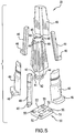
Fig. 5 is an exploded perspective view of a core assembly, according to one embodiment of this invention; -
Fig. 6 is an enlarged view of a guide ring assembly, according to one embodiment of this invention; -
Fig. 7 is a partial cross-sectional view of a core assembly and a guide ring assembly mounted within an injection molding tool, according to one embodiment of this invention; -
Fig. 8 is an exploded cross-sectional view of a lock mounted within an injection molding tool, according to one embodiment of this invention; -
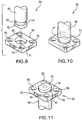
Fig. 9 is an exploded perspective top view of a shaft and a lock, in an unassembled position, according to one embodiment of this invention; -
Fig. 10 is a top perspective view of the shaft and the lock, in an assembled position, according to the embodiment as shown inFig. 9 ; and -
Fig. 11 is a perspective bottom view of a shaft and a lock, in an assembled position, according to one embodiment of this invention. -
Figs. 1-11 show different embodiments ofinjection molding tool 20 according to this invention. As used throughout this specification and in the claims, the term injection molding tool is intended to relate to and include any apparatus and/or process in which plastic, metal and/or another suitable material flows under pressure into a mold cavity or other similar tool structure. - Conventional mechanical collapsing cores have been used in injection molding tools. With injection molding processes, a collapsible core can be used to form or define internal details or features of a plastic part or article. The plastic part can be formed around or about an expanded collapsible core. After the part is formed, the core collapses inward or upon itself to release a shoulder, a thread or an undercut, for example, so that the part can be removed or discharged from the tool. Collapsible core assemblies have been used not only with injection molding but also with die casting, blow molding, rotor molding and other similar molding processes.
-
Figs. 1-6 show different embodiments of elements ofcore assembly 39, of this invention. As shown inFigs. 2, 3 and5 , for example,core assembly 39 comprisesshaft 40 havingend 42.Fig. 5 showsshaft 40 also forminggroove 41. As shown inFigs. 5 and7 ,groove 41 has a generally rectangular cross-section, about a periphery ofshaft 40. However,groove 41 can have any other suitable cross-section or shape. As shown inFig. 5 ,end 42forms contact surface 44, which may or may not have a ramp surface. Depending upon the desired engagement to or contact withlock 50,contact surface 44 and/or groove 41 ofend 42 can have any other suitable shape and/or dimension. -
Injection molding tool 20 of this invention also compriseslock 50 that is moveable with respect toshaft 40, for securinglock 50 with respect toshaft 40. According to this invention, lock 50 is rotated with respect toshaft 40 to secureshaft 40 and thuscore assembly 39, in an axial direction -
Figs. 9-11 show one embodiment ofshaft 40 andlock 50 and how they cooperate with each other to securelock 50 with respect toshaft 40 and thuscore assembly 39. As shown inFig. 9 , end 42 ofshaft 40 is inserted in the direction of the arrow intobore 52 oflock 50.Fig. 10 shows one position ofend 42 inserted withinbore 52 and then rotated in the direction of the arcuate arrow shown inFig. 10 , for example, to secure or lock the position oflock 50 with respect toshaft 40.Fig. 1 1 shows a bottom view ofend 42 securedly mounted withinbore 52. - According to this invention, when
lock 50 is rotated with respect toshaft 40, a ramp surface oncontact surface 44 and/or onsurface 53 ofplate 51 is used to translate the rotational movement oflock 50 with respect toshaft 40 into axial movement ofshaft 40, for example with respect to a mold plate, such asplate 24 shown inFig. 7 . - As shown in
Fig. 11 ,ramp 54 can be cut into and/or otherwise formed onplate 51. - As shown in
Figs. 1-4 and9-11 ,lock 50 comprises or is shaped asplate 51. However, in other embodiments, lock 50 and/or end 42 ofshaft 40 can have any other suitable structural shape, dimension and/or design used to accomplish the rotational movement oflock 50 with respect toshaft 40, and to result in axial movement ofshaft 40 and thus ofcore assembly 39 with respect to a mold plate, such asplate 24 shown inFig. 7 . -
Fig. 9 showsplate 51 oflock 50 havingnon-circular bore 52. So thatend 42 ofshaft 40 can be positioned withinbore 52 oflock 50, which movement for example is shown fromFig. 9 to Fig. 10 , end 42 can have a corresponding non-circular shape. For example, end 42 can have but does not necessarily require a peripheral shape that corresponds to or matches the peripheral shape ofbore 52. In some embodiments according to this invention, end 42 is slightly smaller than bore 52, so thatend 42 can pass throughbore 52, such as shown in the position ofFig. 10 .End 42 and/or bore 52 can have any other suitable shape, as long asend 42 has a cross section or overall shape that is passable throughnon-circular bore 52. - In other embodiments according to this invention, end 42 can have a shape that does not correspond to or that is not similar to bore 52. In some embodiments of this invention, with the selected shape and/or dimension of
end 42, whenlock 50 is rotated with respect toshaft 40 the mechanical engagement between them, translates the rotational movement oflock 50 with respect toshaft 40 into axial movement ofshaft 40 and thuscore assembly 39 with respect to a mold plate, such asplate 24 as shown inFig. 7 . In other embodiments according to this invention, bore 52 can be a closed bore rather than the open bore such as shown inFig. 9 . A closed bore can be shaped and/or sized to still accommodate the desired locking movement or engagement betweenlock 50 andshaft 40. -
Figs. 9 and 11 show plate 51 oflock 50 having at least one bore 55, which can be used to accommodate a bolt or other fastener to securelock 50 with respect toretainer plate 25 or another suitable mold plate ofinjection molding tool 20. - As shown in
Figs. 1-4 , for example,core assembly 39 further comprisesguide ring assembly 31 that has a central passage through whichshaft 40 and/or pin 45 passes. According to one embodiment as shown inFig. 7 ,plate 51 oflock 50 is positioned betweenretainer plate 25 andplate 27 ofinjection molding tool 20. The movement oflock 50 with respect toshaft 40 secures or otherwise locks the axial position ofcore assembly 39. As shown inFig. 7 , locking or securing the axial movement can be used to apply forces required to seal O-ring 60 with respect toshaft 40 and/ormold plate 27. In some embodiments according to this invention, O-ring 60 is used to seal a water line or another liquid supply line forcore assembly 39. -
Fig. 8 shows an enlarged view oflock 50 formed asplate 51.Fig. 8 showsplate 51 in a sectional view.Plate section 51 A is shown having a same horizontal dimension but a greater vertical dimension as compared to plate section 5 IB. Thus, as shown inFig. 8 ,plate section 51 A has a two-dimensional area which is greater than a two-dimensional area of plate section 5 IB. The arrangement shown inFig. 8 is used to create a ramp onsurface 53. Thus, asplate 51 is rotated aboutshaft 40, the ramp translates the rotational movement into vertical movement ofshaft 40 and/or into vertical forces applied toshaft 40. The vertical forces can be used to seal O-ring 60. In other embodiments according to this invention,plate 51 and/or lock 50 can have a shape and/or dimension different than as shown inFig. 8 and still accomplish the desired result of translating rotational or other suitable movement oflock 50 with respect toshaft 40 into axial movement of and/or into axial forces applied toshaft 40. - In some embodiments according to this invention, there is no need for O-
ring 60, for example, because water lines or other pressurized lines are not necessary or required for the particular use ofinjection molding tool 20. - According to some embodiments of this invention, for example as shown in
Figs. 1-4 ,injection molding tool 20 comprisesguide ring assembly 31, which can also be referred to as a clamshell assembly.Guide ring assembly 31 forms a central passage through whichcore assembly 39 passes, such as shown inFig. 7 .Figs. 1-3 showguide ring assembly 31 comprisingcenter ring 32 positioned between or sandwiched betweenouter ring 36 andouter ring 37. -
Fig. 6 shows an exploded perspective view ofguide ring assembly 31, according to certain embodiments of this invention.Fig. 6 showscenter ring 32 havingnon-circular bore 33. The non-circular periphery ofbore 33 can be used to prevent or otherwise limit rotational or polar movement ofcore assembly 39 with respect tocenter ring 32,outer ring 36 and/orouter ring 37. Althoughlock 50 can also be used to prevent a similar rotational movement, the non-circular shape ofbore 33 can be used along with or in place oflock 50 to prevent rotational movement ofcore assembly 39 withinguide ring assembly 31. Becauseouter ring 36 is secured with respect to a mold plate, such asplate 24 as shown inFig. 7 , rotational movement ofcore assembly 39 can be prevented or otherwise limited, with respect toplate 24. Any suitable surface ofcore assembly 39, for example can engage with or otherwise contact a surface ofcenter ring 32 to limit or prevent rotation or other movement ofcore assembly 39 aboutlongitudinal axis 47 ofcore assembly 39. - As shown in
Fig. 6 ,center ring 33 comprises at least oneguide channel 34 and at least onesmaller guide channel 35, which are positioned about a periphery ofbore 33.Fig. 6 showscenter ring 32 having threeguide channels 34 and threeguide channels 35, in alternating arrangement about the periphery ofbore 33. In order to form a non- circular periphery ofbore 33, guide ring assembly requires only one void or other structure, such asguide channel 34 or guidechannel 35. In some embodiments according to this invention,center ring 32 has between about 4 and about 12total guide channels 34 and/or 35. - As shown in
Fig. 5 ,core assembly 39 comprisespin 45 that forms at least onedovetail groove 48.Fig. 6 also shows differently shaped sliding elements or slides 49 that have dovetail portions that engage or mate within a correspondinggroove 48. As shown inFig. 5 , according to some embodiments of this invention,core assembly 39 comprises threelarger slides 49 and threesmaller slides 49. Eachslide 49 can be fixed in position with respect toplate 24, such as shown inFig. 7 , for example by mounting or engagingflange 46 within a corresponding void formed byguide ring assembly 31 , as shown inFig. 7 . In some embodiments of this invention,stripper plate 23 can be positioned as shown inFig. 7 . - In other embodiments according to this invention, non-circular bore 33 of
center ring 32 can be formed in any other suitable shape. Likewise, any corresponding element ofcore assembly 39 can be sized and/or shaped differently to provide different opening and/or closing movements which may be required by any suitable use ofinjection molding tool 20 according to this invention. - In some embodiments according to this invention, lock 50 is used in combination with
center ring 32 havingnon-circular bore 33. In other embodiments according to this invention, lock 50 orcenter ring 32 withnon-circular bore 33 can be used independent of each other, particularly when used with other conventional and suitable collapsible core assemblies or expandable cavity assemblies. - The elements of this invention can be manufactured using any metal material, any non-metal material and/or composite material.
Claims (7)
- An injection molding tool (20) having a core assembly (39), the injection molding tool (20) comprising:a core assembly (39) having a shaft (40), the core assembly (39) movably mounted with respect to a mold plate, a lock (50) having a plate and a non-circular bore (52) extending through the plate, an end (42) of the shaft (40) having a cross section that is passable through and positionable within the non-circular bore (52), the lock (50) movable with respect to the end (42) of the shaft (40) for securing the lock (50) to the shaft (40), the plate and the shaft (40) contacting each other at a ramp surface, and rotating the lock (50) with respect to the shaft (40) moving and locking the shaft (40) in an axial direction of the core assembly (39).
- The injection molding tool (20) according to Claim 1, wherein rotating the lock (50) with respect to the shaft (40) secures the core assembly (39) with respect to the mold plate.
- The injection molding tool (20) according to any of Claims 1 to 2, further comprising a center ring (32) having a non-circular ring bore (33), and the core assembly (39) positioned within the non-circular ring bore (33) and contacting the center ring (32) to limit rotation of the core assembly (39) about a longitudinal axis of the core assembly (39).
- The injection molding tool (20) according to Claim 3, wherein the center ring (32) has at least one first guide channel (34) and at least one smaller second guide channel (35) positioned about a periphery of the non-circular ring bore (33).
- The injection molding tool (20) according to Claim 3 or 4, wherein the core assembly (39) comprises at least one slide (49) each mounted within the first guide channel (34) or the second guide channel (35).
- The injection molding tool (20) according to Claims 3 to 5, wherein the center ring (32) is sandwiched between two outer rings (36, 37).
- The injection molding tool (20) according to any of Claims 1 to 6, wherein the core assembly (39) is a collapsible core assembly or an expandable cavity assembly.
Applications Claiming Priority (2)
| Application Number | Priority Date | Filing Date | Title |
|---|---|---|---|
| US12/456,476 US8033810B2 (en) | 2009-06-17 | 2009-06-17 | Lock for core assembly for injection molding tool |
| PCT/US2010/000765 WO2010147613A2 (en) | 2009-06-17 | 2010-03-12 | Lock for core assembly for injection molding tool |
Publications (3)
| Publication Number | Publication Date |
|---|---|
| EP2442956A2 EP2442956A2 (en) | 2012-04-25 |
| EP2442956A4 EP2442956A4 (en) | 2013-07-10 |
| EP2442956B1 true EP2442956B1 (en) | 2017-10-18 |
Family
ID=43354597
Family Applications (1)
| Application Number | Title | Priority Date | Filing Date |
|---|---|---|---|
| EP10789838.9A Not-in-force EP2442956B1 (en) | 2009-06-17 | 2010-03-12 | Injection molding tool with core assembly |
Country Status (8)
| Country | Link |
|---|---|
| US (1) | US8033810B2 (en) |
| EP (1) | EP2442956B1 (en) |
| JP (1) | JP5612087B2 (en) |
| CN (1) | CN102985242B (en) |
| BR (1) | BRPI1011882A2 (en) |
| CA (1) | CA2764631C (en) |
| DE (1) | DE202010018029U1 (en) |
| WO (1) | WO2010147613A2 (en) |
Families Citing this family (30)
| Publication number | Priority date | Publication date | Assignee | Title |
|---|---|---|---|---|
| KR100862060B1 (en) * | 2007-04-10 | 2008-10-09 | 류충오 | Composite drive shaft manufacturing mold and composite drive shaft manufactured using the same |
| GB201007257D0 (en) * | 2010-04-29 | 2010-06-16 | Materialise Nv | Improved fixating component for a fixture |
| US20120082752A1 (en) * | 2010-09-30 | 2012-04-05 | Cheng Uei Precision Industry Co., Ltd. | Plastic injection mold |
| EP2683538A4 (en) | 2011-03-11 | 2015-01-14 | Progressive Components Int | KEY CORE PART RETAINING ELEMENT SLEEVE |
| US9248597B2 (en) | 2012-04-02 | 2016-02-02 | Progressive Components International Corporation | Bubbler base |
| AT513057A1 (en) * | 2012-06-21 | 2014-01-15 | Ifw Manfred Otte Gmbh | Mold, in particular injection mold |
| DE102012221790A1 (en) * | 2012-11-28 | 2014-05-28 | Oskar Frech Gmbh + Co. Kg | Folding core and thus equipped mold half |
| DE102013106331B4 (en) * | 2013-06-18 | 2016-07-14 | Voss Automotive Gmbh | Injection mold for producing a molded part from a plastic and manufacturing method of the molded part |
| CN103978161B (en) * | 2014-05-15 | 2017-12-15 | 东莞市石碣宏钰模具五金厂 | Combined coffee core mould |
| NL2013075B1 (en) * | 2014-06-26 | 2016-07-11 | Zamqua Holding B V | Mold for forming a hollow body and inflatable body. |
| CN105522689B (en) * | 2014-09-28 | 2018-03-16 | 汤铨波 | Core device for manufacturing container cover |
| CN104985725B (en) * | 2015-08-13 | 2018-01-19 | 陈小初 | Helical pitch formula inside contracts the core structure of core pulling |
| US10220556B2 (en) | 2016-06-13 | 2019-03-05 | Progressive Components International Corporation | Molded undercut release apparatus |
| SG10201703169QA (en) * | 2017-04-18 | 2018-11-29 | Forefront Medical Tech Pte Ltd | A self-sufficient sequential locking device for injection molding tool |
| CN107253315B (en) * | 2017-08-14 | 2019-07-23 | 安徽宜家管业有限公司 | A road warning pile forming mold |
| US11052582B1 (en) * | 2018-05-02 | 2021-07-06 | Versevo, Inc. | Collapsible core devices and method for injection molding |
| CN109093952B (en) * | 2018-06-28 | 2024-04-30 | 亿和精密工业(苏州)有限公司 | Self-locking sliding block device applied to injection mold |
| IT201800007483A1 (en) * | 2018-07-25 | 2020-01-25 | Lomopress Srl | EXPANDABLE CAVITY DEVICE SUITABLE FOR THE EXPULSION OF DIE-CAST SUB-PANELS |
| US11400624B2 (en) * | 2018-09-24 | 2022-08-02 | Raytheon Technologies Corporation | Constant cross section mandrel for CMC components |
| CN109465400A (en) * | 2018-12-29 | 2019-03-15 | 广东肇庆动力金属股份有限公司 | A retractable inner core mold |
| CN109434027A (en) * | 2018-12-29 | 2019-03-08 | 广东肇庆动力金属股份有限公司 | A kind of inner core die |
| CN109434028B (en) * | 2018-12-29 | 2024-11-26 | 广东肇庆动力金属股份有限公司 | An inner core mold with shrinking function |
| CN110406046B (en) * | 2019-08-29 | 2024-11-08 | 珠海格力精密模具有限公司 | A new type of mold positioning and anti-rotation device |
| US11465316B2 (en) * | 2019-10-23 | 2022-10-11 | The Boeing Company | Additively manufactured mandrels and related methods |
| FR3122603A1 (en) * | 2021-05-05 | 2022-11-11 | Amg - Annecy Mecanique Generale | Stripping device |
| EP4392244B1 (en) * | 2021-08-25 | 2025-12-10 | LM Wind Power A/S | Mandrel device for manufacturing a segmented wind turbine blade and method of manufacturing a hollow spar beam |
| DE102021212745B3 (en) | 2021-11-12 | 2023-02-23 | Wiedemann Gmbh | collapse core |
| CN114274468A (en) * | 2021-12-08 | 2022-04-05 | 厦门华盛弘精密模具有限公司 | Mold device with petal type top swinging mechanism and production method thereof |
| US20240025097A1 (en) * | 2022-07-22 | 2024-01-25 | Shenzhen Zhongfuneng Electric Equipment Co., Ltd | Injection mold, transparent plastic part and injection molding method |
| CN119427657A (en) * | 2023-07-28 | 2025-02-14 | 本田技研工业株式会社 | Injection molding device |
Citations (1)
| Publication number | Priority date | Publication date | Assignee | Title |
|---|---|---|---|---|
| JPH04367350A (en) * | 1990-09-07 | 1992-12-18 | Fanuc Ltd | Method for fitting core |
Family Cites Families (37)
| Publication number | Priority date | Publication date | Assignee | Title |
|---|---|---|---|---|
| US2330762A (en) * | 1941-06-06 | 1943-09-28 | Hoover Co | Molding machine |
| US3109214A (en) * | 1960-08-31 | 1963-11-05 | North American Aviation Inc | Quick fastening device for structural members |
| FR1448745A (en) * | 1964-06-25 | 1966-03-18 | Anti-vibration locking device for connecting panels, at least one of which is removable | |
| JPS4936375Y1 (en) * | 1969-10-20 | 1974-10-03 | ||
| US4150931A (en) * | 1977-10-03 | 1979-04-24 | The Pentaject Corporation | Injection molding apparatus with quick change molds |
| US4130264A (en) * | 1977-10-26 | 1978-12-19 | Geyer & Co. | Expandable core for injection molding |
| FR2409843A1 (en) * | 1977-11-29 | 1979-06-22 | Michelin & Cie | MOLD FOR OBJECTS WITH LOCKED PARTS |
| DE3037595C2 (en) * | 1980-10-04 | 1984-02-23 | Siegfried 7135 Wiernsheim Fricker | Device for creating a recess in a precast concrete part |
| US4412806A (en) * | 1981-05-15 | 1983-11-01 | The Broadway Companies, Inc. | Parison ejector for an injection molding apparatus |
| JPS59150715A (en) * | 1983-02-16 | 1984-08-29 | Daiichi Gaiyaa Kk | Mold material |
| FR2570640B1 (en) * | 1984-09-26 | 1987-03-20 | Vallet Marc | EJECTION HITCH FOR INJECTION PRESS |
| EP0311711A1 (en) * | 1987-10-16 | 1989-04-19 | KLEVOTEC Gesellschaft für rechnergestützte Systemanwendungen mbH&Co.KG | Method for sintering moulded undercut foam articles |
| US4919608A (en) * | 1988-10-04 | 1990-04-24 | Roehr Tool Corporation | Molding apparatus with collapsible core |
| US4911632A (en) * | 1988-12-09 | 1990-03-27 | Dana Corporation | Quick change holder for mold inserts |
| US5114655A (en) * | 1989-08-17 | 1992-05-19 | Cole Machine & Mfg. Co. | Method and apparatus for injection molding |
| DE4011784C2 (en) * | 1989-10-05 | 1993-12-23 | Geiger Plastic Verwaltung | Molding tool |
| JPH07106583B2 (en) | 1991-09-03 | 1995-11-15 | 株式会社コパル | Injection mold with undercut |
| US5281385A (en) * | 1992-10-21 | 1994-01-25 | Sunbeam Plastics Corporation | Injection molding system for threaded tamper indicating closures |
| JP3087097B2 (en) * | 1992-12-25 | 2000-09-11 | 和田工業株式会社 | Molding method and mold for feeding containers such as stick-shaped cosmetics |
| US5352398A (en) | 1993-05-06 | 1994-10-04 | Eastman Kodak Company | Apparatus and method for attaching a cap to a mold core |
| US5403179A (en) * | 1993-10-29 | 1995-04-04 | Ramsey; William C. | Collapsible mold core assembly |
| US5387389A (en) * | 1993-12-23 | 1995-02-07 | Roehr Tool Corporation | Injection molding method and system with expandable cavity element |
| DE4421566C1 (en) * | 1994-06-20 | 1995-08-24 | Teves Gmbh Alfred | Plastic piston mfr. |
| US5736172A (en) * | 1996-05-07 | 1998-04-07 | Alcoa Closure Systems International, Inc. | Staged sequentially separated injection mold apparatus for forming container closures |
| JP3908332B2 (en) * | 1997-05-30 | 2007-04-25 | 紀伊産業株式会社 | Method for forming cylindrical body and mold |
| EP1179407B1 (en) * | 2000-05-17 | 2003-07-09 | Delta Plastics, Inc. | Apparatus and method for molding plastic closures |
| JP4659286B2 (en) * | 2001-07-13 | 2011-03-30 | オリンパス株式会社 | Cylindrical molded product injection mold and injection molding method |
| EP1431012A3 (en) * | 2002-12-18 | 2005-03-09 | Bobst S.A. | Fastener for planar tools |
| JP2004351853A (en) | 2003-05-30 | 2004-12-16 | Sanko Gosei Ltd | Slide core drive device for undercut of mold |
| US7476354B2 (en) * | 2004-09-22 | 2009-01-13 | Clack Corporation | Method and apparatus for making a blow molded article with integral insert |
| US20060188601A1 (en) | 2005-02-18 | 2006-08-24 | Mr. Garry Zydron | Collapsible core using two sleeves and is spring loaded |
| US20060237875A1 (en) * | 2005-04-21 | 2006-10-26 | Nokia Corporation | Releasable actuator rod assembly for a moving core element |
| KR100660985B1 (en) | 2006-01-18 | 2006-12-26 | (주)윈윈개발 | Rebar Connection Device |
| KR200441433Y1 (en) | 2007-03-12 | 2008-08-18 | (주) 선일 | Inner undercut treating device for injection molding |
| US20090152770A1 (en) * | 2007-08-07 | 2009-06-18 | Canon Virginia Inc. | Mechanically collapsible core for injection molding |
| US20090061043A1 (en) * | 2007-08-27 | 2009-03-05 | Husky Injection Molding Systems Ltd. | Mold Insert Fixture Mechanism |
| US7648667B2 (en) * | 2007-09-17 | 2010-01-19 | Acushnet Company | High speed golf ball core molding |
-
2009
- 2009-06-17 US US12/456,476 patent/US8033810B2/en active Active
-
2010
- 2010-03-12 CN CN201080027180.2A patent/CN102985242B/en not_active Expired - Fee Related
- 2010-03-12 JP JP2012516047A patent/JP5612087B2/en not_active Expired - Fee Related
- 2010-03-12 WO PCT/US2010/000765 patent/WO2010147613A2/en not_active Ceased
- 2010-03-12 EP EP10789838.9A patent/EP2442956B1/en not_active Not-in-force
- 2010-03-12 BR BRPI1011882A patent/BRPI1011882A2/en not_active IP Right Cessation
- 2010-03-12 CA CA2764631A patent/CA2764631C/en active Active
- 2010-03-12 DE DE202010018029U patent/DE202010018029U1/en not_active Expired - Lifetime
Patent Citations (1)
| Publication number | Priority date | Publication date | Assignee | Title |
|---|---|---|---|---|
| JPH04367350A (en) * | 1990-09-07 | 1992-12-18 | Fanuc Ltd | Method for fitting core |
Also Published As
| Publication number | Publication date |
|---|---|
| CN102985242A (en) | 2013-03-20 |
| US20100323051A1 (en) | 2010-12-23 |
| JP2012530616A (en) | 2012-12-06 |
| JP5612087B2 (en) | 2014-10-22 |
| EP2442956A2 (en) | 2012-04-25 |
| WO2010147613A3 (en) | 2011-03-03 |
| BRPI1011882A2 (en) | 2016-03-15 |
| CA2764631C (en) | 2014-03-11 |
| DE202010018029U1 (en) | 2013-08-12 |
| WO2010147613A2 (en) | 2010-12-23 |
| CA2764631A1 (en) | 2010-12-23 |
| CN102985242B (en) | 2016-07-06 |
| US8033810B2 (en) | 2011-10-11 |
| EP2442956A4 (en) | 2013-07-10 |
Similar Documents
| Publication | Publication Date | Title |
|---|---|---|
| US8033810B2 (en) | Lock for core assembly for injection molding tool | |
| CN101873916B (en) | Compensating core for use with a molding system and molding system incorporating the same | |
| US8758002B2 (en) | Quick-change molding system for injection molding | |
| CN104690127B (en) | Bulge processing unit (plant) and processing method thereof on pipe fitting | |
| US9522509B2 (en) | Tire mold vent | |
| US8038433B2 (en) | Expandable cavity for injection molding tool | |
| JP4691092B2 (en) | Apparatus for compression molding plastic articles | |
| US20090061043A1 (en) | Mold Insert Fixture Mechanism | |
| EP2664435A1 (en) | Molding apparatus | |
| EP3000574B1 (en) | Mold core for manufacturing container closure | |
| US20110104317A1 (en) | Mold for tire with floating mold back ring | |
| EP3148770B1 (en) | A mould tool for injection moulding | |
| EP2216158B1 (en) | Mould with a core assembly, injection moulding-machine comprising the mould and method of manufacturing moulding products by using the machine | |
| CN105081176A (en) | Quick-mounting floating mold core structure applied to porous mold | |
| CN110184433A (en) | A kind of combination pressing mold | |
| CN214773706U (en) | Plastic mould with adjustable runner | |
| EP3587032B1 (en) | An apparatus for fixing molded blanks of eyeglass frames to a multi-axis machine tool for finishing operations | |
| CN110053196B (en) | A guide device and tire flexible mold | |
| US20090155400A1 (en) | Apparatus for Blow Molding | |
| EP2263852A1 (en) | Mold for plastics, particularly of the type of a mold for providing preforms of plastic bottles and the like | |
| CN215882417U (en) | Plastic slitting ring mold capable of improving production efficiency | |
| US20090269431A1 (en) | Compression molding an annular closure shell | |
| US20060071368A1 (en) | Method and apparatus for compensating for in mold material shrinkage | |
| HK1230546A1 (en) | A mould tool for injection moulding | |
| HK1209383B (en) | Hollow core and a casting mould half equipped therewith |
Legal Events
| Date | Code | Title | Description |
|---|---|---|---|
| PUAI | Public reference made under article 153(3) epc to a published international application that has entered the european phase |
Free format text: ORIGINAL CODE: 0009012 |
|
| 17P | Request for examination filed |
Effective date: 20120113 |
|
| AK | Designated contracting states |
Kind code of ref document: A2 Designated state(s): AT BE BG CH CY CZ DE DK EE ES FI FR GB GR HR HU IE IS IT LI LT LU LV MC MK MT NL NO PL PT RO SE SI SK SM TR |
|
| DAX | Request for extension of the european patent (deleted) | ||
| A4 | Supplementary search report drawn up and despatched |
Effective date: 20130607 |
|
| RIC1 | Information provided on ipc code assigned before grant |
Ipc: F16B 21/04 20060101ALI20130603BHEP Ipc: B29C 33/30 20060101ALI20130603BHEP Ipc: B29C 45/36 20060101ALI20130603BHEP Ipc: B29C 33/76 20060101AFI20130603BHEP Ipc: B29C 33/20 20060101ALI20130603BHEP Ipc: B29C 33/48 20060101ALI20130603BHEP Ipc: B29C 45/33 20060101ALI20130603BHEP Ipc: B29C 45/26 20060101ALI20130603BHEP Ipc: F16B 21/09 20060101ALI20130603BHEP |
|
| 17Q | First examination report despatched |
Effective date: 20151116 |
|
| RAP1 | Party data changed (applicant data changed or rights of an application transferred) |
Owner name: ROEHR TOOL SOLUTIONS, INC. |
|
| GRAP | Despatch of communication of intention to grant a patent |
Free format text: ORIGINAL CODE: EPIDOSNIGR1 |
|
| STAA | Information on the status of an ep patent application or granted ep patent |
Free format text: STATUS: GRANT OF PATENT IS INTENDED |
|
| INTG | Intention to grant announced |
Effective date: 20170622 |
|
| GRAS | Grant fee paid |
Free format text: ORIGINAL CODE: EPIDOSNIGR3 |
|
| GRAA | (expected) grant |
Free format text: ORIGINAL CODE: 0009210 |
|
| STAA | Information on the status of an ep patent application or granted ep patent |
Free format text: STATUS: THE PATENT HAS BEEN GRANTED |
|
| AK | Designated contracting states |
Kind code of ref document: B1 Designated state(s): AT BE BG CH CY CZ DE DK EE ES FI FR GB GR HR HU IE IS IT LI LT LU LV MC MK MT NL NO PL PT RO SE SI SK SM TR |
|
| REG | Reference to a national code |
Ref country code: GB Ref legal event code: FG4D |
|
| REG | Reference to a national code |
Ref country code: CH Ref legal event code: EP |
|
| REG | Reference to a national code |
Ref country code: AT Ref legal event code: REF Ref document number: 937549 Country of ref document: AT Kind code of ref document: T Effective date: 20171115 Ref country code: IE Ref legal event code: FG4D |
|
| REG | Reference to a national code |
Ref country code: DE Ref legal event code: R096 Ref document number: 602010046073 Country of ref document: DE |
|
| REG | Reference to a national code |
Ref country code: NL Ref legal event code: MP Effective date: 20171018 |
|
| REG | Reference to a national code |
Ref country code: LT Ref legal event code: MG4D |
|
| REG | Reference to a national code |
Ref country code: AT Ref legal event code: MK05 Ref document number: 937549 Country of ref document: AT Kind code of ref document: T Effective date: 20171018 |
|
| PG25 | Lapsed in a contracting state [announced via postgrant information from national office to epo] |
Ref country code: NL Free format text: LAPSE BECAUSE OF FAILURE TO SUBMIT A TRANSLATION OF THE DESCRIPTION OR TO PAY THE FEE WITHIN THE PRESCRIBED TIME-LIMIT Effective date: 20171018 |
|
| PG25 | Lapsed in a contracting state [announced via postgrant information from national office to epo] |
Ref country code: NO Free format text: LAPSE BECAUSE OF FAILURE TO SUBMIT A TRANSLATION OF THE DESCRIPTION OR TO PAY THE FEE WITHIN THE PRESCRIBED TIME-LIMIT Effective date: 20180118 Ref country code: ES Free format text: LAPSE BECAUSE OF FAILURE TO SUBMIT A TRANSLATION OF THE DESCRIPTION OR TO PAY THE FEE WITHIN THE PRESCRIBED TIME-LIMIT Effective date: 20171018 Ref country code: LT Free format text: LAPSE BECAUSE OF FAILURE TO SUBMIT A TRANSLATION OF THE DESCRIPTION OR TO PAY THE FEE WITHIN THE PRESCRIBED TIME-LIMIT Effective date: 20171018 Ref country code: FI Free format text: LAPSE BECAUSE OF FAILURE TO SUBMIT A TRANSLATION OF THE DESCRIPTION OR TO PAY THE FEE WITHIN THE PRESCRIBED TIME-LIMIT Effective date: 20171018 Ref country code: SE Free format text: LAPSE BECAUSE OF FAILURE TO SUBMIT A TRANSLATION OF THE DESCRIPTION OR TO PAY THE FEE WITHIN THE PRESCRIBED TIME-LIMIT Effective date: 20171018 |
|
| PG25 | Lapsed in a contracting state [announced via postgrant information from national office to epo] |
Ref country code: LV Free format text: LAPSE BECAUSE OF FAILURE TO SUBMIT A TRANSLATION OF THE DESCRIPTION OR TO PAY THE FEE WITHIN THE PRESCRIBED TIME-LIMIT Effective date: 20171018 Ref country code: HR Free format text: LAPSE BECAUSE OF FAILURE TO SUBMIT A TRANSLATION OF THE DESCRIPTION OR TO PAY THE FEE WITHIN THE PRESCRIBED TIME-LIMIT Effective date: 20171018 Ref country code: IS Free format text: LAPSE BECAUSE OF FAILURE TO SUBMIT A TRANSLATION OF THE DESCRIPTION OR TO PAY THE FEE WITHIN THE PRESCRIBED TIME-LIMIT Effective date: 20180218 Ref country code: BG Free format text: LAPSE BECAUSE OF FAILURE TO SUBMIT A TRANSLATION OF THE DESCRIPTION OR TO PAY THE FEE WITHIN THE PRESCRIBED TIME-LIMIT Effective date: 20180118 Ref country code: GR Free format text: LAPSE BECAUSE OF FAILURE TO SUBMIT A TRANSLATION OF THE DESCRIPTION OR TO PAY THE FEE WITHIN THE PRESCRIBED TIME-LIMIT Effective date: 20180119 Ref country code: AT Free format text: LAPSE BECAUSE OF FAILURE TO SUBMIT A TRANSLATION OF THE DESCRIPTION OR TO PAY THE FEE WITHIN THE PRESCRIBED TIME-LIMIT Effective date: 20171018 |
|
| REG | Reference to a national code |
Ref country code: DE Ref legal event code: R097 Ref document number: 602010046073 Country of ref document: DE |
|
| PG25 | Lapsed in a contracting state [announced via postgrant information from national office to epo] |
Ref country code: EE Free format text: LAPSE BECAUSE OF FAILURE TO SUBMIT A TRANSLATION OF THE DESCRIPTION OR TO PAY THE FEE WITHIN THE PRESCRIBED TIME-LIMIT Effective date: 20171018 Ref country code: DK Free format text: LAPSE BECAUSE OF FAILURE TO SUBMIT A TRANSLATION OF THE DESCRIPTION OR TO PAY THE FEE WITHIN THE PRESCRIBED TIME-LIMIT Effective date: 20171018 Ref country code: SK Free format text: LAPSE BECAUSE OF FAILURE TO SUBMIT A TRANSLATION OF THE DESCRIPTION OR TO PAY THE FEE WITHIN THE PRESCRIBED TIME-LIMIT Effective date: 20171018 Ref country code: CZ Free format text: LAPSE BECAUSE OF FAILURE TO SUBMIT A TRANSLATION OF THE DESCRIPTION OR TO PAY THE FEE WITHIN THE PRESCRIBED TIME-LIMIT Effective date: 20171018 |
|
| PLBE | No opposition filed within time limit |
Free format text: ORIGINAL CODE: 0009261 |
|
| STAA | Information on the status of an ep patent application or granted ep patent |
Free format text: STATUS: NO OPPOSITION FILED WITHIN TIME LIMIT |
|
| PG25 | Lapsed in a contracting state [announced via postgrant information from national office to epo] |
Ref country code: SM Free format text: LAPSE BECAUSE OF FAILURE TO SUBMIT A TRANSLATION OF THE DESCRIPTION OR TO PAY THE FEE WITHIN THE PRESCRIBED TIME-LIMIT Effective date: 20171018 Ref country code: PL Free format text: LAPSE BECAUSE OF FAILURE TO SUBMIT A TRANSLATION OF THE DESCRIPTION OR TO PAY THE FEE WITHIN THE PRESCRIBED TIME-LIMIT Effective date: 20171018 Ref country code: IT Free format text: LAPSE BECAUSE OF FAILURE TO SUBMIT A TRANSLATION OF THE DESCRIPTION OR TO PAY THE FEE WITHIN THE PRESCRIBED TIME-LIMIT Effective date: 20171018 Ref country code: RO Free format text: LAPSE BECAUSE OF FAILURE TO SUBMIT A TRANSLATION OF THE DESCRIPTION OR TO PAY THE FEE WITHIN THE PRESCRIBED TIME-LIMIT Effective date: 20171018 |
|
| 26N | No opposition filed |
Effective date: 20180719 |
|
| REG | Reference to a national code |
Ref country code: CH Ref legal event code: PL |
|
| GBPC | Gb: european patent ceased through non-payment of renewal fee |
Effective date: 20180312 |
|
| PG25 | Lapsed in a contracting state [announced via postgrant information from national office to epo] |
Ref country code: SI Free format text: LAPSE BECAUSE OF FAILURE TO SUBMIT A TRANSLATION OF THE DESCRIPTION OR TO PAY THE FEE WITHIN THE PRESCRIBED TIME-LIMIT Effective date: 20171018 Ref country code: MC Free format text: LAPSE BECAUSE OF FAILURE TO SUBMIT A TRANSLATION OF THE DESCRIPTION OR TO PAY THE FEE WITHIN THE PRESCRIBED TIME-LIMIT Effective date: 20171018 |
|
| REG | Reference to a national code |
Ref country code: BE Ref legal event code: MM Effective date: 20180331 |
|
| REG | Reference to a national code |
Ref country code: IE Ref legal event code: MM4A |
|
| PG25 | Lapsed in a contracting state [announced via postgrant information from national office to epo] |
Ref country code: LU Free format text: LAPSE BECAUSE OF NON-PAYMENT OF DUE FEES Effective date: 20180312 |
|
| PG25 | Lapsed in a contracting state [announced via postgrant information from national office to epo] |
Ref country code: IE Free format text: LAPSE BECAUSE OF NON-PAYMENT OF DUE FEES Effective date: 20180312 |
|
| PG25 | Lapsed in a contracting state [announced via postgrant information from national office to epo] |
Ref country code: GB Free format text: LAPSE BECAUSE OF NON-PAYMENT OF DUE FEES Effective date: 20180312 Ref country code: CH Free format text: LAPSE BECAUSE OF NON-PAYMENT OF DUE FEES Effective date: 20180331 Ref country code: BE Free format text: LAPSE BECAUSE OF NON-PAYMENT OF DUE FEES Effective date: 20180331 Ref country code: LI Free format text: LAPSE BECAUSE OF NON-PAYMENT OF DUE FEES Effective date: 20180331 |
|
| PG25 | Lapsed in a contracting state [announced via postgrant information from national office to epo] |
Ref country code: FR Free format text: LAPSE BECAUSE OF NON-PAYMENT OF DUE FEES Effective date: 20180331 |
|
| PG25 | Lapsed in a contracting state [announced via postgrant information from national office to epo] |
Ref country code: MT Free format text: LAPSE BECAUSE OF NON-PAYMENT OF DUE FEES Effective date: 20180312 |
|
| PG25 | Lapsed in a contracting state [announced via postgrant information from national office to epo] |
Ref country code: TR Free format text: LAPSE BECAUSE OF FAILURE TO SUBMIT A TRANSLATION OF THE DESCRIPTION OR TO PAY THE FEE WITHIN THE PRESCRIBED TIME-LIMIT Effective date: 20171018 |
|
| PG25 | Lapsed in a contracting state [announced via postgrant information from national office to epo] |
Ref country code: HU Free format text: LAPSE BECAUSE OF FAILURE TO SUBMIT A TRANSLATION OF THE DESCRIPTION OR TO PAY THE FEE WITHIN THE PRESCRIBED TIME-LIMIT; INVALID AB INITIO Effective date: 20100312 Ref country code: PT Free format text: LAPSE BECAUSE OF FAILURE TO SUBMIT A TRANSLATION OF THE DESCRIPTION OR TO PAY THE FEE WITHIN THE PRESCRIBED TIME-LIMIT Effective date: 20171018 |
|
| PG25 | Lapsed in a contracting state [announced via postgrant information from national office to epo] |
Ref country code: CY Free format text: LAPSE BECAUSE OF FAILURE TO SUBMIT A TRANSLATION OF THE DESCRIPTION OR TO PAY THE FEE WITHIN THE PRESCRIBED TIME-LIMIT Effective date: 20171018 Ref country code: MK Free format text: LAPSE BECAUSE OF NON-PAYMENT OF DUE FEES Effective date: 20171018 |
|
| P01 | Opt-out of the competence of the unified patent court (upc) registered |
Effective date: 20230524 |
|
| PGFP | Annual fee paid to national office [announced via postgrant information from national office to epo] |
Ref country code: DE Payment date: 20230522 Year of fee payment: 14 |
|
| REG | Reference to a national code |
Ref country code: DE Ref legal event code: R119 Ref document number: 602010046073 Country of ref document: DE |
|
| PG25 | Lapsed in a contracting state [announced via postgrant information from national office to epo] |
Ref country code: DE Free format text: LAPSE BECAUSE OF NON-PAYMENT OF DUE FEES Effective date: 20241001 |
|
| PG25 | Lapsed in a contracting state [announced via postgrant information from national office to epo] |
Ref country code: DE Free format text: LAPSE BECAUSE OF NON-PAYMENT OF DUE FEES Effective date: 20241001 |