EP2442898B1 - Sintered porous material comprising particles of different average sizes - Google Patents
Sintered porous material comprising particles of different average sizes Download PDFInfo
- Publication number
- EP2442898B1 EP2442898B1 EP10790093.8A EP10790093A EP2442898B1 EP 2442898 B1 EP2442898 B1 EP 2442898B1 EP 10790093 A EP10790093 A EP 10790093A EP 2442898 B1 EP2442898 B1 EP 2442898B1
- Authority
- EP
- European Patent Office
- Prior art keywords
- porous membrane
- powder
- average size
- metal particles
- kpa
- Prior art date
- Legal status (The legal status is an assumption and is not a legal conclusion. Google has not performed a legal analysis and makes no representation as to the accuracy of the status listed.)
- Active
Links
- 239000002245 particle Substances 0.000 title claims description 55
- 239000011148 porous material Substances 0.000 title description 10
- 239000012528 membrane Substances 0.000 claims description 166
- 239000000843 powder Substances 0.000 claims description 90
- PXHVJJICTQNCMI-UHFFFAOYSA-N Nickel Chemical compound [Ni] PXHVJJICTQNCMI-UHFFFAOYSA-N 0.000 claims description 57
- 239000007789 gas Substances 0.000 claims description 52
- 239000002923 metal particle Substances 0.000 claims description 48
- 239000000203 mixture Substances 0.000 claims description 27
- 229910052759 nickel Inorganic materials 0.000 claims description 20
- 238000000034 method Methods 0.000 claims description 18
- 238000005245 sintering Methods 0.000 claims description 14
- 238000012360 testing method Methods 0.000 claims description 9
- XLYOFNOQVPJJNP-UHFFFAOYSA-N water Substances O XLYOFNOQVPJJNP-UHFFFAOYSA-N 0.000 claims description 9
- IJGRMHOSHXDMSA-UHFFFAOYSA-N Atomic nitrogen Chemical compound N#N IJGRMHOSHXDMSA-UHFFFAOYSA-N 0.000 claims description 4
- 238000004891 communication Methods 0.000 claims description 4
- 229910001873 dinitrogen Inorganic materials 0.000 claims description 4
- 239000012530 fluid Substances 0.000 claims description 4
- 239000010935 stainless steel Substances 0.000 claims description 4
- 229910001220 stainless steel Inorganic materials 0.000 claims description 4
- 238000005056 compaction Methods 0.000 claims description 3
- 238000010998 test method Methods 0.000 claims description 3
- 239000000463 material Substances 0.000 description 26
- 229910052751 metal Inorganic materials 0.000 description 9
- 239000002184 metal Substances 0.000 description 9
- 238000005259 measurement Methods 0.000 description 8
- KFZMGEQAYNKOFK-UHFFFAOYSA-N Isopropanol Chemical compound CC(C)O KFZMGEQAYNKOFK-UHFFFAOYSA-N 0.000 description 6
- 238000001914 filtration Methods 0.000 description 5
- 229910045601 alloy Inorganic materials 0.000 description 4
- 239000000956 alloy Substances 0.000 description 4
- 239000011362 coarse particle Substances 0.000 description 4
- 239000000356 contaminant Substances 0.000 description 4
- OKKJLVBELUTLKV-UHFFFAOYSA-N Methanol Chemical compound OC OKKJLVBELUTLKV-UHFFFAOYSA-N 0.000 description 3
- 239000010419 fine particle Substances 0.000 description 3
- 239000007788 liquid Substances 0.000 description 3
- 238000012545 processing Methods 0.000 description 3
- 230000000717 retained effect Effects 0.000 description 3
- 238000004438 BET method Methods 0.000 description 2
- LFQSCWFLJHTTHZ-UHFFFAOYSA-N Ethanol Chemical compound CCO LFQSCWFLJHTTHZ-UHFFFAOYSA-N 0.000 description 2
- 229910001111 Fine metal Inorganic materials 0.000 description 2
- XEEYBQQBJWHFJM-UHFFFAOYSA-N Iron Chemical compound [Fe] XEEYBQQBJWHFJM-UHFFFAOYSA-N 0.000 description 2
- 230000001419 dependent effect Effects 0.000 description 2
- 238000013461 design Methods 0.000 description 2
- 238000002474 experimental method Methods 0.000 description 2
- 150000002739 metals Chemical class 0.000 description 2
- 238000001000 micrograph Methods 0.000 description 2
- 239000000523 sample Substances 0.000 description 2
- VYZAMTAEIAYCRO-UHFFFAOYSA-N Chromium Chemical compound [Cr] VYZAMTAEIAYCRO-UHFFFAOYSA-N 0.000 description 1
- UFHFLCQGNIYNRP-UHFFFAOYSA-N Hydrogen Chemical compound [H][H] UFHFLCQGNIYNRP-UHFFFAOYSA-N 0.000 description 1
- ZOKXTWBITQBERF-UHFFFAOYSA-N Molybdenum Chemical compound [Mo] ZOKXTWBITQBERF-UHFFFAOYSA-N 0.000 description 1
- 229910000831 Steel Inorganic materials 0.000 description 1
- 230000009286 beneficial effect Effects 0.000 description 1
- 229910052804 chromium Inorganic materials 0.000 description 1
- 239000011651 chromium Substances 0.000 description 1
- 239000000788 chromium alloy Substances 0.000 description 1
- 230000001427 coherent effect Effects 0.000 description 1
- 239000013068 control sample Substances 0.000 description 1
- 238000005260 corrosion Methods 0.000 description 1
- 230000007797 corrosion Effects 0.000 description 1
- 238000010586 diagram Methods 0.000 description 1
- PCHJSUWPFVWCPO-UHFFFAOYSA-N gold Chemical compound [Au] PCHJSUWPFVWCPO-UHFFFAOYSA-N 0.000 description 1
- 229910052737 gold Inorganic materials 0.000 description 1
- 239000010931 gold Substances 0.000 description 1
- 229910000856 hastalloy Inorganic materials 0.000 description 1
- 229910001026 inconel Inorganic materials 0.000 description 1
- 239000011261 inert gas Substances 0.000 description 1
- 229910052742 iron Inorganic materials 0.000 description 1
- 238000004519 manufacturing process Methods 0.000 description 1
- 238000002156 mixing Methods 0.000 description 1
- 229910052750 molybdenum Inorganic materials 0.000 description 1
- 239000011733 molybdenum Substances 0.000 description 1
- 229910000623 nickel–chromium alloy Inorganic materials 0.000 description 1
- 229910052758 niobium Inorganic materials 0.000 description 1
- 239000010955 niobium Substances 0.000 description 1
- GUCVJGMIXFAOAE-UHFFFAOYSA-N niobium atom Chemical compound [Nb] GUCVJGMIXFAOAE-UHFFFAOYSA-N 0.000 description 1
- 239000010970 precious metal Substances 0.000 description 1
- 238000002360 preparation method Methods 0.000 description 1
- 238000003825 pressing Methods 0.000 description 1
- 238000000746 purification Methods 0.000 description 1
- 238000012797 qualification Methods 0.000 description 1
- 239000003870 refractory metal Substances 0.000 description 1
- 238000001878 scanning electron micrograph Methods 0.000 description 1
- 229910052709 silver Inorganic materials 0.000 description 1
- 239000004332 silver Substances 0.000 description 1
- 239000007787 solid Substances 0.000 description 1
- 238000001179 sorption measurement Methods 0.000 description 1
- -1 stainless steel Chemical compound 0.000 description 1
- 239000007858 starting material Substances 0.000 description 1
- 239000010959 steel Substances 0.000 description 1
- 229910000601 superalloy Inorganic materials 0.000 description 1
- 238000011144 upstream manufacturing Methods 0.000 description 1
- 238000013022 venting Methods 0.000 description 1
Images


Classifications
-
- B—PERFORMING OPERATIONS; TRANSPORTING
- B01—PHYSICAL OR CHEMICAL PROCESSES OR APPARATUS IN GENERAL
- B01D—SEPARATION
- B01D71/00—Semi-permeable membranes for separation processes or apparatus characterised by the material; Manufacturing processes specially adapted therefor
- B01D71/02—Inorganic material
- B01D71/022—Metals
- B01D71/0223—Group 8, 9 or 10 metals
- B01D71/02232—Nickel
-
- B—PERFORMING OPERATIONS; TRANSPORTING
- B01—PHYSICAL OR CHEMICAL PROCESSES OR APPARATUS IN GENERAL
- B01D—SEPARATION
- B01D71/00—Semi-permeable membranes for separation processes or apparatus characterised by the material; Manufacturing processes specially adapted therefor
- B01D71/02—Inorganic material
- B01D71/022—Metals
-
- B—PERFORMING OPERATIONS; TRANSPORTING
- B01—PHYSICAL OR CHEMICAL PROCESSES OR APPARATUS IN GENERAL
- B01D—SEPARATION
- B01D67/00—Processes specially adapted for manufacturing semi-permeable membranes for separation processes or apparatus
- B01D67/0039—Inorganic membrane manufacture
- B01D67/0041—Inorganic membrane manufacture by agglomeration of particles in the dry state
- B01D67/00411—Inorganic membrane manufacture by agglomeration of particles in the dry state by sintering
-
- B—PERFORMING OPERATIONS; TRANSPORTING
- B01—PHYSICAL OR CHEMICAL PROCESSES OR APPARATUS IN GENERAL
- B01D—SEPARATION
- B01D69/00—Semi-permeable membranes for separation processes or apparatus characterised by their form, structure or properties; Manufacturing processes specially adapted therefor
- B01D69/02—Semi-permeable membranes for separation processes or apparatus characterised by their form, structure or properties; Manufacturing processes specially adapted therefor characterised by their properties
-
- B—PERFORMING OPERATIONS; TRANSPORTING
- B22—CASTING; POWDER METALLURGY
- B22F—WORKING METALLIC POWDER; MANUFACTURE OF ARTICLES FROM METALLIC POWDER; MAKING METALLIC POWDER; APPARATUS OR DEVICES SPECIALLY ADAPTED FOR METALLIC POWDER
- B22F1/00—Metallic powder; Treatment of metallic powder, e.g. to facilitate working or to improve properties
- B22F1/05—Metallic powder characterised by the size or surface area of the particles
- B22F1/052—Metallic powder characterised by the size or surface area of the particles characterised by a mixture of particles of different sizes or by the particle size distribution
-
- B—PERFORMING OPERATIONS; TRANSPORTING
- B22—CASTING; POWDER METALLURGY
- B22F—WORKING METALLIC POWDER; MANUFACTURE OF ARTICLES FROM METALLIC POWDER; MAKING METALLIC POWDER; APPARATUS OR DEVICES SPECIALLY ADAPTED FOR METALLIC POWDER
- B22F3/00—Manufacture of workpieces or articles from metallic powder characterised by the manner of compacting or sintering; Apparatus specially adapted therefor ; Presses and furnaces
- B22F3/10—Sintering only
- B22F3/11—Making porous workpieces or articles
- B22F3/1103—Making porous workpieces or articles with particular physical characteristics
-
- B—PERFORMING OPERATIONS; TRANSPORTING
- B01—PHYSICAL OR CHEMICAL PROCESSES OR APPARATUS IN GENERAL
- B01D—SEPARATION
- B01D2325/00—Details relating to properties of membranes
- B01D2325/02—Details relating to pores or porosity of the membranes
-
- B—PERFORMING OPERATIONS; TRANSPORTING
- B01—PHYSICAL OR CHEMICAL PROCESSES OR APPARATUS IN GENERAL
- B01D—SEPARATION
- B01D2325/00—Details relating to properties of membranes
- B01D2325/04—Characteristic thickness
-
- B—PERFORMING OPERATIONS; TRANSPORTING
- B01—PHYSICAL OR CHEMICAL PROCESSES OR APPARATUS IN GENERAL
- B01D—SEPARATION
- B01D2325/00—Details relating to properties of membranes
- B01D2325/24—Mechanical properties, e.g. strength
-
- B—PERFORMING OPERATIONS; TRANSPORTING
- B22—CASTING; POWDER METALLURGY
- B22F—WORKING METALLIC POWDER; MANUFACTURE OF ARTICLES FROM METALLIC POWDER; MAKING METALLIC POWDER; APPARATUS OR DEVICES SPECIALLY ADAPTED FOR METALLIC POWDER
- B22F2999/00—Aspects linked to processes or compositions used in powder metallurgy
-
- Y—GENERAL TAGGING OF NEW TECHNOLOGICAL DEVELOPMENTS; GENERAL TAGGING OF CROSS-SECTIONAL TECHNOLOGIES SPANNING OVER SEVERAL SECTIONS OF THE IPC; TECHNICAL SUBJECTS COVERED BY FORMER USPC CROSS-REFERENCE ART COLLECTIONS [XRACs] AND DIGESTS
- Y10—TECHNICAL SUBJECTS COVERED BY FORMER USPC
- Y10T—TECHNICAL SUBJECTS COVERED BY FORMER US CLASSIFICATION
- Y10T428/00—Stock material or miscellaneous articles
- Y10T428/249921—Web or sheet containing structurally defined element or component
- Y10T428/249953—Composite having voids in a component [e.g., porous, cellular, etc.]
Landscapes
- Chemical & Material Sciences (AREA)
- Chemical Kinetics & Catalysis (AREA)
- Engineering & Computer Science (AREA)
- Manufacturing & Machinery (AREA)
- Inorganic Chemistry (AREA)
- Mechanical Engineering (AREA)
- Separation Using Semi-Permeable Membranes (AREA)
- Powder Metallurgy (AREA)
Description
- The speed of wafer process is often gated by the "vent up" and "vent down" time spent in the loadlock of a processing tool. This speed was greatly increased in the 1990's with the introduction of load lock diffusers (porous membranes) which allowed fast venting of chambers without creating turbulent gas patterns which might disturb particles thus contaminating the work. Examples of these diffusers include the Entegris ChamberGard™ (available from Entegris, Chaska, MN) line of products based on Nickel membrane. Due to the nature of this membrane, the diffusers also act as particle filters, offering 3 nanometer filtration with up to 9 Log Reduction Value (LRV) (i.e., removal of 99.9999999% of contaminants).
- ChamberGard™ flat sheet diffuser (membrane), known as FV-50, is designed for a maximum operating pressure of 310.3 kPad (45 psid). At this pressure, it has a warranted lifetime of 100,000 cycles. Higher numbers of cycles would be beneficial for today's single wafer tools. The FV-50 is a product made by the sintering of a 2-micron nickel powder into sheets that are 2.54 mm (0.100 inches) thick and 65% porous. The material provides an LRV value of 9 down to the particle size of 3 nanometers. The material is ideally suited as a diffuser (membrane) with the fine pore structure diffusing the gas uniformly over the surface.
- In recent years, and particularly with single wafer processing, there is a need to further increase the vent speed of loadlock chambers. Many end users have increased the inert gas supply pressure to the chamber diffusers to increase the flow rate and reduce the vent time. As a consequence, the number of lifecycles has also increased dramatically. The loadlock diffuser/filters are being subjected to higher pressures and more cycles then they were designed to handle.
- Current metal diffusers (membranes) also act as high efficiency filters. These filters are high surface area and high porosity bodies made by the sintering of fine metal particles (not more than 10 micron in average size). These materials, while strong and robust when compared to polymeric materials, have their limitations. This is particularly the case when dealing with flat sheets. Because single wafer chambers are by design very shallow to minimize volume, the use of a flat sheet diffuser (membrane) has been shown to be vastly superior than tubular elements, providing a much smoother gas flow while taking up less chamber volume.
-
US4186100 discloses a porous filter formed of sintered metal particles, with sintered metal particles of a relatively large size throughout. The porous filter has a thin area of relatively small pore size adjacent the upstream surface, while the remaining major portion of the filter has a relatively large pore size. -
US5908662 discloses a processing system including a vacuum chamber and at least one tube disposed through a wall of the vacuum chamber. A gas diffuser is disposed in said tube. The gas diffuser is formed from a porous material which includes a plurality of microscopic holes whereby gas entering or leaving the vacuum chamber through the tube has a reduced force compared to if the gas diffuser was not present. - There exists a need for a filter/diffuser that can be produced in a form of a flat sheet, can withstand high gas pressures over several million cycles without creating gas turbulence in the chamber, all while offering high efficiency particulate filtration.
- In one embodiment, the present invention is a porous membrane comprising a blend of a first powder of metal particles of a first average size and a second powder of metal particles of a second average size, the first powder and the second powder being sintered together, wherein the first average size is five to fifty times greater than the second average size, and wherein the porous membrane comprises from 40% to 60% by weight of the first powder, characterized in that the first average size is 50 microns, and the second average size is 2 microns.
- In another embodiment, the present invention is a gas diffuser device comprising a housing having an inlet and an outlet, and a porous membrane disposed within the housing in fluid communication with the inlet and the outlet. The porous membrane comprises a blend of a first powder of metal particles of a first average size and a second powder of metal particles of a second average size, the first powder and the second powder sintered together. The first average size is five to fifty times greater than the second average size, and the porous membrane comprises from 40% to 60% by weight of the first powder.
- In another embodiment, the present invention is a gas diffuser device comprising a housing having an inlet and an outlet; and a porous membrane disposed within the housing in fluid communication with the inlet and the outlet. The porous membrane is a flat sheet having a thickness from 0.2 cm to 0.5 cm, having Log Reduction. Value of at least 6 in a gas for 0.1 micron particles and velocity of 3 slpm/em2, and a burst pressure of at least 300 pounds per square inch. The porous membrane comprises a blend of a first powder of metal particles of a first average size and a second powder of metal particles of a second average size, the first powder and the second powder sintered together, wherein the first average size is five to fifty times greater than the second average size, and the porous membrane comprises from 40% to 60% by weight of the first powder.
- In another embodiment, the present invention is a method of purifying a gas stream comprising directing a gas stream through a porous membrane, said porous membrane comprising a blend of a first powder of metal particles of a first average size and a second powder of metal particles of a second average size, the first powder and the second powder being sintered together, wherein the first average size is five to fifty times greater than the second average size, and wherein the porous membrane comprises from 40% to 60% by weight of the first powder, wherein the first average size is 50 microns, and the second average size is 2 microns, thereby purifying the gas stream.
- The porous membranes advantageously possess higher burst strength than the materials previously employed for gas stream purification, while retaining high throughput and filtration efficiency.
- The foregoing will be apparent from the following more particular description of example embodiments of the invention, as illustrated in the accompanying drawings in which like reference characters refer to the same parts throughout the different views. The drawings are not necessarily to scale, emphasis instead being placed upon illustrating embodiments of the present invention.
-
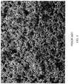
FIG. 1 is a scanning electron microphotograph (SEM, 2000x magnification) showing a porous membrane of prior art. -
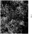
FIG. 2 andFIG. 3 are each an SEM (1000x magnification forFIG. 2 , 200x magnification forFIG. 3 ) of a porous membranes of the present invention comprising a first powder of nickel particles having an average size of 50 microns and a second powder of nickel particles having an average size of 2 microns. -
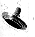
FIG. 4 is a schematic diagram of an exemplary embodiment of a device of the present invention. -
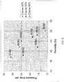
FIG 5 is a plot of a pressure drop (T adjusted) as a function of pressure across different porous membranes of the present invention. -
FIG. 6 is a plot of a pressure drop at 100 slpm (T adjusted) as a function of porosity measured for three different porous membranes of the present invention. -
FIG. 7 is a plot of the Log Reduction Values (LRV) as a function of porosity generated for different porous membranes of the present invention. -
FIG. 8 is a plot of deflection (movement due to pressure) of various membranes of the present invention measured as a function of applied force. -
FIG. 9 is a plot of flow rate through various porous membranes of the present invention measured as a function of differential pressure across the membrane (outlet kept at atmospheric pressure). - While various compositions and methods are described, it is to be understood that this invention is not limited to the particular molecules, compositions, methodologies or protocols described, as these may vary. It is also to be understood that the terminology used in the description is for the purpose of describing the particular versions or embodiments only, and is not intended to limit the scope of the present invention which will be limited only by the appended claims.
- As used herein and in the appended claims, the singular forms "a", "an", and "the" include plural reference unless the context clearly dictates otherwise. Unless defined otherwise, all technical and scientific terms used herein have the same meanings as commonly understood by one of ordinary skill in the art. Methods and materials similar or equivalent to those described herein can be used in the practice or testing of embodiments of the present invention. Nothing herein is to be construed as an admission that the invention is not entitled to antedate such disclosure by virtue of prior invention. "Optional" or "optionally" means that the subsequently described event or circumstance may or may not occur, and that the description includes instances where the event occurs and instances where it does not. All numeric values are herein can be modified by the term "about" or "substantially" whether or not explicitly indicated. The term "about" or "substantially" generally refers to a range of numbers that one of skill in the art would consider equivalent to the recited value (i.e., having the same function or result). In some embodiments the term "about" or "substantially" refers to ±10% of the stated value, in other embodiments the term "about" or "substantially" refers to ±2% of the stated value. While compositions and methods are described in terms of "comprising" various components or steps (interpreted as meaning "including, but not limited to"), the compositions and methods can also "consist essentially of" or "consist of" the various components and steps, such terminology should be interpreted as defining essentially closed-member groups.
- As used herein, the term "LRV" refers to "log reduction value," which is a measure of filtration efficiency under specified flow rate (or gas velocity), for a specified particle size and material thickness. An LRV value of 1 means that 90% of contaminants are retained by the filter, LRV of 2 means that 99% of contaminants are retained by the filter, LRV of 3 means that 99.9% of the contaminants are retained by the filter, etc. Any value of flow rate (gas velocity), particle size and material thickness can be selected to measure LRV of a porous membrane of the present invention. One of ordinary skill in the art would understand that specific values are a matter of convenience, experimental setup and/or intended use. For example, in one embodiment, LRV can be measured at velocity of about 3 splm/cm2, for a particles having an average size of 100 nm and the material thickness of about 0.4 cm (e.g., 0.44 cm). Alternatively, LRV can be measured at velocity of about 3 splm/cm2, for a particles having an average size of 10 nm and the material thickness of about 0.4 cm (e.g. 0.44 cm). Alternatively, LRV can be measured at velocity of about 3 splm/cm2, for a particles having an average size of 3 nm and the material thickness of about 0.4 cm (e.g. 0.44 cm).
- As used herein, a "strength" of a material of a filter (e.g. of a porous membrane) refers to the gas pressure at which the material will burst when the membrane is configured into disk that is welded at the circumference in the manner of a fixed flat plate. A typical pressure at which the strength is measured is 2068 kPa (300 psi).
- As used herein, the term "throughput" refers to a flow rate through a filter of a fixed cross-section at a fixed pressure.
- As used herein, the total internal surface of a unit of material is a value measured by the Brunauer-Emmett-Teller (BET) method. In summary, the BET method can be used to calculate surface areas of solids by physical adsorption of gas molecules. One of ordinary skill in the art or physics of surface would be able to employ the BET method for measuring the total internal surface of porous membranes of the present invention without undue experimentation.
- As used herein, the term "bubble point" refers to a value of pressure obtained by a bubble point pressure test. The bubble point pressure test measures the pressure necessary to force a gas (e.g., air) through the pores of a porous membrane previously wetted with a liquid. The liquid can be water, isopropyl alcohol (IPA), methanol, ethanol, or any other suitable liquid.
- As used herein, 1 pound per square inch equals 6,894.8 Pa. 100 kPa is equal to 1 bar.
- As used herein, "slpm" is a unit of flow, Standard Liters per Minute, as measured using the flow of nitrogen gas at 0 °C and 1.01 bar of pressure.
- A material has been developed which incorporates the fine pore structure with high strength and long lifecycle capability. This is accomplished by the blending of at lest one fine powder metal particles with at least one coarse metal powder metal particles, followed by sintering the blend together. This material, when incorporated into, for example an existing diffuser (membrane) design such as but not limited to the FV-50, manufactured by Entegris, Inc., is capable of handling pressures up to 75 pounds per square inch differential pressure (psi differential or "psid") and lifecycles of greater that 1,000,000 while offering up to 6 log particle reduction for 0.003 micron particles in a gas. In addition, the sintered membrane retains the flow profile of a sintered porous membrane made using fine nickel powders alone.
- Accordingly, in various embodiments, the invention comprises flat sheet membranes of a blend of at least one fine metal powder and at least coarse metal powder, each comprising metal particles, sintered together. The fine and coarse particles have different average sizes which can differ by a factor of about 5 to about 50, in some embodiments the fine and coarse particles have different average sizes which can differ by a factor of 50 or more.
- In one embodiment, the present invention is a porous membrane comprising a blend of a first powder of metal particles of the first average size and a second powder of metal particles of a second average size, the first powder and the second powder sintered together. In certain embodiments additional powders (a third, a fourth, etc.) can be used.
- Preferably, the first average size is five to fifty times greater than the second average size. In some embodiments, the porous membrane comprises from 40% to 60% by weight of the first powder, preferably, the porosity of the porous membrane is from 37 % by volume to 50 % by volume, more preferably, the porosity of the porous membrane is from 42 % by volume to 48 % by volume.
- In certain embodiments, the first average size is from about 40 microns to about 60 microns, and the second average size is not greater than about 2 microns, preferably, the first average size is about 50 microns, and the second average size is about 2 microns.
- The metal particles of the powders used in the porous membranes of the present invention can include particles of any sinterable metal suitable for the required application, as will be further described below. For examples, metals can be selected from iron, chromium, nickel, alloys containing nickel and steel. Alternatively, metal can be a refractory metal such as niobium or molybdenum, a precious metal such as gold or silver, or a superalloy such as Inconel® (a line of nickel-chromium alloys available from Special Metals Corporation, New York, U.S.A.,) or Hastalloy® (a line of nickel-based alloys available from Haynes International Inc., Indiana, USA). Preferably, the metal particles of the first powder and the metal particles of the second powder are each independently selected from nickel or stainless steel. In some embodiments, the metal particles of the first powder and the metal particles of the second powder are each selected from nickel.
- In exemplary embodiments, the porous membrane of the present invention exhibits a Log Reduction Value (LRV) from 4 to 6 for 0.1 micron particles, gas velocity of 3 slpm/cm2 and 0.4 centimeter thick membrane. Preferably, the porous membrane has a Log Reduction Value (LRV) is 6 or more for 0.1 micron particles, gas velocity of 3 slpm/cm2 and 0.4 centimeter thick membrane. Alternatively, the porous membrane of the present invention exhibits a Log Reduction Value (LRV) from 4 to 6 for 0.003 micron particles, gas velocity of 3 slpm/cm2 and 0.4 centimeter thick membrane. Preferably, the porous membrane has a Log Reduction Value (LRV) that is 6 or more for 0.003 micron particles, gas velocity of 3 slpm/cm2 and 0.4 centimeter thick membrane.
- In exemplary embodiments, the porous membrane of the present invention exhibits the water bubble point from 27.6 and 55.2 kPa (4 and 8 pounds per square inch).
- One embodiment of the invention is a porous diffuser (membrane) comprising a blend of about 40 wt. % to about 60 wt. % of a first set of metal particles having one average size and a second set of metal particles making up the balance of the diffuser (membrane) having a second average size smaller than the first set of metal particles. The fist set of metal particles are sintered together and the second set of metal particles sintered to each other and are sintered with the first set of metal particles. The diffuser (membrane) has a porosity in the range of about 37 % by volume to about 50 % by volume and pores of the diffuser (membrane) are distributed throughout the diffuser (membrane) body. The diffuser (membrane) has an LRV of 4 to an LRV of 6 for 0.1 micron particles and gas velocity of 3 slpm/cm2. The membrane can have a thickness from 0.2 cm to 0.5 cm. For example, the membrane can be about 0.4 centimeter thick diffuser. The membrane (diffuser) can have any diameter. For example, the membrane can have a diameter of 5.2 centimeters. The diffuser (membrane) has a burst pressure of at least 2068 kPa (300 psi), preferably greater than 2413 kPa (350 psi). Alternatively, LRV is measured under the same conditions except for particles having the average size of 0.003 micron.
- In some embodiments of the invention the first set of coarse metal particles has an average size of about 40 microns to about 60 microns, and said second set of metal particles has an average size of about 2 microns or less. In some versions the second set of metal particles has an average size of about 2 microns.
- The diffuser (membrane) in versions of the invention can have a porosity between about 42 vol % and about 48 vol % and an LRV of 6 or more for 0.1 micron particles in a gas. Alternatively, the diffuser (membrane) in versions of the invention can have a porosity between about 42 vol % and about 48 vol % and an LRV of 6 or more for 0.003 micron particles in a gas.
- The diffuser (membrane) remains integral after 1 million pressure cycles of 75 psid, where the pressure cycles have a duration of about 2 seconds.
- In one version of the invention, the first set of metal particles is nickel with a size of about 50 microns and the second set of metal particles is nickel with a size of 2 microns. A 0.44 centimeter thick diffuser (membrane) made from these particles as a flat sheet with a diameter of 5 cm centimeters can be characterized by an LRV of at least 6 in a gas for 0.1 micron particles, the diffuser (membrane) has a water bubble point of between 27.6 and 55.2 kPa (4 and 8 pounds per square inch), a nitrogen gas flow per unit area (at 18 pounds per square inch pressure inlet) of 5 slpm/cm2 and a burst pressure of greater than 2418 kPa (350 psi). Alternatively, LRV is measured under the same conditions except for particles having the average size of 0.003 micron.
- Sinterable powders of two different sizes, in some versions more than two sizes, can be blended together in versions of the invention. The sinterable powders in some versions of the invention can include corrosion resistant materials such as but not limited to nickel, those alloys containing nickel, alloys like stainless steel, and the like such as disclosed in
U.S. Pat. No. 5, 487, 771 . In some versions the metal particles are nickel. The size of the small metal particle powders in the blend are chosen to provide the surface area for gas particle reduction of about 9 LRV or higher for 0.003 micron test particles under standard particle reduction conditions (for example test conditions for an Entegris FV-50 filter) for a sintered filter made of only the small particles. The size of the large or coarse metal particles can be chosen so that when mixed with the smaller particles they can be pressed into a coherent green compact (i.e. an unsintered compacted powder) at pressures between 5516 kPa (800 psi) and 10342 kPa (1500 psi). The coarse particles can have a size that when mixed with the small particles in an amount of 40% by weight to 60% by weight provides a porous sintered membrane with porosity in the range of 40% by volume to 60% by volume and a pressure drop that is within about ±20% of the pressure drop for a filter made with the small particles alone. In some versions of the invention the coarse particles can have a size that when mixed with the small particles in an amount of 40% by weight to 60% by weight provides a porous sintered membrane with porosity in the range of 40% by volume to 60% by volume and a pressure drop that is within about ±10% of the pressure drop for a filter made with the small particles alone. - Small or fine particles that can be sintered have a size of 10 micron or less. Coarse or large particles that can be sintered can have a size of 10 microns or more.
- The porous sintered membrane compositions in versions of the invention have an LRV which is not dependent, or weakly dependent, on overall porosity and percent blend of powders. Rather, in order to maximize LRV, the thickness of the material is increased.
- The appearance of the porous membranes of the present invention can be further understood with reference to
FIG. 1 ,FIG. 2 andFIG. 3 .FIG. 1 is a SEM microphotograph showing a porous membrane of prior art, comprising a powder of monodispersed (single-size) metal particles sintered together.FIG. 2 andFIG. 3 are each an SEM microphotograph (at different magnification) of a porous membranes of the present invention comprising a first powder of nickel particles having an average size of 50 microns and a second powder of nickel particles having an average size of 2 microns. - Referring to
FIG. 4 , in one embodiment, the present invention is agas diffuser device 100, comprisinghousing 102, havinginlet 104 andoutlet 106. A porous membrane of thepresent invention 108 is disposed withinhousing 102 in fluid communication withinlet 104 andoutlet 106. Any of the porous membranes described herein can be employed indevice 100. - In exemplary embodiments,
device 100 comprisesporous membrane 108 manufactured as a flat sheet having a thickness of 2.54 mm (0.1 inch) or more. In one embodiment,device 100 comprisesporous membrane 108 manufactured as a flat sheet having a thickness (h) of from about 0.2 cm to about 0.5 cm. For example,membrane 108 can have a thickness of about 0.40 cm or 0.44 cm.Membrane 108 can have any diameter. For example,membrane 108 can have and a diameter (D) of 5.2 centimeters. In further embodiments, the Log Reduction Value of the porous membrane is at least 6 in a gas for 0.1 micron particles. Alternatively, LRV is measured under the same conditions except for particles having the average size of 0.003 micron. In exemplary embodiments, the porous membrane of thegas diffuser device 100 exhibits a burst pressure of at least 2068 kPa (300 psi), preferably, greater than 2413 kPa (350 psi). - In one embodiment, the present invention is a method of purifying a gas stream. The method comprises directing a gas stream through a porous membrane of the present invention. Any of the porous membranes described herein can be employed. In one embodiment,
device 100 shown inFIG. 4 can be employed to purify a gas stream. - Porous membranes of the present invention were prepared using methods described herein. LRV values of the porous membranes of the present invention are independent of the overall porosity and composition of the starting particle powders. No measurable relationship between LRV and the starting powder composition and membrane porosity was found. The LRV of the porous membranes of the present invention increases with growing thickness of the final sintered porous membrane. The porosity and the composition of the starting powder can be modified to tailor the sintered porous membrane for a desired pressure drop.
- In the experiments described below, the porous membranes of the present invention were prepared using, as a starting material, a blend of Vale Inco Type 255 nickel powder (2 micron filamentary nickel powder available from Novamet Specialty Products, New Jersey, USA), and a "coarse" 50
micron Ametek® 200 nickel powder is a nickel powder available from Ametek® Specialty Metal Product Division, Pennsylvania, USA. It is noted that Vale Inco Type 255 nickel powder is used in manufacturing Entegris WaferGuard® NF line of porous membranes. NF membrane is manufactured by sintering Vale Inco Type 255 powder. - A number of membranes containing fine powder and coarse powder were made with proportions as show in the Table 1 below.
Table 1 Disk # % Desired Porosity % Coarse Powder 1 40.00 40.00 2 50.00 50.00 3 60.00 60.00 4 40.00 60.00 5 50.00 40.00 6 60.00 50.00 7 40.00 50.00 8 50.00 60.00 9 60.00 40.00 - A 73.7 mm (2.9 inch) mold was used to make the green form disks using the force (in pounds) and percentage of coarse powder given in the Table 2 below. The thickness of the green form in centimeters was estimated. The mass of coarse Ni powder in grams and the mass of the fine
Vale Inco Type 255, 2 micron powder in grams are also given:Table 2 Disk # % Desired Porosity % Coarse Powder Mass Required Mass Coarse-g Mass 255-g Estimated Mold t-cm Press (pounds) 1 40.00 40.00 52.4 21.0 31.4 1.000 15,000 2 50.00 50.00 43.0 21.5 21.5 0.723 10,000 3 60.00 60.00 33.4 20.0 13.4 0.488 4,000 4 40.00 60.00 52.4 31.4 21.0 0.767 14,000 5 50.00 40.00 43.0 17.0 26.0 0.819 10,000 6 60.00 50.00 33.4 16.7 16.7 0.563 5,000 7 40.00 50.00 52.4 26.2 26.3 0.884 15,000 8 50.00 60.00 43.0 26.0 17.0 0.628 12,000 9 60.00 40.00 33.4 13.4 20.0 0.637 5,000 - Sintering at 1050 °C will result in a greater sinter bonding in the Vale Inco Type 255 powder than sintering at a lower temperature. Sintering at temperatures above 1050 °C can lead to loss of surface area with a subsequent drop in LRV values for the porous membranes of the present invention.
- Porosities ranged from about 37 to 51%. Previous experimentation had shown that sintering at temperatures lower than 1050 °C resulted in significant loss of porous sintered membrane strength.
- The final cut disks (47 mm) had the characteristics listed in Table 3. (In Table 3, mass is in grams (g), "Od" is outside diameter of disk in centimeters (cm), "t" is the thickness of the disk in centimeters (cm), ρ is the density of the disk in grams/cubic centimeter (g/cc), Po is the porosity in percent, and ID refers to the overall porosity and percent of coarse powder. For example "37/40" refers to 37% overall porosity and 40% by weight of 50 micron powder.)
Table 3 Disk # Mass-g Od-cm t-cm v-cc p-g/cc % Po ID 1 27.90 4.740 0.285 5.028 5.548744 37.51 37/40 2 18.26 4.740 0.220 3.881 4.704500 47.02 47/50 3 19.35 4.740 0.250 4.411 4.387088 50.60 50/60 4 28.10 4.730 0.310 5.446 5.159581 41.90 42/60 5 19.90 4.740 0.220 3.881 5.127029 42.26 42/40 6 19.10 4.740 0.235 4.146 4.606816 48.12 48/50 7 27.47 4.740 0.285 5.028 5.463226 38.48 38/50 8 21.70 4.740 0.240 4.234 5.124882 42.29 42/60 9 17.20 4.735 0.200 3.521 4.884842 44.99 45/40 - Since thickness varied and post-sintering pressing would skew the results, all measured values were adjusted to a standard thickness of 2.54 mm. One of ordinary kill in the art would appreciate that, although the thickness of the membranes in this example varied from about 0.2 cm to about 0.31 cm, a different thickness can be chosen based on convenience, intended application and desired result. For example, the thickness of a membrane can be chosen from a range of about 0.2 cm to about 0.5 cm. In one example, the thickness can take any of the values listed in Table 3. In another example, the thickness can be 0.4 cm. In yet another example, the thickness can be 0.44 cm.
- Pressure drops generated by the porous membranes listed in Table 3 (identified by "ID") were measured and the results are shown in
FIG. 5 . InFIG. 5 , the Y-axis is the flow (q)/area (a) (units are liters per minute/centimeters squared), while the X-axis is pressure (in pounds per square inch). The pressure drop was adjusted to a standard thickness of 2.54 millimeters. "NF Membrane" refers to a flat sheet porous membrane manufactured by Entegris, Inc. using a single-size Ni powder Vale Inco Type 255. - The data presented in
FIG. 5 shows that the porous membrane with a pressure drop closest to the NF membrane was a material with 60% 50 micron powder, 40% Vale Inco Type 255 and an overall porosity of 42%. These results show that it is possible to reduce pressure drop over the existing membrane based on the composition of the starting blended powder. This conclusion was further confirmed by the measurement of the pressure drop as a function of porosity for three different compositions of the starting powder blends. The results are presented inFIG. 6 . - Particle reduction and LRV of the membranes of the present invention were measure based on Semi F3 8-0699 "Test Method for efficiency Qualification of Point of Use Gas Filters", incorporated herein by reference in its entirety. Table 4, below, lists the values of the LRV for selected membranes listed by the "IDs."
Table 4 Disk # LRV1 ID 1 3.24 37/40 2 4.31 47/50 3 3.39 50/60 4 3.38 42/60 5 4.31 42/40 6 3.72 48/50 7 4.81 38/50 8 3.22 42/60 9 4.49 45/40 1 Measured for particles of 0.1 microns on a 2.54 mm thick disk having the diameter of 4.74 cm, at 40 slpm/cm2. - It was previously accepted by those of ordinary skill in the art that the sample with the least porosity and lowest percentage of coarse powder would have the highest LRV. Unexpectedly, it was found that the LRV of the membranes of the present invention was not measurably impacted by porosity and percent of the coarse powder in the starting blend. The results are illustrated by the plot shown in
FIG. 7 . - The results shown in
FIG. 7 suggest that an increase of thickness of a membrane optimized for flow performance (by, e.g., adjusting porosity and/or composition of the starting blended powder) will result in higher LRV. For example, for a porous membrane of the present invention manufactured from a starting blend of 60% 50 micron particles and being 50 % porous (ID 50/60 in Table 3), a value of 6 LRV may be obtainable with a thickness of 0.4 cm while having a pressure drop of 124.1kPa (18 psi) for gas velocity of 5 slpm/cm2 for a 47 mm disk diameter. This flow is a comparable with that through an existing NF membrane manufactured by Entegris, Inc. - It is noted that the porous materials of the present invention exhibit an LRV value close to 6. Such values are considered high enough to be provide high efficiency filtration (99.9999% efficient). For a material having high LRV, the thickness of the material could be increased, this also increase strength. For example, 0.180 inch thick membrane prepared from a single-size of 2 micron nickel powder Vale Inco Type 255 exhibits mass of per unit area was 0.8 g/cm2.
- Strength of the porous membranes of the present invention was measured as the gas pressure at which the material will burst when the membrane is configured into disk that is welded at the circumference in the manner of a fixed flat plate. FV-50 product manufactured by Entegris, Inc. (a porous membrane manufactured from a single-
size 50 micron Ni particles) generally ruptures between 517.1-689.5 kPa (75-100 psi) for a disk with a diameter of 52.1 mm (2.05 inch) and a thickness of 2.54 mm (0.100 inch). The 42% porous disk with 60% 50 micron powder of the same dimensions could not be ruptured with pressures up to 2413 kPa (350 psi). - All measurements described in Examples 5 through 7 (and illustrated by the plots in
FIG. 8 andFIG. 9 ) were performed using a device shown inFIG. 4 . The porous membrane of this device was manufactured from the material of ID 42/60 (as described in Table 3), in the shape of a disk having the thickness of 0.44 cm and the diameter of 5.2 cm. - Two samples of the porous membrane of the present invention (referred to as FV-
50DXL # 1 and FV-50 DXL #2) were compared to two control samples (refered to as FV-50D # 1 and FV-50D #2). "FV-50D" is a product manufactured by Entegris, Inc. (a porous membrane manufactured from 50 micron Ni particles), while FV-50 DXL is a device manufactured from the material ID 42/60, as described above. - Deflection (movement due to pressure) of the membrane material was measured as a function of applied force. The results are shown in
FIG. 8 . - The results of the tests show that for disks of the same diameter, the porous membranes of the present invention have a deflection of less than 0.0508 mm (0.002 inches), even less than 0.0254 mm (0.001 inches), at an inlet pressure to the disk of 344.7 kPa (50 psi) and with outlet pressure at normal atmospheric pressure.
- Bubble point testing indicates a porous membrane of the present invention has a larger pore size than a porous membrane prepared by sintering a single-size Vale Inco Type 255 powder. The porous membrane manufactured by sintering a single-size Vale Inco Type 255 powder has a bubble point of approximately 10 psi in water, while the tested porous membrane of the present invention has a bubble point at approximately 41.4 kPa (6 psi).
- A sample of the porous membrane of the present invention (referred to as FV-50DXL) was compared to a control sample (referred to as FV-50D). "FV-50D" is a product manufactured by Entegris, Inc. (a porous membrane manufactured from 50 micron Ni particles), while FV-50 DXL is a device manufactured from the material ID 42/60, as described above.
- Flow rate through the porous membranes of the present invention was measured as a function of differential pressure across the membrane. The results were compared with the porous membranes manufactured from single-size metal powders having various average particle sizes. The experiment was performed as follows. Gas (air) was introduced into the inlet of the device at a know pressure. The outlet pressure was kept constant at atmospheric pressure. The volumetric mass flow rate of this gas was measured with a mass flow meter. This was done at several different inlet pressures. A plot was prepared of the of the volumetric mass flow verses the inlet pressure.
- The results are presented in
FIG. 9 . As can be seen, flow characteristics of the porous membranes of the present invention show close correlation with the membranes manufactured form single-size powders. - Provided below in Table 5 is a summary of the properties of one embodiment of the porous membrane of the present invention manufactured by sintering a Vale Inco Type 255 nickel powder (2 micron) and a "coarse" nickel powder having an average particle size of 50 microns. Also provided for comparison are the properties of a porous membrane manufactured by sintered a single-size Vale Inco Type 255 nickel powder.
Table 5 Control Membrane of the invention Mass of Vale Inco Type 255 2 µm, g 14.2 14.4 Mass of AMETEK 200 50 µm,g 0 21.6 Total mass, g 14.2 36 Compaction pressure, psi <1000 1000 Thickness, cm 0.254 0.4445 Diameter, cm 5.0 5.0 Porosity, % 65 42 Burst, psi 110 >350 Flow/area @ 18 psi-slpm/ cm 25 5 LRV @ 3 splm/ cm 29 6 Bubble point- water 10 6 - While this invention has been particularly shown and described with references to example embodiments thereof, it will be understood by those skilled in the art that various changes in form and details may be made therein without departing from the scope of the invention encompassed by the appended claims.
Claims (15)
- A porous membrane, comprising a blend of a first powder of metal particles of a first average size and a second powder of metal particles of a second average size, the first powder and the second powder being sintered together,
wherein the first average size is five to fifty times greater than the second average size, and wherein the porous membrane comprises from 40% to 60% by weight of the first powder, characterised in that the first average size is 50 microns, and the second average size is 2 microns. - The porous membrane according to claim 1, wherein the water bubble point of the porous membrane is from 27.5 to 55.2 kPa (4 to 8 psi), measured under test conditions where a control porous membrane made by sintering a mass of 14.2g of Vale Inco Type 255 nickel powder at a compaction pressure of greater than 6894.8 kPa (1000 psi) to a thickness of 0.254cm and a diameter of 5.0cm has a water bubble point of 68.9 kPa (10 psi).
- The porous membrane according to claim 1 or claim 2, wherein the porous membrane has a Log Reduction Value (LRV) equal to or greater than 4 for 0.1 micron particles in a gas having velocity of 3 standard litres per minute (slpm)/cm2, wherein slpm is measured on a 0.4 centimeter thick membrane using flow of nitrogen gas at 0°C and 1.01 kPa (1.01 bar) pressure, wherein the LRV is measured using the test method Semi F38-0699.
- The porous membrane according to claim 1, whereina) a porosity of the porous membrane is from 37 % by volume to 50 % by volume, orb) a porosity of the porous membrane is from 42 % by volume to 48 % by volume, orc) the metal particles of the first powder and the metal particles of the second powder are each independently selected from nickel or stainless steel, ord) the metal particles of the first powder and the metal particles of the second powder are each selected from nickel.
- A gas diffuser device comprising:a housing having an inlet and an outlet; anda porous membrane according to any preceding claim disposed within the housing in fluid communication with the inlet and the outlet.
- The device according to claim 5, wherein the porous membrane is a flat sheet having a thickness of 0.25cm (0.1 inch) or more.
- The device according to claim 5, wherein the porous membrane is a flat sheet having a thickness from 0.2 cm to 0.5 cm, and further wherein the LRV of the porous membrane is at least 6 in a gas for 0.1 micron particles and velocity of 3 slpm/cm2.
- The device according to claim 7, wherein the porous membrane has a burst pressure ofa) at least 2068 kPa (300 pounds per square inch), orb) greater than 2413 kPa (350 pounds per square inch).
- The device according to claim 5,
wherein the porous membrane is a flat sheet having a thickness from 0.2 cm to 0.5 cm, having an LRV of at least 6 in a gas for 0.1 micron particles and velocity of 3 slpm/cm2, and a burst pressure of at least 2068 kPa (300 pounds per square inch). - A method of purifying a gas stream, comprising:directing a gas stream through a porous membrane, said porous membrane comprising a blend of a first powder of metal particles of a first average size and a second powder of metal particles of a second average size, the first powder and the second powder being sintered together,wherein the first average size is five to fifty times greater than the second average size, andwherein the porous membrane comprises from 40% to 60% by weight of the first powder,wherein the first average size is 50 microns, and the second average size is 2 microns,thereby purifying the gas stream.
- The method according to claim 10, wherein the water bubble point of the porous membrane is from 27.5 to 55.2 kPa (4 to 8 psi), measured under test conditions where a control porous membrane made by sintering a mass of 14.2g of Vale Inco Type 255 nickel powder at a compaction pressure of greater than 6894.8kPa (1000 psi) to a thickness of 0.254cm and a diameter of 5.0cm has a water bubble point of 68.9 kPa (10 psi).
- The method according to claim 10 or claim 11, wherein the porous membrane has a Log Reduction Value (LRV) equal to or greater than 4 for 0.1 micron particles in a gas having velocity of 3 standard litres per minute (slpm)/cm2, wherein slpm is measured on a 0.4 centimeter thick membrane using flow of nitrogen gas at 0°C and 1.01 kPa (1.01 bar) pressure, wherein the LRV is measured using the test method Semi F38-0699.
- The method according to any one of claims 10 to 12, whereina) a porosity of the porous membrane is from 37 % by volume to 50 % by volume, orb) a porosity of the porous membrane is from 42 % by volume to 48 % by volume, orc) the metal particles of the first powder and the metal particles of the second powder are each independently selected from nickel or stainless steel, ord) the metal particles of the first powder and the metal particles of the second powder are each selected from nickel, ore) the porous membrane is a flat sheet having a thickness of 0.25cm (0.1 inch) or more.
- The method according to claim 10, wherein the porous membrane is a flat sheet having a thickness from 0.2 cm to 0.5 cm, and further wherein the LRV of the porous membrane is at least 6 in a gas for 0.1 micron particles and velocity of 3 slpm/cm2
- The method according to claim 14, wherein the porous membrane has a burst pressure of:a) at least 2068 kPa (300 pounds per square inch), orb) greater than 2413 kPa (350 pounds per square inch).
Applications Claiming Priority (2)
| Application Number | Priority Date | Filing Date | Title |
|---|---|---|---|
| US21831009P | 2009-06-18 | 2009-06-18 | |
| PCT/US2010/038763 WO2010148051A2 (en) | 2009-06-18 | 2010-06-16 | Sintered porous material comprising particles of different average sizes |
Publications (3)
| Publication Number | Publication Date |
|---|---|
| EP2442898A2 EP2442898A2 (en) | 2012-04-25 |
| EP2442898A4 EP2442898A4 (en) | 2013-10-23 |
| EP2442898B1 true EP2442898B1 (en) | 2019-01-02 |
Family
ID=43357023
Family Applications (1)
| Application Number | Title | Priority Date | Filing Date |
|---|---|---|---|
| EP10790093.8A Active EP2442898B1 (en) | 2009-06-18 | 2010-06-16 | Sintered porous material comprising particles of different average sizes |
Country Status (8)
| Country | Link |
|---|---|
| US (1) | US8932381B2 (en) |
| EP (1) | EP2442898B1 (en) |
| JP (1) | JP5639164B2 (en) |
| KR (1) | KR101841778B1 (en) |
| CN (1) | CN102458624B (en) |
| SG (1) | SG176877A1 (en) |
| TW (1) | TWI511816B (en) |
| WO (1) | WO2010148051A2 (en) |
Families Citing this family (11)
| Publication number | Priority date | Publication date | Assignee | Title |
|---|---|---|---|---|
| US9678091B2 (en) * | 2012-10-02 | 2017-06-13 | Stamford Scientific International, Inc. | In situ monitoring for wastewater treatment systems and the like |
| WO2015161245A1 (en) | 2014-04-18 | 2015-10-22 | Entegris, Inc. | High purity gas purifier |
| CN104625071B (en) * | 2015-01-28 | 2016-09-28 | 东莞劲胜精密组件股份有限公司 | A kind of preparation method of powder injection-molded surface pore material |
| CN111519166A (en) | 2015-02-13 | 2020-08-11 | 恩特格里斯公司 | Composite Atomic Layer Deposition (ALD) coating on substrate portion and method of forming patterned ALD coating on substrate portion |
| AT14884U1 (en) * | 2015-07-10 | 2016-08-15 | Plansee Se | metal filter |
| CN107695346B (en) * | 2017-11-23 | 2023-06-06 | 北京科技大学 | Device and method for preparing and characterizing aluminum alloy material in high flux by powder metallurgy method |
| US10837603B2 (en) * | 2018-03-06 | 2020-11-17 | Entegris, Inc. | Gas supply vessel |
| US10974183B2 (en) | 2018-03-14 | 2021-04-13 | Coorstek Kk | Break filter using a silicon carbide porous body and manufacturing method of the break filter |
| EP3775743A4 (en) | 2018-11-26 | 2021-12-01 | Hewlett-Packard Development Company, L.P. | Sintering furnace |
| WO2020123120A1 (en) * | 2018-12-14 | 2020-06-18 | Entegris, Inc. | Composite nanoporous metal membrane |
| WO2023212321A1 (en) * | 2022-04-29 | 2023-11-02 | Entegris, Inc. | Sintered porous body with multiple layers |
Family Cites Families (23)
| Publication number | Priority date | Publication date | Assignee | Title |
|---|---|---|---|---|
| US4186100A (en) * | 1976-12-13 | 1980-01-29 | Mott Lambert H | Inertial filter of the porous metal type |
| JPS57169002A (en) | 1981-04-06 | 1982-10-18 | Nippon Seisen Kk | Sintered body |
| GB8914023D0 (en) * | 1989-06-19 | 1989-08-09 | Alcan Int Ltd | Porous ceramic membrane method |
| US5114447A (en) * | 1991-03-12 | 1992-05-19 | Mott Metallurgical Corporation | Ultra-high efficiency porous metal filter |
| JPH05287328A (en) * | 1992-04-14 | 1993-11-02 | Hitachi Metals Ltd | Production of metallic separation membrane |
| US5908662A (en) | 1992-04-27 | 1999-06-01 | Texas Instruments Incorporated | Method and apparatus for reducing particle contamination |
| RU2038217C1 (en) * | 1992-12-07 | 1995-06-27 | Лев Хатевич Певзнер | Laminated porous material |
| DE69401031T2 (en) * | 1993-06-04 | 1997-04-30 | Millipore Corp | Metal filter element with high efficiency and process for its production |
| US5364586A (en) * | 1993-08-17 | 1994-11-15 | Ultram International L.L.C. | Process for the production of porous membranes |
| US5814272A (en) * | 1996-02-21 | 1998-09-29 | Millipore Corporation | Method for forming dendritic metal particles |
| CA2190238A1 (en) * | 1996-07-15 | 1998-01-15 | Ryutaro Motoki | Sintered metal filters |
| CN100439013C (en) * | 2001-02-16 | 2008-12-03 | 株式会社大阪钛技术 | Titanium powder sintered compact |
| JP4144185B2 (en) | 2001-03-12 | 2008-09-03 | 三菱マテリアル株式会社 | Method for producing porous metal body having excellent ductility |
| AU2003302247A1 (en) * | 2002-12-12 | 2004-07-09 | Mykrolis Corporation | Porous sintered composite materials |
| DE10319300B4 (en) * | 2003-04-29 | 2006-03-30 | Wacker Chemie Ag | Process for producing a shaped body of silica glass |
| DE10331049B4 (en) * | 2003-07-09 | 2010-04-08 | Saint-Gobain Industriekeramik Rödental GmbH | A process for producing a porous ceramic body, then produced porous ceramic body and its use |
| DE102005038074A1 (en) * | 2005-08-10 | 2007-02-15 | BEGO Bremer Goldschlägerei Wilh. Herbst GmbH & Co. KG | Preparation of metallic structural element, providing electrophoretically refinable metal sludge, electrophoretically separating a layer of particle from sludge and sintering/unsintering |
| EP1941127A1 (en) * | 2005-10-24 | 2008-07-09 | Shell Oil Company | Systems and methods for producing hydrocarbons from tar sands with heat created drainage paths |
| US7524361B2 (en) * | 2006-01-12 | 2009-04-28 | Korea Institute Of Energy Research | Porous hydrogen separation membrane and method for preparing the same |
| JP4902455B2 (en) * | 2006-08-01 | 2012-03-21 | 東レ東燃機能膜合同会社 | Polyolefin multilayer microporous membrane, method for producing the same, battery separator and battery |
| US7744675B2 (en) * | 2006-11-08 | 2010-06-29 | Shell Oil Company | Gas separation membrane comprising a substrate with a layer of coated inorganic oxide particles and an overlayer of a gas-selective material, and its manufacture and use |
| US8048199B2 (en) * | 2007-02-20 | 2011-11-01 | Shell Oil Company | Method of making a leak stable gas separation membrane system |
| US8007573B2 (en) * | 2007-09-28 | 2011-08-30 | General Electric Company | Filter and associated method |
-
2010
- 2010-06-16 WO PCT/US2010/038763 patent/WO2010148051A2/en active Application Filing
- 2010-06-16 CN CN201080026549.8A patent/CN102458624B/en active Active
- 2010-06-16 SG SG2011093127A patent/SG176877A1/en unknown
- 2010-06-16 KR KR1020127001294A patent/KR101841778B1/en active IP Right Grant
- 2010-06-16 US US13/375,844 patent/US8932381B2/en active Active
- 2010-06-16 EP EP10790093.8A patent/EP2442898B1/en active Active
- 2010-06-16 JP JP2012516224A patent/JP5639164B2/en active Active
- 2010-06-18 TW TW099119842A patent/TWI511816B/en active
Non-Patent Citations (1)
| Title |
|---|
| None * |
Also Published As
| Publication number | Publication date |
|---|---|
| US8932381B2 (en) | 2015-01-13 |
| JP5639164B2 (en) | 2014-12-10 |
| WO2010148051A3 (en) | 2011-04-21 |
| SG176877A1 (en) | 2012-01-30 |
| US20120079940A1 (en) | 2012-04-05 |
| EP2442898A4 (en) | 2013-10-23 |
| WO2010148051A2 (en) | 2010-12-23 |
| JP2012530592A (en) | 2012-12-06 |
| KR101841778B1 (en) | 2018-05-04 |
| KR20120027539A (en) | 2012-03-21 |
| CN102458624A (en) | 2012-05-16 |
| EP2442898A2 (en) | 2012-04-25 |
| TWI511816B (en) | 2015-12-11 |
| CN102458624B (en) | 2015-06-03 |
| TW201111071A (en) | 2011-04-01 |
Similar Documents
| Publication | Publication Date | Title |
|---|---|---|
| EP2442898B1 (en) | Sintered porous material comprising particles of different average sizes | |
| JP5129926B2 (en) | Porous sintered composite material | |
| US5487771A (en) | High-efficiency metal membrane element, filter, and process for making | |
| EP1093394B1 (en) | Composite porous media | |
| EP3397412A1 (en) | Porous devices made by laser additive manufacturing | |
| JPH04317710A (en) | Superhigh efficiency porous metal filter | |
| JP2014510836A (en) | Sintered powder and metal fiber porous metal membrane | |
| US20160220933A1 (en) | Sintered fe-al based porous alloy material with high-temperature oxidization resistance and filtering elements | |
| US20240001307A1 (en) | Composite nanoporous metal membrane | |
| JP2004521732A (en) | A filter having a structure arranged in a grade order and a method for manufacturing the same. | |
| US20230347300A1 (en) | Sintered porous body with multiple layers | |
| JPH05195110A (en) | Production of porous metal body | |
| JPH0889731A (en) | Filter made of metal powder and its production | |
| Tada et al. | Development of Titanium Filter made of Sintered Spherical Powder. |
Legal Events
| Date | Code | Title | Description |
|---|---|---|---|
| PUAI | Public reference made under article 153(3) epc to a published international application that has entered the european phase |
Free format text: ORIGINAL CODE: 0009012 |
|
| 17P | Request for examination filed |
Effective date: 20111128 |
|
| AK | Designated contracting states |
Kind code of ref document: A2 Designated state(s): AL AT BE BG CH CY CZ DE DK EE ES FI FR GB GR HR HU IE IS IT LI LT LU LV MC MK MT NL NO PL PT RO SE SI SK SM TR |
|
| DAX | Request for extension of the european patent (deleted) | ||
| A4 | Supplementary search report drawn up and despatched |
Effective date: 20130920 |
|
| RIC1 | Information provided on ipc code assigned before grant |
Ipc: B01D 69/00 20060101ALI20130916BHEP Ipc: B01D 71/00 20060101AFI20130916BHEP Ipc: B01D 67/00 20060101ALI20130916BHEP |
|
| STAA | Information on the status of an ep patent application or granted ep patent |
Free format text: STATUS: EXAMINATION IS IN PROGRESS |
|
| 17Q | First examination report despatched |
Effective date: 20170420 |
|
| GRAP | Despatch of communication of intention to grant a patent |
Free format text: ORIGINAL CODE: EPIDOSNIGR1 |
|
| STAA | Information on the status of an ep patent application or granted ep patent |
Free format text: STATUS: GRANT OF PATENT IS INTENDED |
|
| INTG | Intention to grant announced |
Effective date: 20180706 |
|
| GRAS | Grant fee paid |
Free format text: ORIGINAL CODE: EPIDOSNIGR3 |
|
| GRAJ | Information related to disapproval of communication of intention to grant by the applicant or resumption of examination proceedings by the epo deleted |
Free format text: ORIGINAL CODE: EPIDOSDIGR1 |
|
| GRAL | Information related to payment of fee for publishing/printing deleted |
Free format text: ORIGINAL CODE: EPIDOSDIGR3 |
|
| STAA | Information on the status of an ep patent application or granted ep patent |
Free format text: STATUS: EXAMINATION IS IN PROGRESS |
|
| GRAR | Information related to intention to grant a patent recorded |
Free format text: ORIGINAL CODE: EPIDOSNIGR71 |
|
| STAA | Information on the status of an ep patent application or granted ep patent |
Free format text: STATUS: GRANT OF PATENT IS INTENDED |
|
| GRAA | (expected) grant |
Free format text: ORIGINAL CODE: 0009210 |
|
| STAA | Information on the status of an ep patent application or granted ep patent |
Free format text: STATUS: THE PATENT HAS BEEN GRANTED |
|
| INTC | Intention to grant announced (deleted) | ||
| AK | Designated contracting states |
Kind code of ref document: B1 Designated state(s): AL AT BE BG CH CY CZ DE DK EE ES FI FR GB GR HR HU IE IS IT LI LT LU LV MC MK MT NL NO PL PT RO SE SI SK SM TR |
|
| INTG | Intention to grant announced |
Effective date: 20181126 |
|
| REG | Reference to a national code |
Ref country code: GB Ref legal event code: FG4D |
|
| REG | Reference to a national code |
Ref country code: CH Ref legal event code: EP Ref country code: AT Ref legal event code: REF Ref document number: 1083668 Country of ref document: AT Kind code of ref document: T Effective date: 20190115 |
|
| REG | Reference to a national code |
Ref country code: DE Ref legal event code: R096 Ref document number: 602010056271 Country of ref document: DE |
|
| REG | Reference to a national code |
Ref country code: IE Ref legal event code: FG4D |
|
| REG | Reference to a national code |
Ref country code: NL Ref legal event code: MP Effective date: 20190102 |
|
| REG | Reference to a national code |
Ref country code: LT Ref legal event code: MG4D |
|
| REG | Reference to a national code |
Ref country code: AT Ref legal event code: MK05 Ref document number: 1083668 Country of ref document: AT Kind code of ref document: T Effective date: 20190102 |
|
| PG25 | Lapsed in a contracting state [announced via postgrant information from national office to epo] |
Ref country code: NL Free format text: LAPSE BECAUSE OF FAILURE TO SUBMIT A TRANSLATION OF THE DESCRIPTION OR TO PAY THE FEE WITHIN THE PRESCRIBED TIME-LIMIT Effective date: 20190102 |
|
| PG25 | Lapsed in a contracting state [announced via postgrant information from national office to epo] |
Ref country code: SE Free format text: LAPSE BECAUSE OF FAILURE TO SUBMIT A TRANSLATION OF THE DESCRIPTION OR TO PAY THE FEE WITHIN THE PRESCRIBED TIME-LIMIT Effective date: 20190102 Ref country code: ES Free format text: LAPSE BECAUSE OF FAILURE TO SUBMIT A TRANSLATION OF THE DESCRIPTION OR TO PAY THE FEE WITHIN THE PRESCRIBED TIME-LIMIT Effective date: 20190102 Ref country code: LT Free format text: LAPSE BECAUSE OF FAILURE TO SUBMIT A TRANSLATION OF THE DESCRIPTION OR TO PAY THE FEE WITHIN THE PRESCRIBED TIME-LIMIT Effective date: 20190102 Ref country code: FI Free format text: LAPSE BECAUSE OF FAILURE TO SUBMIT A TRANSLATION OF THE DESCRIPTION OR TO PAY THE FEE WITHIN THE PRESCRIBED TIME-LIMIT Effective date: 20190102 Ref country code: PL Free format text: LAPSE BECAUSE OF FAILURE TO SUBMIT A TRANSLATION OF THE DESCRIPTION OR TO PAY THE FEE WITHIN THE PRESCRIBED TIME-LIMIT Effective date: 20190102 Ref country code: PT Free format text: LAPSE BECAUSE OF FAILURE TO SUBMIT A TRANSLATION OF THE DESCRIPTION OR TO PAY THE FEE WITHIN THE PRESCRIBED TIME-LIMIT Effective date: 20190502 Ref country code: NO Free format text: LAPSE BECAUSE OF FAILURE TO SUBMIT A TRANSLATION OF THE DESCRIPTION OR TO PAY THE FEE WITHIN THE PRESCRIBED TIME-LIMIT Effective date: 20190402 |
|
| PG25 | Lapsed in a contracting state [announced via postgrant information from national office to epo] |
Ref country code: BG Free format text: LAPSE BECAUSE OF FAILURE TO SUBMIT A TRANSLATION OF THE DESCRIPTION OR TO PAY THE FEE WITHIN THE PRESCRIBED TIME-LIMIT Effective date: 20190402 Ref country code: GR Free format text: LAPSE BECAUSE OF FAILURE TO SUBMIT A TRANSLATION OF THE DESCRIPTION OR TO PAY THE FEE WITHIN THE PRESCRIBED TIME-LIMIT Effective date: 20190403 Ref country code: LV Free format text: LAPSE BECAUSE OF FAILURE TO SUBMIT A TRANSLATION OF THE DESCRIPTION OR TO PAY THE FEE WITHIN THE PRESCRIBED TIME-LIMIT Effective date: 20190102 Ref country code: IS Free format text: LAPSE BECAUSE OF FAILURE TO SUBMIT A TRANSLATION OF THE DESCRIPTION OR TO PAY THE FEE WITHIN THE PRESCRIBED TIME-LIMIT Effective date: 20190502 Ref country code: HR Free format text: LAPSE BECAUSE OF FAILURE TO SUBMIT A TRANSLATION OF THE DESCRIPTION OR TO PAY THE FEE WITHIN THE PRESCRIBED TIME-LIMIT Effective date: 20190102 |
|
| REG | Reference to a national code |
Ref country code: DE Ref legal event code: R097 Ref document number: 602010056271 Country of ref document: DE |
|
| PG25 | Lapsed in a contracting state [announced via postgrant information from national office to epo] |
Ref country code: CZ Free format text: LAPSE BECAUSE OF FAILURE TO SUBMIT A TRANSLATION OF THE DESCRIPTION OR TO PAY THE FEE WITHIN THE PRESCRIBED TIME-LIMIT Effective date: 20190102 Ref country code: RO Free format text: LAPSE BECAUSE OF FAILURE TO SUBMIT A TRANSLATION OF THE DESCRIPTION OR TO PAY THE FEE WITHIN THE PRESCRIBED TIME-LIMIT Effective date: 20190102 Ref country code: AL Free format text: LAPSE BECAUSE OF FAILURE TO SUBMIT A TRANSLATION OF THE DESCRIPTION OR TO PAY THE FEE WITHIN THE PRESCRIBED TIME-LIMIT Effective date: 20190102 Ref country code: EE Free format text: LAPSE BECAUSE OF FAILURE TO SUBMIT A TRANSLATION OF THE DESCRIPTION OR TO PAY THE FEE WITHIN THE PRESCRIBED TIME-LIMIT Effective date: 20190102 Ref country code: SK Free format text: LAPSE BECAUSE OF FAILURE TO SUBMIT A TRANSLATION OF THE DESCRIPTION OR TO PAY THE FEE WITHIN THE PRESCRIBED TIME-LIMIT Effective date: 20190102 Ref country code: IT Free format text: LAPSE BECAUSE OF FAILURE TO SUBMIT A TRANSLATION OF THE DESCRIPTION OR TO PAY THE FEE WITHIN THE PRESCRIBED TIME-LIMIT Effective date: 20190102 Ref country code: AT Free format text: LAPSE BECAUSE OF FAILURE TO SUBMIT A TRANSLATION OF THE DESCRIPTION OR TO PAY THE FEE WITHIN THE PRESCRIBED TIME-LIMIT Effective date: 20190102 Ref country code: DK Free format text: LAPSE BECAUSE OF FAILURE TO SUBMIT A TRANSLATION OF THE DESCRIPTION OR TO PAY THE FEE WITHIN THE PRESCRIBED TIME-LIMIT Effective date: 20190102 |
|
| PLBE | No opposition filed within time limit |
Free format text: ORIGINAL CODE: 0009261 |
|
| STAA | Information on the status of an ep patent application or granted ep patent |
Free format text: STATUS: NO OPPOSITION FILED WITHIN TIME LIMIT |
|
| PG25 | Lapsed in a contracting state [announced via postgrant information from national office to epo] |
Ref country code: SM Free format text: LAPSE BECAUSE OF FAILURE TO SUBMIT A TRANSLATION OF THE DESCRIPTION OR TO PAY THE FEE WITHIN THE PRESCRIBED TIME-LIMIT Effective date: 20190102 |
|
| 26N | No opposition filed |
Effective date: 20191003 |
|
| PG25 | Lapsed in a contracting state [announced via postgrant information from national office to epo] |
Ref country code: MC Free format text: LAPSE BECAUSE OF FAILURE TO SUBMIT A TRANSLATION OF THE DESCRIPTION OR TO PAY THE FEE WITHIN THE PRESCRIBED TIME-LIMIT Effective date: 20190102 |
|
| REG | Reference to a national code |
Ref country code: CH Ref legal event code: PL |
|
| GBPC | Gb: european patent ceased through non-payment of renewal fee |
Effective date: 20190616 |
|
| PG25 | Lapsed in a contracting state [announced via postgrant information from national office to epo] |
Ref country code: SI Free format text: LAPSE BECAUSE OF FAILURE TO SUBMIT A TRANSLATION OF THE DESCRIPTION OR TO PAY THE FEE WITHIN THE PRESCRIBED TIME-LIMIT Effective date: 20190102 |
|
| REG | Reference to a national code |
Ref country code: BE Ref legal event code: MM Effective date: 20190630 |
|
| PG25 | Lapsed in a contracting state [announced via postgrant information from national office to epo] |
Ref country code: TR Free format text: LAPSE BECAUSE OF FAILURE TO SUBMIT A TRANSLATION OF THE DESCRIPTION OR TO PAY THE FEE WITHIN THE PRESCRIBED TIME-LIMIT Effective date: 20190102 |
|
| PG25 | Lapsed in a contracting state [announced via postgrant information from national office to epo] |
Ref country code: GB Free format text: LAPSE BECAUSE OF NON-PAYMENT OF DUE FEES Effective date: 20190616 Ref country code: IE Free format text: LAPSE BECAUSE OF NON-PAYMENT OF DUE FEES Effective date: 20190616 |
|
| PG25 | Lapsed in a contracting state [announced via postgrant information from national office to epo] |
Ref country code: LU Free format text: LAPSE BECAUSE OF NON-PAYMENT OF DUE FEES Effective date: 20190616 Ref country code: BE Free format text: LAPSE BECAUSE OF NON-PAYMENT OF DUE FEES Effective date: 20190630 Ref country code: LI Free format text: LAPSE BECAUSE OF NON-PAYMENT OF DUE FEES Effective date: 20190630 Ref country code: CH Free format text: LAPSE BECAUSE OF NON-PAYMENT OF DUE FEES Effective date: 20190630 |
|
| PG25 | Lapsed in a contracting state [announced via postgrant information from national office to epo] |
Ref country code: FR Free format text: LAPSE BECAUSE OF NON-PAYMENT OF DUE FEES Effective date: 20190630 |
|
| PG25 | Lapsed in a contracting state [announced via postgrant information from national office to epo] |
Ref country code: CY Free format text: LAPSE BECAUSE OF FAILURE TO SUBMIT A TRANSLATION OF THE DESCRIPTION OR TO PAY THE FEE WITHIN THE PRESCRIBED TIME-LIMIT Effective date: 20190102 |
|
| PG25 | Lapsed in a contracting state [announced via postgrant information from national office to epo] |
Ref country code: MT Free format text: LAPSE BECAUSE OF FAILURE TO SUBMIT A TRANSLATION OF THE DESCRIPTION OR TO PAY THE FEE WITHIN THE PRESCRIBED TIME-LIMIT Effective date: 20190102 Ref country code: HU Free format text: LAPSE BECAUSE OF FAILURE TO SUBMIT A TRANSLATION OF THE DESCRIPTION OR TO PAY THE FEE WITHIN THE PRESCRIBED TIME-LIMIT; INVALID AB INITIO Effective date: 20100616 |
|
| PG25 | Lapsed in a contracting state [announced via postgrant information from national office to epo] |
Ref country code: MK Free format text: LAPSE BECAUSE OF FAILURE TO SUBMIT A TRANSLATION OF THE DESCRIPTION OR TO PAY THE FEE WITHIN THE PRESCRIBED TIME-LIMIT Effective date: 20190102 |
|
| P01 | Opt-out of the competence of the unified patent court (upc) registered |
Effective date: 20230526 |
|
| PGFP | Annual fee paid to national office [announced via postgrant information from national office to epo] |
Ref country code: DE Payment date: 20230523 Year of fee payment: 14 |
|
| REG | Reference to a national code |
Ref country code: DE Ref legal event code: R082 Ref document number: 602010056271 Country of ref document: DE Representative=s name: MAIWALD GMBH, DE |