EP2441911A1 - Device for detecting the speed of the curtain of a fast roll-up door - Google Patents
Device for detecting the speed of the curtain of a fast roll-up door Download PDFInfo
- Publication number
- EP2441911A1 EP2441911A1 EP20110184171 EP11184171A EP2441911A1 EP 2441911 A1 EP2441911 A1 EP 2441911A1 EP 20110184171 EP20110184171 EP 20110184171 EP 11184171 A EP11184171 A EP 11184171A EP 2441911 A1 EP2441911 A1 EP 2441911A1
- Authority
- EP
- European Patent Office
- Prior art keywords
- curtain
- teeth
- guide
- speed
- door
- Prior art date
- Legal status (The legal status is an assumption and is not a legal conclusion. Google has not performed a legal analysis and makes no representation as to the accuracy of the status listed.)
- Granted
Links
Images


Classifications
-
- E—FIXED CONSTRUCTIONS
- E06—DOORS, WINDOWS, SHUTTERS, OR ROLLER BLINDS IN GENERAL; LADDERS
- E06B—FIXED OR MOVABLE CLOSURES FOR OPENINGS IN BUILDINGS, VEHICLES, FENCES OR LIKE ENCLOSURES IN GENERAL, e.g. DOORS, WINDOWS, BLINDS, GATES
- E06B9/00—Screening or protective devices for wall or similar openings, with or without operating or securing mechanisms; Closures of similar construction
- E06B9/02—Shutters, movable grilles, or other safety closing devices, e.g. against burglary
- E06B9/08—Roll-type closures
- E06B9/11—Roller shutters
- E06B9/13—Roller shutters with closing members of one piece, e.g. of corrugated sheet metal
-
- E—FIXED CONSTRUCTIONS
- E06—DOORS, WINDOWS, SHUTTERS, OR ROLLER BLINDS IN GENERAL; LADDERS
- E06B—FIXED OR MOVABLE CLOSURES FOR OPENINGS IN BUILDINGS, VEHICLES, FENCES OR LIKE ENCLOSURES IN GENERAL, e.g. DOORS, WINDOWS, BLINDS, GATES
- E06B9/00—Screening or protective devices for wall or similar openings, with or without operating or securing mechanisms; Closures of similar construction
- E06B9/56—Operating, guiding or securing devices or arrangements for roll-type closures; Spring drums; Tape drums; Counterweighting arrangements therefor
- E06B9/58—Guiding devices
- E06B9/581—Means to prevent or induce disengagement of shutter from side rails
-
- E—FIXED CONSTRUCTIONS
- E06—DOORS, WINDOWS, SHUTTERS, OR ROLLER BLINDS IN GENERAL; LADDERS
- E06B—FIXED OR MOVABLE CLOSURES FOR OPENINGS IN BUILDINGS, VEHICLES, FENCES OR LIKE ENCLOSURES IN GENERAL, e.g. DOORS, WINDOWS, BLINDS, GATES
- E06B9/00—Screening or protective devices for wall or similar openings, with or without operating or securing mechanisms; Closures of similar construction
- E06B9/56—Operating, guiding or securing devices or arrangements for roll-type closures; Spring drums; Tape drums; Counterweighting arrangements therefor
- E06B9/80—Safety measures against dropping or unauthorised opening; Braking or immobilising devices; Devices for limiting unrolling
- E06B9/82—Safety measures against dropping or unauthorised opening; Braking or immobilising devices; Devices for limiting unrolling automatic
- E06B9/88—Safety measures against dropping or unauthorised opening; Braking or immobilising devices; Devices for limiting unrolling automatic for limiting unrolling
-
- E—FIXED CONSTRUCTIONS
- E06—DOORS, WINDOWS, SHUTTERS, OR ROLLER BLINDS IN GENERAL; LADDERS
- E06B—FIXED OR MOVABLE CLOSURES FOR OPENINGS IN BUILDINGS, VEHICLES, FENCES OR LIKE ENCLOSURES IN GENERAL, e.g. DOORS, WINDOWS, BLINDS, GATES
- E06B9/00—Screening or protective devices for wall or similar openings, with or without operating or securing mechanisms; Closures of similar construction
- E06B9/56—Operating, guiding or securing devices or arrangements for roll-type closures; Spring drums; Tape drums; Counterweighting arrangements therefor
- E06B9/92—Means allowing the closures to be shifted out of the plane of the opening
-
- E—FIXED CONSTRUCTIONS
- E05—LOCKS; KEYS; WINDOW OR DOOR FITTINGS; SAFES
- E05F—DEVICES FOR MOVING WINGS INTO OPEN OR CLOSED POSITION; CHECKS FOR WINGS; WING FITTINGS NOT OTHERWISE PROVIDED FOR, CONCERNED WITH THE FUNCTIONING OF THE WING
- E05F15/00—Power-operated mechanisms for wings
- E05F15/60—Power-operated mechanisms for wings using electrical actuators
- E05F15/603—Power-operated mechanisms for wings using electrical actuators using rotary electromotors
- E05F15/665—Power-operated mechanisms for wings using electrical actuators using rotary electromotors for vertically-sliding wings
-
- E—FIXED CONSTRUCTIONS
- E05—LOCKS; KEYS; WINDOW OR DOOR FITTINGS; SAFES
- E05Y—INDEXING SCHEME ASSOCIATED WITH SUBCLASSES E05D AND E05F, RELATING TO CONSTRUCTION ELEMENTS, ELECTRIC CONTROL, POWER SUPPLY, POWER SIGNAL OR TRANSMISSION, USER INTERFACES, MOUNTING OR COUPLING, DETAILS, ACCESSORIES, AUXILIARY OPERATIONS NOT OTHERWISE PROVIDED FOR, APPLICATION THEREOF
- E05Y2400/00—Electronic control; Electrical power; Power supply; Power or signal transmission; User interfaces
- E05Y2400/10—Electronic control
- E05Y2400/32—Position control, detection or monitoring
- E05Y2400/334—Position control, detection or monitoring by using pulse generators
- E05Y2400/338—Position control, detection or monitoring by using pulse generators of the linear type
-
- E—FIXED CONSTRUCTIONS
- E05—LOCKS; KEYS; WINDOW OR DOOR FITTINGS; SAFES
- E05Y—INDEXING SCHEME ASSOCIATED WITH SUBCLASSES E05D AND E05F, RELATING TO CONSTRUCTION ELEMENTS, ELECTRIC CONTROL, POWER SUPPLY, POWER SIGNAL OR TRANSMISSION, USER INTERFACES, MOUNTING OR COUPLING, DETAILS, ACCESSORIES, AUXILIARY OPERATIONS NOT OTHERWISE PROVIDED FOR, APPLICATION THEREOF
- E05Y2900/00—Application of doors, windows, wings or fittings thereof
-
- E—FIXED CONSTRUCTIONS
- E05—LOCKS; KEYS; WINDOW OR DOOR FITTINGS; SAFES
- E05Y—INDEXING SCHEME ASSOCIATED WITH SUBCLASSES E05D AND E05F, RELATING TO CONSTRUCTION ELEMENTS, ELECTRIC CONTROL, POWER SUPPLY, POWER SIGNAL OR TRANSMISSION, USER INTERFACES, MOUNTING OR COUPLING, DETAILS, ACCESSORIES, AUXILIARY OPERATIONS NOT OTHERWISE PROVIDED FOR, APPLICATION THEREOF
- E05Y2900/00—Application of doors, windows, wings or fittings thereof
- E05Y2900/10—Application of doors, windows, wings or fittings thereof for buildings or parts thereof
- E05Y2900/106—Application of doors, windows, wings or fittings thereof for buildings or parts thereof for garages
-
- E—FIXED CONSTRUCTIONS
- E06—DOORS, WINDOWS, SHUTTERS, OR ROLLER BLINDS IN GENERAL; LADDERS
- E06B—FIXED OR MOVABLE CLOSURES FOR OPENINGS IN BUILDINGS, VEHICLES, FENCES OR LIKE ENCLOSURES IN GENERAL, e.g. DOORS, WINDOWS, BLINDS, GATES
- E06B9/00—Screening or protective devices for wall or similar openings, with or without operating or securing mechanisms; Closures of similar construction
- E06B9/56—Operating, guiding or securing devices or arrangements for roll-type closures; Spring drums; Tape drums; Counterweighting arrangements therefor
- E06B9/68—Operating devices or mechanisms, e.g. with electric drive
- E06B2009/6809—Control
- E06B2009/6818—Control using sensors
Definitions
- the present application relates to a device for detecting the speed of the curtain of a fast roll-up door.
- this type of door is basically constituted by vertical posts, self-supporting or otherwise, and a horizontal beam, containing a take-up roller to which a gear motor is connected.
- the closing element of the door is implemented with a curtain (usually a polyester fabric spread on both sides with PVC, polyvinylchloride) that is wound around the roller and slides laterally within special guides fixed to the posts.
- a curtain usually a polyester fabric spread on both sides with PVC, polyvinylchloride
- the devices of the known type are based on sensitive elements that are accommodated in the lower edge of the door.
- these lower edges precisely in order to permit the operation of the sensitive elements, must necessarily have a certain level of rigidity because, if they did not, even minimal stresses present in normal operation (for example minimal pressures or wind) would cause unwanted reopening.
- the aim of the present invention is to solve the above-mentioned technical problems, eliminating the drawbacks in the cited known art, by providing a device that, applied to a fast roll-up door provided with a curtain, makes it possible to identify abrupt slowdowns in the closing step of the curtain, which are due for example to impacts of the lower edge on an obstacle and as a consequence generate a reopening/arrest manoeuvre of the curtain.
- an object of the invention is to provide a device applied to a roll-up door the curtain of which is free from rigid elements which could undergo permanent deformations/breakages.
- Another object is to provide a device applied to a roll-up door that makes it possible to achieve the reopening by impact on the lower edge of the curtain in the absence of one or more sensitive elements arranged on a rigid lower edge of the curtain.
- Another object is to provide a device that is structurally simple, low-cost, and can be made with the usual known systems.
- a device for detecting the speed of the curtain which can slide in a vertical direction within a guide of a fast roll-up door, characterized in that a plurality of mutually equidistant teeth protrude transversely and laterally to said curtain, said device comprising means adapted to detect, during the motion of said curtain, the time sequence of said teeth and to control the movement of said curtain.
- the reference numeral 1 designates a fast roll-up door constituted basically by two vertical posts 2a, 2b, self-supporting or otherwise, and by a horizontal beam 3, containing a take-up roller (not shown) to which a gear motor is connected for its movement (not shown).
- the closing element of the door is implemented with a curtain 4, usually constituted by a polyester fabric spread on both sides with PVC that is wound around the roller and slides laterally within special guides 5 fixed to the posts 2a, 2b.
- a curtain 4 usually constituted by a polyester fabric spread on both sides with PVC that is wound around the roller and slides laterally within special guides 5 fixed to the posts 2a, 2b.
- these teeth 6 are obtained by injection moulding on a ribbon 7, preferably made of textile material.
- the ribbon 7 is connected preferably at both the vertical sides of the curtain 4, preferably by means of welding or stitching.
- the teeth 6 are arranged laterally to and outside the ribbon 7, and all are arranged in parallel with each other and can be accommodated at an adapted seat 8 provided axially at each guide 5.
- the shape of the teeth 6 and of the seat 8 are such that the teeth can slide freely and axially inside the guide 5, and it is also possible for them to exit temporarily and transversely from the guide 5 when for example a force that exceeds preset values, due substantially to accidental impacts that are made to bear on the curtain 4 for example by personnel or by a trolley or by a vehicle, is applied on the curtain 4.
- teeth 6 are provided, at the ends, with curved shapes adapted to allow their temporary extraction and their subsequent reinsertion into the guide 5, the reinsertion occurring by way of known means arranged at or in proximity to the upper end of the guides 5.
- the shape of the teeth 6 and of the guides 5 is in any case such as to keep, during the normal use of the door, the teeth 6 inside the seat 8 and thus inside the guides 5, this condition being maintained for preset values of forces that are applied on the curtain 4 such as, for example, a pressure exerted by the wind.
- This shape must also allow the teeth 6 to exit transversely to the guide 5 when the thrust on the curtain 4 exceeds preset values, in order to prevent the curtain from being subjected to permanent damage for example in the event of accidental impacts thereon.
- the reference numeral 9 generally designates the device for detecting the speed of the curtain, this device exploiting the shape of the teeth 6 provided on the lateral edge of the curtain 4 due to the fact that the teeth provide a sequence of solids and spaces at a constant spacing.
- the device 9 comprises optoelectronic means 10 adapted to count the sequence, over time, of the solids and spaces formed by the teeth during the vertical movement of the curtain 4, these optoelectronic means thus being capable of detecting the instantaneous speed of the curtain.
- any anomalies with respect to that operation can be determined so that the device can generate determined actions, as will be specified below.
- the optoelectronic means 10 comprise a pulsed infrared emitter 11 and a photodiode 12 which are arranged on the same outer side wall 41a of the guide, at a suitable distance between them.
- a first light guide 13 is provided, which is transparent to infrared and based on the principle of total internal reflection.
- the positioning of the emitter 11, of the photodiode 12, and of the first light guide 13 is such that the passage of the teeth 6 and of the associated empty spaces that divide them will cause periodic interruptions in the path of the infrared light from the emitter to the receiver constituted by the photodiode 12.
- the outgoing signal 14 from the photodiode 12 is sent to an electronic processing means 15 which will perform at least one measurement of the speed of the curtain 4.
- the electronic processing means 15 is comprised of a power supply circuit 16 that supplies the necessary voltages for the operation of the various components that make up the system, an adjustment assembly 17 that makes it possible to modify the sensitivity to the obstacle, a circuit 18 adapted to boost and process the signal 14 coming from the optoelectronic means 10, and a digital microcontroller 19 adapted to perform the calculation of the speed of the curtain 4 and to detect the effects on speed produced by an obstacle.
- the electronic processing means 15 comprises an output device 20 that opens its contact when an obstacle is detected or in the event of anomalies in operation.
- the electronic processing means 15 is connected to a control unit 21 of the door 1 by means of a series of interface signals 22.
- Figure 5 shows a preferential scheme for the optoelectronic means 10 for detecting the passage of the teeth 6.
- the emitter 11 of infrared light is inserted within an adapted first blackout bushing 23 which is interlocked at an adapted circular seat 24 provided axially with a first biconvex lens 25 provided at the wall of a container 26, which is made of plastic material and transparent to infrared light, associated with the side wall of the guide 5.
- the emitter 11 produces a pulsed infrared light beam which is concentrated by the first biconvex lens 25 toward a second, transparent light guide 27 inserted at an adapted first hole 40a provided on the outer side wall 41a of the guide 5.
- the infrared light beam exiting from the second light guide 27 passes through the space constituted by the seat 8 for the teeth 6 and is thus periodically interrupted by the passage of the teeth 6 during the vertical movement of the curtain 4.
- the light beam thus arrives at the first light guide 13 which is C-shaped and comprised of three straight sections adapted to form the three sides of a rectangle and associated at the two ends at adapted second and third holes 40b, 40c, provided on the other side wall 41b of the guide 5.
- One of these ends is arranged in axial alignment with the second light guide 27 and the other in axial alignment with a third light guide 28 which is arranged in front of the photodiode 12 at an adapted fourth hole 40d provided on the outer side wall 41a of the guide 5.
- the light beam thus passes twice through the seat 8 where the teeth 6 slide.
- the photodiode 12 is positioned at a second bushing 29 positioned at an adapted circular seat 30 directed toward the container 26, a second biconvex lens 31 being provided within it.
- the photodiode 12 will generate a pulsed current as output during the moment when the infrared light beam passes through an empty space between two teeth 6 of the curtain 4, and a zero current during the moments when the infrared light beam is interrupted by the presence of one of the teeth 6.
- the operation ensures that, thanks to the presence of a sequence of teeth at a constant spacing on the lateral edge of the curtain, the device, which can be positioned indifferently on one side only or on both sides of the door, detects the speed of the curtain and manages it, by means of specific software, so as to cause the reopening, in the event of abrupt slowdowns, for example associated with the impact of the lower edge of the curtain on an obstacle or more generally with a sudden interruption of the movement of the curtain, due for example to gusts of wind.
- the device is in fact capable of identifying the position of the curtain and thus of managing different speeds as a function of the position of the curtain.
- the invention fully achieves the above-mentioned aim and objects since it makes it possible to identify abrupt slowdowns in the closing step of the curtain, due for example to impacts of the lower edge on an obstacle, and to consequently cause a reopening/stopping manoeuvre of the curtain.
- the invention makes it possible to utilize a curtain without rigid elements which could be subjected to permanent deformations/breakages.
- the invention also makes it possible to achieve the reopening by impact on the lower edge of the curtain in the absence of one or more sensitive elements arranged on a rigid lower edge of the curtain.
Landscapes
- Engineering & Computer Science (AREA)
- Structural Engineering (AREA)
- Architecture (AREA)
- Civil Engineering (AREA)
- Power-Operated Mechanisms For Wings (AREA)
- Operating, Guiding And Securing Of Roll- Type Closing Members (AREA)
- Elevator Door Apparatuses (AREA)
- Maintenance And Inspection Apparatuses For Elevators (AREA)
Abstract
Description
- The present application relates to a device for detecting the speed of the curtain of a fast roll-up door.
- Nowadays this type of door is basically constituted by vertical posts, self-supporting or otherwise, and a horizontal beam, containing a take-up roller to which a gear motor is connected.
- The closing element of the door is implemented with a curtain (usually a polyester fabric spread on both sides with PVC, polyvinylchloride) that is wound around the roller and slides laterally within special guides fixed to the posts.
- In this known type of fast roll-up door, in order to achieve the reopening following an impact on the lower edge, electronic, electromechanical, pneumatic or optoelectronic devices are used.
- The devices of the known type are based on sensitive elements that are accommodated in the lower edge of the door.
- In general, these lower edges, precisely in order to permit the operation of the sensitive elements, must necessarily have a certain level of rigidity because, if they did not, even minimal stresses present in normal operation (for example minimal pressures or wind) would cause unwanted reopening.
- The aim of the present invention is to solve the above-mentioned technical problems, eliminating the drawbacks in the cited known art, by providing a device that, applied to a fast roll-up door provided with a curtain, makes it possible to identify abrupt slowdowns in the closing step of the curtain, which are due for example to impacts of the lower edge on an obstacle and as a consequence generate a reopening/arrest manoeuvre of the curtain.
- Within this aim, an object of the invention is to provide a device applied to a roll-up door the curtain of which is free from rigid elements which could undergo permanent deformations/breakages.
- Another object is to provide a device applied to a roll-up door that makes it possible to achieve the reopening by impact on the lower edge of the curtain in the absence of one or more sensitive elements arranged on a rigid lower edge of the curtain.
- Another object is to provide a device that is structurally simple, low-cost, and can be made with the usual known systems.
- This aim and these and other objects which will become more evident hereinafter, are achieved by a device for detecting the speed of the curtain, which can slide in a vertical direction within a guide of a fast roll-up door, characterized in that a plurality of mutually equidistant teeth protrude transversely and laterally to said curtain, said device comprising means adapted to detect, during the motion of said curtain, the time sequence of said teeth and to control the movement of said curtain.
- Further characteristics and advantages of the invention will become better apparent from the detailed description of a particular, but not exclusive, embodiment, which is illustrated for the purposes of non-limiting example in the accompanying drawings wherein:
-
Figure 1 is a partially sectional view of a fast roll-up door; -
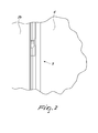
Figure 2 is a detail of the guide of the door shown inFigure 1 ; -
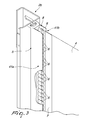
Figure 3 is a partially cutaway detail showing the sliding of the teeth in the guide; -
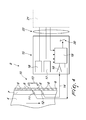
Figure 4 is a schematic view of the device; -
Figure 5 is a sectional view of a particular solution for the device. - In the embodiments hereinbelow, individual characteristics shown in relation to specific examples may in reality be interchanged with other, different characteristics, existing in other embodiments.
- Moreover, it should be noted that anything found to be already known during the patenting process is understood not to be claimed and to be the subject of a disclaimer.
- With reference to the figures, the reference numeral 1 designates a fast roll-up door constituted basically by two
vertical posts horizontal beam 3, containing a take-up roller (not shown) to which a gear motor is connected for its movement (not shown). - The closing element of the door is implemented with a
curtain 4, usually constituted by a polyester fabric spread on both sides with PVC that is wound around the roller and slides laterally withinspecial guides 5 fixed to theposts - A plurality of
teeth 6, which are identical and mutually equidistant with a selected spacing, protrudes laterally to thecurtain 4. - In the particular embodiment these
teeth 6 are obtained by injection moulding on aribbon 7, preferably made of textile material. - For moulding the
teeth 6, advantageously the technology used to obtain zip fasteners can be utilized. - The
ribbon 7 is connected preferably at both the vertical sides of thecurtain 4, preferably by means of welding or stitching. - The
teeth 6 are arranged laterally to and outside theribbon 7, and all are arranged in parallel with each other and can be accommodated at an adaptedseat 8 provided axially at eachguide 5. - The shape of the
teeth 6 and of theseat 8 are such that the teeth can slide freely and axially inside theguide 5, and it is also possible for them to exit temporarily and transversely from theguide 5 when for example a force that exceeds preset values, due substantially to accidental impacts that are made to bear on thecurtain 4 for example by personnel or by a trolley or by a vehicle, is applied on thecurtain 4. - Thus the
teeth 6 are provided, at the ends, with curved shapes adapted to allow their temporary extraction and their subsequent reinsertion into theguide 5, the reinsertion occurring by way of known means arranged at or in proximity to the upper end of theguides 5. - The shape of the
teeth 6 and of theguides 5 is in any case such as to keep, during the normal use of the door, theteeth 6 inside theseat 8 and thus inside theguides 5, this condition being maintained for preset values of forces that are applied on thecurtain 4 such as, for example, a pressure exerted by the wind. - This shape must also allow the
teeth 6 to exit transversely to theguide 5 when the thrust on thecurtain 4 exceeds preset values, in order to prevent the curtain from being subjected to permanent damage for example in the event of accidental impacts thereon. - The
reference numeral 9 generally designates the device for detecting the speed of the curtain, this device exploiting the shape of theteeth 6 provided on the lateral edge of thecurtain 4 due to the fact that the teeth provide a sequence of solids and spaces at a constant spacing. - In the particular embodiment, the
device 9 comprisesoptoelectronic means 10 adapted to count the sequence, over time, of the solids and spaces formed by the teeth during the vertical movement of thecurtain 4, these optoelectronic means thus being capable of detecting the instantaneous speed of the curtain. - By establishing beforehand the speed values of the curtain which are associated with its normal operation, any anomalies with respect to that operation can be determined so that the device can generate determined actions, as will be specified below.
- Thus, the optoelectronic means 10 comprise a pulsed
infrared emitter 11 and aphotodiode 12 which are arranged on the sameouter side wall 41a of the guide, at a suitable distance between them. - On the other side, on the
outer side wall 41b of theguide 5, afirst light guide 13 is provided, which is transparent to infrared and based on the principle of total internal reflection. - The positioning of the
emitter 11, of thephotodiode 12, and of thefirst light guide 13 is such that the passage of theteeth 6 and of the associated empty spaces that divide them will cause periodic interruptions in the path of the infrared light from the emitter to the receiver constituted by thephotodiode 12. - The
outgoing signal 14 from thephotodiode 12 is sent to an electronic processing means 15 which will perform at least one measurement of the speed of thecurtain 4. - The electronic processing means 15 is comprised of a
power supply circuit 16 that supplies the necessary voltages for the operation of the various components that make up the system, anadjustment assembly 17 that makes it possible to modify the sensitivity to the obstacle, acircuit 18 adapted to boost and process thesignal 14 coming from theoptoelectronic means 10, and adigital microcontroller 19 adapted to perform the calculation of the speed of thecurtain 4 and to detect the effects on speed produced by an obstacle. - Lastly, the electronic processing means 15 comprises an
output device 20 that opens its contact when an obstacle is detected or in the event of anomalies in operation. - The electronic processing means 15 is connected to a
control unit 21 of the door 1 by means of a series ofinterface signals 22. -
Figure 5 shows a preferential scheme for the optoelectronic means 10 for detecting the passage of theteeth 6. Theemitter 11 of infrared light is inserted within an adaptedfirst blackout bushing 23 which is interlocked at an adaptedcircular seat 24 provided axially with afirst biconvex lens 25 provided at the wall of acontainer 26, which is made of plastic material and transparent to infrared light, associated with the side wall of theguide 5. - The
emitter 11 produces a pulsed infrared light beam which is concentrated by the firstbiconvex lens 25 toward a second,transparent light guide 27 inserted at an adaptedfirst hole 40a provided on theouter side wall 41a of theguide 5. - The infrared light beam exiting from the
second light guide 27 passes through the space constituted by theseat 8 for theteeth 6 and is thus periodically interrupted by the passage of theteeth 6 during the vertical movement of thecurtain 4. - The light beam thus arrives at the
first light guide 13 which is C-shaped and comprised of three straight sections adapted to form the three sides of a rectangle and associated at the two ends at adapted second andthird holes other side wall 41b of theguide 5. One of these ends is arranged in axial alignment with thesecond light guide 27 and the other in axial alignment with athird light guide 28 which is arranged in front of thephotodiode 12 at an adaptedfourth hole 40d provided on theouter side wall 41a of theguide 5. - The light beam thus passes twice through the
seat 8 where theteeth 6 slide. - Here also, the
photodiode 12 is positioned at asecond bushing 29 positioned at an adaptedcircular seat 30 directed toward thecontainer 26, asecond biconvex lens 31 being provided within it. - The
photodiode 12 will generate a pulsed current as output during the moment when the infrared light beam passes through an empty space between twoteeth 6 of thecurtain 4, and a zero current during the moments when the infrared light beam is interrupted by the presence of one of theteeth 6. - Thus the operation ensures that, thanks to the presence of a sequence of teeth at a constant spacing on the lateral edge of the curtain, the device, which can be positioned indifferently on one side only or on both sides of the door, detects the speed of the curtain and manages it, by means of specific software, so as to cause the reopening, in the event of abrupt slowdowns, for example associated with the impact of the lower edge of the curtain on an obstacle or more generally with a sudden interruption of the movement of the curtain, due for example to gusts of wind.
- The device is in fact capable of identifying the position of the curtain and thus of managing different speeds as a function of the position of the curtain.
- In practice it has been found that the invention fully achieves the above-mentioned aim and objects since it makes it possible to identify abrupt slowdowns in the closing step of the curtain, due for example to impacts of the lower edge on an obstacle, and to consequently cause a reopening/stopping manoeuvre of the curtain.
- Moreover the invention makes it possible to utilize a curtain without rigid elements which could be subjected to permanent deformations/breakages.
- The invention also makes it possible to achieve the reopening by impact on the lower edge of the curtain in the absence of one or more sensitive elements arranged on a rigid lower edge of the curtain.
- Obviously the materials used as well as the dimensions constituting the individual components of the invention can be more pertinent to specific requirements.
- The various means for effecting certain different functions shall not in any way coexist only in the illustrated embodiment, but may be present per se in many embodiments, even if they are not illustrated.
- The characteristics indicated as advantageous, advisable or similar may also be lacking or be substituted by equivalent characteristics.
- The disclosures in Italian Patent Application No.
TV2010A000135 - Where technical features mentioned in any claim are followed by reference signs, those reference signs have been included for the sole purpose of increasing the intelligibility of the claims and accordingly, such reference signs do not have any limiting effect on the interpretation of each element identified by way of example by such reference signs.
Claims (10)
- A device (9) for detecting the speed of the curtain, which can slide in a vertical direction within a guide of a fast roll-up door, characterized in that a plurality of mutually equidistant teeth (6) protrude transversely and laterally to a curtain (4), said device comprising means (10) adapted to detect, during the motion of said curtain, the time sequence of said teeth (6) and to control the movement of said curtain (4).
- The device according to claim 1, characterized in that said plurality of teeth slides freely and axially within said guide during normal use, said plurality of teeth being allowed to exit temporarily and transversely from said guide when a force that exceeds preset values, due substantially to accidental impacts on said curtain, is applied on said curtain.
- The device according to claims 1 and 2, characterized in that said plurality of teeth (6) are obtained by injection molding on a ribbon (7) which is associated to one or both of the vertical sides of said curtain (4).
- The device according to claims 1 and 3, characterized in that said teeth (6) have, at their ends, curved shapes which are adapted to allow their temporary extraction and their subsequent reinsertion in said guide (5), said reinsertion occurring by means which are arranged at or proximate to the upper end of said guides (5), the shape of said teeth (6) and of said guides (6) being such as to keep, during normal use of the door, said teeth (6) within said seat (8) and within said guides (5), this condition being maintained for preset values of forces that are exerted on said curtain (4) and at the same time being adapted to allow said teeth (6) also to exit transversely to said guide (5) when the thrust on said curtain (4) exceeds preset values.
- The device according to one or more of the preceding claims, characterized in that said means (10) adapted to detect the time sequence of said teeth and to control the movement of said curtain comprises an optoelectronic means (10) which is adapted to count the sequence over time of the fills and voids defined by said teeth (6) during the vertical movement of said curtain (4) and to determine/control, once the speed values of said curtain that can be associated with its normal operation have been established beforehand, any anomalies with respect to said operation and to generate specific actions aimed at modifying the movement of said curtain.
- The device according to claim 5, characterized in that said optoelectronic means (10) comprises a pulsed infrared emitter (11) and a photodiode (12), which are arranged at the same outer side wall (41a) of at least one of said guides (5), at a mutual distance.
- The device according to claim 6, characterized in that on the opposite side, on the outer side wall (41b) of said guide (5), a first light guide (13) is associated which is transparent to infrared and is based on the principle of total internal reflection so as to redirect the beam of light from said emitter (11) to said photodiode (12).
- The device according to one or more of the preceding claims, characterized in that the signal (14) that exits from said photodiode (12) is sent to an electronic processing means (15), which performs at least one measurement of the speed of said curtain (4), said electronic processing means (15) being composed of a power supply circuit (16), which delivers the voltages required for the operation of the various components that form the system, an adjustment assembly (17), which makes it possible to modify the sensitivity to the obstacle, a circuit (18), which is adapted to boost and process the signal (14) that arrives from the optoelectronic means (10), a digital microcontroller (19), which is adapted to calculate the speed of said curtain (4) and to detect the effects on speed caused by an obstacle, and an output device (20), which opens its contact when an obstacle is detected or in the event of anomalies in operation, said electronic processing means (15) being connected to a control unit (21) of said door (1) by means of a series of interface signals (22).
- The device according to one or more of the preceding claims, characterized in that said emitter (11) of infrared light and said photodiode (12) are inserted within first and second blackout bushing (23, 29) which are interlocked at an adapted circular seat (24, 30), said bushings being provided respectively and axially with a first biconvex lens and a second biconvex lens (25, 31), which are provided at the wall of a container (26), made of a plastic material that is transparent to infrared light, associated with a side wall of said guide (5).
- The device according to claims 1 and 9, characterized in that said emitter (11) generates a pulsed infrared light beam, which is concentrated by said first biconvex lens (25) toward a second transparent light guide (27), which is inserted at an adapted first hole (40a) provided on the outer side wall (41a) of said guide (5), said infrared light beam that exits from said second light guide (27) passing through the space constituted by said seat (8) for said teeth (6) and being interrupted periodically by the passage of said teeth (6) during the vertical motion of said curtain (4), said beam of light subsequently reaching said first light guide (13), which is C-shaped and composed of three straight sections adapted to form the three sides of a rectangle, and is associated at the two ends at adapted second and third holes (40b, 40c) provided in the other side wall (41b) of said guide (5), said ends being arranged respectively in axial alignment with said second light guide (27) and in axial alignment with a third light guide (28), which is arranged in front of said photodiode (12) at an adapted fourth hole (40d) provided in the outer side wall (41a) of said guide (5).
Priority Applications (1)
| Application Number | Priority Date | Filing Date | Title |
|---|---|---|---|
| PL11184171T PL2441911T3 (en) | 2010-10-13 | 2011-10-06 | Device for detecting the speed of the curtain of a fast roll-up door |
Applications Claiming Priority (1)
| Application Number | Priority Date | Filing Date | Title |
|---|---|---|---|
| ITTV2010A000135A IT1402346B1 (en) | 2010-10-13 | 2010-10-13 | DEVICE FOR DETECTING THE SPEED OF A FAST DOOR WINDOW DOOR. |
Publications (2)
| Publication Number | Publication Date |
|---|---|
| EP2441911A1 true EP2441911A1 (en) | 2012-04-18 |
| EP2441911B1 EP2441911B1 (en) | 2015-08-19 |
Family
ID=43738415
Family Applications (1)
| Application Number | Title | Priority Date | Filing Date |
|---|---|---|---|
| EP11184171.4A Active EP2441911B1 (en) | 2010-10-13 | 2011-10-06 | Device for detecting the speed of the curtain of a fast roll-up door |
Country Status (5)
| Country | Link |
|---|---|
| EP (1) | EP2441911B1 (en) |
| ES (1) | ES2550930T3 (en) |
| HU (1) | HUE026665T2 (en) |
| IT (1) | IT1402346B1 (en) |
| PL (1) | PL2441911T3 (en) |
Cited By (7)
| Publication number | Priority date | Publication date | Assignee | Title |
|---|---|---|---|---|
| WO2014168748A3 (en) * | 2013-04-12 | 2014-12-24 | Rite-Hite Holding Corporation | Systems and methods to retain and refeed door curtains |
| WO2015121256A1 (en) * | 2014-02-12 | 2015-08-20 | Assa Abloy Entrance Systems Ab | Fast roll-up door comprising a curtain speed detection device |
| EP2848758A4 (en) * | 2012-05-11 | 2016-01-13 | Amiserru Sl | QUICK OPENING DOOR |
| US9493984B2 (en) | 2013-04-12 | 2016-11-15 | Rite-Hite Holding Corporation | Systems and methods to retain and refeed door curtains |
| JP2018105068A (en) * | 2016-12-28 | 2018-07-05 | セイキ住工株式会社 | Roll screen device |
| CN114651108A (en) * | 2019-09-09 | 2022-06-21 | 瑞泰控股公司 | Apparatus and method for door curtain detachment detection |
| EP4530429A1 (en) | 2023-09-27 | 2025-04-02 | Renson NV | System for automatically rolling up and unrolling a rollable screen |
Families Citing this family (3)
| Publication number | Priority date | Publication date | Assignee | Title |
|---|---|---|---|---|
| EP3887636B1 (en) * | 2018-11-30 | 2025-07-02 | Rytec Corporation | Door assembly with two drive sprockets and two corresponding drive guides |
| US12439864B2 (en) | 2019-09-16 | 2025-10-14 | Slide2Seal Ltd. | System and method for reversibly covering a zone |
| CN112252954A (en) * | 2020-10-30 | 2021-01-22 | 广东奥科伟业科技发展有限公司 | Precision light-adjusting roller shutter system |
Citations (3)
| Publication number | Priority date | Publication date | Assignee | Title |
|---|---|---|---|---|
| FR2518630A1 (en) * | 1981-12-23 | 1983-06-24 | Yoshida Kogyo Kk | APPARATUS FOR CONTROLLING THE OPERATION OF AN AUTOMATIC DOOR WITH MINIMUM ERROR IN THE DETECTED POSITION OF THIS DOOR |
| DE102005003794A1 (en) * | 2005-01-26 | 2006-08-03 | Cedes Ag | Gate, e.g. rolling gate, protecting device, has light barriers between which distance transfers another light barrier in measuring state if gate is in path between another two of barriers and before gate reaches former barrier |
| WO2009090097A2 (en) * | 2008-01-16 | 2009-07-23 | Cedes Ag | Safety system for safeguarding a moving, guided motion element against unwanted collisions |
-
2010
- 2010-10-13 IT ITTV2010A000135A patent/IT1402346B1/en active
-
2011
- 2011-10-06 EP EP11184171.4A patent/EP2441911B1/en active Active
- 2011-10-06 PL PL11184171T patent/PL2441911T3/en unknown
- 2011-10-06 HU HUE11184171A patent/HUE026665T2/en unknown
- 2011-10-06 ES ES11184171.4T patent/ES2550930T3/en active Active
Patent Citations (3)
| Publication number | Priority date | Publication date | Assignee | Title |
|---|---|---|---|---|
| FR2518630A1 (en) * | 1981-12-23 | 1983-06-24 | Yoshida Kogyo Kk | APPARATUS FOR CONTROLLING THE OPERATION OF AN AUTOMATIC DOOR WITH MINIMUM ERROR IN THE DETECTED POSITION OF THIS DOOR |
| DE102005003794A1 (en) * | 2005-01-26 | 2006-08-03 | Cedes Ag | Gate, e.g. rolling gate, protecting device, has light barriers between which distance transfers another light barrier in measuring state if gate is in path between another two of barriers and before gate reaches former barrier |
| WO2009090097A2 (en) * | 2008-01-16 | 2009-07-23 | Cedes Ag | Safety system for safeguarding a moving, guided motion element against unwanted collisions |
Cited By (18)
| Publication number | Priority date | Publication date | Assignee | Title |
|---|---|---|---|---|
| EP2848758A4 (en) * | 2012-05-11 | 2016-01-13 | Amiserru Sl | QUICK OPENING DOOR |
| US9493984B2 (en) | 2013-04-12 | 2016-11-15 | Rite-Hite Holding Corporation | Systems and methods to retain and refeed door curtains |
| WO2014168748A3 (en) * | 2013-04-12 | 2014-12-24 | Rite-Hite Holding Corporation | Systems and methods to retain and refeed door curtains |
| US9222304B2 (en) | 2013-04-12 | 2015-12-29 | Rite-Hite Holding Corporation | Systems and methods to retain and refeed door curtains |
| EP3128114A1 (en) * | 2013-04-12 | 2017-02-08 | Rite-Hite Holding Corporation | Control apparatus to retain and refeed door curtains |
| US9714540B2 (en) | 2014-02-12 | 2017-07-25 | Assa Abloy Entrance Systems Ab | Fast roll-up door comprising a curtain speed detection device |
| CN106030015A (en) * | 2014-02-12 | 2016-10-12 | 亚萨合莱自动门系统有限公司 | Fast roll-up door comprising a curtain speed detection device |
| JP2017508086A (en) * | 2014-02-12 | 2017-03-23 | アッサ・アブロイ・エントランス・システムズ・アーベー | High-speed roll-up door with curtain speed detection device |
| WO2015121256A1 (en) * | 2014-02-12 | 2015-08-20 | Assa Abloy Entrance Systems Ab | Fast roll-up door comprising a curtain speed detection device |
| CN106030015B (en) * | 2014-02-12 | 2018-04-27 | 亚萨合莱自动门系统有限公司 | Fast rolling doors including shutter speed detection |
| RU2675716C2 (en) * | 2014-02-12 | 2018-12-24 | Асса Аблой Энтранс Системс АБ | Fast roll-up door comprising curtain speed detection device |
| JP2018105068A (en) * | 2016-12-28 | 2018-07-05 | セイキ住工株式会社 | Roll screen device |
| CN114651108A (en) * | 2019-09-09 | 2022-06-21 | 瑞泰控股公司 | Apparatus and method for door curtain detachment detection |
| US11708722B2 (en) | 2019-09-09 | 2023-07-25 | Rite-Hite Holding Corporation | Apparatus and methods for door curtain breakaway detection |
| CN114651108B (en) * | 2019-09-09 | 2024-04-09 | 瑞泰控股公司 | Device and method for detecting door curtain detachment |
| US12006767B2 (en) | 2019-09-09 | 2024-06-11 | Rite-Hite Holding Corporation | Apparatus and methods for door curtain breakaway detection |
| EP4530429A1 (en) | 2023-09-27 | 2025-04-02 | Renson NV | System for automatically rolling up and unrolling a rollable screen |
| BE1032010A1 (en) | 2023-09-27 | 2025-04-23 | Renson | System for automatically rolling up and down a roll-up screen |
Also Published As
| Publication number | Publication date |
|---|---|
| ES2550930T3 (en) | 2015-11-13 |
| EP2441911B1 (en) | 2015-08-19 |
| ITTV20100135A1 (en) | 2012-04-14 |
| HUE026665T2 (en) | 2016-07-28 |
| IT1402346B1 (en) | 2013-08-30 |
| PL2441911T3 (en) | 2016-01-29 |
Similar Documents
| Publication | Publication Date | Title |
|---|---|---|
| EP2441911B1 (en) | Device for detecting the speed of the curtain of a fast roll-up door | |
| US11236540B2 (en) | System and method for safety management in roll-up doors | |
| RU2675716C2 (en) | Fast roll-up door comprising curtain speed detection device | |
| JP5764284B2 (en) | Automatic door device | |
| BG64001B1 (en) | Device and method for feeding foil materials | |
| EP3310986B1 (en) | Door curtains with position sensor switches | |
| DK2925947T3 (en) | Roller door with a door plate in the form of a flexible curtain. | |
| US11072516B2 (en) | Safety apparatus for an escalator and an escalator comprising the safety apparatus | |
| US11378161B2 (en) | Monitoring system for operating an energy chain | |
| JP2016159796A (en) | Rope type platform safety fence | |
| US10280045B2 (en) | Human transport device having a monitoring apparatus | |
| JP6699565B2 (en) | Elevator position detector | |
| IT9067387A1 (en) | PROCEDURE AND DEVICE TO DETECT THE POSITION OF CONVEYED ITEMS, PARTICULARLY FOR AUTOMATIC PACKAGING SYSTEMS | |
| KR101133449B1 (en) | Apparatus for shading installed at outside window | |
| JP6123890B2 (en) | Elevator door control device | |
| JP5567101B2 (en) | Passenger conveyor | |
| ITBO20110439A1 (en) | MOTORIZED CURTAIN GROUP | |
| CN218057773U (en) | Cutting machine guide deviation correcting device | |
| WO2016002440A1 (en) | Door control device for elevator | |
| CN220787673U (en) | Cotton guide ring and textile equipment | |
| ITRM980173A1 (en) | PROCEDINENT FOR ADJUSTING THE NUMBER OF REVOLUTIONS OF A REGULATED DISPENSING TANK ROTATING ON A HORIZONTAL PLANE FOR | |
| IT202000015088A1 (en) | FAST-SLIDING ROLLER DOOR INCLUDING AN UPPER RECEPTION AREA TO ACCOMMODATE A FLEXIBLE FRAME IN OPEN DOOR CONFIGURATION | |
| KR101510560B1 (en) | Cutting slant sensor system of fiber loom | |
| CN111118727A (en) | Yarn conveying device for detecting yarn scab | |
| CN104843542A (en) | Storage yarn feeder with rotary drum and yarn-unwinding sensor |
Legal Events
| Date | Code | Title | Description |
|---|---|---|---|
| PUAI | Public reference made under article 153(3) epc to a published international application that has entered the european phase |
Free format text: ORIGINAL CODE: 0009012 |
|
| AK | Designated contracting states |
Kind code of ref document: A1 Designated state(s): AL AT BE BG CH CY CZ DE DK EE ES FI FR GB GR HR HU IE IS IT LI LT LU LV MC MK MT NL NO PL PT RO RS SE SI SK SM TR |
|
| AX | Request for extension of the european patent |
Extension state: BA ME |
|
| 17P | Request for examination filed |
Effective date: 20121009 |
|
| GRAP | Despatch of communication of intention to grant a patent |
Free format text: ORIGINAL CODE: EPIDOSNIGR1 |
|
| INTG | Intention to grant announced |
Effective date: 20150324 |
|
| GRAS | Grant fee paid |
Free format text: ORIGINAL CODE: EPIDOSNIGR3 |
|
| RAP1 | Party data changed (applicant data changed or rights of an application transferred) |
Owner name: ASSA ABLOY ENTRANCE SYSTEM AB |
|
| GRAA | (expected) grant |
Free format text: ORIGINAL CODE: 0009210 |
|
| AK | Designated contracting states |
Kind code of ref document: B1 Designated state(s): AL AT BE BG CH CY CZ DE DK EE ES FI FR GB GR HR HU IE IS IT LI LT LU LV MC MK MT NL NO PL PT RO RS SE SI SK SM TR |
|
| RAP1 | Party data changed (applicant data changed or rights of an application transferred) |
Owner name: ASSA ABLOY ENTRANCE SYSTEMS AB |
|
| REG | Reference to a national code |
Ref country code: GB Ref legal event code: FG4D |
|
| REG | Reference to a national code |
Ref country code: CH Ref legal event code: EP |
|
| REG | Reference to a national code |
Ref country code: IE Ref legal event code: FG4D |
|
| REG | Reference to a national code |
Ref country code: AT Ref legal event code: REF Ref document number: 743965 Country of ref document: AT Kind code of ref document: T Effective date: 20150915 |
|
| REG | Reference to a national code |
Ref country code: FR Ref legal event code: PLFP Year of fee payment: 5 |
|
| REG | Reference to a national code |
Ref country code: DE Ref legal event code: R096 Ref document number: 602011018870 Country of ref document: DE |
|
| REG | Reference to a national code |
Ref country code: NL Ref legal event code: FP |
|
| REG | Reference to a national code |
Ref country code: ES Ref legal event code: FG2A Ref document number: 2550930 Country of ref document: ES Kind code of ref document: T3 Effective date: 20151113 |
|
| REG | Reference to a national code |
Ref country code: SE Ref legal event code: TRGR |
|
| REG | Reference to a national code |
Ref country code: AT Ref legal event code: MK05 Ref document number: 743965 Country of ref document: AT Kind code of ref document: T Effective date: 20150819 |
|
| REG | Reference to a national code |
Ref country code: LT Ref legal event code: MG4D |
|
| PG25 | Lapsed in a contracting state [announced via postgrant information from national office to epo] |
Ref country code: FI Free format text: LAPSE BECAUSE OF FAILURE TO SUBMIT A TRANSLATION OF THE DESCRIPTION OR TO PAY THE FEE WITHIN THE PRESCRIBED TIME-LIMIT Effective date: 20150819 Ref country code: LV Free format text: LAPSE BECAUSE OF FAILURE TO SUBMIT A TRANSLATION OF THE DESCRIPTION OR TO PAY THE FEE WITHIN THE PRESCRIBED TIME-LIMIT Effective date: 20150819 Ref country code: NO Free format text: LAPSE BECAUSE OF FAILURE TO SUBMIT A TRANSLATION OF THE DESCRIPTION OR TO PAY THE FEE WITHIN THE PRESCRIBED TIME-LIMIT Effective date: 20151119 Ref country code: GR Free format text: LAPSE BECAUSE OF FAILURE TO SUBMIT A TRANSLATION OF THE DESCRIPTION OR TO PAY THE FEE WITHIN THE PRESCRIBED TIME-LIMIT Effective date: 20151120 Ref country code: LT Free format text: LAPSE BECAUSE OF FAILURE TO SUBMIT A TRANSLATION OF THE DESCRIPTION OR TO PAY THE FEE WITHIN THE PRESCRIBED TIME-LIMIT Effective date: 20150819 |
|
| PG25 | Lapsed in a contracting state [announced via postgrant information from national office to epo] |
Ref country code: RS Free format text: LAPSE BECAUSE OF FAILURE TO SUBMIT A TRANSLATION OF THE DESCRIPTION OR TO PAY THE FEE WITHIN THE PRESCRIBED TIME-LIMIT Effective date: 20150819 Ref country code: PT Free format text: LAPSE BECAUSE OF FAILURE TO SUBMIT A TRANSLATION OF THE DESCRIPTION OR TO PAY THE FEE WITHIN THE PRESCRIBED TIME-LIMIT Effective date: 20151221 Ref country code: AT Free format text: LAPSE BECAUSE OF FAILURE TO SUBMIT A TRANSLATION OF THE DESCRIPTION OR TO PAY THE FEE WITHIN THE PRESCRIBED TIME-LIMIT Effective date: 20150819 Ref country code: IS Free format text: LAPSE BECAUSE OF FAILURE TO SUBMIT A TRANSLATION OF THE DESCRIPTION OR TO PAY THE FEE WITHIN THE PRESCRIBED TIME-LIMIT Effective date: 20151219 |
|
| PG25 | Lapsed in a contracting state [announced via postgrant information from national office to epo] |
Ref country code: SK Free format text: LAPSE BECAUSE OF FAILURE TO SUBMIT A TRANSLATION OF THE DESCRIPTION OR TO PAY THE FEE WITHIN THE PRESCRIBED TIME-LIMIT Effective date: 20150819 Ref country code: DK Free format text: LAPSE BECAUSE OF FAILURE TO SUBMIT A TRANSLATION OF THE DESCRIPTION OR TO PAY THE FEE WITHIN THE PRESCRIBED TIME-LIMIT Effective date: 20150819 Ref country code: EE Free format text: LAPSE BECAUSE OF FAILURE TO SUBMIT A TRANSLATION OF THE DESCRIPTION OR TO PAY THE FEE WITHIN THE PRESCRIBED TIME-LIMIT Effective date: 20150819 |
|
| REG | Reference to a national code |
Ref country code: DE Ref legal event code: R097 Ref document number: 602011018870 Country of ref document: DE |
|
| PG25 | Lapsed in a contracting state [announced via postgrant information from national office to epo] |
Ref country code: RO Free format text: LAPSE BECAUSE OF FAILURE TO SUBMIT A TRANSLATION OF THE DESCRIPTION OR TO PAY THE FEE WITHIN THE PRESCRIBED TIME-LIMIT Effective date: 20150819 Ref country code: LU Free format text: LAPSE BECAUSE OF FAILURE TO SUBMIT A TRANSLATION OF THE DESCRIPTION OR TO PAY THE FEE WITHIN THE PRESCRIBED TIME-LIMIT Effective date: 20151006 |
|
| REG | Reference to a national code |
Ref country code: CH Ref legal event code: PL |
|
| PLBE | No opposition filed within time limit |
Free format text: ORIGINAL CODE: 0009261 |
|
| STAA | Information on the status of an ep patent application or granted ep patent |
Free format text: STATUS: NO OPPOSITION FILED WITHIN TIME LIMIT |
|
| PG25 | Lapsed in a contracting state [announced via postgrant information from national office to epo] |
Ref country code: MC Free format text: LAPSE BECAUSE OF FAILURE TO SUBMIT A TRANSLATION OF THE DESCRIPTION OR TO PAY THE FEE WITHIN THE PRESCRIBED TIME-LIMIT Effective date: 20150819 |
|
| 26N | No opposition filed |
Effective date: 20160520 |
|
| REG | Reference to a national code |
Ref country code: IE Ref legal event code: MM4A |
|
| REG | Reference to a national code |
Ref country code: HU Ref legal event code: AG4A Ref document number: E026665 Country of ref document: HU |
|
| PG25 | Lapsed in a contracting state [announced via postgrant information from national office to epo] |
Ref country code: LI Free format text: LAPSE BECAUSE OF NON-PAYMENT OF DUE FEES Effective date: 20151031 Ref country code: CH Free format text: LAPSE BECAUSE OF NON-PAYMENT OF DUE FEES Effective date: 20151031 |
|
| PG25 | Lapsed in a contracting state [announced via postgrant information from national office to epo] |
Ref country code: SI Free format text: LAPSE BECAUSE OF FAILURE TO SUBMIT A TRANSLATION OF THE DESCRIPTION OR TO PAY THE FEE WITHIN THE PRESCRIBED TIME-LIMIT Effective date: 20150819 |
|
| REG | Reference to a national code |
Ref country code: FR Ref legal event code: PLFP Year of fee payment: 6 |
|
| PG25 | Lapsed in a contracting state [announced via postgrant information from national office to epo] |
Ref country code: IE Free format text: LAPSE BECAUSE OF NON-PAYMENT OF DUE FEES Effective date: 20151006 |
|
| PG25 | Lapsed in a contracting state [announced via postgrant information from national office to epo] |
Ref country code: BE Free format text: LAPSE BECAUSE OF FAILURE TO SUBMIT A TRANSLATION OF THE DESCRIPTION OR TO PAY THE FEE WITHIN THE PRESCRIBED TIME-LIMIT Effective date: 20150819 |
|
| PG25 | Lapsed in a contracting state [announced via postgrant information from national office to epo] |
Ref country code: SM Free format text: LAPSE BECAUSE OF FAILURE TO SUBMIT A TRANSLATION OF THE DESCRIPTION OR TO PAY THE FEE WITHIN THE PRESCRIBED TIME-LIMIT Effective date: 20150819 Ref country code: BG Free format text: LAPSE BECAUSE OF FAILURE TO SUBMIT A TRANSLATION OF THE DESCRIPTION OR TO PAY THE FEE WITHIN THE PRESCRIBED TIME-LIMIT Effective date: 20150819 |
|
| PG25 | Lapsed in a contracting state [announced via postgrant information from national office to epo] |
Ref country code: CY Free format text: LAPSE BECAUSE OF FAILURE TO SUBMIT A TRANSLATION OF THE DESCRIPTION OR TO PAY THE FEE WITHIN THE PRESCRIBED TIME-LIMIT Effective date: 20150819 |
|
| PG25 | Lapsed in a contracting state [announced via postgrant information from national office to epo] |
Ref country code: HR Free format text: LAPSE BECAUSE OF FAILURE TO SUBMIT A TRANSLATION OF THE DESCRIPTION OR TO PAY THE FEE WITHIN THE PRESCRIBED TIME-LIMIT Effective date: 20150819 |
|
| PG25 | Lapsed in a contracting state [announced via postgrant information from national office to epo] |
Ref country code: MT Free format text: LAPSE BECAUSE OF FAILURE TO SUBMIT A TRANSLATION OF THE DESCRIPTION OR TO PAY THE FEE WITHIN THE PRESCRIBED TIME-LIMIT Effective date: 20150819 |
|
| REG | Reference to a national code |
Ref country code: FR Ref legal event code: PLFP Year of fee payment: 7 |
|
| PG25 | Lapsed in a contracting state [announced via postgrant information from national office to epo] |
Ref country code: MK Free format text: LAPSE BECAUSE OF FAILURE TO SUBMIT A TRANSLATION OF THE DESCRIPTION OR TO PAY THE FEE WITHIN THE PRESCRIBED TIME-LIMIT Effective date: 20150819 |
|
| REG | Reference to a national code |
Ref country code: FR Ref legal event code: PLFP Year of fee payment: 8 |
|
| PG25 | Lapsed in a contracting state [announced via postgrant information from national office to epo] |
Ref country code: AL Free format text: LAPSE BECAUSE OF FAILURE TO SUBMIT A TRANSLATION OF THE DESCRIPTION OR TO PAY THE FEE WITHIN THE PRESCRIBED TIME-LIMIT Effective date: 20150819 |
|
| REG | Reference to a national code |
Ref country code: DE Ref legal event code: R082 Ref document number: 602011018870 Country of ref document: DE Representative=s name: SCHIEBER - FARAGO PATENTANWAELTE, DE Ref country code: DE Ref legal event code: R082 Ref document number: 602011018870 Country of ref document: DE Representative=s name: FARAGO PATENTANWALTSGESELLSCHAFT MBH, DE |
|
| REG | Reference to a national code |
Ref country code: DE Ref legal event code: R082 Ref document number: 602011018870 Country of ref document: DE Representative=s name: SCHIEBER - FARAGO PATENTANWAELTE, DE |
|
| P01 | Opt-out of the competence of the unified patent court (upc) registered |
Effective date: 20230531 |
|
| PGFP | Annual fee paid to national office [announced via postgrant information from national office to epo] |
Ref country code: PL Payment date: 20250912 Year of fee payment: 15 Ref country code: IT Payment date: 20250922 Year of fee payment: 15 Ref country code: NL Payment date: 20250912 Year of fee payment: 15 |
|
| PGFP | Annual fee paid to national office [announced via postgrant information from national office to epo] |
Ref country code: GB Payment date: 20250911 Year of fee payment: 15 |
|
| PGFP | Annual fee paid to national office [announced via postgrant information from national office to epo] |
Ref country code: FR Payment date: 20250922 Year of fee payment: 15 |
|
| PGFP | Annual fee paid to national office [announced via postgrant information from national office to epo] |
Ref country code: SE Payment date: 20250910 Year of fee payment: 15 |
|
| PGFP | Annual fee paid to national office [announced via postgrant information from national office to epo] |
Ref country code: CZ Payment date: 20250929 Year of fee payment: 15 |
|
| PGFP | Annual fee paid to national office [announced via postgrant information from national office to epo] |
Ref country code: HU Payment date: 20250929 Year of fee payment: 15 |
|
| PGFP | Annual fee paid to national office [announced via postgrant information from national office to epo] |
Ref country code: DE Payment date: 20250910 Year of fee payment: 15 |
|
| PGFP | Annual fee paid to national office [announced via postgrant information from national office to epo] |
Ref country code: TR Payment date: 20251002 Year of fee payment: 15 |
|
| PGFP | Annual fee paid to national office [announced via postgrant information from national office to epo] |
Ref country code: ES Payment date: 20251105 Year of fee payment: 15 |