EP2441888A2 - Self-propelled construction vehicle - Google Patents
Self-propelled construction vehicle Download PDFInfo
- Publication number
- EP2441888A2 EP2441888A2 EP11008191A EP11008191A EP2441888A2 EP 2441888 A2 EP2441888 A2 EP 2441888A2 EP 11008191 A EP11008191 A EP 11008191A EP 11008191 A EP11008191 A EP 11008191A EP 2441888 A2 EP2441888 A2 EP 2441888A2
- Authority
- EP
- European Patent Office
- Prior art keywords
- construction machine
- steering
- drives
- trajectory
- unit
- Prior art date
- Legal status (The legal status is an assumption and is not a legal conclusion. Google has not performed a legal analysis and makes no representation as to the accuracy of the status listed.)
- Granted
Links
- 238000010276 construction Methods 0.000 title claims description 139
- 238000001454 recorded image Methods 0.000 claims description 2
- 238000003801 milling Methods 0.000 description 13
- 238000010586 diagram Methods 0.000 description 3
- 230000001419 dependent effect Effects 0.000 description 1
- 230000000694 effects Effects 0.000 description 1
- 239000003381 stabilizer Substances 0.000 description 1
Images


Classifications
-
- E—FIXED CONSTRUCTIONS
- E01—CONSTRUCTION OF ROADS, RAILWAYS, OR BRIDGES
- E01C—CONSTRUCTION OF, OR SURFACES FOR, ROADS, SPORTS GROUNDS, OR THE LIKE; MACHINES OR AUXILIARY TOOLS FOR CONSTRUCTION OR REPAIR
- E01C23/00—Auxiliary devices or arrangements for constructing, repairing, reconditioning, or taking-up road or like surfaces
- E01C23/06—Devices or arrangements for working the finished surface; Devices for repairing or reconditioning the surface of damaged paving; Recycling in place or on the road
- E01C23/08—Devices or arrangements for working the finished surface; Devices for repairing or reconditioning the surface of damaged paving; Recycling in place or on the road for roughening or patterning; for removing the surface down to a predetermined depth high spots or material bonded to the surface, e.g. markings; for maintaining earth roads, clay courts or like surfaces by means of surface working tools, e.g. scarifiers, levelling blades
- E01C23/085—Devices or arrangements for working the finished surface; Devices for repairing or reconditioning the surface of damaged paving; Recycling in place or on the road for roughening or patterning; for removing the surface down to a predetermined depth high spots or material bonded to the surface, e.g. markings; for maintaining earth roads, clay courts or like surfaces by means of surface working tools, e.g. scarifiers, levelling blades using power-driven tools, e.g. vibratory tools
- E01C23/088—Rotary tools, e.g. milling drums
-
- B—PERFORMING OPERATIONS; TRANSPORTING
- B62—LAND VEHICLES FOR TRAVELLING OTHERWISE THAN ON RAILS
- B62D—MOTOR VEHICLES; TRAILERS
- B62D15/00—Steering not otherwise provided for
- B62D15/02—Steering position indicators ; Steering position determination; Steering aids
- B62D15/027—Parking aids, e.g. instruction means
- B62D15/0275—Parking aids, e.g. instruction means by overlaying a vehicle path based on present steering angle over an image without processing that image
-
- B—PERFORMING OPERATIONS; TRANSPORTING
- B62—LAND VEHICLES FOR TRAVELLING OTHERWISE THAN ON RAILS
- B62D—MOTOR VEHICLES; TRAILERS
- B62D7/00—Steering linkage; Stub axles or their mountings
- B62D7/06—Steering linkage; Stub axles or their mountings for individually-pivoted wheels, e.g. on king-pins
- B62D7/14—Steering linkage; Stub axles or their mountings for individually-pivoted wheels, e.g. on king-pins the pivotal axes being situated in more than one plane transverse to the longitudinal centre line of the vehicle, e.g. all-wheel steering
- B62D7/15—Steering linkage; Stub axles or their mountings for individually-pivoted wheels, e.g. on king-pins the pivotal axes being situated in more than one plane transverse to the longitudinal centre line of the vehicle, e.g. all-wheel steering characterised by means varying the ratio between the steering angles of the steered wheels
- B62D7/1509—Steering linkage; Stub axles or their mountings for individually-pivoted wheels, e.g. on king-pins the pivotal axes being situated in more than one plane transverse to the longitudinal centre line of the vehicle, e.g. all-wheel steering characterised by means varying the ratio between the steering angles of the steered wheels with different steering modes, e.g. crab-steering, or steering specially adapted for reversing of the vehicle
-
- E—FIXED CONSTRUCTIONS
- E01—CONSTRUCTION OF ROADS, RAILWAYS, OR BRIDGES
- E01C—CONSTRUCTION OF, OR SURFACES FOR, ROADS, SPORTS GROUNDS, OR THE LIKE; MACHINES OR AUXILIARY TOOLS FOR CONSTRUCTION OR REPAIR
- E01C19/00—Machines, tools or auxiliary devices for preparing or distributing paving materials, for working the placed materials, or for forming, consolidating, or finishing the paving
- E01C19/004—Devices for guiding or controlling the machines along a predetermined path
-
- E—FIXED CONSTRUCTIONS
- E02—HYDRAULIC ENGINEERING; FOUNDATIONS; SOIL SHIFTING
- E02F—DREDGING; SOIL-SHIFTING
- E02F9/00—Component parts of dredgers or soil-shifting machines, not restricted to one of the kinds covered by groups E02F3/00 - E02F7/00
- E02F9/20—Drives; Control devices
- E02F9/2058—Electric or electro-mechanical or mechanical control devices of vehicle sub-units
- E02F9/2087—Control of vehicle steering
-
- E—FIXED CONSTRUCTIONS
- E02—HYDRAULIC ENGINEERING; FOUNDATIONS; SOIL SHIFTING
- E02F—DREDGING; SOIL-SHIFTING
- E02F9/00—Component parts of dredgers or soil-shifting machines, not restricted to one of the kinds covered by groups E02F3/00 - E02F7/00
- E02F9/26—Indicating devices
Definitions
- the invention relates to a self-propelled construction machine, which has a chassis with front and rear wheels or drives in the working direction, which is supported by the chassis.
- the known self-propelled construction machines which include in particular the road milling machines, recyclers or stabilizers, have a working device for carrying out the construction measure.
- the working device may for example be a milling device, in particular a milling drum.
- Such construction machines differ from motor vehicles, in particular passenger cars, in that the construction machine can be steered both with the front wheels or drives and with the rear wheels or drives.
- the machine operator should be instructed by a second person when resetting. Nevertheless, the reset is difficult because the operator even the rear area can see only limited.
- construction machines which have a camera on the back and a screen on the control station. Although the machine operator of the construction machine can then see the rear area, but it can also be difficult to estimate with a camera, as the construction machine moves when resetting.
- driver assistance systems For motor vehicles, especially cars, devices are known that assisted the driver when parking the vehicle. Such devices are also referred to as driver assistance systems.
- the DE 103 34 613 A1 describes a device for motor vehicles, which indicates the range of motion of the vehicle on a screen, which is also referred to as a driving tube, depending on the chosen steering angle.
- a driver assistance system for towing vehicles with trailer is from the WO 2008/012109 A1 known.
- driver assistance systems for cars and trucks are not suitable for self-propelled construction machines that can be steered with both the front wheels or drives and with the rear wheels or drives. Also, the height adjustment with a longitudinal and transverse inclination of the machine frame makes special demands on a driver assistance system for self-propelled construction machines.
- the invention has for its object to provide a self-propelled construction machine that facilitates the machine operator reversing, especially for loading, attaching or parking the construction machine.
- the self-propelled construction machine is characterized by a device for assisting the operator when reversing, comprising a unit for detecting the position of the front wheels or drives and rear wheels or drives and a computing unit for determining data, the at least one trajectory of the construction machine in Depend on the position of the front wheels or drives and the rear wheels or drives.
- the device for assisting the machine operator has an image recording unit for recording an image of the rear area of the construction machine and a display unit for displaying the recorded image of the rear area of the construction machine.
- An image processing unit superimposes on the image of the rear area of the construction machine displayed on the display unit the representation of at least one trajectory with which the movement of the construction machine in the field or on traffic routes or areas is described.
- the device for assisting the operator when reversing considers both the position of the front and rear wheels or drives.
- One or more trajectories may be determined superimposed on the image of the rear of the construction machine.
- the operator can accurately estimate when reversing how the construction machine moves depending on the position of both the front and rear wheels or drives to possibly existing obstacles.
- the operating unit of the construction machine has both means for prescribing a steering angle for the front and / or rear wheels or drives as well as means for selecting a steering mode from a plurality of steering modes.
- the operating unit of the construction machine interacts with the steering device of the machine such that the steering device sets the predetermined steering angle or the selected steering mode.
- the arithmetic unit of the device for assisting the machine operator in reversing which determines the data describing at least one trajectory of the construction machine in dependence on the position of the front and rear wheels or drives, has in the preferred embodiment means for calculating at least the a Trajectory descriptive data not only in dependence on the position of the front and / or rear wheels or drives, but also in dependence on the selected steering mode.
- the operator can immediately recognize how the engine behaves when reversing.
- the operator can estimate what effects have different steering angles or steering modes. This makes it possible for the operator to not only better estimate the movement of the machine when reversing, but also to specify the optimum steering angle in optimum steering mode or vice versa.
- the means for calculating the data describing the at least one trajectory are formed in a particularly preferred embodiment such that the data describe the trajectory in the selected steering mode and the predetermined steering angle in a coordinate system related to the chassis of the construction machine.
- This coordinate system is preferably a coordinate system that does not change when the machine frame is adjusted in height with respect to the chassis with a predetermined lateral and / or longitudinal inclination.
- a preferred embodiment of the construction machine according to the invention assumes that the steering of the construction machine essentially satisfies the Ackermann law, so that the extension of the axes of the wheels or drives intersect at a curve center.
- the trajectories can be represented by circular arcs, which can be described by start and end point as well as a curve center and / or radius.
- the at least one trajectory is a straight line, which is the case with a steering in the same direction, the trajectory can be described solely by the start and end points.
- the arithmetic unit preferably has means for converting the data describing the at least one trajectory into a coordinate system related to the image recording unit, in which the image is displayed on the display unit. This makes it possible to select a different coordinate system for the image recording unit than the coordinate system of the construction machine. Consequently, the image recording unit can be arbitrarily arranged on the construction machine so as to be able to show the operator an image from a certain viewpoint.
- the machine frame is adjustable in height and / or inclination. It is advantageous if the correct representation of the at least one trajectory in the image of the rear area displayed on the display unit takes place independently of the height and / or inclination of the machine frame. Therefore, in another particularly preferred embodiment, the arithmetic unit comprises means for correcting the data describing the at least one trajectory in the coordinate system related to the image recording unit based on a correction function including a change in the pitch and / or bank angle and / or height of the image recording unit is taken into account with respect to the coordinate system related to the chassis of the construction machine.
- a change in the height and / or inclination of the machine frame relative to the coordinate system relative to the chassis of the construction machine also leads to a change in the height and / or inclination of the image recording unit arranged on the machine frame.
- the means for correcting the data describing the at least one trajectory ensure that a change in the height and / or inclination of the machine frame relative to the coordinate system related to the chassis of the construction machine does not lead to a false display of the at least one trajectory on the display unit.
- the data describing the at least one trajectory are thus transformed depending on the height and / or inclination of the machine frame so that they again match the image of the rear area that is displayed on the display unit.
- a particularly preferred embodiment provides means for correcting the data describing the at least one trajectory in the coordinate system related to the image recording unit on the basis of a correction function taking into account distortion of the image recorded by the image recording unit.
- the at least one trajectory is distorted as the image of the rear region is distorted.
- This particularly preferred embodiment has a relatively low computational power because it does not need to equalize the image, but only distorts the trajectory to show both representations on the display unit in correct relationship.
- the arithmetic unit has means for correcting the image of the rear area of the construction machine in the coordinate system related to the image recording unit on the basis of a correction function with which distortion of the image recorded by the image recording unit is corrected. For this purpose, however, a higher computing power is required.
- a trajectory is a trajectory that describes any point. This point can be on the construction machine to mark exactly one point of the machine, or even next to the machine to mark a safe distance from a point on the machine.
- the data describing the at least one trajectory may be different data.
- the trajectory can be described by a start and end point as well as a circle center or a radius.
- the distance between start and end point may be the vehicle length or part of the vehicle length.
- a plurality of trajectories are displayed, wherein one of the trajectories represents the vehicle length and the other trajectories represent parts of the vehicle length.
- the point should be at the extreme end of the rear of the machine to accommodate the When reversing, the operator should indicate the position of the stern.
- a trajectory for example, the movement of a point on the working device of the machine, for example the milling device, can be visualized.
- the trajectories can be displayed not only as lines between start and end points, but also as point clouds to visualize the movement of the construction machine on the display unit.
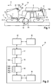
- Fig. 1 shows a road milling machine as an example of a self-propelled construction machine, which has a device to assist the operator when reversing.
- the road milling machine is a so-called large milling machine for milling road surfaces.
- the construction machine has a chassis 1 which has two front drives 2, 3 and two rear drives 4, 5 in the working direction I.
- the chassis can also have front and rear wheels.
- the drives are simply referred to as wheels.
- the chassis 1 carries a machine frame 6, which is adjustable by means of two front and two rear lifting columns 7, 8 in relation to the terrain or the traffic route or the traffic area in height, with the longitudinal and / or transverse inclination of the machine frame 6 is adjustable ,
- the construction machine has an unillustrated measuring device with which the position of the machine frame with respect to a reference plane, ie the height and inclination of the machine frame with respect to the reference plane, is detected.
- a measuring device is in the WO 2007/031531 A1 described.
- the construction machine has a non-illustrated drive means 9 for driving the front and rear wheels 2, 3; 4, 5 and a steering device 10 for steering the front and rear wheels 2, 3; 4, 5 and a milling device 19 with a milling drum 20 which is arranged between the front and rear wheels.
- control station 11 On the machine frame 6 is between front and rear wheels 2, 3; 4, 5 arranged the control station 11 of the construction machine.
- the driver's station can of course also be arranged at a different location, such. B. in front of the front wheels.
- the operating unit 12 has means 12A for prescribing a specific steering angle for the front and rear wheels 2, 3 and means 12B for selecting a specific steering mode.
- the means 12A for setting the steering angle may be a steering wheel 12A, while the means for selecting the steering mode may be a selector lever 12B. Steering wheel 12A and selector lever 12B are in Fig. 1 hinted at.
- the operating unit 12 cooperates with the steering device 10 as follows.
- the operator may select a particular steering mode from a plurality of steering modes with the select lever 12B.
- a steering mode called “coordinated steering” the construction machine with front and rear wheels 2, 3; 4, 5 directed in opposite directions, the front wheels 2 and 3 show the rear wheels in opposite directions.
- the operator chooses this steering mode if he wants to drive a tight radius.
- a steering mode called “crab steering” the construction machine is steered in the same direction as the front and rear wheels 2, 3, 4, 5, with the front wheels 2, 3 and the rear wheels 4, 5 pointing in the same direction If the construction machine is to travel laterally, the construction machine can also be steered only with the front wheels or only with the rear wheels.
- the operator only steers the construction machine with the steering wheel 12A.
- the rear wheels only the front wheels or both the front and rear wheels steered, in which case the front and rear wheels are steered either in the same direction or in opposite directions.
- the self-adjusting steering angle at the front and rear axles are predetermined by the geometry of the steering device, which will be explained below.
- Fig. 2 shows the block diagram of the device 13 for assisting the machine operator during reversing, which cooperates with the steering device 10 and the control unit 12 of the construction machine.
- the device 13 for assistance in reversing has a display unit 14, for example, arranged on the control station 12 screen (display) on which a picture of the rear Area of the construction machine is displayed together with one or more trajectories, with which the operator can estimate how the construction machine moves at a predetermined steering angle and the selected steering mode.
- the image of the rear portion of the construction machine is recorded with an image recording unit 15 having a camera 15A disposed at the rear of the machine frame.
- the camera 15A follows the movements of the machine frame 6 of the construction machine in relation to height and inclination relative to the terrain.
- the camera 15A is at the rear of the machine.
- the reversing assistance device 13 has a computing unit 16 with which the data describing at least one trajectory of the construction machine in dependence on the position of the front and rear wheels and in dependence on the steering mode are determined.
- the position of the front and rear wheels is detected by a unit 17, which may be part of the device 13 for assistance in reversing or part of the steering device 10.
- the block diagram of Fig. 2 shows the unit 17 as part of the device 13.
- the device 13 for assisting the machine operator has an image processing unit 18 which superimposes on the image of the rear area of the construction machine displayed on the display unit 14 the at least one trajectory which is determined by the arithmetic unit 16. Consequently, the operator sees both the at least one trajectory and the rear area of the construction machine on the display unit, so that the operator can associate the movement of the construction machine with the objects located in the field or on the traffic route.
- the at least one trajectory also more information can be displayed, such. For example, the distances.
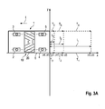
- FIGS. 3A to 3C show the simplest case where the construction machine goes straight backwards. Consequently, the steering angle ⁇ of the front and rear wheels 2, 3; 4, 5 zero.
- the chassis 1 is shown only schematically with the front and rear wheels. The representation takes place in a reference to the chassis of the construction machine coordinate system (x, y), which represents the reference plane. The position of the front and rear wheels 2, 3; 4, 5 is defined by the steering angle ⁇ .
- the machine frame 6 of the construction machine is represented in the coordinate system by a rectangle.
- the corner points of the rectangle correspond to the front and rear corner points of the machine.
- Between the front and rear wheels 2, 3; 4, 5 is the milling device 19 with the milling drum 20th
- the zero point (x0, y0) in the coordinate system related to the chassis of the machine lies on the rear left in the working direction I corner of the machine frame. 6
- the arithmetic unit 16 has means 16A which, for the representation of the backward movement of the construction machine in the present embodiment, calculate a total of six trajectories, which are each described by a starting point and an end point. Since the construction machine goes straight backwards, the trajectories are straight lines between the two points.
- the arithmetic unit calculates the coordinates (x3, y3) of the point in the vehicle Construction machine related coordinate system, where the rear left corner point of the machine frame is when the construction machine has reset by the vehicle length (l 1 ), for example 9 m. Accordingly, the arithmetic unit calculates the coordinates (x2, y2) or (x1, y1) at which the rear left vertex (x0, y0) of the construction machine is located when the construction machine by a shorter distance (l 2 or l 3 ) , For example, 3 m and 1 m, has reset.
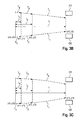
- the trajectories T 1 to T 6 in the coordinate system related to the landing gear of the construction machine do not correspond to the display in the display unit 14 because the image recording unit 15 records the image of the rear area of the construction machine from a different angle than the angle of view Chassis of construction machine related coordinate system showing the construction machine in top view.
- the arithmetic unit 16 therefore has means 16B for converting the data, for example the coordinates (x0, y0) to (x3, y3) in the coordinate system of the construction machine (x, y) into a coordinate system (x ', y) related to the image recording unit 15 ').
- Fig. 3B shows the trajectories T 1 to T 6 in the coordinate system of the image recording unit 15, which corresponds to the coordinate system of the display unit 14.
- a change in the viewing angle of the image recording unit can thus lead to a changed representation on the display unit 14.
- the viewing angle basically does not change since the camera 12A is connected to the machine frame 6 at a predetermined viewing angle.
- the present embodiment also takes into account possible distortions that may occur when recording the image of the image recording unit.
- the lens of the camera 15A distorts, especially in the edge region. Such distortions may cause the objects in the field or on the traffic lanes or areas displayed on the display unit not to be exactly associated with the trajectories superimposed on the image of the rear area of the construction machine.
- the arithmetic unit 16 has means 16C for correcting the data (x0 ', y0') to (x3 ', y3') describing the trajectories T 1 to T 6 in the image recording unit related coordinate system (x ', y').
- the means 16C corrects the data based on a first correction function. With the first correction function, the data is corrected so that the representation of the trajectories T 1 to T 6 undergo substantially the same distortion as the image taken by the camera 15A.
- 3C shows after the correction "distorted image” of the trajectories T 1 to T 6 with the coordinates (x0 ", y0") to (x3 ", y3") in the coordinate system of the image recording unit 15, which corresponds to the coordinate system of the display unit 14.
- the "distorted image" of the trajectories T 1 to T 6 is superimposed on the image of the rear area of the construction machine recorded with the image recording unit 15.
- the machine operator can see on the display unit 14 that the construction machine moves backwards straight to the two objects, but does not touch the objects. He sees that he has to reset the construction machine by one machine length to reach the objects.
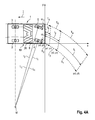
- the construction machine when reversing around a curve with reference to FIGS. 4B to 4C described, the construction machine is steered only with the rear wheels 4, 5.
- This steering mode means that the specification of certain steering angles specified by the operator acts only on the rear wheels, while the steering angle of the front wheels keeps the steering angle 0.
- the steering device 10 of the construction machine is designed such that it at least approximately backfills the Ackermann law.
- the extensions L 1 , L 2 , L 3 intersect all the wheel axles in the common center of curvature M. This assumes that the steering angle ⁇ 2 of the outside wheel is smaller than the steering angle ⁇ 1 of the inside wheel.
- the radius r of the circular arc on which a point of the construction machine moves is determined.
- the arithmetic unit 16 again calculates the start and end points of 6 trajectories T 1 to T 6 . Because the trajectories are not straight lines but Circular arcs between start and end points, the arithmetic unit calculates the radius r or the center M of the circular arcs, which results from the Ackermann law.
- Fig. 4A shows the trajectories T 1 to T 6 in the coordinate system (x, y) of the construction machine.
- the trajectories T 1 to T 6 are again converted into the coordinate system (x ', y') of the image recording unit 15, which Fig. 4B shows.
- the trajectories are corrected again with the first correction function in order to be able to take into account the distortion of the image recording unit ( Fig. 4C ).
- the viewing angle of the camera 12A of the image recording unit 15 changes simultaneously.
- the machine frame 6 when the front lifting columns 7 are raised and the rear lifting columns 8 are lowered, the machine frame 6 is raised in front and lowered at the rear. The machine frame thus tilts in the longitudinal direction. If, for example, the left lifting columns 7, 8 are raised and the right lifting columns 7, 8 are lowered, the machine frame is lifted on the left and lowered to the right. The machine frame 6 thus tilts transversely. Longitudinal and lateral inclinations can overlap. Since the camera 15A of the image recording unit 15 is fixedly connected to the machine frame 6, the camera follows the movements of the machine frame.
- a longitudinal and / or transverse inclination of the machine frame results in the trajectories displayed on the display unit 14 no longer matching the image of the rear area shown in the display unit, to which the trajectories are superimposed.
- the arithmetic unit 16 has means 16D for correcting the data describing the at least one trajectory in the coordinate system (x ', y') related to the image recording unit 15 on the basis of a second correction function, with which a change in pitch and / or bank angle and / or or height of the camera 12A of the image recording unit 15 with respect to the coordinate system (x, y) related to the chassis 1 of the construction machine. It is assumed that the trajectories have previously been calculated in the case where the machine frame 6 has a predetermined height with respect to the chassis 1 and is not inclined either longitudinally or laterally (reference plane).
- the backward image in the display unit "shortens".
- the path that the machine covers with one machine length remains the same. Therefore, the trajectories are stretched accordingly, which in extreme cases can cause the trajectories to run up out of the image, because the camera's viewing angle is so steep that an area at a distance of a machine length is no longer displayed.
- the picture lengthens because the camera looks far into the distance. Then the trajectories are compressed accordingly.
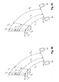
- FIGS. 5A to 5C show the case that the operator has selected the steering mode "coordinated steering" and has specified a certain steering angle. Since the steering device 10 of the construction machine approximately meets the Ackermann law, resulting from the specification of the steering angle, the corresponding positions of the wheels. The outside and inside wheels have different steering angle, the steering angle of the outside wheels are smaller than the steering angle of the inside wheels.
- the extensions L 1 , L 2 , L 3 , L 4 of the wheel axles intersect at the center of curvature M, whereby the radii r 1 , r 2 , r 3 , r 4 are given to the trajectories related to the individual wheel planes.
- the arithmetic unit 16 calculates the trajectories T 1 to T 6 , as described in the preceding embodiments, depending on the selected steering mode " coordinated steering" and the set steering angle, with which the movement of the construction machine is described ( Fig. 5A ).
- the trajectories T 1 , to T 6 in the coordinate system (x, y) of the construction machine ( Fig. 5A ) are converted back into the coordinate system (x ', y') of the image recording unit 15 ( Fig. 5B ) as described above. Again, a correction is made with the first and / or second correction function ( Fig. 5C ).
- FIGS. 6A to 6C show the steering mode "crab steering".
- the extensions of the wheel axles do not pass through a center of curvature, but all the axes are substantially parallel to each other.
- the trajectories point in the direction in which the wheels are pointing.
- the wheels on one side and the wheels on the other side are each directed in the same direction. However, they have different steering angles according to the Ackermann law.
- the steering angle ⁇ 2 of the front and rear wheels on one side is smaller than the steering angle ⁇ 1 of the front and rear wheels on the other side.
- the arithmetic unit 16 again calculates the trajectories T 1 to T 6 , which are determined by start and end point.
- the trajectories are in the steering mode "crab steering" not circular arcs, but straights.Since the wheels on one side have a different steering angle than the wheels on the other side to meet the Ackermann law, the directions on the The trajectories determined by the arithmetic unit have a direction lying between the two directions resulting from the different steering angles for the wheel on one side and the wheel on the other side.
- the trajectories T 1 to T 6 are again from the coordinate system (x, y) of the construction machine in the coordinate system (x ', y ') of the image recording unit ( Fig. 6B ). Again, a correction with the first and second correction function ( Fig. 6C ).
Landscapes
- Engineering & Computer Science (AREA)
- Civil Engineering (AREA)
- Structural Engineering (AREA)
- Mining & Mineral Resources (AREA)
- Mechanical Engineering (AREA)
- Architecture (AREA)
- Transportation (AREA)
- Combustion & Propulsion (AREA)
- Chemical & Material Sciences (AREA)
- General Engineering & Computer Science (AREA)
- Closed-Circuit Television Systems (AREA)
- Road Repair (AREA)
- Control Of Position, Course, Altitude, Or Attitude Of Moving Bodies (AREA)
- Steering Control In Accordance With Driving Conditions (AREA)
- Guiding Agricultural Machines (AREA)
- Operation Control Of Excavators (AREA)
Abstract
Description
Die Erfindung betrifft eine selbstfahrende Baumaschine, die über ein Fahrwerk mit in Arbeitsrichtung vorderen und hinteren Rädern oder Laufwerken verfügt, der von dem Fahrwerk getragen wird.The invention relates to a self-propelled construction machine, which has a chassis with front and rear wheels or drives in the working direction, which is supported by the chassis.
Die bekannten selbstfahrenden Baumaschinen, zu denen insbesondere die Straßenfräsmaschinen, Recycler oder Stabilisierer zählen, verfügen über eine Arbeitseinrichtung zum Durchführen der Baumaßnahme. Die Arbeitseinrichtung kann beispielsweise eine Fräseinrichtung, insbesondere eine Fräswalze sein.The known self-propelled construction machines, which include in particular the road milling machines, recyclers or stabilizers, have a working device for carrying out the construction measure. The working device may for example be a milling device, in particular a milling drum.
Derartige Baumaschinen unterscheiden sich von den Kraftfahrzeugen, insbesondere Personenkraftwagen (PKWs), dadurch, dass die Baumaschine sowohl mit den vorderen Rädern oder Laufwerken als auch mit den hinteren Rädern oder Laufwerken gelenkt werden kann. Dabei kann die Stellung, d. h. der Lenkeinschlag der vorderen bzw. hinteren Räder oder Laufwerke gegensinnig oder gleichsinnig sein. Wenn die vorderen Räder oder Laufwerke und die hinteren Räder oder Laufwerke in entgegengesetzte Richtungen gelenkt sind, kann die Baumaschine eine enge Kurve fahren, während die Baumaschine seitlich versetzend fahren kann, wenn die vorderen und hinteren Räder oder Laufwerke in die gleiche Richtung gelenkt sind.Such construction machines differ from motor vehicles, in particular passenger cars, in that the construction machine can be steered both with the front wheels or drives and with the rear wheels or drives. The position, d. H. the steering angle of the front or rear wheels or drives in opposite directions or in the same direction. If the front wheels or drives and the rear wheels or drives are steered in opposite directions, the construction machine can make a tight turn while the construction machine can travel laterally offset when the front and rear wheels or drives are steered in the same direction.
Die Vorgabe unterschiedlicher Lenkwinkel erlaubt dem Maschinenführer, die Baumaschine exakt im Gelände zu bewegen. Beim Zurücksetzen der Baumaschine stellt sich aber für den Maschinenführer das Problem, dass er den rückwärtigen Bereich der Baumaschine nur schwer einsehen kann. Während des normalen Arbeitseinsatzes wird die Baumaschine zwar nur in Vorwärtsrichtung betrieben, zum Verladen, Ansetzen oder Einparken muss der Maschinenführer die Baumaschine aber meist auf engem Raum zurücksetzen.The specification of different steering angles allows the machine operator to move the construction machine exactly off-road. When resetting the construction machine, however, the problem arises for the machine operator that it is difficult for him to see the rear area of the construction machine. Although the construction machine is operated only in the forward direction during normal work, the machine operator usually has to reset the construction machine in a confined space for loading, attachment or parking.
Der Maschinenführer soll sich beim Zurücksetzen von einer zweiten Person einweisen lassen. Dennoch ist das Zurücksetzen erschwert, da der Maschinenführer selbst den rückwärtigen Bereich nur bedingt einsehen kann. Es sind auch selbstfahrende Baumaschinen bekannt, die über eine Kamera an der Rückseite und einen Bildschirm auf dem Fahrstand verfügen. Zwar kann der Maschinenführer der Baumaschine dann den rückwärtigen Bereich einsehen, er kann aber auch mit einer Kamera nur schwer abschätzen, wie sich die Baumaschine beim Zurücksetzen bewegt.The machine operator should be instructed by a second person when resetting. Nevertheless, the reset is difficult because the operator even the rear area can see only limited. There are also self-propelled construction machines known, which have a camera on the back and a screen on the control station. Although the machine operator of the construction machine can then see the rear area, but it can also be difficult to estimate with a camera, as the construction machine moves when resetting.
Für Kraftfahrzeuge, insbesondere PKWs, sind Vorrichtungen bekannt, die den Fahrer beim Einparken des Fahrzeugs unterstützten. Derartige Vorrichtungen werden auch als Fahrerassistenzsysteme bezeichnet.For motor vehicles, especially cars, devices are known that assisted the driver when parking the vehicle. Such devices are also referred to as driver assistance systems.
Die
Die bekannten Fahrerassistenzsysteme für PKWs und LKWs sind nicht für selbstfahrende Baumaschinen geeignet, die sowohl mit den vorderen Rädern oder Laufwerken als auch mit den hinteren Rädern oder Laufwerken gelenkt werden können. Auch die Höhenverstellung mit einer Längs- und Querneigung des Maschinenrahmens stellt besondere Anforderungen an ein Fahrerassistenzsystem bei selbstfahrenden Baumaschinen.The known driver assistance systems for cars and trucks are not suitable for self-propelled construction machines that can be steered with both the front wheels or drives and with the rear wheels or drives. Also, the height adjustment with a longitudinal and transverse inclination of the machine frame makes special demands on a driver assistance system for self-propelled construction machines.
Der Erfindung liegt die Aufgabe zugrunde, eine selbstfahrende Baumaschine anzugeben, die dem Maschinenführer das Rückwärtsfahren, insbesondere zum Verladen, Ansetzen oder Einparken der Baumaschine, erleichtert.The invention has for its object to provide a self-propelled construction machine that facilitates the machine operator reversing, especially for loading, attaching or parking the construction machine.
Die Lösung dieser Aufgabe erfolgt erfindungsgemäß mit den Merkmalen des Patentanspruchs 1. Vorteilhafte Ausführungsformen der Erfindung sind Gegenstand der Unteransprüche.The solution of this object is achieved according to the invention with the features of
Die erfindungsgemäße selbstfahrende Baumaschine zeichnet sich durch eine Einrichtung zur Unterstützung des Maschinenführers beim Rückwärtsfahren aus, die eine Einheit zum Erfassen der Stellung der vorderen Räder oder Laufwerke und hinteren Räder oder Laufwerke und eine Recheneinheit zum Bestimmen von Daten aufweist, die mindestens eine Trajektorie der Baumaschine in Abhängigkeit von der Stellung der vorderen Räder oder Laufwerke und der hinteren Räder oder Laufwerke beschreiben. Darüber hinaus weist die Einrichtung zur Unterstützung des Maschinenführers beim Rückwärtsfahren eine Bildaufzeichnungseinheit zum Aufzeichnen eines Bildes des rückwärtigen Bereichs der Baumaschine und eine Anzeigeeinheit zur Darstellung des aufgezeichneten Bildes des rückwärtigen Bereichs der Baumaschine auf. Mit einer Bildverarbeitungseinheit wird dem auf der Anzeigeeinheit angezeigten Bild des rückwärtigen Bereichs der Baumaschine die Darstellung mindestens einer Trajektorie überlagert, mit der die Bewegung der Baumaschine im Gelände oder auf Verkehrswegen oder- flächen beschrieben wird.The self-propelled construction machine according to the invention is characterized by a device for assisting the operator when reversing, comprising a unit for detecting the position of the front wheels or drives and rear wheels or drives and a computing unit for determining data, the at least one trajectory of the construction machine in Depend on the position of the front wheels or drives and the rear wheels or drives. In addition, when reversing, the device for assisting the machine operator has an image recording unit for recording an image of the rear area of the construction machine and a display unit for displaying the recorded image of the rear area of the construction machine. An image processing unit superimposes on the image of the rear area of the construction machine displayed on the display unit the representation of at least one trajectory with which the movement of the construction machine in the field or on traffic routes or areas is described.
Die Einrichtung zur Unterstützung des Maschinenführers beim Rückwärtsfahren berücksichtigt sowohl die Stellung der vorderen als auch hinteren Räder oder Laufwerke. Es können eine oder mehrere Trajektorien bestimmt werden, die dem Bild des rückwärtigen Bereichs der Baumaschine überlagert werden. Anhand der mindestens einen Trajektorie kann der Maschinenführer beim Rückwärtsfahren genau abschätzen, wie sich die Baumaschine in Abhängigkeit von der Stellung sowohl der vorderen als auch hinteren Räder bzw. Laufwerke um ggf. vorhandene Hindernisse bewegt.The device for assisting the operator when reversing considers both the position of the front and rear wheels or drives. One or more trajectories may be determined superimposed on the image of the rear of the construction machine. On the basis of the at least one trajectory, the operator can accurately estimate when reversing how the construction machine moves depending on the position of both the front and rear wheels or drives to possibly existing obstacles.
Bei einer bevorzugten Ausführungsform verfügt die Bedieneinheit der Baumaschine sowohl über Mittel zum Vorgeben eines Lenkwinkels für die vorderen und/oder hinteren Räder oder Laufwerke als auch über Mittel zur Auswahl eines Lenkmodus aus einer Mehrzahl von Lenkmodi. Dabei wirkt die Bedieneinheit der Baumaschine derart mit der Lenkeinrichtung der Maschine zusammen, dass die Lenkeinrichtung den vorgegebenen Lenkwinkel bzw. den ausgewählten Lenkmodus einstellt. Die Recheneinheit der Einrichtung zur Unterstützung des Maschinenführers beim Rückwärtsfahren, mit der die Daten bestimmt werden, die mindestens eine Trajektorie der Baumaschine in Abhängigkeit von der Stellung der vorderen und hinteren Räder oder Laufwerke beschreiben, weist bei der bevorzugten Ausführungsform Mittel zum Berechnen von den die mindestens eine Trajektorie beschreibenden Daten nicht nur in Abhängigkeit von der Stellung der vorderen und/oder hinteren Räder oder Laufwerke, sondern auch in Abhängigkeit von dem ausgewählten Lenkmodus auf.In a preferred embodiment, the operating unit of the construction machine has both means for prescribing a steering angle for the front and / or rear wheels or drives as well as means for selecting a steering mode from a plurality of steering modes. In this case, the operating unit of the construction machine interacts with the steering device of the machine such that the steering device sets the predetermined steering angle or the selected steering mode. The arithmetic unit of the device for assisting the machine operator in reversing, which determines the data describing at least one trajectory of the construction machine in dependence on the position of the front and rear wheels or drives, has in the preferred embodiment means for calculating at least the a Trajectory descriptive data not only in dependence on the position of the front and / or rear wheels or drives, but also in dependence on the selected steering mode.
Bei der bevorzugten Ausführungsform kann der Maschinenführer sofort nach Vorgabe von Lenkwinkel und Lenkmodus erkennen, wie sich die Maschine beim Rückwärtsfahren verhält. Durch Verändern des Lenkwinkels einerseits und des Lenkmodus andererseits kann der Maschinenführer abschätzen, welche Auswirkungen unterschiedliche Lenkwinkel bzw. Lenkmodi haben. Dadurch ist es dem Maschinenführer möglich, beim Rückwärtsfahren nicht nur die Bewegung der Maschine besser abzuschätzen, sondern auch den optimalen Lenkwinkel bei optimalem Lenkmodus oder umgekehrt vorzugeben.In the preferred embodiment, the operator, as dictated by the steering angle and steering mode, can immediately recognize how the engine behaves when reversing. By varying the steering angle on the one hand and the steering mode on the other hand, the operator can estimate what effects have different steering angles or steering modes. This makes it possible for the operator to not only better estimate the movement of the machine when reversing, but also to specify the optimum steering angle in optimum steering mode or vice versa.
Die Mittel zum Berechnen von den die mindestens eine Trajektorie beschreibenden Daten sind bei einer besonders bevorzugten Ausführungsform derart ausgebildet, dass die Daten die Trajektorie bei dem ausgewählten Lenkmodus und dem vorgegebenen Lenkwinkel in einem auf das Fahrwerk der Baumaschine bezogenen Koordinatensystem beschreiben. Dieses Koordinatensystem ist vorzugsweise ein Koordinatensystem, das sich nicht verändert, wenn der Maschinenrahmen gegenüber dem Fahrwerk mit einer vorgegebenen Quer- und/oder Längsneigung in der Höhe verstellt wird.The means for calculating the data describing the at least one trajectory are formed in a particularly preferred embodiment such that the data describe the trajectory in the selected steering mode and the predetermined steering angle in a coordinate system related to the chassis of the construction machine. This coordinate system is preferably a coordinate system that does not change when the machine frame is adjusted in height with respect to the chassis with a predetermined lateral and / or longitudinal inclination.
Eine bevorzugte Ausführungsform der erfindungsgemäßen Baumaschine geht davon aus, dass die Lenkung der Baumaschine im Wesentlichen dem Ackermann-Gesetz genügt, so dass sich die Verlängerung der Achsen der Räder oder Laufwerke in einem Kurvenmittelpunkt schneiden. Wenn die Baumaschine gegensinnig gelenkt wird, lassen sich die Trajektorien durch Kreisbögen darstellen, die sich durch Start- und Endpunkt sowie einen Kurvenmittelpunkt und/oder Radius beschreiben lassen. Wenn die mindestens eine Trajektorie eine Gerade ist, was bei einer gleichsinnigen Lenkung der Fall ist, kann die Trajektorie allein durch den Start- und Endpunkt beschrieben werden. Es ist aber grundsätzlich auch möglich, die Trajektorie anders zu beschreiben, beispielsweise durch die Koordinaten einer Vielzahl von Punkten im Koordinatensystem.A preferred embodiment of the construction machine according to the invention assumes that the steering of the construction machine essentially satisfies the Ackermann law, so that the extension of the axes of the wheels or drives intersect at a curve center. If the construction machine is steered in opposite directions, the trajectories can be represented by circular arcs, which can be described by start and end point as well as a curve center and / or radius. If the at least one trajectory is a straight line, which is the case with a steering in the same direction, the trajectory can be described solely by the start and end points. However, it is also possible in principle to describe the trajectory differently, for example by the coordinates of a plurality of points in the coordinate system.
Die Recheneinheit weist vorzugsweise Mittel zum Umrechnen der die mindestens eine Trajektorie beschreibenden Daten in ein auf die Bildaufzeichnungseinheit bezogenes Koordinatensystem auf, in dem das Bild auf der Anzeigeeinheit dargestellt wird. Damit ist es möglich, für die Bildaufzeichnungseinheit ein anderes Koordinatensystem zu wählen, als das Koordinatensystem der Baumaschine. Folglich kann die Bildaufzeichnungseinheit an der Baumaschine beliebig angeordnet werden, um dem Maschinenführer ein Bild unter einem bestimmten Blickwinkel zeigen zu können.The arithmetic unit preferably has means for converting the data describing the at least one trajectory into a coordinate system related to the image recording unit, in which the image is displayed on the display unit. This makes it possible to select a different coordinate system for the image recording unit than the coordinate system of the construction machine. Consequently, the image recording unit can be arbitrarily arranged on the construction machine so as to be able to show the operator an image from a certain viewpoint.
Bei einer bevorzugten Ausführungsform der erfindungsgemäßen Baumaschine ist der Maschinenrahmen in der Höhe und/oder Neigung verstellbar ausgebildet. Von Vorteil ist, wenn die korrekte Darstellung der mindestens einen Trajektorie in dem auf der Anzeigeeinheit angezeigten Bild des rückwärtigen Bereichs unabhängig von Höhe und/oder Neigung des Maschinenrahmens erfolgt. Daher weist die Recheneinheit bei einer weiteren besonders bevorzugten Ausführungsform Mittel zum Korrigieren der die mindestens eine Trajektorie beschreibenden Daten in dem auf die Bildaufzeichnungseinheit bezogenen Koordinatensystem auf der Grundlage einer Korrekturfunktion auf, mit der eine Veränderung der Längsneigung und/oder Querneigung und/oder Höhe der Bildaufzeichnungseinheit in Bezug auf das auf das Fahrwerk der Baumaschine bezogene Koordinatensystem berücksichtigt wird.In a preferred embodiment of the construction machine according to the invention, the machine frame is adjustable in height and / or inclination. It is advantageous if the correct representation of the at least one trajectory in the image of the rear area displayed on the display unit takes place independently of the height and / or inclination of the machine frame. Therefore, in another particularly preferred embodiment, the arithmetic unit comprises means for correcting the data describing the at least one trajectory in the coordinate system related to the image recording unit based on a correction function including a change in the pitch and / or bank angle and / or height of the image recording unit is taken into account with respect to the coordinate system related to the chassis of the construction machine.
Eine Veränderung der Höhe und/oder Neigung des Maschinenrahmens gegenüber dem sich auf das Fahrwerk der Baumaschine bezogene Koordinatensystem führt auch zu einer Veränderung der Höhe und/oder Neigung der am Maschinenrahmen angeordneten Bildaufzeichnungseinheit. Die Mittel zum Korrigieren der die mindestens eine Trajektorie beschreibenden Daten stellen sicher, dass eine Veränderung der Höhe und/oder Neigung des Maschinenrahmens gegenüber dem sich auf das Fahrwerk der Baumaschine bezogene Koordinatensystem nicht zu einer falschen Anzeige der mindestens einen Trajektorie auf der Anzeigeeinheit führt. Die die mindestens eine Trajektorie beschreibenden Daten werden also in Abhängigkeit von der Höhe und/oder Neigung des Maschinenrahmens so transformiert, dass sie wieder zu dem Bild des rückwärtigen Bereichs passen, dass auf der Anzeigeinheit angezeigt wird.A change in the height and / or inclination of the machine frame relative to the coordinate system relative to the chassis of the construction machine also leads to a change in the height and / or inclination of the image recording unit arranged on the machine frame. The means for correcting the data describing the at least one trajectory ensure that a change in the height and / or inclination of the machine frame relative to the coordinate system related to the chassis of the construction machine does not lead to a false display of the at least one trajectory on the display unit. The data describing the at least one trajectory are thus transformed depending on the height and / or inclination of the machine frame so that they again match the image of the rear area that is displayed on the display unit.
Da die Objektive der bekannten Kameras insbesondere in den Randbereichen verzerren, können Ungenauigkeiten bei der Darstellung der Trajektorie in Bezug auf die Darstellung des Bildes des rückwärtigen Bereichs der Baumaschine auftreten. Daher sieht eine besonders bevorzugte Ausführungsform Mittel zum Korrigieren der die mindestens eine Trajektorie beschreibenden Daten in dem auf die Bildaufzeichnungseinheit bezogenen Koordinatensystem auf der Grundlage einer Korrekturfunktion vor, mit der eine Verzerrung des mit der Bildaufzeichnungseinheit aufgezeichneten Bildes berücksichtigt wird. Bei dieser besonders bevorzugten Ausführungsform wird die mindestens eine Trajektorie so verzerrt wie das Bild des rückwärtigen Bereichs verzerrt wird. Diese besonders bevorzugte Ausführungsform kommt mit einer relativ geringen Rechenleistung aus, da nicht das Bild entzerrt zu werden braucht, sondern nur die Trajektorie verzerrt wird, um beide Darstellungen auf der Anzeigeeinheit in korrekter Beziehung zueinander zu zeigen. Es ist aber auch möglich, dass die Recheneinheit Mittel zum Korrigieren des Bildes des rückwärtigen Bereichs der Baumaschine in dem auf die Bildaufzeichnungseinheit bezogenen Koordinatensystem auf der Grundlage einer Korrekturfunktion aufweist, mit der Verzerrung des mit der Bildaufzeichnungseinheit aufgezeichneten Bilds korrigiert wird. Hierzu ist allerdings eine höhere Rechenleistung erforderlich.Since the lenses of the known cameras distort in particular in the edge regions, inaccuracies in the representation of the trajectory with respect to the representation of the image of the rear area of the construction machine can occur. Therefore, a particularly preferred embodiment provides means for correcting the data describing the at least one trajectory in the coordinate system related to the image recording unit on the basis of a correction function taking into account distortion of the image recorded by the image recording unit. In this particularly preferred embodiment, the at least one trajectory is distorted as the image of the rear region is distorted. This particularly preferred embodiment has a relatively low computational power because it does not need to equalize the image, but only distorts the trajectory to show both representations on the display unit in correct relationship. However, it is also possible that the arithmetic unit has means for correcting the image of the rear area of the construction machine in the coordinate system related to the image recording unit on the basis of a correction function with which distortion of the image recorded by the image recording unit is corrected. For this purpose, however, a higher computing power is required.
Eine Trajektorie ist eine Bahn, die ein beliebiger Punkt beschreibt. Dieser Punkt kann auf der Baumaschine liegen, um genau einen Punkt der Maschine zu kennzeichnen, oder auch neben der Maschine liegen, um einen Sicherheitsabstand zu einem auf der Maschine liegenden Punkt zu kennzeichnen. Die Daten, mit denen die mindestens eine Trajektorie beschrieben werden, können unterschiedliche Daten sein. Beispielsweise kann die Trajektorie durch einen Start- und Endpunkt sowie einen Kreismittelpunkt oder einen Radius beschrieben werden. Die Wegstrecke zwischen Start- und Endpunkt kann die Fahrzeuglänge oder ein Teil der Fahrzeuglänge sein. Vorzugsweise werden mehrere Trajektorien angezeigt, wobei eine der Trajektorien die Fahrzeuglänge darstellt und die anderen Trajektorien Teile der Fahrzeuglänge darstellen.A trajectory is a trajectory that describes any point. This point can be on the construction machine to mark exactly one point of the machine, or even next to the machine to mark a safe distance from a point on the machine. The data describing the at least one trajectory may be different data. For example, the trajectory can be described by a start and end point as well as a circle center or a radius. The distance between start and end point may be the vehicle length or part of the vehicle length. Preferably, a plurality of trajectories are displayed, wherein one of the trajectories represents the vehicle length and the other trajectories represent parts of the vehicle length.
Wenn die Trajektorien genau der Fahrzeuglänge oder Teilen der Fahrzeuglänge entsprechen, sollte der Punkt am äußersten Ende des Hecks der Maschine liegen, um dem Maschinenführer beim Rückwärtsfahren die Position des Hecks anzuzeigen. Mit einer Trajektorie kann beispielsweise auch die Bewegung eines Punktes auf der Arbeitseinrichtung der Maschine, beispielsweise der Fräseinrichtung, visualisiert werden.If the trajectories correspond exactly to the vehicle length or parts of the vehicle length, the point should be at the extreme end of the rear of the machine to accommodate the When reversing, the operator should indicate the position of the stern. With a trajectory, for example, the movement of a point on the working device of the machine, for example the milling device, can be visualized.
Die Trajektorien können nicht nur als Linien zwischen Start- und Endpunkten, sondern auch als Punktwolken dargestellt werden, um die Bewegung der Baumaschine auf der Anzeigeeinheit zu visualisieren.The trajectories can be displayed not only as lines between start and end points, but also as point clouds to visualize the movement of the construction machine on the display unit.
Nachfolgend wird ein Ausführungsbeispiel der Erfindung unter Bezugnahme auf die Zeichnungen näher erläutert.Hereinafter, an embodiment of the invention will be explained in more detail with reference to the drawings.
Es zeigen:
- Fig. 1
- eine Straßenfräsmaschine als ein Beispiel für eine selbstfahrende Baumaschine in der Seitenansicht,
- Fig. 2
- ein Blockschaltbild einer Einrichtung zur Unterstützung des Maschinenführers beim Rückwärtsfahren,
- Fig. 3A
- die selbstfahrende Baumaschine in stark vereinfachter schematischer Darstellung und eine Darstellung der Trajektorien in einem auf die Baumaschine bezogenen Koordinatensystem, wobei die Baumaschine geradeaus rückwärts fährt,
- Fig. 3B
- die Trajektorien der Baumaschine von
Fig. 3A in einem auf die Bildaufzeichnungseinheit bezogenen Koordinatensystem, - Fig. 3C
- die Trajektorien von
Fig. 3B nach der Korrektur zur Berücksichtigung der Verzerrung der Bildaufzeichnungseinheit, - Fig. 4A
- die Baumaschine in stark vereinfachter schematischer Darstellung und eine Darstellung der Trajektorien in dem auf die Baumaschine bezogenen Koordinatensystem, wobei die Baumaschine in einem Lenkmodus rückwärts fährt, bei dem die Baumaschine nur mit den Hinterrädern gelenkt wird,
- Fig. 4B
- die Trajektorien von
Fig. 4A in dem auf die Bildaufzeichnungseinheit bezogenen Koordinatensystem, - Fig. 4C
- die Trajektorien von
Fig. 4B nach der Korrektur zur Berücksichtigung der Verzerrung der Bildaufzeichnungseinheit, - Fig.5A
- die Baumaschine in stark vereinfachter schematischer Darstellung und eine Darstellung der Trajektorien in dem auf die Baumaschine bezogenen Koordinatensystem, wobei die Baumaschine in einem Lenkmodus rückwärts fährt, bei dem Vorder- und Hinterräder gegensinnig lenken,
- Fig. 5B
- die Trajektorien von
Fig. 5A in dem auf die Bildaufzeichnungseinheit bezogenen Koordinatensystem, - Fig. 5C
- die Trajektorien von
Fig. 5B nach der Korrektur zur Berücksichtigung der Verzerrung der Bildaufzeichnungseinheit, - Fig. 6A
- die Baumaschine in stark vereinfachter schematischer Darstellung und eine Darstellung der Trajektorien in dem auf die Baumaschine bezogenen Koordinatensystem, wobei die Baumaschine in einem Lenkmodus rückwärts fährt, bei dem Vorder- und Hinterräder gleichsinnig lenken,
- Fig. 6B
- die Trajektorien von
Fig. 6A in dem auf die Bildaufzeichnungseinheit bezogenen Koordinatensystem und - Fig. 6C
- die Trajektorien von
Fig. 6B nach der Korrektur zur Berücksichtigung der Verzerrung der Bildaufzeichnungseinheit.
- Fig. 1
- a road milling machine as an example of a self-propelled construction machine in side view,
- Fig. 2
- a block diagram of a device for assisting the machine operator when reversing,
- Fig. 3A
- the self-propelled construction machine in a highly simplified schematic representation and a representation of the trajectories in a related to the construction machine coordinate system, the construction machine goes straight backward,
- Fig. 3B
- the trajectories of the construction machine of
Fig. 3A in a coordinate system related to the image recording unit, - Fig. 3C
- the trajectories of
Fig. 3B after the correction for taking into account the distortion of the image recording unit, - Fig. 4A
- the construction machine in a highly simplified schematic representation and a representation of the trajectories in the related to the construction machine Coordinate system, wherein the construction machine reverses in a steering mode in which the construction machine is steered only with the rear wheels,
- Fig. 4B
- the trajectories of
Fig. 4A in the coordinate system related to the image recording unit, - Fig. 4C
- the trajectories of
Fig. 4B after the correction for taking into account the distortion of the image recording unit, - 5A
- the construction machine in a highly simplified schematic representation and a representation of the trajectories in the related to the construction machine coordinate system, the construction machine in a steering mode backwards, steering in the front and rear wheels in opposite directions,
- Fig. 5B
- the trajectories of
Fig. 5A in the coordinate system related to the image recording unit, - Fig. 5C
- the trajectories of
Fig. 5B after the correction for taking into account the distortion of the image recording unit, - Fig. 6A
- the construction machine in a highly simplified schematic representation and a representation of the trajectories in the related to the construction machine coordinate system, the construction machine in a steering mode backwards, steer in the same direction in the front and rear wheels,
- Fig. 6B
- the trajectories of
Fig. 6A in the coordinate system related to the image recording unit and - Fig. 6C
- the trajectories of
Fig. 6B after the correction for taking into account the distortion of the image recording unit.
Bei der Straßenfräsmaschine handelt es sich um eine sogenannte Großfräse zum Abfräsen von Straßenbelägen. Die Baumaschine weist ein Fahrwerk 1 auf, das in Arbeitsrichtung I zwei vordere Laufwerke 2, 3 und zwei hintere Laufwerke 4,5 aufweist. Anstelle von vorderen und hinteren Laufwerken kann das Fahrwerk auch vordere und hintere Räder aufweisen. Nachfolgend werden die Laufwerke einfach als Räder bezeichnet.The road milling machine is a so-called large milling machine for milling road surfaces. The construction machine has a
Das Fahrwerk 1 trägt einen Maschinenrahmen 6, der mittels zwei vorderen und zwei hinteren Hubsäulen 7, 8 in Bezug auf das Gelände oder den Verkehrsweg oder die Verkehrsfläche in der Höhe verstellbar ist, wobei auch die Längs- und/oder Querneigung des Maschinenrahmens 6 verstellbar ist.The
Die Baumaschine verfügt über eine nicht dargestellte Messeinrichtung, mit der die Stellung des Maschinenrahmens in Bezug auf eine Bezugsebene, d. h. die Höhe und Neigung des Maschinenrahmens bezüglich der Bezugsebene, erfasst wird. Eine derartige Messeinrichtung ist in der
Darüber hinaus verfügt die Baumaschine über eine nicht näher dargestellte Antriebseinrichtung 9 zum Antreiben der Vorder- und Hinterräder 2, 3; 4, 5 und eine Lenkeinrichtung 10 zum Lenken der Vorder- und Hinterräder 2, 3; 4, 5 sowie eine Fräseinrichtung 19 mit einer Fräswalze 20, die zwischen den Vorder- und Hinterrädern angeordnet ist.In addition, the construction machine has a non-illustrated drive means 9 for driving the front and
Am Maschinenrahmen 6 ist zwischen Vorder- und Hinterrädern 2, 3; 4, 5 der Fahrstand 11 der Baumaschine angeordnet. Der Fahrerstand kann selbstverständlich auch an einer anderen Stelle angeordnet sein, so z. B. vor den Vorderrädern. An dem Fahrstand 11 befindet sich eine nur andeutungsweise dargestellte Bedieneinheit 12 für die Baumaschine.On the
Die Bedieneinheit 12 weist Mittel 12A zum Vorgeben eines bestimmten Lenkwinkels für die Vorder- und Hinterräder 2, 3 und Mittel 12B zur Auswahl eines bestimmten Lenkmodus auf. Bei den Mitteln 12A zum Vorgeben des Lenkwinkels kann es sich um ein Lenkrad 12A handeln, während es sich bei den Mitteln zur Auswahl des Lenkmodus um einen Wahlhebel 12B handeln kann. Lenkrad 12A und Wahlhebel 12B sind in
Der Maschinenführer kann aus einer Mehrzahl von Lenkmodi mit dem Wahlhebel 12B einen bestimmten Lenkmodus auswählen. Bei einem als "coordinated steering" bezeichneten Lenkmodus wird die Baumaschine mit Vorder- und Hinterrädern 2, 3; 4, 5 gegensinnig gelenkt, wobei die Vorderräder 2 und die Hinterräder 3 in entgegengesetzte Richtungen zeigen. Der Maschinenführer wählt diesen Lenkmodus, wenn er einen engen Radius fahren will. Bei einem als ,,crab steering" bezeichneten Lenkmodus wird die Baumaschine mit den Vorder- und Hinterrädern 2, 3; 4, 5 gleichsinnig gelenkt, wobei die Vorderräder 2, 3 und die Hinterräder 4, 5 in die gleiche Richtung zeigen. Dieser Lenkmodus wird gewählt, wenn die Baumaschine seitlich versetzend fahren soll. Die Baumaschine kann aber auch nur mit den Vorderrädern oder nur mit den Hinterrädern gelenkt werden.The operator may select a particular steering mode from a plurality of steering modes with the
Für sämtliche Lenkmodi gilt, dass der Maschinenführer die Baumaschine nur mit dem Lenkrad 12A lenkt. Dabei werden in Abhängigkeit des Lenkmodus nur die Hinterräder, nur die Vorderräder oder sowohl die Vorder- als auch Hinterräder gelenkt, wobei dann die Vorder- und Hinterräder entweder gleichsinnig oder gegensinnig gelenkt werden. Die sich einstellenden Lenkwinkel an den Vorder- und Hinterachsen sind durch die Geometrie der Lenkeinrichtung vorgegeben, was nachfolgend noch erläutert wird.For all steering modes, the operator only steers the construction machine with the
Das Bild des rückwärtigen Bereichs der Baumaschine wird mit einer Bildaufzeichnungseinheit 15 aufgezeichnet, die eine am rückwärtigen Bereich des Maschinenrahmens angeordnete Kamera 15A aufweist. Die Kamera 15A folgt in Bezug auf Höhe und Neigung gegenüber dem Gelände den Bewegungen des Maschinenrahmens 6 der Baumaschine. Vorzugsweise befindet sich die Kamera 15A am Heck der Maschine.The image of the rear portion of the construction machine is recorded with an
Die Einrichtung 13 zur Unterstützung beim Rückwärtsfahren weist eine Recheneinheit 16 auf, mit der die Daten bestimmt werden, die mindestens eine Trajektorie der Baumaschine in Abhängigkeit von der Stellung der Vorder- und Hinterräder und in Abhängigkeit von dem Lenkmodus beschreiben. Die Stellung der Vorder- und Hinterräder wird mit einer Einheit 17 erfasst, die Teil der Einrichtung 13 zur Unterstützung beim Rückwärtsfahren oder Teil der Lenkeinrichtung 10 sein kann. Das Blockschaltbild von
Darüber hinaus weist die Einrichtung 13 zur Unterstützung des Maschinenführers eine Bildverarbeitungseinheit 18 auf, die dem auf der Anzeigeeinheit 14 angezeigten Bild des rückwärtigen Bereichs der Baumaschine die mindestens eine Trajektorie überlagert, die von der Recheneinheit 16 bestimmt wird. Folglich sieht der Maschinenführer sowohl die mindestens eine Trajektorie als auch den rückwärtigen Bereich der Baumaschine auf der Anzeigeeinheit, so dass der Maschinenführer die Bewegung der Baumaschine den Objekten zuordnen kann, die sich im Gelände oder auf dem Verkehrsweg befinden. Über die mindestens eine Trajektorie hinaus können auch weitere Informationen dargestellt werden, wie z. B. die Entfernungen.In addition, the
Nachfolgend wird Aufbau und Funktionsweise der einzelnen Komponenten der Einrichtung 13 zur Unterstützung des Maschinenführers beim Rückwärtsfahren für die einzelnen Lenkmodi näher erläutert.The structure and mode of operation of the individual components of the
Die
Der Maschinenrahmen 6 der Baumaschine ist in dem Koordinatensystem durch ein Rechteck dargestellt. Die Eckpunkte des Rechtecks entsprechen den vorderen und hinteren Eckpunkten der Maschine. Zwischen den Vorder- und Hinterrädern 2, 3; 4, 5 befindet sich die Fräseinrichtung 19 mit der Fräswalze 20.The
Der Nullpunkt (x0, y0) in dem auf das Fahrwerk der Maschine bezogenen Koordinatensystems liegt auf dem hinteren in Arbeitsrichtung I linken Eckpunkt des Maschinenrahmen 6.The zero point (x0, y0) in the coordinate system related to the chassis of the machine lies on the rear left in the working direction I corner of the machine frame. 6
Die Recheneinheit 16 verfügt über Mittel 16A, die für die Darstellung der Rückwärtsbewegung der Baumaschine bei dem vorliegenden Ausführungsbeispiel insgesamt sechs Trajektorien berechnen, die jeweils durch einen Startpunkt und einen Endpunkt beschrieben werden. Da die Baumaschine geradeaus rückwärts fährt, sind die Trajektorien Geraden zwischen den beiden Punkten.The
Zur Bestimmung der Trajektorie des in Arbeitsrichtung I hinteren linken Eckpunkts (x0, y0) der Baumaschine beim Rückwärtsfahren um einen vorgegebenen Weg, der der Länge des Maschinenrahmens entspricht, berechnet die Recheneinheit die Koordinaten (x3, y3) des Punkts in dem auf das Fahrwerk der Baumaschine bezogenen Koordinatensystem, an dem sich der hintere linke Eckpunkt des Maschinenrahmens befindet, wenn die Baumaschine um die Fahrzeuglänge (l1), beispielsweise 9 m zurückgesetzt hat. Entsprechend berechnet die Recheneinheit die Koordinaten (x2, y2) bzw. (x1, y1), an dem sich der hintere linke Eckpunkt (x0, y0) der Baumaschine befindet, wenn die Baumaschine um eine kürzere Wegstrecke (l2 bzw. l3), beispielsweise 3 m bzw. 1 m, zurückgesetzt hat. Diese Berechnungen erfolgen auch für den in Arbeitsrichtung I rechten hinteren Eckpunkt des Maschinenrahmens. Daraus ergibt sich eine Darstellung von 6 Trajektorien T1 bis T6, die durch Pfeile gekennzeichnet sind. Die gestrichelten Verbindungslinien zwischen den Spitzen der Pfeile kennzeichnen die Position des Hecks der Baumaschine beim Zurücksetzen um die jeweilige Wegstrecke, beispielsweise 9 m, 3 m, 1 m.In order to determine the trajectory of the rear left vertex (x0, y0) of the construction machine when reversing by a predetermined distance that corresponds to the length of the machine frame, the arithmetic unit calculates the coordinates (x3, y3) of the point in the vehicle Construction machine related coordinate system, where the rear left corner point of the machine frame is when the construction machine has reset by the vehicle length (l 1 ), for example 9 m. Accordingly, the arithmetic unit calculates the coordinates (x2, y2) or (x1, y1) at which the rear left vertex (x0, y0) of the construction machine is located when the construction machine by a shorter distance (l 2 or l 3 ) , For example, 3 m and 1 m, has reset. These calculations are also made for the right in the working direction I rear corner of the machine frame. This results in a representation of 6 trajectories T 1 to T 6 , which are indicated by arrows. The dashed connecting lines between the tips of the arrows indicate the position of the rear of the construction machine when resetting by the respective distance, for example, 9 m, 3 m, 1 m.
Die in
Das vorliegende Ausführungsbeispiel berücksichtigt auch mögliche Verzerrungen, die bei der Aufzeichnung des Bildes der Bildaufzeichnungseinheit auftreten können. Beispielsweise verzerrt das Objektiv der Kamera 15A insbesondere im Randbereich. Derartige Verzerrungen können dazu führen, dass die Objekte im Gelände oder auf den Verkehrswegen oder- flächen, die auf der Anzeigeeinheit dargestellt werden, nicht exakt den Trajektorien zugeordnet sind, die dem Bild des rückwärtigen Bereichs der Baumaschine überlagert sind.The present embodiment also takes into account possible distortions that may occur when recording the image of the image recording unit. For example, the lens of the
Die Recheneinheit 16 weist Mittel 16C zum Korrigieren der die Trajektorien T1, bis T6 beschreibenden Daten (x0', y0') bis (x3', y3') in dem auf die Bildaufzeichnungseinheit bezogenen Koordinatensystem (x', y') auf. Die Mittel 16C korrigieren die Daten auf der Grundlage einer ersten Korrekturfunktion. Mit der ersten Korrekturfunktion werden die Daten so korrigiert, dass die Darstellung der Trajektorien T1, bis T6 im Wesentlichen derselben Verzerrung unterliegen wie das von der Kamera 15A aufgenommene Bild.
Auf der Anzeigeeinheit 14 (
Nachfolgend wird die Bewegung der Baumaschine beim Rückwärtsfahren um eine Kurve unter Bezugnahme auf die
Die Lenkeinrichtung 10 der Baumaschine ist derart ausgebildet, dass sie zumindest näherungsweise das Ackermann-Gesetz verfüllt. Nach dem Ackermann-Gesetz schneiden sich die Verlängerungen L1, L2, L3 aller Radachsen im gemeinsamen Kurvenmittelpunkt M. Dies setzt voraus, dass der Lenkwinkel α2 des kurvenäußeren Rades kleiner als der Lenkwinkel α1 des kurveninneren Rades ist. Mit dem Ackermann-Gesetz ist der Radius r des Kreisbogens bestimmt, auf dem sich ein Punkt der Baumaschine bewegt. Wie bei dem ersten Ausführungsbeispiel berechnet die Recheneinheit 16 wieder die Start- und Endpunkte von 6 Trajektorien T1 bis T6. Da die Trajektorien nicht Geraden, sondern Kreisbögen zwischen Start- und Endpunkten sind, berechnet die Recheneinheit den Radius r oder den Mittelpunkt M der Kreisbögen, der sich aus dem Ackermann-Gesetz ergibt.The
Wenn der Maschinenrahmen 6 der Baumaschine in der Höhe verstellt wird, wobei sich auch Quer- und/oder Längsneigung des Maschinenrahmens ändern können, ändert sich gleichzeitig der Blickwinkel der Kamera 12A der Bildaufzeichnungseinheit 15.When the
Wenn beispielsweise die vorderen Hubsäulen 7 hochgefahren und die hinteren Hubsäulen 8 runtergefahren werden, wird der Maschinenrahmen 6 vorne angehoben und hinten abgesenkt. Der Maschinenrahmen neigt sich folglich in Längsrichtung. Wenn beispielsweise die linken Hubsäulen 7, 8 hochgefahren und die rechten Hubsäulen 7, 8 runtergefahren werden, wird der Maschinenrahmen links angehoben und rechts abgesenkt. Der Maschinenrahmen 6 neigt sich folglich in Querrichtung. Längs- und Querneigung können sich auch überlagern. Da die Kamera 15A der Bildaufzeichnungseinheit 15 fest mit dem Maschinenrahmen 6 verbunden ist, folgt die Kamera den Bewegungen des Maschinenrahmens.For example, when the
Eine Längs- und/oder Querneigung des Maschinenrahmens führt dazu, dass die auf der Anzeigeeinheit 14 dargestellten Trakjektorien nicht mehr zu dem in der Anzeigeeinheit dargestellten Bild des rückwärtigen Bereichs passen, dem die Trajektorien überlagert sind.A longitudinal and / or transverse inclination of the machine frame results in the trajectories displayed on the
Die Recheneinheit 16 weist Mittel 16D zum Korrigieren der die mindestens eine Trajektorie beschreibenden Daten in dem auf die Bildaufzeichnungseinheit 15 bezogenen Koordinatensystem (x', y') auf der Grundlage einer zweiten Korrekturfunktion auf, mit der eine Veränderung der Längsneigung und/oder Querneigung und/oder Höhe der Kamera 12A der Bildaufzeichnungseinheit 15 in Bezug auf das auf das Fahrwerk 1 der Baumaschine bezogene Koordinatensystem (x, y) berücksichtigt wird. Dabei wird davon ausgegangen, dass die Trajektorien zuvor für den Fall berechnet worden sind, dass der Maschinenrahmen 6 in Bezug auf das Fahrwerk 1 eine vorgegebene Höhe hat und weder in Längs- noch in Querrichtung geneigt ist (Bezugsebene). Bei einer Veränderung der Höhe und/oder Neigung des Maschinenrahmen 6 werden die auf der Anzeigeeinheit 14 dargestellten Trajektorien mit der zweiten Korrekturfunktion in Abhängigkeit von der Höhe und/oder Neigung, die mit der nicht dargestellten Messeinrichtung erfasst wird, so transformiert, dass das auf der Anzeigeeinheit dargestellte Bild, beispielsweise die Objekte O1 und 02, und die Trajektorien wieder in dem richtigen Verhältnis zueinander dargestellt werden.The
Wenn beispielsweise der Maschinenrahmen 6 vorne hochgefahren und hinten runtergefahren wird, dann "verkürzt" sich das rückwärtig Bild in der Anzeigeeinheit. Der Weg, den die Maschine mit einer Maschinenlänge zurücklegt, bleibt aber der gleiche. Daher werden die Trajektorien entsprechend gestreckt, was im Extremfall dazu führen kann, dass die Trajektorien nach oben aus dem Bild herauslaufen, weil der Blickwinkel der Kamera so steil ist, dass ein Bereich im Abstand einer Maschinenlänge gar nicht mehr dargestellt wird. Im umgekehrten Fall, wenn die Maschine vorne nach unten und hinten nach oben gefahren wird, verlängert sich das Bild, da die Kamera weit in die Ferne schaut. Dann werden die Trajektorien entsprechend gestaucht.If, for example, the
Die
Die Recheneinheit 16 berechnet wie bei den vorausgehenden Ausführungsbeispielen in Abhängigkeit von dem ausgewählten Lenkmodus "coordinated steering" und dem eingestellten Lenkwinkel die Trajektorien T1, bis T6, mit denen die Bewegung der Baumaschine beschrieben wird (
Die
Die Recheneinheit 16 berechnet wieder die Trajektorien T1bis T6, die durch Start- und Endpunkt bestimmt sind. Die Trajektorien sind bei dem Lenkmodus ,,crab steering" nicht Kreisbögen, sondern Geraden. Da die Räder auf der einen Seite einen anderen Lenkwinkel als die Räder auf der anderen Seite haben, um das Ackermann-Gesetz zu erfüllen, weichen die Richtungen der auf die einzelnen Radebenen bezogenen Trajektorien geringfügig voneinander ab. Die von der Recheneinheit bestimmten Trajektorien haben eine Richtung die zwischen den beiden Richtungen liegt, die sich aus den unterschiedlichen Lenkwinkeln für das Rad auf der einen Seite und das Rad auf der anderen Seite ergeben.The
Wie bei den vorausgehenden Ausführungsbeispielen werden die Trajektorien T1 bis T6 wieder von dem Koordinatensystem (x, y) der Baumaschine in das Koordinatensystem (x', y') der Bildaufzeichnungseinheit umgerechnet (
Claims (12)
einem Fahrwerk (1), das in Arbeitsrichtung vordere Räder oder Laufwerke (2, 3) und hintere Räder oder Laufwerke (4, 5) aufweist,
einem Maschinenrahmen (6), der von dem Fahrwerk getragen wird,
einer Antriebseinrichtung (9) zum Antreiben der vorderen Räder oder Laufwerke und/oder der hinteren Räder oder Laufwerke (2, 3; 4, 5),
einer Lenkeinrichtung (10) zum Lenken der vorderen Räder oder Laufwerke (3, 4) und/oder der hinteren Räder oder Laufwerke (4, 5) und
einer Bedieneinheit (12),
dadurch gekennzeichnet, dass
die Baumaschine eine Einrichtung (13) zur Unterstützung des Maschinenführers beim Rückwärtsfahren aufweist, wobei die Einrichtung zur Unterstützung des Maschinenführers beim Rückwärtsfahren aufweist:
a chassis (1) which has front wheels or drives (2, 3) and rear wheels or drives (4, 5) in the working direction,
a machine frame (6) carried by the chassis,
drive means (9) for driving the front wheels or drives and / or the rear wheels or drives (2, 3, 4, 5),
a steering device (10) for steering the front wheels or drives (3, 4) and / or the rear wheels or drives (4, 5) and
an operating unit (12),
characterized in that
the construction machine comprises means (13) for assisting the operator in reversing, the means for assisting the operator when reversing:
dass die Bedieneinheit (12) Mittel (12B) zur Auswahl eines Lenkmodus aus einer Mehrzahl von Lenkmodi aufweist, wobei die Bedieneinheit (12) mit der Lenkeinrichtung (10) derart zusammenwirkt, dass die Lenkeinrichtung den ausgewählten Lenkmodus berücksichtigt, und dass die Bedieneinheit (12) Mittel (12A) zum Vorgeben eines Lenkwinkels für die vorderen Räder oder Laufwerke (2, 3) und/oder die hinteren Räder oder Laufwerke (4, 5) aufweist, wobei die Bedieneinheit (12) mit der Lenkeinrichtung (10) derart zusammenwirkt, dass die Lenkeinrichtung den vorgegebenen Lenkwinkel (α) einstellt, und
dass die Recheneinheit (16) Mittel (16A) zum Berechnen von den die mindestens eine Trajektorie (T1 bis T6) beschreibenden Daten ((xo,yo), (x1,y1), (x2,y2), (x3,y3); M) in Abhängigkeit von dem ausgewählten Lenkmodus aufweist.Construction machine according to claim 1, characterized
in that the operating unit (12) has means (12B) for selecting a steering mode from a plurality of steering modes, wherein the operating unit (12) interacts with the steering device (10) such that the steering device takes into account the selected steering mode, and in that the operating unit (12 ) Means (12A) for prescribing a steering angle for the front wheels or drives (2, 3) and / or the rear wheels or drives (4, 5), wherein the operating unit (12) cooperates with the steering device (10), that the steering device sets the predetermined steering angle (α), and
in that the arithmetic unit (16) has means (16A) for calculating data describing the at least one trajectory (T 1 to T 6 ) ((xo, yo), (x1, y1), (x2, y2), (x3, y3 M) depending on the selected steering mode.
Applications Claiming Priority (1)
| Application Number | Priority Date | Filing Date | Title |
|---|---|---|---|
| DE102010048185.8A DE102010048185B4 (en) | 2010-10-13 | 2010-10-13 | Self-propelled construction machine |
Publications (3)
| Publication Number | Publication Date |
|---|---|
| EP2441888A2 true EP2441888A2 (en) | 2012-04-18 |
| EP2441888A3 EP2441888A3 (en) | 2016-12-07 |
| EP2441888B1 EP2441888B1 (en) | 2019-03-06 |
Family
ID=44785158
Family Applications (1)
| Application Number | Title | Priority Date | Filing Date |
|---|---|---|---|
| EP11008191.6A Active EP2441888B1 (en) | 2010-10-13 | 2011-10-11 | Self-propelled construction vehicle |
Country Status (6)
| Country | Link |
|---|---|
| US (1) | US8977442B2 (en) |
| EP (1) | EP2441888B1 (en) |
| JP (1) | JP5868651B2 (en) |
| CN (2) | CN202294959U (en) |
| AU (1) | AU2011224053B2 (en) |
| DE (1) | DE102010048185B4 (en) |
Cited By (1)
| Publication number | Priority date | Publication date | Assignee | Title |
|---|---|---|---|---|
| EP3845710A1 (en) | 2019-12-30 | 2021-07-07 | Wirtgen GmbH | Abrasive soil working method with abrasive tool at an angle to the direction of travel and soil working machine designed to carry out the method |
Families Citing this family (18)
| Publication number | Priority date | Publication date | Assignee | Title |
|---|---|---|---|---|
| DE102010048185B4 (en) * | 2010-10-13 | 2021-10-28 | Wirtgen Gmbh | Self-propelled construction machine |
| DE102012001289A1 (en) * | 2012-01-25 | 2013-07-25 | Wirtgen Gmbh | Self-propelled construction machine and method for controlling a self-propelled construction machine |
| DE102013006464B4 (en) * | 2012-04-16 | 2020-03-19 | Bomag Gmbh | Construction machine with a maneuvering device, method for facilitating maneuvering of a construction machine and maneuvering device for a construction machine |
| CN102975769B (en) * | 2012-12-18 | 2015-08-19 | 山推工程机械股份有限公司 | A kind of rubber-tyred paver and propons thereof |
| CN103661599B (en) * | 2013-12-04 | 2016-01-06 | 奇瑞汽车股份有限公司 | A kind of turn inside diameter trajectory predictions system and method |
| JP5938057B2 (en) * | 2014-03-28 | 2016-06-22 | 株式会社ショーワ | Vehicle height adjustment device, control device for vehicle height adjustment device, and program |
| DE102014012836B4 (en) | 2014-08-28 | 2018-09-13 | Wirtgen Gmbh | Self-propelled construction machine and method for visualizing the processing environment of a construction machine moving in the field |
| DE102014012831B4 (en) | 2014-08-28 | 2018-10-04 | Wirtgen Gmbh | Self-propelled construction machine and method for controlling a self-propelled construction machine |
| DE102014012825A1 (en) | 2014-08-28 | 2016-03-03 | Wirtgen Gmbh | Self-propelled construction machine and method for controlling a self-propelled construction machine |
| CN104594161B (en) * | 2014-11-28 | 2016-09-14 | 山推工程机械股份有限公司 | Tire paver and traveling control system thereof |
| US10543782B2 (en) | 2017-12-19 | 2020-01-28 | Caterpillar Paving Products Inc. | Cutting tool visual trajectory representation system and method |
| DE102018119962A1 (en) | 2018-08-16 | 2020-02-20 | Wirtgen Gmbh | Self-propelled construction machine and method for controlling a self-propelled construction machine |
| DE102019118059A1 (en) | 2019-07-04 | 2021-01-07 | Wirtgen Gmbh | Self-propelled construction machine and method for controlling a self-propelled construction machine |
| US11091887B1 (en) | 2020-02-04 | 2021-08-17 | Caterpillar Paving Products Inc. | Machine for milling pavement and method of operation |
| US11619012B2 (en) * | 2020-06-18 | 2023-04-04 | Caterpillar Paving Products Inc. | Rotor depth visual indication zones |
| DE102020210741A1 (en) | 2020-08-25 | 2022-03-03 | Robert Bosch Gesellschaft mit beschränkter Haftung | Method for outputting a control signal to a unit of a vehicle |
| US11590892B2 (en) * | 2021-07-02 | 2023-02-28 | Deere & Company | Work vehicle display systems and methods for generating visually-manipulated context views |
| CN115402409A (en) * | 2022-09-16 | 2022-11-29 | 长城汽车股份有限公司 | Method and device for backing assistance and vehicle |
Citations (3)
| Publication number | Priority date | Publication date | Assignee | Title |
|---|---|---|---|---|
| DE10334613A1 (en) | 2003-07-29 | 2005-02-17 | Robert Bosch Gmbh | Driving auxiliary device |
| WO2007031531A1 (en) | 2005-09-12 | 2007-03-22 | Wirtgen Gmbh | Automotive construction engine and lifting column for a construction engine |
| WO2008012109A1 (en) | 2006-07-28 | 2008-01-31 | Universität Koblenz-Landau | Driver assistance device for the output of vehicle data |
Family Cites Families (18)
| Publication number | Priority date | Publication date | Assignee | Title |
|---|---|---|---|---|
| CA1287147C (en) * | 1985-10-24 | 1991-07-30 | Hiromu Fujimoto | Tractor equipped with working implements |
| US5670935A (en) * | 1993-02-26 | 1997-09-23 | Donnelly Corporation | Rearview vision system for vehicle including panoramic view |
| US5484227A (en) | 1993-04-09 | 1996-01-16 | Niigata Engineering Co., Ltd. | Control device for asphalt finisher |
| US5973733A (en) * | 1995-05-31 | 1999-10-26 | Texas Instruments Incorporated | Video stabilization system and method |
| KR100568396B1 (en) * | 1998-10-08 | 2006-04-05 | 마츠시타 덴끼 산교 가부시키가이샤 | Driving assisiting device |
| JP4096445B2 (en) * | 1999-03-31 | 2008-06-04 | アイシン精機株式会社 | Parking assistance device |
| GB9929870D0 (en) * | 1999-12-18 | 2000-02-09 | Roke Manor Research | Improvements in or relating to security camera systems |
| EP1158803A3 (en) * | 2000-05-24 | 2003-12-10 | Matsushita Electric Industrial Co., Ltd. | Rendering device for generating a display image |
| EP1160146B2 (en) * | 2000-05-30 | 2013-07-24 | Aisin Seiki Kabushiki Kaisha | Parking assistive apparatus |
| EP1167120B1 (en) * | 2000-06-30 | 2014-08-27 | Panasonic Corporation | Rendering device for parking aid |
| JP4561456B2 (en) * | 2005-04-21 | 2010-10-13 | アイシン・エィ・ダブリュ株式会社 | Parking support method and parking support device |
| US7942604B2 (en) * | 2006-09-29 | 2011-05-17 | Volvo Construction Equipment Ab | Propulsion and steering system for a road milling machine |
| DE102007007970B4 (en) * | 2007-02-17 | 2009-11-26 | Wirtgen Gmbh | Construction machine, in particular road construction machine |
| DE202007005756U1 (en) * | 2007-04-19 | 2008-08-28 | Wirtgen Gmbh | Self-propelled construction machine |
| TW200927537A (en) * | 2007-12-28 | 2009-07-01 | Altek Corp | Automobile backup radar system that displays bird's-eye view image of automobile |
| JP4433060B2 (en) * | 2008-02-18 | 2010-03-17 | トヨタ自動車株式会社 | Parking assistance device |
| US20120016555A1 (en) * | 2010-07-18 | 2012-01-19 | Maher Ghneim | Method and system for parking assist |
| DE102010048185B4 (en) * | 2010-10-13 | 2021-10-28 | Wirtgen Gmbh | Self-propelled construction machine |
-
2010
- 2010-10-13 DE DE102010048185.8A patent/DE102010048185B4/en active Active
-
2011
- 2011-09-14 AU AU2011224053A patent/AU2011224053B2/en active Active
- 2011-10-10 US US13/269,816 patent/US8977442B2/en active Active
- 2011-10-11 EP EP11008191.6A patent/EP2441888B1/en active Active
- 2011-10-13 CN CN2011203900013U patent/CN202294959U/en not_active Withdrawn - After Issue
- 2011-10-13 CN CN201110310568.XA patent/CN102442251B/en active Active
- 2011-10-13 JP JP2011225544A patent/JP5868651B2/en active Active
Patent Citations (3)
| Publication number | Priority date | Publication date | Assignee | Title |
|---|---|---|---|---|
| DE10334613A1 (en) | 2003-07-29 | 2005-02-17 | Robert Bosch Gmbh | Driving auxiliary device |
| WO2007031531A1 (en) | 2005-09-12 | 2007-03-22 | Wirtgen Gmbh | Automotive construction engine and lifting column for a construction engine |
| WO2008012109A1 (en) | 2006-07-28 | 2008-01-31 | Universität Koblenz-Landau | Driver assistance device for the output of vehicle data |
Cited By (2)
| Publication number | Priority date | Publication date | Assignee | Title |
|---|---|---|---|---|
| EP3845710A1 (en) | 2019-12-30 | 2021-07-07 | Wirtgen GmbH | Abrasive soil working method with abrasive tool at an angle to the direction of travel and soil working machine designed to carry out the method |
| US11802384B2 (en) | 2019-12-30 | 2023-10-31 | Wirtgen Gmbh | Removing earth working method with a removing tool offset obliquely with respect to the propulsion direction, and earth working machine embodied to execute the method |
Also Published As
| Publication number | Publication date |
|---|---|
| CN102442251A (en) | 2012-05-09 |
| EP2441888B1 (en) | 2019-03-06 |
| US20120090909A1 (en) | 2012-04-19 |
| JP2012132298A (en) | 2012-07-12 |
| JP5868651B2 (en) | 2016-02-24 |
| US8977442B2 (en) | 2015-03-10 |
| AU2011224053A1 (en) | 2012-05-03 |
| EP2441888A3 (en) | 2016-12-07 |
| CN102442251B (en) | 2015-05-20 |
| DE102010048185A1 (en) | 2012-04-19 |
| CN202294959U (en) | 2012-07-04 |
| DE102010048185B4 (en) | 2021-10-28 |
| AU2011224053B2 (en) | 2015-07-02 |
Similar Documents
| Publication | Publication Date | Title |
|---|---|---|
| EP2441888B1 (en) | Self-propelled construction vehicle | |
| DE102015104472B4 (en) | Lane departure prevention control apparatus for a vehicle | |
| EP3219533B1 (en) | Viewing system for a motor vehicle, in particular a commercial vehicle | |
| DE102013107714B4 (en) | Power steering control device for a vehicle | |
| DE102015104459B4 (en) | Lane departure-avoidance control device for a vehicle | |
| DE60038467T2 (en) | The steering assist apparatus | |
| DE10109350B4 (en) | Assistance device for reverse parking a vehicle in series | |
| EP2185400B1 (en) | Method and device for driver support when routing a vehicle or vehicle combination | |
| DE112012000466B4 (en) | System and method for maneuvering a vehicle-trailer combination when reversing | |
| EP2620547B1 (en) | Self-propelled construction machine and method for controlling the same | |
| DE112013002543B4 (en) | Display device for self-propelled industrial machines | |
| EP1657140B1 (en) | Steering system for a vehicle | |
| DE102018123646A1 (en) | ADAPTIVE STEERING CONTROL FOR ROBUSTNESS AGAINST FAILURES IN ESTIMATED OR USER-PROVIDED TRAILER PARAMETERS | |
| DE10065230A1 (en) | Reversing and parking electronic aid for road vehicle with two-wheel trailer incorporates steering wheel angle sensor and trailer deflection angle sensor | |
| DE102017108804A1 (en) | TRAILER RETURN SUPPORT WITH TWO-STAGE SPRING RATE | |
| DE102008043675A1 (en) | Target-steering angle determining method for multi-part vehicle combination used as e.g. tractor-trailer combination, involves determining target-steering angle based on momentary driving speed of combination and effective length | |
| DE102005034883A1 (en) | Driving support device | |
| DE102013016342A1 (en) | Method for assisting reversing a team, driver assistance system | |
| DE102012102052B4 (en) | vehicle power steering control device | |
| DE102005043466A1 (en) | Reversing aid system for assisting driver of towing vehicle-trailer-combination, has image displaying device displaying movement path of towing vehicle-trailer-combination and movement path of trailer in common image | |
| DE102012215005A1 (en) | Self-propelled milling machine, as well as method for steering a self-propelled milling machine | |
| DE102019117132A1 (en) | SYSTEM AND METHOD FOR DETECTING AND RESPONDING TO FAILURE BETWEEN TRAILER CONNECTOR AND TRAILER JOINT BALL | |
| DE112019003544T5 (en) | STEERING CONTROL DEVICE, STEERING CONTROL METHOD AND STEERING SYSTEM | |
| DE102020122875A1 (en) | MODIFIED STEERING ANGLE ON COMPLETION OF A CLUTCH ASSIST OPERATION | |
| DE102019129831A1 (en) | AUTOMATIC COUPLING SYSTEM WITH SELECTION OF THE TRAILER IN SEE FROM SEVERAL IDENTIFIED TRAILERS |
Legal Events
| Date | Code | Title | Description |
|---|---|---|---|
| PUAI | Public reference made under article 153(3) epc to a published international application that has entered the european phase |
Free format text: ORIGINAL CODE: 0009012 |
|
| AK | Designated contracting states |
Kind code of ref document: A2 Designated state(s): AL AT BE BG CH CY CZ DE DK EE ES FI FR GB GR HR HU IE IS IT LI LT LU LV MC MK MT NL NO PL PT RO RS SE SI SK SM TR |
|
| AX | Request for extension of the european patent |
Extension state: BA ME |
|
| PUAL | Search report despatched |
Free format text: ORIGINAL CODE: 0009013 |
|
| AK | Designated contracting states |
Kind code of ref document: A3 Designated state(s): AL AT BE BG CH CY CZ DE DK EE ES FI FR GB GR HR HU IE IS IT LI LT LU LV MC MK MT NL NO PL PT RO RS SE SI SK SM TR |
|
| AX | Request for extension of the european patent |
Extension state: BA ME |
|
| RIC1 | Information provided on ipc code assigned before grant |
Ipc: E01C 23/088 20060101AFI20161028BHEP Ipc: B62D 15/02 20060101ALI20161028BHEP |
|
| STAA | Information on the status of an ep patent application or granted ep patent |
Free format text: STATUS: REQUEST FOR EXAMINATION WAS MADE |
|
| 17P | Request for examination filed |
Effective date: 20170607 |
|
| RBV | Designated contracting states (corrected) |
Designated state(s): AL AT BE BG CH CY CZ DE DK EE ES FI FR GB GR HR HU IE IS IT LI LT LU LV MC MK MT NL NO PL PT RO RS SE SI SK SM TR |
|
| STAA | Information on the status of an ep patent application or granted ep patent |
Free format text: STATUS: EXAMINATION IS IN PROGRESS |
|
| 17Q | First examination report despatched |
Effective date: 20180430 |
|
| GRAP | Despatch of communication of intention to grant a patent |
Free format text: ORIGINAL CODE: EPIDOSNIGR1 |
|
| STAA | Information on the status of an ep patent application or granted ep patent |
Free format text: STATUS: GRANT OF PATENT IS INTENDED |
|
| INTG | Intention to grant announced |
Effective date: 20180921 |
|
| GRAS | Grant fee paid |
Free format text: ORIGINAL CODE: EPIDOSNIGR3 |
|
| GRAA | (expected) grant |
Free format text: ORIGINAL CODE: 0009210 |
|
| STAA | Information on the status of an ep patent application or granted ep patent |
Free format text: STATUS: THE PATENT HAS BEEN GRANTED |
|
| AK | Designated contracting states |
Kind code of ref document: B1 Designated state(s): AL AT BE BG CH CY CZ DE DK EE ES FI FR GB GR HR HU IE IS IT LI LT LU LV MC MK MT NL NO PL PT RO RS SE SI SK SM TR |
|
| REG | Reference to a national code |
Ref country code: GB Ref legal event code: FG4D Free format text: NOT ENGLISH |
|
| REG | Reference to a national code |
Ref country code: CH Ref legal event code: EP Ref country code: AT Ref legal event code: REF Ref document number: 1104740 Country of ref document: AT Kind code of ref document: T Effective date: 20190315 |
|
| REG | Reference to a national code |
Ref country code: DE Ref legal event code: R096 Ref document number: 502011015432 Country of ref document: DE |
|
| REG | Reference to a national code |
Ref country code: IE Ref legal event code: FG4D Free format text: LANGUAGE OF EP DOCUMENT: GERMAN |
|
| REG | Reference to a national code |
Ref country code: SE Ref legal event code: TRGR |
|
| REG | Reference to a national code |
Ref country code: NL Ref legal event code: MP Effective date: 20190306 |
|
| REG | Reference to a national code |
Ref country code: LT Ref legal event code: MG4D |
|
| PG25 | Lapsed in a contracting state [announced via postgrant information from national office to epo] |
Ref country code: LT Free format text: LAPSE BECAUSE OF FAILURE TO SUBMIT A TRANSLATION OF THE DESCRIPTION OR TO PAY THE FEE WITHIN THE PRESCRIBED TIME-LIMIT Effective date: 20190306 Ref country code: NO Free format text: LAPSE BECAUSE OF FAILURE TO SUBMIT A TRANSLATION OF THE DESCRIPTION OR TO PAY THE FEE WITHIN THE PRESCRIBED TIME-LIMIT Effective date: 20190606 Ref country code: FI Free format text: LAPSE BECAUSE OF FAILURE TO SUBMIT A TRANSLATION OF THE DESCRIPTION OR TO PAY THE FEE WITHIN THE PRESCRIBED TIME-LIMIT Effective date: 20190306 |
|
| PG25 | Lapsed in a contracting state [announced via postgrant information from national office to epo] |
Ref country code: GR Free format text: LAPSE BECAUSE OF FAILURE TO SUBMIT A TRANSLATION OF THE DESCRIPTION OR TO PAY THE FEE WITHIN THE PRESCRIBED TIME-LIMIT Effective date: 20190607 Ref country code: BG Free format text: LAPSE BECAUSE OF FAILURE TO SUBMIT A TRANSLATION OF THE DESCRIPTION OR TO PAY THE FEE WITHIN THE PRESCRIBED TIME-LIMIT Effective date: 20190606 Ref country code: HR Free format text: LAPSE BECAUSE OF FAILURE TO SUBMIT A TRANSLATION OF THE DESCRIPTION OR TO PAY THE FEE WITHIN THE PRESCRIBED TIME-LIMIT Effective date: 20190306 Ref country code: RS Free format text: LAPSE BECAUSE OF FAILURE TO SUBMIT A TRANSLATION OF THE DESCRIPTION OR TO PAY THE FEE WITHIN THE PRESCRIBED TIME-LIMIT Effective date: 20190306 Ref country code: LV Free format text: LAPSE BECAUSE OF FAILURE TO SUBMIT A TRANSLATION OF THE DESCRIPTION OR TO PAY THE FEE WITHIN THE PRESCRIBED TIME-LIMIT Effective date: 20190306 Ref country code: NL Free format text: LAPSE BECAUSE OF FAILURE TO SUBMIT A TRANSLATION OF THE DESCRIPTION OR TO PAY THE FEE WITHIN THE PRESCRIBED TIME-LIMIT Effective date: 20190306 |
|
| PG25 | Lapsed in a contracting state [announced via postgrant information from national office to epo] |
Ref country code: RO Free format text: LAPSE BECAUSE OF FAILURE TO SUBMIT A TRANSLATION OF THE DESCRIPTION OR TO PAY THE FEE WITHIN THE PRESCRIBED TIME-LIMIT Effective date: 20190306 Ref country code: SK Free format text: LAPSE BECAUSE OF FAILURE TO SUBMIT A TRANSLATION OF THE DESCRIPTION OR TO PAY THE FEE WITHIN THE PRESCRIBED TIME-LIMIT Effective date: 20190306 Ref country code: CZ Free format text: LAPSE BECAUSE OF FAILURE TO SUBMIT A TRANSLATION OF THE DESCRIPTION OR TO PAY THE FEE WITHIN THE PRESCRIBED TIME-LIMIT Effective date: 20190306 Ref country code: PT Free format text: LAPSE BECAUSE OF FAILURE TO SUBMIT A TRANSLATION OF THE DESCRIPTION OR TO PAY THE FEE WITHIN THE PRESCRIBED TIME-LIMIT Effective date: 20190706 Ref country code: ES Free format text: LAPSE BECAUSE OF FAILURE TO SUBMIT A TRANSLATION OF THE DESCRIPTION OR TO PAY THE FEE WITHIN THE PRESCRIBED TIME-LIMIT Effective date: 20190306 Ref country code: AL Free format text: LAPSE BECAUSE OF FAILURE TO SUBMIT A TRANSLATION OF THE DESCRIPTION OR TO PAY THE FEE WITHIN THE PRESCRIBED TIME-LIMIT Effective date: 20190306 Ref country code: EE Free format text: LAPSE BECAUSE OF FAILURE TO SUBMIT A TRANSLATION OF THE DESCRIPTION OR TO PAY THE FEE WITHIN THE PRESCRIBED TIME-LIMIT Effective date: 20190306 |
|
| PG25 | Lapsed in a contracting state [announced via postgrant information from national office to epo] |
Ref country code: SM Free format text: LAPSE BECAUSE OF FAILURE TO SUBMIT A TRANSLATION OF THE DESCRIPTION OR TO PAY THE FEE WITHIN THE PRESCRIBED TIME-LIMIT Effective date: 20190306 Ref country code: PL Free format text: LAPSE BECAUSE OF FAILURE TO SUBMIT A TRANSLATION OF THE DESCRIPTION OR TO PAY THE FEE WITHIN THE PRESCRIBED TIME-LIMIT Effective date: 20190306 |
|
| REG | Reference to a national code |
Ref country code: DE Ref legal event code: R097 Ref document number: 502011015432 Country of ref document: DE |
|
| PG25 | Lapsed in a contracting state [announced via postgrant information from national office to epo] |
Ref country code: IS Free format text: LAPSE BECAUSE OF FAILURE TO SUBMIT A TRANSLATION OF THE DESCRIPTION OR TO PAY THE FEE WITHIN THE PRESCRIBED TIME-LIMIT Effective date: 20190706 |
|
| PLBE | No opposition filed within time limit |
Free format text: ORIGINAL CODE: 0009261 |
|
| STAA | Information on the status of an ep patent application or granted ep patent |
Free format text: STATUS: NO OPPOSITION FILED WITHIN TIME LIMIT |
|
| PG25 | Lapsed in a contracting state [announced via postgrant information from national office to epo] |
Ref country code: DK Free format text: LAPSE BECAUSE OF FAILURE TO SUBMIT A TRANSLATION OF THE DESCRIPTION OR TO PAY THE FEE WITHIN THE PRESCRIBED TIME-LIMIT Effective date: 20190306 |
|
| 26N | No opposition filed |
Effective date: 20191209 |
|
| PG25 | Lapsed in a contracting state [announced via postgrant information from national office to epo] |
Ref country code: SI Free format text: LAPSE BECAUSE OF FAILURE TO SUBMIT A TRANSLATION OF THE DESCRIPTION OR TO PAY THE FEE WITHIN THE PRESCRIBED TIME-LIMIT Effective date: 20190306 |
|
| PG25 | Lapsed in a contracting state [announced via postgrant information from national office to epo] |
Ref country code: TR Free format text: LAPSE BECAUSE OF FAILURE TO SUBMIT A TRANSLATION OF THE DESCRIPTION OR TO PAY THE FEE WITHIN THE PRESCRIBED TIME-LIMIT Effective date: 20190306 |
|
| PG25 | Lapsed in a contracting state [announced via postgrant information from national office to epo] |
Ref country code: MC Free format text: LAPSE BECAUSE OF FAILURE TO SUBMIT A TRANSLATION OF THE DESCRIPTION OR TO PAY THE FEE WITHIN THE PRESCRIBED TIME-LIMIT Effective date: 20190306 |
|
| REG | Reference to a national code |
Ref country code: CH Ref legal event code: PL |
|
| PG25 | Lapsed in a contracting state [announced via postgrant information from national office to epo] |
Ref country code: LI Free format text: LAPSE BECAUSE OF NON-PAYMENT OF DUE FEES Effective date: 20191031 Ref country code: CH Free format text: LAPSE BECAUSE OF NON-PAYMENT OF DUE FEES Effective date: 20191031 Ref country code: LU Free format text: LAPSE BECAUSE OF NON-PAYMENT OF DUE FEES Effective date: 20191011 |
|
| REG | Reference to a national code |
Ref country code: BE Ref legal event code: MM Effective date: 20191031 |
|
| PG25 | Lapsed in a contracting state [announced via postgrant information from national office to epo] |
Ref country code: BE Free format text: LAPSE BECAUSE OF NON-PAYMENT OF DUE FEES Effective date: 20191031 |
|
| PG25 | Lapsed in a contracting state [announced via postgrant information from national office to epo] |
Ref country code: IE Free format text: LAPSE BECAUSE OF NON-PAYMENT OF DUE FEES Effective date: 20191011 |
|
| REG | Reference to a national code |
Ref country code: AT Ref legal event code: MM01 Ref document number: 1104740 Country of ref document: AT Kind code of ref document: T Effective date: 20191011 |
|
| PG25 | Lapsed in a contracting state [announced via postgrant information from national office to epo] |
Ref country code: AT Free format text: LAPSE BECAUSE OF NON-PAYMENT OF DUE FEES Effective date: 20191011 |
|
| PG25 | Lapsed in a contracting state [announced via postgrant information from national office to epo] |
Ref country code: CY Free format text: LAPSE BECAUSE OF FAILURE TO SUBMIT A TRANSLATION OF THE DESCRIPTION OR TO PAY THE FEE WITHIN THE PRESCRIBED TIME-LIMIT Effective date: 20190306 |
|
| PG25 | Lapsed in a contracting state [announced via postgrant information from national office to epo] |
Ref country code: MT Free format text: LAPSE BECAUSE OF FAILURE TO SUBMIT A TRANSLATION OF THE DESCRIPTION OR TO PAY THE FEE WITHIN THE PRESCRIBED TIME-LIMIT Effective date: 20190306 Ref country code: HU Free format text: LAPSE BECAUSE OF FAILURE TO SUBMIT A TRANSLATION OF THE DESCRIPTION OR TO PAY THE FEE WITHIN THE PRESCRIBED TIME-LIMIT; INVALID AB INITIO Effective date: 20111011 |
|
| PG25 | Lapsed in a contracting state [announced via postgrant information from national office to epo] |
Ref country code: MK Free format text: LAPSE BECAUSE OF FAILURE TO SUBMIT A TRANSLATION OF THE DESCRIPTION OR TO PAY THE FEE WITHIN THE PRESCRIBED TIME-LIMIT Effective date: 20190306 |
|
| P01 | Opt-out of the competence of the unified patent court (upc) registered |
Effective date: 20230525 |
|
| PGFP | Annual fee paid to national office [announced via postgrant information from national office to epo] |
Ref country code: GB Payment date: 20231025 Year of fee payment: 13 |
|
| PGFP | Annual fee paid to national office [announced via postgrant information from national office to epo] |
Ref country code: SE Payment date: 20231025 Year of fee payment: 13 Ref country code: IT Payment date: 20231031 Year of fee payment: 13 Ref country code: FR Payment date: 20231023 Year of fee payment: 13 Ref country code: DE Payment date: 20231018 Year of fee payment: 13 |