EP2441855B1 - Method of forming a diffusion aluminide coating on a surface of a turbine component and a homogeneous paste for coating such surfaces - Google Patents
Method of forming a diffusion aluminide coating on a surface of a turbine component and a homogeneous paste for coating such surfaces Download PDFInfo
- Publication number
- EP2441855B1 EP2441855B1 EP11250846.0A EP11250846A EP2441855B1 EP 2441855 B1 EP2441855 B1 EP 2441855B1 EP 11250846 A EP11250846 A EP 11250846A EP 2441855 B1 EP2441855 B1 EP 2441855B1
- Authority
- EP
- European Patent Office
- Prior art keywords
- paste
- coating
- article
- metallic base
- base component
- Prior art date
- Legal status (The legal status is an assumption and is not a legal conclusion. Google has not performed a legal analysis and makes no representation as to the accuracy of the status listed.)
- Active
Links
- 238000000576 coating method Methods 0.000 title claims description 170
- 239000011248 coating agent Substances 0.000 title claims description 148
- 238000000034 method Methods 0.000 title claims description 37
- 229910000951 Aluminide Inorganic materials 0.000 title claims description 35
- 238000009792 diffusion process Methods 0.000 title claims description 15
- 238000001816 cooling Methods 0.000 claims description 43
- 239000012190 activator Substances 0.000 claims description 37
- 150000004820 halides Chemical class 0.000 claims description 37
- 239000011230 binding agent Substances 0.000 claims description 28
- 239000000945 filler Substances 0.000 claims description 22
- KLZUFWVZNOTSEM-UHFFFAOYSA-K Aluminium flouride Chemical compound F[Al](F)F KLZUFWVZNOTSEM-UHFFFAOYSA-K 0.000 claims description 13
- TWNQGVIAIRXVLR-UHFFFAOYSA-N oxo(oxoalumanyloxy)alumane Chemical group O=[Al]O[Al]=O TWNQGVIAIRXVLR-UHFFFAOYSA-N 0.000 claims description 11
- PNEYBMLMFCGWSK-UHFFFAOYSA-N Alumina Chemical group [O-2].[O-2].[O-2].[Al+3].[Al+3] PNEYBMLMFCGWSK-UHFFFAOYSA-N 0.000 claims description 10
- 229920000609 methyl cellulose Polymers 0.000 claims description 9
- 239000001923 methylcellulose Substances 0.000 claims description 9
- 235000010981 methylcellulose Nutrition 0.000 claims description 9
- NLXLAEXVIDQMFP-UHFFFAOYSA-N Ammonia chloride Chemical group [NH4+].[Cl-] NLXLAEXVIDQMFP-UHFFFAOYSA-N 0.000 claims description 8
- 239000000758 substrate Substances 0.000 claims description 8
- 239000002904 solvent Substances 0.000 claims description 7
- CPELXLSAUQHCOX-UHFFFAOYSA-N Hydrogen bromide Chemical compound Br CPELXLSAUQHCOX-UHFFFAOYSA-N 0.000 claims description 6
- CPLXHLVBOLITMK-UHFFFAOYSA-N Magnesium oxide Chemical compound [Mg]=O CPLXHLVBOLITMK-UHFFFAOYSA-N 0.000 claims description 6
- VYPSYNLAJGMNEJ-UHFFFAOYSA-N Silicium dioxide Chemical compound O=[Si]=O VYPSYNLAJGMNEJ-UHFFFAOYSA-N 0.000 claims description 6
- VSCWAEJMTAWNJL-UHFFFAOYSA-K aluminium trichloride Chemical compound Cl[Al](Cl)Cl VSCWAEJMTAWNJL-UHFFFAOYSA-K 0.000 claims description 6
- 239000008367 deionised water Substances 0.000 claims description 6
- QDOXWKRWXJOMAK-UHFFFAOYSA-N dichromium trioxide Chemical compound O=[Cr]O[Cr]=O QDOXWKRWXJOMAK-UHFFFAOYSA-N 0.000 claims description 6
- 230000001681 protective effect Effects 0.000 claims description 6
- DDFHBQSCUXNBSA-UHFFFAOYSA-N 5-(5-carboxythiophen-2-yl)thiophene-2-carboxylic acid Chemical compound S1C(C(=O)O)=CC=C1C1=CC=C(C(O)=O)S1 DDFHBQSCUXNBSA-UHFFFAOYSA-N 0.000 claims description 4
- SWLVFNYSXGMGBS-UHFFFAOYSA-N ammonium bromide Chemical compound [NH4+].[Br-] SWLVFNYSXGMGBS-UHFFFAOYSA-N 0.000 claims description 4
- 235000019270 ammonium chloride Nutrition 0.000 claims description 4
- GDTBXPJZTBHREO-UHFFFAOYSA-N bromine Substances BrBr GDTBXPJZTBHREO-UHFFFAOYSA-N 0.000 claims description 4
- 229910052794 bromium Inorganic materials 0.000 claims description 4
- 238000010438 heat treatment Methods 0.000 claims description 4
- PNDPGZBMCMUPRI-UHFFFAOYSA-N iodine Chemical compound II PNDPGZBMCMUPRI-UHFFFAOYSA-N 0.000 claims description 4
- XZXYQEHISUMZAT-UHFFFAOYSA-N 2-[(2-hydroxy-5-methylphenyl)methyl]-4-methylphenol Chemical compound CC1=CC=C(O)C(CC=2C(=CC=C(C)C=2)O)=C1 XZXYQEHISUMZAT-UHFFFAOYSA-N 0.000 claims description 3
- MIMUSZHMZBJBPO-UHFFFAOYSA-N 6-methoxy-8-nitroquinoline Chemical compound N1=CC=CC2=CC(OC)=CC([N+]([O-])=O)=C21 MIMUSZHMZBJBPO-UHFFFAOYSA-N 0.000 claims description 3
- 239000005995 Aluminium silicate Substances 0.000 claims description 3
- VYZAMTAEIAYCRO-UHFFFAOYSA-N Chromium Chemical compound [Cr] VYZAMTAEIAYCRO-UHFFFAOYSA-N 0.000 claims description 3
- QCWXUUIWCKQGHC-UHFFFAOYSA-N Zirconium Chemical compound [Zr] QCWXUUIWCKQGHC-UHFFFAOYSA-N 0.000 claims description 3
- CECABOMBVQNBEC-UHFFFAOYSA-K aluminium iodide Chemical compound I[Al](I)I CECABOMBVQNBEC-UHFFFAOYSA-K 0.000 claims description 3
- 235000012211 aluminium silicate Nutrition 0.000 claims description 3
- 229940107816 ammonium iodide Drugs 0.000 claims description 3
- 229910052804 chromium Inorganic materials 0.000 claims description 3
- 239000011651 chromium Substances 0.000 claims description 3
- 229910052681 coesite Inorganic materials 0.000 claims description 3
- 229910052906 cristobalite Inorganic materials 0.000 claims description 3
- 229910052735 hafnium Inorganic materials 0.000 claims description 3
- VBJZVLUMGGDVMO-UHFFFAOYSA-N hafnium atom Chemical compound [Hf] VBJZVLUMGGDVMO-UHFFFAOYSA-N 0.000 claims description 3
- 229910000042 hydrogen bromide Inorganic materials 0.000 claims description 3
- NLYAJNPCOHFWQQ-UHFFFAOYSA-N kaolin Chemical compound O.O.O=[Al]O[Si](=O)O[Si](=O)O[Al]=O NLYAJNPCOHFWQQ-UHFFFAOYSA-N 0.000 claims description 3
- 239000000395 magnesium oxide Substances 0.000 claims description 3
- 229910052710 silicon Inorganic materials 0.000 claims description 3
- 239000010703 silicon Substances 0.000 claims description 3
- 239000000377 silicon dioxide Substances 0.000 claims description 3
- 229910052682 stishovite Inorganic materials 0.000 claims description 3
- 229910052905 tridymite Inorganic materials 0.000 claims description 3
- 229910052727 yttrium Inorganic materials 0.000 claims description 3
- VWQVUPCCIRVNHF-UHFFFAOYSA-N yttrium atom Chemical compound [Y] VWQVUPCCIRVNHF-UHFFFAOYSA-N 0.000 claims description 3
- RUDFQVOCFDJEEF-UHFFFAOYSA-N yttrium(III) oxide Inorganic materials [O-2].[O-2].[O-2].[Y+3].[Y+3] RUDFQVOCFDJEEF-UHFFFAOYSA-N 0.000 claims description 3
- 229910052726 zirconium Inorganic materials 0.000 claims description 3
- 229910021214 Co2Al9 Inorganic materials 0.000 claims 4
- PQLAYKMGZDUDLQ-UHFFFAOYSA-K aluminium bromide Chemical compound Br[Al](Br)Br PQLAYKMGZDUDLQ-UHFFFAOYSA-K 0.000 claims 2
- 239000002585 base Substances 0.000 description 41
- 239000000203 mixture Substances 0.000 description 37
- 238000002156 mixing Methods 0.000 description 16
- 239000000463 material Substances 0.000 description 11
- 238000002347 injection Methods 0.000 description 10
- 239000007924 injection Substances 0.000 description 10
- XAGFODPZIPBFFR-UHFFFAOYSA-N aluminium Chemical compound [Al] XAGFODPZIPBFFR-UHFFFAOYSA-N 0.000 description 8
- 229910000838 Al alloy Inorganic materials 0.000 description 7
- 239000002002 slurry Substances 0.000 description 7
- IRPGOXJVTQTAAN-UHFFFAOYSA-N 2,2,3,3,3-pentafluoropropanal Chemical compound FC(F)(F)C(F)(F)C=O IRPGOXJVTQTAAN-UHFFFAOYSA-N 0.000 description 6
- XKRFYHLGVUSROY-UHFFFAOYSA-N Argon Chemical compound [Ar] XKRFYHLGVUSROY-UHFFFAOYSA-N 0.000 description 6
- 239000011253 protective coating Substances 0.000 description 6
- 239000012530 fluid Substances 0.000 description 5
- 239000007789 gas Substances 0.000 description 5
- 239000000843 powder Substances 0.000 description 5
- XLYOFNOQVPJJNP-UHFFFAOYSA-N water Substances O XLYOFNOQVPJJNP-UHFFFAOYSA-N 0.000 description 5
- UFHFLCQGNIYNRP-UHFFFAOYSA-N Hydrogen Chemical compound [H][H] UFHFLCQGNIYNRP-UHFFFAOYSA-N 0.000 description 4
- PXHVJJICTQNCMI-UHFFFAOYSA-N Nickel Chemical compound [Ni] PXHVJJICTQNCMI-UHFFFAOYSA-N 0.000 description 4
- WYTGDNHDOZPMIW-RCBQFDQVSA-N alstonine Natural products C1=CC2=C3C=CC=CC3=NC2=C2N1C[C@H]1[C@H](C)OC=C(C(=O)OC)[C@H]1C2 WYTGDNHDOZPMIW-RCBQFDQVSA-N 0.000 description 4
- 229910052782 aluminium Inorganic materials 0.000 description 4
- 235000019441 ethanol Nutrition 0.000 description 4
- 238000011049 filling Methods 0.000 description 4
- 239000012808 vapor phase Substances 0.000 description 4
- KFZMGEQAYNKOFK-UHFFFAOYSA-N Isopropanol Chemical compound CC(C)O KFZMGEQAYNKOFK-UHFFFAOYSA-N 0.000 description 3
- 150000001298 alcohols Chemical class 0.000 description 3
- 229910052786 argon Inorganic materials 0.000 description 3
- 230000008901 benefit Effects 0.000 description 3
- 239000001257 hydrogen Substances 0.000 description 3
- 229910052739 hydrogen Inorganic materials 0.000 description 3
- 239000004615 ingredient Substances 0.000 description 3
- 238000002360 preparation method Methods 0.000 description 3
- 238000007581 slurry coating method Methods 0.000 description 3
- 238000005507 spraying Methods 0.000 description 3
- 238000012546 transfer Methods 0.000 description 3
- IJGRMHOSHXDMSA-UHFFFAOYSA-N Atomic nitrogen Chemical compound N#N IJGRMHOSHXDMSA-UHFFFAOYSA-N 0.000 description 2
- LFQSCWFLJHTTHZ-UHFFFAOYSA-N Ethanol Chemical compound CCO LFQSCWFLJHTTHZ-UHFFFAOYSA-N 0.000 description 2
- SECXISVLQFMRJM-UHFFFAOYSA-N N-Methylpyrrolidone Chemical compound CN1CCCC1=O SECXISVLQFMRJM-UHFFFAOYSA-N 0.000 description 2
- NINIDFKCEFEMDL-UHFFFAOYSA-N Sulfur Chemical compound [S] NINIDFKCEFEMDL-UHFFFAOYSA-N 0.000 description 2
- 230000001464 adherent effect Effects 0.000 description 2
- 229910045601 alloy Inorganic materials 0.000 description 2
- 239000000956 alloy Substances 0.000 description 2
- BLJNPOIVYYWHMA-UHFFFAOYSA-N alumane;cobalt Chemical compound [AlH3].[Co] BLJNPOIVYYWHMA-UHFFFAOYSA-N 0.000 description 2
- 238000013459 approach Methods 0.000 description 2
- 239000000567 combustion gas Substances 0.000 description 2
- 230000007797 corrosion Effects 0.000 description 2
- 238000005260 corrosion Methods 0.000 description 2
- 229910021641 deionized water Inorganic materials 0.000 description 2
- 238000013461 design Methods 0.000 description 2
- 238000007598 dipping method Methods 0.000 description 2
- 238000009826 distribution Methods 0.000 description 2
- 150000002431 hydrogen Chemical class 0.000 description 2
- 229910052751 metal Inorganic materials 0.000 description 2
- 239000002184 metal Substances 0.000 description 2
- 229910052759 nickel Inorganic materials 0.000 description 2
- 239000011241 protective layer Substances 0.000 description 2
- 150000003839 salts Chemical class 0.000 description 2
- 239000007921 spray Substances 0.000 description 2
- 238000003892 spreading Methods 0.000 description 2
- 238000003860 storage Methods 0.000 description 2
- 239000000126 substance Substances 0.000 description 2
- 229910052717 sulfur Inorganic materials 0.000 description 2
- 239000011593 sulfur Substances 0.000 description 2
- 229910000601 superalloy Inorganic materials 0.000 description 2
- PUGUQINMNYINPK-UHFFFAOYSA-N tert-butyl 4-(2-chloroacetyl)piperazine-1-carboxylate Chemical compound CC(C)(C)OC(=O)N1CCN(C(=O)CCl)CC1 PUGUQINMNYINPK-UHFFFAOYSA-N 0.000 description 2
- 238000012360 testing method Methods 0.000 description 2
- WKBOTKDWSSQWDR-UHFFFAOYSA-N Bromine atom Chemical compound [Br] WKBOTKDWSSQWDR-UHFFFAOYSA-N 0.000 description 1
- ZAMOUSCENKQFHK-UHFFFAOYSA-N Chlorine atom Chemical compound [Cl] ZAMOUSCENKQFHK-UHFFFAOYSA-N 0.000 description 1
- PXGOKWXKJXAPGV-UHFFFAOYSA-N Fluorine Chemical compound FF PXGOKWXKJXAPGV-UHFFFAOYSA-N 0.000 description 1
- 208000031481 Pathologic Constriction Diseases 0.000 description 1
- 239000003570 air Substances 0.000 description 1
- 238000005269 aluminizing Methods 0.000 description 1
- 230000004888 barrier function Effects 0.000 description 1
- 230000000903 blocking effect Effects 0.000 description 1
- 239000000919 ceramic Substances 0.000 description 1
- 238000006243 chemical reaction Methods 0.000 description 1
- 239000000460 chlorine Substances 0.000 description 1
- 229910052801 chlorine Inorganic materials 0.000 description 1
- 238000004140 cleaning Methods 0.000 description 1
- 238000009672 coating analysis Methods 0.000 description 1
- 229910017052 cobalt Inorganic materials 0.000 description 1
- 239000010941 cobalt Substances 0.000 description 1
- GUTLYIVDDKVIGB-UHFFFAOYSA-N cobalt atom Chemical compound [Co] GUTLYIVDDKVIGB-UHFFFAOYSA-N 0.000 description 1
- 239000000084 colloidal system Substances 0.000 description 1
- 238000004891 communication Methods 0.000 description 1
- 230000000052 comparative effect Effects 0.000 description 1
- 239000000356 contaminant Substances 0.000 description 1
- 238000004320 controlled atmosphere Methods 0.000 description 1
- 238000005336 cracking Methods 0.000 description 1
- 238000000151 deposition Methods 0.000 description 1
- 230000007613 environmental effect Effects 0.000 description 1
- 230000003628 erosive effect Effects 0.000 description 1
- 230000009969 flowable effect Effects 0.000 description 1
- 229910052731 fluorine Inorganic materials 0.000 description 1
- 239000011737 fluorine Substances 0.000 description 1
- 230000005484 gravity Effects 0.000 description 1
- 239000004519 grease Substances 0.000 description 1
- 230000002452 interceptive effect Effects 0.000 description 1
- 239000007788 liquid Substances 0.000 description 1
- 238000012423 maintenance Methods 0.000 description 1
- 238000002844 melting Methods 0.000 description 1
- 230000008018 melting Effects 0.000 description 1
- 229910052757 nitrogen Inorganic materials 0.000 description 1
- 239000003921 oil Substances 0.000 description 1
- 230000003647 oxidation Effects 0.000 description 1
- 238000007254 oxidation reaction Methods 0.000 description 1
- 239000002245 particle Substances 0.000 description 1
- 238000009725 powder blending Methods 0.000 description 1
- 238000012545 processing Methods 0.000 description 1
- 238000007789 sealing Methods 0.000 description 1
- 238000007493 shaping process Methods 0.000 description 1
- 238000005245 sintering Methods 0.000 description 1
- 239000000243 solution Substances 0.000 description 1
- 238000004901 spalling Methods 0.000 description 1
- 230000001988 toxicity Effects 0.000 description 1
- 231100000419 toxicity Toxicity 0.000 description 1
- 238000004506 ultrasonic cleaning Methods 0.000 description 1
Images


Classifications
-
- C—CHEMISTRY; METALLURGY
- C23—COATING METALLIC MATERIAL; COATING MATERIAL WITH METALLIC MATERIAL; CHEMICAL SURFACE TREATMENT; DIFFUSION TREATMENT OF METALLIC MATERIAL; COATING BY VACUUM EVAPORATION, BY SPUTTERING, BY ION IMPLANTATION OR BY CHEMICAL VAPOUR DEPOSITION, IN GENERAL; INHIBITING CORROSION OF METALLIC MATERIAL OR INCRUSTATION IN GENERAL
- C23C—COATING METALLIC MATERIAL; COATING MATERIAL WITH METALLIC MATERIAL; SURFACE TREATMENT OF METALLIC MATERIAL BY DIFFUSION INTO THE SURFACE, BY CHEMICAL CONVERSION OR SUBSTITUTION; COATING BY VACUUM EVAPORATION, BY SPUTTERING, BY ION IMPLANTATION OR BY CHEMICAL VAPOUR DEPOSITION, IN GENERAL
- C23C10/00—Solid state diffusion of only metal elements or silicon into metallic material surfaces
- C23C10/18—Solid state diffusion of only metal elements or silicon into metallic material surfaces using liquids, e.g. salt baths, liquid suspensions
- C23C10/20—Solid state diffusion of only metal elements or silicon into metallic material surfaces using liquids, e.g. salt baths, liquid suspensions only one element being diffused
-
- C—CHEMISTRY; METALLURGY
- C23—COATING METALLIC MATERIAL; COATING MATERIAL WITH METALLIC MATERIAL; CHEMICAL SURFACE TREATMENT; DIFFUSION TREATMENT OF METALLIC MATERIAL; COATING BY VACUUM EVAPORATION, BY SPUTTERING, BY ION IMPLANTATION OR BY CHEMICAL VAPOUR DEPOSITION, IN GENERAL; INHIBITING CORROSION OF METALLIC MATERIAL OR INCRUSTATION IN GENERAL
- C23C—COATING METALLIC MATERIAL; COATING MATERIAL WITH METALLIC MATERIAL; SURFACE TREATMENT OF METALLIC MATERIAL BY DIFFUSION INTO THE SURFACE, BY CHEMICAL CONVERSION OR SUBSTITUTION; COATING BY VACUUM EVAPORATION, BY SPUTTERING, BY ION IMPLANTATION OR BY CHEMICAL VAPOUR DEPOSITION, IN GENERAL
- C23C10/00—Solid state diffusion of only metal elements or silicon into metallic material surfaces
- C23C10/28—Solid state diffusion of only metal elements or silicon into metallic material surfaces using solids, e.g. powders, pastes
- C23C10/34—Embedding in a powder mixture, i.e. pack cementation
- C23C10/36—Embedding in a powder mixture, i.e. pack cementation only one element being diffused
- C23C10/48—Aluminising
- C23C10/50—Aluminising of ferrous surfaces
-
- C—CHEMISTRY; METALLURGY
- C23—COATING METALLIC MATERIAL; COATING MATERIAL WITH METALLIC MATERIAL; CHEMICAL SURFACE TREATMENT; DIFFUSION TREATMENT OF METALLIC MATERIAL; COATING BY VACUUM EVAPORATION, BY SPUTTERING, BY ION IMPLANTATION OR BY CHEMICAL VAPOUR DEPOSITION, IN GENERAL; INHIBITING CORROSION OF METALLIC MATERIAL OR INCRUSTATION IN GENERAL
- C23C—COATING METALLIC MATERIAL; COATING MATERIAL WITH METALLIC MATERIAL; SURFACE TREATMENT OF METALLIC MATERIAL BY DIFFUSION INTO THE SURFACE, BY CHEMICAL CONVERSION OR SUBSTITUTION; COATING BY VACUUM EVAPORATION, BY SPUTTERING, BY ION IMPLANTATION OR BY CHEMICAL VAPOUR DEPOSITION, IN GENERAL
- C23C24/00—Coating starting from inorganic powder
- C23C24/08—Coating starting from inorganic powder by application of heat or pressure and heat
Definitions
- the subject invention is directed generally to diffusion aluminide coatings, and more particularly, to a homogenous paste for applying a diffusion aluminide coating to a selected surface of a turbine component and to a method of applying a diffusion aluminide coating to a selected surface of a turbine component.
- the vanes, buckets and blades are typically made of nickel-based superalloys that operate at temperatures reaching 982°C - 1149°C (1800-2100°F).
- Many approaches have been used to increase the operating temperature limit of these turbine components.
- internal cooling passages are formed within the interior of the turbine component. Air is forced through the cooling passages and out openings at the external surface of the component, removing heat from the interior of the component.
- the surfaces of the internal cooling passages are often provided with a protective coating. Aluminide diffusion coatings are commonly used for this purpose.
- the internal surfaces of a turbine component are subjected to a significantly different service environment than the external surfaces of the component.
- the external surfaces experience hot corrosion, hot oxidation, and erosion in the combustion gas.
- a flow of bleed air from the engine compressor, (not combustion gas) is passed through the internal passages. This assures the internal surfaces are at a lower temperature than the external surfaces.
- the cooling air may contain salt, sulfur, and other contaminants.
- the presence of salt and sulfur at a temperature in the range of about 704°C (1300°F), a typical temperature for the internal surfaces, may lead to severe hot corrosion on the internal surfaces.
- the internal surfaces of the gas turbine components are thus subjected to environmental damage of a type substantially different from that experienced on the external surfaces of a turbine component.
- the protection of the internal surfaces poses a substantially different problem than the protection of the external surfaces of the gas turbine component.
- the internal surfaces are usually formed by small internal passages, that are typically from about 0.25cm (0.1 inch) to about 1.27cm (0.5 inch) in diameter, and they are not readily accessible to many conventional exterior surface coating techniques. Consequently, the protective layer on the internal surfaces cannot be readily repaired, and therefore must last longer than the protective layer on the external surfaces, which can be more readily refurbished.
- Current techniques for coating the interior surfaces of a turbine component include pack cementation, vapor phase, and slurry coating processes. Pack cementation produces an adequate coating, but it is a costly, time consuming process. Slurry coating often produce a discontinuous coating with saw-toothed surface structures. Neither process is optimal. Vapor phase coatings can produce good coatings but the coating systems and tooling required high maintenance and are typically more expensive.
- US 6 045 863 A , EP 1 288 330 A1 and WO 00 00665 describe a coating for a metallic article in the form of a tape.
- US 5 208 071 A , US 2007 009660 A1 , US 2004 115355 A1 and EP 2 060 653 A2 describe a coating for a metallic article in the form of a slurry.
- WO2005/035819 A1 discloses a method for local aluminizing metal components with a paste comprising a metal base component and an organic binder.
- the present invention fulfills this need, and further provides related advantages.
- the subject invention is directed to a new and useful homogenous paste for forming a protective coating on a substrate surface.
- the paste is useful for coating the internal surfaces of an article having internal and external surfaces.
- the paste is useful for coating the internal surfaces of interior cooling passages of a turbine component.
- the paste may be useful for coating external surfaces as needed to meet component design requirements.
- the invention provides a homogenous coating paste for forming a protective diffusion aluminide coating on a substrate surface, comprising:
- the halide activator of the coating paste is a non-hygroscopic halide activator.
- the halide activator of the coating paste is ammonium chloride, ammonium iodide, ammonium bromide, ammonium fluoride, ammonium bifluoride, elemental iodine, elemental bromine, hydrogen bromide, aluminum chloride, aluminum fluoride, aluminum bromide, or aluminum iodide.
- the halide activator of the coating paste is AlF 3 .
- the homogenous coating paste of the invention comprises an organic binder and an inert filler.
- the organic binder consists of methyl cellulose and de-ionized water.
- the inert filler is aluminum oxide (Al 2 O 3 ), kaolin, MgO, SiO 2 , Y 2 O 3 or Cr 2 O 3 .
- the inert filler is Al 2 O 3 .
- the ratio of metallic base component to organic binder in the homogenous coating paste of the invention is about 1:10, about 1:5, or about 1:2. In another embodiment, the ratio of metallic base component to organic binder in the homogenous coating paste of the invention is about 1:1.
- the homogenous coating paste of the invention comprises Co 2 Al 9 from about 3% to about 40% by weight of the total metallic base component, or from about 5% to about 30% by weight of the total metallic base component.
- the homogenous coating paste of the invention comprises halide activator from about 0.5% to about 4.0% by weight of the total metallic base component, or from about 1% to about 3% by weight of the total metallic base component.
- the homogenous coating paste of the invention comprises Co 2 Al 9 from about 3% to about 40% by weight of the total metallic base component and halide activator from about 0.5% to about 4.0% by weight of the total metallic base component, or Co 2 Al 9 from about 5% to about 30% by weight of the total metallic base component and halide activator is from about 1% to about 3% by weight of the total metallic base component.
- the subject invention is also directed to a new and useful method of applying a protective diffusion aluminide coating on the internal surfaces of an article having internal and external surfaces according to claim 13.
- the subject invention is directed to a new and useful method of applying a protective diffusion aluminide coating on the internal surfaces of the cooling passages of a turbine component, which includes the steps of injecting a coating paste according to claim 1 into the cooling passages of the turbine component, curing the coating paste in a temperature range of about 66°C to 93°C (150°F to 200°F) to stabilize the material, and then heating the turbine component in a furnace within a predetermined temperature range of about between 816°C and 1093°C (1500°F and 2000°F) for a sufficient time period to obtain a desired aluminide coating on the internal surfaces of the cooling passages.
- the method further includes the step of removing any residual paste from the cooling passages after it is removed from the furnace. This may be done using air or fluid.
- the method further includes the steps of heat treating the turbine component to produce a desired coating thickness and microstructure, and finishing the turbine component to obtain a desired surface appearance. It is envisioned that the internal surfaces of the cooling passages can be treated or otherwise prepared before injecting the paste into said passages to enhance coating adhesion.
- the subject invention is also directed to a new and useful method of applying a protective coating on the external surface of an article, which includes the steps of applying a coating paste according to claim 1 into the external surface of the article, curing the coating paste in a temperature range of about 66°C to 93°C (150°F to 200°F) to stabilize the material, and then heating the article in a furnace within a predetermined temperature range of about between 816°C and 1093°C (1500°F and 2000°F) for a sufficient time period to obtain a desired aluminide coating on the internal surfaces of the cooling passages.
- the method further includes the step of removing any residual paste from the article after it is removed from the furnace. This may be done using air or fluid.
- the coating paste is applied by any conventional means such as dipping the article in the paste, spreading the paste over the surface of the article or spraying the paste onto the surface of the article.
- the method further includes the steps of heat treating the article to produce a desired coating thickness and microstructure, and finishing the article to obtain a desired surface appearance. It is envisioned that the external surfaces of the article can be treated or otherwise prepared before applying the paste to enhance coating adhesion.
- the subject invention is directed to a new and useful homogenous paste for forming a protective diffusion aluminide coating on a substrate surface.
- the homogenous paste of the invention is useful for depositing a protective coating on the internal surfaces of interior cooling passages of a turbine component, such as a vane, nozzle, bucket or blade which is made from a cobalt-based or nickel-based superalloy. It is envisioned that the homogenous paste disclosed herein can also be employed for coating selective exterior surface of an article such as a turbine component.
- the subject invention is directed to a process of applying a diffusion aluminide coating to an interior surface of a turbine component using the homogenous paste of the subject invention.
- the invention provides a coating paste as disclosed in claim 1 comprising Co 2 Al 9 , a halide activator, and an organic binder and an inert filler.
- the Co 2 Al 9 is carried by the organic binder and/or the inert filler for facilitating transfer of the aluminum in the Co 2 Al 9 to the substrate surface during a coating process.
- the coating paste of the invention comprises a halide activator.
- the halide activator used for aluminum transfer is a hygroscopic halide activator.
- the halide activator used for aluminum transfer is a non-hygroscopic halide activator.
- halide activators include halide sources such as sources of fluorine, chlorine, iodine, and bromine.
- Halide activators include, but are not limited to, ammonium chloride, ammonium iodide, ammonium bromide, ammonium fluoride, ammonium bifluoride, elemental iodine, elemental bromine, hydrogen bromide, aluminum chloride, aluminum fluoride, aluminum bromide, and aluminum iodide.
- the halide activator is aluminum fluoride (AlF 3 ).
- AlF 3 aluminum fluoride is stable at desired coating temperatures, and given its hygroscopic properties, provides the paste with extended shelf life relative to other halide activators known in the art, such as ammonium bromide, ammonium chloride and or ammonium fluoride.
- the coating paste of the invention comprises an organic binder.
- the selected binder should be chosen to be unreactive (inert) with the metallic aluminum alloy and the halide activator.
- the binder should be chosen to not dissolve the activator.
- a binder should be selected to promote an adequate shelf-life for the paste.
- a selected binder should also burn off cleanly and completely early in the coating process without interfering with the aluminization reactions.
- the organic binder is methyl cellulose and de-ionized water.
- the coating paste also comprises an inert filler capable of preventing the metallic aluminum alloy from sintering when heated during the coating process.
- the inert filler includes alumina or aluminum oxide (Al 2 O 3 ), kaolin, MgO, SiO 2 , Y 2 O 3 or Cr 2 O 3 .
- the inert fillers may be used singly or in combination.
- the inert materials have a non-sintered, flowable grain structure.
- the filler is Al 2 O 3 .
- the paste can also include a modifying element such as, for example, hafnium, yttrium, zirconium, chromium, and/or silicon, and combinations thereof.
- a modifying element such as, for example, hafnium, yttrium, zirconium, chromium, and/or silicon, and combinations thereof.
- the paste can also include a solvent.
- suitable solvents include, but are not limited to, lower alcohols, N-methylpyrrolidone (NMP), and water to produce binder solutions having a wide range of viscosities.
- “Lower alcohols” are understood to be C 1 -C 6 alcohols, such as ethyl alcohol and isopropyl alcohol.
- Other commercially available solvents are acceptable for the subject invention. The solvent's volatility, flammability, and toxicity are important commercial criteria to consider in selecting a solvent.
- different paste blends may be used to obtain a desired aluminide coating result on an internal surface of a cooling passage.
- the thickness and composition can be readily modified to suit a customer's requirements or a particular product design or coating specification.
- the coating paste of the invention has a viscosity between about 1,000 and about 250,000 centipoise.
- the coating paste of the invention is prepared by first mixing the metallic aluminum alloy, the halide activator and the inert filler to form a metallic base component.
- the metallic base component is then mixed with the organic binder to form the coating paste of the invention.
- the metallic base component and the organic binder can be mixed by any conventional means known to those of skill in the art including, but not limited to, the use of inline mixers, batch mixers, high shear mixers, jet mixers, agitators, ball mills, colloid mills, cone mills, or kneaders.
- the coating paste of the invention comprises metallic base component and organic binder in a ratio of about 1:10, about 1:5, about 1:3, about 1:2, or about 1:1 (metallic base component to organic binder).
- the metallic base component comprises from about 1 wt% to about 50 wt% of Co 2 Al 9 . In other embodiments, the metallic base component comprises from about 3 wt% to about 40 wt % of Co 2 Al 9 . In still other embodiments, the metallic base component comprises from about 5 wt% to about 30 wt% of Co 2 Al 9 .
- the metallic base component comprises, 5 wt%, 6 wt%, 7 wt%, 8 wt%, 9 wt%, 10 wt%, 11 wt%, 12 wt%, 13 wt%, 14 wt%, 15 wt%, 16 wt%, 17 wt%, 18 wt%, 19 wt%, 20 wt%, 21 wt%, 22 wt%, 23 wt%, 24 wt%, 25 wt%, 26 wt%, 27 wt%, 28 wt%, 29 wt%, or 30 wt% of Co 2 Al 9 .
- the metallic base component of the invention comprises from about 0.1 wt% to about 5.0 wt% of halide activator. In other embodiments, the metallic base component comprises from about 0.5 wt% to about 4.0 wt % of halide activator. In still other embodiments, the metallic base component comprises from about 1 wt% to about 3 wt% of halide activator. In particular embodiments, the metallic base component comprises, 0.5 wt%, 1 wt%, 1.5 wt%, 2.0 wt%, 2.5 wt%, 3.0 wt%, 3.5 wt%, 4.0 wt%, 4.5 wt%, or 5.0 wt% of halide activator.
- the metallic base component of the invention comprises from about 45 wt% to about 99 wt% of inert filler. In other embodiments, the metallic base component comprises from about 55 wt% to about 97 wt% of inert filler. In still other embodiments, the metallic base component comprises from 65 wt% to about 94 wt% of inert filler. In particular embodiments, the metallic base component comprises, 45 wt%, 50 wt%, 55 wt%, 60 wt%, 65 wt%, 70 wt%, 75 wt%, 80 wt%, 85 wt%, 90 wt%, or 95.0 wt% of inert filler.
- the paste comprises from 5-30 wt% of Co 2 Al 9 and from 1-5 wt% of the halide depending upon the coating thickness and/or microstructure that is desired.
- Apparatus 100 includes a mounting fixture 120 for supporting a turbine component 110 having interior cooling passage (not shown).
- the mounting fixture 120 includes an inlet side 122 for receiving coating paste from a horizontal feed conduit 124 and an outlet side 126 for delivering coating paste into the cooling passages of a turbine component 110.
- the outlet side 126 would include one or more outlet ports communicating with a corresponding number of cooling passages formed in the component.
- a turbine blade or bucket includes a serpentine leading edge cooling circuit, a serpentine trailing edge cooling circuit and up to twelve discrete radial cooling passage that extend from the root of the component to the tip of the component.
- the outlet side of the fixture would have a corresponding number of outlet ports to accommodate the number, size and shape of the cooling passages.
- the paste injection apparatus 100 further includes a hopper 130 for storing a sufficient volume of coating paste to fill a plurality of turbine components without replenishment.
- the hopper 130 preferably feeds paste into a vertical feed conduit 132 under gravity. However, it is envisioned that a weight or plunger may be provided within the hopper 130 to forcibly drive the paste into vertical feed conduit 132.
- Injection apparatus 100 further includes a pump assembly 140 that includes a charging cylinder 142 having a reciprocating piston 144 and an injection conduit 146.
- the charging cylinder is designed to accumulate coating paste from the hopper 130 when the piston 144 is drawn rearwardly and to deliver the paste to the fixture 120 when the piston 144 is driven forward.
- the pump assembly 140 further includes a pneumatic pump cylinder 148 for actuating the piston 144.
- the paste filling apparatus 100 further includes a control valve 150 in fluid communication with the horizontal feed conduit 124 of fixture 120, the vertical feed conduit 132 of the hopper 130 and the injection conduit 146 of pump assembly 140 for controlling the flow of coating paste therebetween.
- the control valve 150 permits paste to be drawn from the hopper 130 into the charging cylinder 142, while preventing paste from traveling into the horizontal feed conduit 124 leading to the inlet side 122 of fixture 120.
- the control valve 150 permits paste to travel from the injection conduit 146 into the horizontal feed conduit 124, while blocking off the vertical feed conduit 132 leading from hopper 130.
- the control valve may be manually operated or automatically actuated.
- the pump cylinder 148 is adapted and configured to deliver paste at a rate of about 200 gms/min and at a supply pressure of about between 0.138 MPa and 0.345 MPa (20 psi and 50 psi).
- FIG. 10 there is illustrated an apparatus for filling the interior cooling passage of a turbine component with coating paste, which is designated generally by reference numeral 200.
- This system uses a pressure vessel that contains the paste material and is mixed to maintain a consistent viscosity.
- the paste material is mixed at regular intervals and for a set period of time. In certain other embodiments, the paste material is mixed continuously.
- Apparatus 200 includes a mounting fixture 220 for supporting a turbine component 210 having interior cooling passage (not shown).
- the mounting fixture 220 includes an inlet side control valve 221 for receiving coating paste from a conduit, such as a rigid or flexible tube, 230 and an outlet side 222 for delivering coating paste into the cooling passages of a turbine component 210.
- the outlet side 222 would include one or more outlet ports communicating with a corresponding number of cooling passages formed in the component.
- a turbine blade or bucket includes a serpentine leading edge cooling circuit, a serpentine trailing edge cooling circuit and up to twelve discrete radial cooling passage that extend from the root of the component to the tip of the component.
- the outlet side of the fixture would have a corresponding number of outlet ports to accommodate the number, size and shape of the cooling passages.
- the paste injection apparatus 200 further includes a hopper 240 for storing a sufficient volume of coating paste to fill a plurality of turbine components without replenishment.
- the hopper 240 preferably feeds paste into the conduit 230 through a vertical feed tube 250 and a conduit connector 251.
- the hopper 240 is composed of a container 241 and a cover 242 which is secured by a plurality of clamps or bolts 243 which are capable of sealing the container and maintaining an increased pressure.
- the paste is pressure fed into the feed tube, typically by the addition of pressurized gas, such as compressed air, nitrogen, argon, or hydrogen, through a pressure inlet 260 equipped in the cover 242 of the hopper 240.
- pressurized gas such as compressed air, nitrogen, argon, or hydrogen
- the pressure inlet is equipped with a pressure regulator and gauge device 261.
- the hopper 240 is also equipped with a mixing apparatus 270 comprising a mixing device 271 attached to a mixing motor 272 by a mixing shaft 273.
- the mixing shaft 273 passes through the cover 242 and is secured such that the seal is maintained by the cover while mixing.
- the coating paste of the invention can be used to coat any desired article.
- the coating paste is used to coat the internal surfaces of an article having an internal surface and an external surface, including, but not limited to, pipes, flexible or rigid tubes, flexible or rigid hoses, jet nozzles, propelling nozzles, spray nozzles, shaping nozzles, high velocity nozzles, vanes, blades, or buckets.
- the article to be coated is a turbine component.
- the coating paste can be used to coat the external surfaces of an article.
- the paste can be applied by any means known to those of skill in the art including, but not limited to, spraying, dipping or spreading the coating onto the surface.
- the article would then be heated in a furnace within a predetermined temperature range of about between 816°C and 1149°C (1500°F and 2100°F) for a sufficient time period to obtain a desired aluminide coating on article to be coated.
- a flow chart 300 identifying the operative steps involved in the process of applying a protective coating to the internal surfaces of the cooling passages of a turbine component in accordance with a particular embodiment of the subject invention.
- the internal surfaces of the cooling passages can be treated or otherwise prepared before injecting the paste into the passages at step 310, to enhance coating adhesion. This can be done using a liquid cleaning fluid or by way of ultrasonic cleaning to remove grease and oil from the surfaces.
- an aluminide paste is injected into the cooling passages of the turbine component and cured. This can be accomplished utilizing the injection apparatus 100 described above and illustrated in Fig. 9 or the injection apparatus 200 described above and illustrated in Fig. 10 . Alternative injection devices and filling methods can also be employed.
- the aluminide paste is cured at a temperature in the range of about 66°C to 93°C (150°F to 200°F) to stabilize the material. This causes the water in the paste to evaporate before its boils, which can create unwanted voids in the paste.
- the turbine component is heated in a furnace within a predetermined temperature range of about between 816°C and 1149°C (1500°F and 2100°F) for a sufficient time period to obtain a desired aluminide coating on the internal surfaces of the cooling passages.
- the binder system is vaporized, turning to ash, at temperatures well below a relevant coating temperature.
- the latent halide activator AlF 3 then reacts at a higher temperature with the aluminum alloy Co 2 Al 9 to deposit aluminum on the interior substrate surfaces and thereby form the diffusion aluminide coating.
- the time period for heating the turbine component within the furnace can vary from 2 to 8 hours, although it is preferable to heat the component for a period of about between 4 to 6 hours. The extent of the time period depends largely upon amount of aluminum alloy that is available in the paste for diffusion onto the substrate surfaces.
- Process step 330 is performed in a controlled atmosphere such as argon or hydrogen, and in full vacuum or under partial pressure.
- the method further includes the step 340 of removing any residual paste or ash from the cooling passages after it is removed from the furnace. This may be done using forced air or a fluid wash, and then the component may be rinsed or dried as necessary. Because the paste coating process of the subject invention utilizes a relatively viscous coating media that can be injected into the interior cooling passage of a turbine component in a controlled manner, there is little if any aluminide bleed on to the exterior surfaces of the component not requiring coating. This characteristic is useful when applied to a turbine component that requires internal aluminide coating and an external metallic or combination metallic/ceramic thermal barrier (TBC) coating.
- TBC thermal barrier
- the external coating systems typically applied by a thermal spray process must be free of aluminide coating to assure the adhesion properties of the coating. If aluminide coating is present, (a typical result with vapor phase or pack cementation) it must be removed by mechanical or chemical stripping prior to the thermal spray coating application. Due to the precise application of the subject invention the coating removal step would not be required and thus lower the overall cost of the component coating processes.
- the method further includes the steps of heat treating the turbine component at step 350 to produce a desired coating thickness and microstructure, and finishing the turbine component at step 360 to obtain a desired surface appearance.
- the resulting protective coating is adherent to base alloy and has a uniform continuous surface free from chipping, cracking, spalling or adherent particles.
- the coating surface finish is typically of that which is obtained by pack cementation and vapor phase processes.
- coating analysis is preferably performed using representative samples.
- the paste compositions and process of the subject invention produces coating thicknesses, microstructures, and aluminide content similar to the current available pack cementation or vapor coating processes without the variation in coating distribution or the high costs associated with VPA/CVD tooling.
- the paste media of the subject invention does not lose its chemical consistency when it is injected into internal passages of a turbine component. This characteristic produces a uniform coating distribution on all surfaces.
- the paste is able to produce acceptable coatings in components with various levels for surface oxides or scale. This is an advantage when coating engine run overhaul components or parts with debris from previous processing operations that may inhibit the diffusion process.
- the metallic base component is prepared through powder blending.
- Each component material metallic aluminum alloy, halide activator and inert filler
- the ingredients for the metallic base component powder blend were cobalt aluminum (Co 2 Al 9 ), aluminum fluoride (AlF 3 ) and aluminum oxide (Al 2 O 3 ). All (3) ingredients were loaded into a powder blender and mixed for 30 - 60 minutes. After blending, the mixture was given a batch identifier and was ready for use in preparing the coating paste
- Blend A - Blend O 2000 grams of the metallic base component powder blend was added to a Hobart mixing bowl. Next, 1500 grams of the binder component was added to the Hobart mixing bowl. The mixer was set to setting #1 and allowed blend for 15 minutes. After the mixing was complete, the paste was ready for use or storage. Fifteen representative blends of paste were prepared and are described in Table A below as Blend A - Blend O.
- the turbine blade was loaded into a coating furnace.
- the coating furnace, parts/boxes or furnace racks were heated to the range of 816°C +/- 14°C (1500 °F +/- 25°F) to 1079°C +/-14°C (1975°F +/- 25°F) in a cover gas of argon or hydrogen or in vacuum or vacuum partial pressure for a sufficient time to meet desired coating requirements.
- the parts to be coated were air blown-out, water washed, scrubbed, rinsed and dried as required.
- Tables 1-12 show coating results for ten radial cooling passages formed in a Blade Airfoil Section (see Fig. 12 ) using from 5-20 wt% Co 2 Al 9 and from 1-3 wt% AlF 3, and using identical coating process conditions and identical post-coating thermal cycle treatment.
- the tabulated results establish that the use of the subject aluminide paste having a controlled alloy/activator chemistry enables the user to have a high degree of control over the coating process, so as to obtain a desired aluminide coating thickness.
- the coating thickness was measured in each of the 10 holes shown in Fig. 12 .
- the average diameter of the holes was approximately 0.295cm (0.116 inches).
- Figs. 1-4 there is illustrated a series of photomicrographs depicting aluminide coatings applied to different interior surfaces of a turbine component using the coating paste and process of the subject invention.
- Figs. 1 and 2 depict aluminide coatings having respective thicknesses of 0.05mm (2 mils) and 0.025mm (1 mil), applied to the interior surfaces of radial cooling passages.
- Fig. 3 is a photomicrograph depicting an aluminide coating applied to the surface of a convoluted cooling passage
- Fig. 4 is an enlarged localized view of the peak of the convolution shown in Fig. 3 . It is readily apparent from Figs. 1-4 , that the paste coating process of the subject invention produces a smooth continuous aluminide coating on the substrate surface.
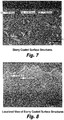
- FIGs. 5-8 are photomicrographs depicting interior component surfaces that have been coated using a conventional slurry coating process, under the same process conditions used to obtain the coating shown in Figs. 1-4 . It is readily apparent that coatings applied using a slurry are distributed in a discontinuous manner and possess a random saw toothed surface structure. This result is largely due to a low melting aluminum alloy source becoming unevenly distributed within the slurry during the coating process.
Landscapes
- Chemical & Material Sciences (AREA)
- Chemical Kinetics & Catalysis (AREA)
- Engineering & Computer Science (AREA)
- Materials Engineering (AREA)
- Mechanical Engineering (AREA)
- Metallurgy (AREA)
- Organic Chemistry (AREA)
- Turbine Rotor Nozzle Sealing (AREA)
Description
- This application claims the benefit of priority of United States Provisional Application No.
61/404,981, filed October 13, 2010 - The subject invention is directed generally to diffusion aluminide coatings, and more particularly, to a homogenous paste for applying a diffusion aluminide coating to a selected surface of a turbine component and to a method of applying a diffusion aluminide coating to a selected surface of a turbine component.
- In gas turbine engines, the vanes, buckets and blades are typically made of nickel-based superalloys that operate at temperatures reaching 982°C - 1149°C (1800-2100°F). Many approaches have been used to increase the operating temperature limit of these turbine components. In one approach, internal cooling passages are formed within the interior of the turbine component. Air is forced through the cooling passages and out openings at the external surface of the component, removing heat from the interior of the component. The surfaces of the internal cooling passages are often provided with a protective coating. Aluminide diffusion coatings are commonly used for this purpose.
- Those skilled in the art will readily appreciate that the internal surfaces of a turbine component are subjected to a significantly different service environment than the external surfaces of the component. The external surfaces experience hot corrosion, hot oxidation, and erosion in the combustion gas. In order to cool the operating temperature of the component, a flow of bleed air from the engine compressor, (not combustion gas), is passed through the internal passages. This assures the internal surfaces are at a lower temperature than the external surfaces. In some operating conditions, the cooling air may contain salt, sulfur, and other contaminants. The presence of salt and sulfur at a temperature in the range of about 704°C (1300°F), a typical temperature for the internal surfaces, may lead to severe hot corrosion on the internal surfaces. The internal surfaces of the gas turbine components are thus subjected to environmental damage of a type substantially different from that experienced on the external surfaces of a turbine component.
- The protection of the internal surfaces poses a substantially different problem than the protection of the external surfaces of the gas turbine component. The internal surfaces are usually formed by small internal passages, that are typically from about 0.25cm (0.1 inch) to about 1.27cm (0.5 inch) in diameter, and they are not readily accessible to many conventional exterior surface coating techniques. Consequently, the protective layer on the internal surfaces cannot be readily repaired, and therefore must last longer than the protective layer on the external surfaces, which can be more readily refurbished. Current techniques for coating the interior surfaces of a turbine component include pack cementation, vapor phase, and slurry coating processes. Pack cementation produces an adequate coating, but it is a costly, time consuming process. Slurry coating often produce a discontinuous coating with saw-toothed surface structures. Neither process is optimal. Vapor phase coatings can produce good coatings but the coating systems and tooling required high maintenance and are typically more expensive.
-
US 6 045 863 A ,EP 1 288 330 A1WO 00 00665 US 5 208 071 A ,US 2007 009660 A1 ,US 2004 115355 A1 andEP 2 060 653 A2 describe a coating for a metallic article in the form of a slurry.WO2005/035819 A1 discloses a method for local aluminizing metal components with a paste comprising a metal base component and an organic binder. - Thus, there is a need for improved, low cost, coating methods for protecting the internal surfaces of turbine components. The present invention fulfills this need, and further provides related advantages.
- The subject invention is directed to a new and useful homogenous paste for forming a protective coating on a substrate surface. In certain embodiments, the paste is useful for coating the internal surfaces of an article having internal and external surfaces. In particular embodiments, the paste is useful for coating the internal surfaces of interior cooling passages of a turbine component. In certain other embodiments, the paste may be useful for coating external surfaces as needed to meet component design requirements.
- The invention provides a homogenous coating paste for forming a protective diffusion aluminide coating on a substrate surface, comprising:
- a) a metallic base component;
- b) 40-50 wt.% of an organic binder based on the total amount of paste; and optionally
- c) a modifying element selected from the group of hafnium, yttrium, zirconium, chromium and/or silicon, and combinations thereof, or a solvent;
- i) Co2Al9, wherein Co2Al9 is from 1% to 50% by weight of the total metallic base component;
- ii) a halide activator, wherein the halide activator is from 0.1% to 5.0% by weight of the total metallic base component; and
- iii) an inert filler, wherein the inert filler is from 45% to 99% by weight of the total metallic base component.
- In still other embodiments, the halide activator of the coating paste is a non-hygroscopic halide activator. In particular embodiments, the halide activator of the coating paste is ammonium chloride, ammonium iodide, ammonium bromide, ammonium fluoride, ammonium bifluoride, elemental iodine, elemental bromine, hydrogen bromide, aluminum chloride, aluminum fluoride, aluminum bromide, or aluminum iodide. In specific embodiments, the halide activator of the coating paste is AlF3.
- The homogenous coating paste of the invention comprises an organic binder and an inert filler. The organic binder consists of methyl cellulose and de-ionized water. Similarly, in such an embodiment, the inert filler is aluminum oxide (Al2O3), kaolin, MgO, SiO2, Y2O3 or Cr2O3. In particular embodiments, the inert filler is Al2O3.
- In yet other embodiments, the ratio of metallic base component to organic binder in the homogenous coating paste of the invention is about 1:10, about 1:5, or about 1:2. In another embodiment, the ratio of metallic base component to organic binder in the homogenous coating paste of the invention is about 1:1.
- In still other embodiments, the homogenous coating paste of the invention comprises Co2Al9 from about 3% to about 40% by weight of the total metallic base component, or from about 5% to about 30% by weight of the total metallic base component.
- In yet other embodiments, the homogenous coating paste of the invention comprises halide activator from about 0.5% to about 4.0% by weight of the total metallic base component, or from about 1% to about 3% by weight of the total metallic base component.
- In particular embodiments, the homogenous coating paste of the invention comprises Co2Al9 from about 3% to about 40% by weight of the total metallic base component and halide activator from about 0.5% to about 4.0% by weight of the total metallic base component, or Co2Al9 from about 5% to about 30% by weight of the total metallic base component and halide activator is from about 1% to about 3% by weight of the total metallic base component.
- In another aspect, the subject invention is also directed to a new and useful method of applying a protective diffusion aluminide coating on the internal surfaces of an article having internal and external surfaces according to claim 13. The subject invention is directed to a new and useful method of applying a protective diffusion aluminide coating on the internal surfaces of the cooling passages of a turbine component, which includes the steps of injecting a coating paste according to claim 1 into the cooling passages of the turbine component, curing the coating paste in a temperature range of about 66°C to 93°C (150°F to 200°F) to stabilize the material, and then heating the turbine component in a furnace within a predetermined temperature range of about between 816°C and 1093°C (1500°F and 2000°F) for a sufficient time period to obtain a desired aluminide coating on the internal surfaces of the cooling passages. The method further includes the step of removing any residual paste from the cooling passages after it is removed from the furnace. This may be done using air or fluid.
- In certain embodiments, the method further includes the steps of heat treating the turbine component to produce a desired coating thickness and microstructure, and finishing the turbine component to obtain a desired surface appearance. It is envisioned that the internal surfaces of the cooling passages can be treated or otherwise prepared before injecting the paste into said passages to enhance coating adhesion.
- In another aspect, the subject invention is also directed to a new and useful method of applying a protective coating on the external surface of an article, which includes the steps of applying a coating paste according to
claim 1 into the external surface of the article, curing the coating paste in a temperature range of about 66°C to 93°C (150°F to 200°F) to stabilize the material, and then heating the article in a furnace within a predetermined temperature range of about between 816°C and 1093°C (1500°F and 2000°F) for a sufficient time period to obtain a desired aluminide coating on the internal surfaces of the cooling passages. The method further includes the step of removing any residual paste from the article after it is removed from the furnace. This may be done using air or fluid. - In certain embodiments, the coating paste is applied by any conventional means such as dipping the article in the paste, spreading the paste over the surface of the article or spraying the paste onto the surface of the article.
- In certain embodiments, the method further includes the steps of heat treating the article to produce a desired coating thickness and microstructure, and finishing the article to obtain a desired surface appearance. It is envisioned that the external surfaces of the article can be treated or otherwise prepared before applying the paste to enhance coating adhesion.
- These and other aspects of the subject invention will become more readily apparent from the following detailed description of the embodiments taken in conjunction with the drawings.
- So that those having ordinary skill in the art to which the subject invention pertains will more readily understand how to employ the coating process of the subject invention, particular embodiments thereof will be described in detail hereinbelow with reference to the drawings, wherein:
-
Fig. 1 is a photomicrograph illustrating a radial cooling passage surface of a turbine component coated in accordance with a particular embodiment of the subject invention, wherein the coating thickness is about 0.05mm (2 mils); -
Fig. 2 is a photomicrograph illustrating a radial cooling passage surface of a turbine component coated in accordance with a particular embodiment of the subject invention, wherein the coating thickness is about 0.025mm (1 mil); -
Fig. 3 is a photomicrograph illustrating a convoluted surface of an interior cooling passage of a turbine component coated in accordance with a particular embodiment of the subject invention; -
Fig. 4 is a photomicrograph illustrating a localized view of the coated convoluted surface shown inFig. 3 ; -
Fig. 5 is a photomicrograph illustrating a radial cooling passage surface of a turbine component that has been slurry coated using commercially available materials; -
Fig. 6 is a photomicrograph illustrating a localized view of the slurry coated surface structures shown inFig. 5 ; -
Fig. 7 is a photomicrograph illustrating slurry coated surface structures; -
Fig. 8 is a photomicrograph illustrating a localized view of the slurry coated surface strictures shown inFig. 7 ; -
Fig. 9 is an illustration of an apparatus constructed for injecting an aluminide coating paste into the internal passages of a turbine component; -
Fig. 10 is an illustration of an apparatus constructed for injecting an aluminide coating paste onto a component to be coated which uses a pressure vessel apparatus that stores and delivers the paste material in the manner described above while maintaining a consistent viscosity; -
Fig. 11 is a process flow chart illustrating the steps taken in performing the paste coating process of the subject invention; and -
Fig. 12 is a photograph of a sample sBlade Airfoil Section used in the comparative coating testing described in the Examples. - The subject invention is directed to a new and useful homogenous paste for forming a protective diffusion aluminide coating on a substrate surface.
- In a particular embodiment, the homogenous paste of the invention is useful for depositing a protective coating on the internal surfaces of interior cooling passages of a turbine component, such as a vane, nozzle, bucket or blade which is made from a cobalt-based or nickel-based superalloy. It is envisioned that the homogenous paste disclosed herein can also be employed for coating selective exterior surface of an article such as a turbine component.
- In addition, the subject invention is directed to a process of applying a diffusion aluminide coating to an interior surface of a turbine component using the homogenous paste of the subject invention. Each of these aspects of the subject invention will be described in detail hereinbelow.
- The invention provides a coating paste as disclosed in
claim 1 comprising Co2Al9, a halide activator, and an organic binder and an inert filler. - The Co2Al9 is carried by the organic binder and/or the inert filler for facilitating transfer of the aluminum in the Co2Al9 to the substrate surface during a coating process.
- The coating paste of the invention comprises a halide activator. In certain embodiments, the halide activator used for aluminum transfer is a hygroscopic halide activator. In other embodiments, the halide activator used for aluminum transfer is a non-hygroscopic halide activator. In certain embodiments, halide activators include halide sources such as sources of fluorine, chlorine, iodine, and bromine. Halide activators include, but are not limited to, ammonium chloride, ammonium iodide, ammonium bromide, ammonium fluoride, ammonium bifluoride, elemental iodine, elemental bromine, hydrogen bromide, aluminum chloride, aluminum fluoride, aluminum bromide, and aluminum iodide. In particular embodiments, the halide activator is aluminum fluoride (AlF3). In particular, aluminum fluoride is stable at desired coating temperatures, and given its hygroscopic properties, provides the paste with extended shelf life relative to other halide activators known in the art, such as ammonium bromide, ammonium chloride and or ammonium fluoride.
- The coating paste of the invention comprises an organic binder. The selected binder should be chosen to be unreactive (inert) with the metallic aluminum alloy and the halide activator. The binder should be chosen to not dissolve the activator. A binder should be selected to promote an adequate shelf-life for the paste. A selected binder should also burn off cleanly and completely early in the coating process without interfering with the aluminization reactions. The organic binder is methyl cellulose and de-ionized water.
- The coating paste also comprises an inert filler capable of preventing the metallic aluminum alloy from sintering when heated during the coating process. In certain embodiments, the inert filler includes alumina or aluminum oxide (Al2O3), kaolin, MgO, SiO2, Y2O3 or Cr2O3. The inert fillers may be used singly or in combination. In particular embodiments, the inert materials have a non-sintered, flowable grain structure. In specific embodiments, the filler is Al2O3.
- In certain embodiments, the paste can also include a modifying element such as, for example, hafnium, yttrium, zirconium, chromium, and/or silicon, and combinations thereof.
- In certain embodiments, the paste can also include a solvent. Suitable solvents include, but are not limited to, lower alcohols, N-methylpyrrolidone (NMP), and water to produce binder solutions having a wide range of viscosities. "Lower alcohols" are understood to be C1 -C6 alcohols, such as ethyl alcohol and isopropyl alcohol. Other commercially available solvents are acceptable for the subject invention. The solvent's volatility, flammability, and toxicity are important commercial criteria to consider in selecting a solvent.
- In accordance with another embodiment of the subject invention, different paste blends may be used to obtain a desired aluminide coating result on an internal surface of a cooling passage. In other words, the thickness and composition can be readily modified to suit a customer's requirements or a particular product design or coating specification. In particular embodiments, the coating paste of the invention has a viscosity between about 1,000 and about 250,000 centipoise.
- In another aspect, the coating paste of the invention is prepared by first mixing the metallic aluminum alloy, the halide activator and the inert filler to form a metallic base component. The metallic base component is then mixed with the organic binder to form the coating paste of the invention. The metallic base component and the organic binder can be mixed by any conventional means known to those of skill in the art including, but not limited to, the use of inline mixers, batch mixers, high shear mixers, jet mixers, agitators, ball mills, colloid mills, cone mills, or kneaders.
- In certain embodiments, the coating paste of the invention comprises metallic base component and organic binder in a ratio of about 1:10, about 1:5, about 1:3, about 1:2, or about 1:1 (metallic base component to organic binder).
- The metallic base component comprises from about 1 wt% to about 50 wt% of Co2Al9. In other embodiments, the metallic base component comprises from about 3 wt% to about 40 wt % of Co2Al9. In still other embodiments, the metallic base component comprises from about 5 wt% to about 30 wt% of Co2Al9. In particular embodiments, the metallic base component comprises, 5 wt%, 6 wt%, 7 wt%, 8 wt%, 9 wt%, 10 wt%, 11 wt%, 12 wt%, 13 wt%, 14 wt%, 15 wt%, 16 wt%, 17 wt%, 18 wt%, 19 wt%, 20 wt%, 21 wt%, 22 wt%, 23 wt%, 24 wt%, 25 wt%, 26 wt%, 27 wt%, 28 wt%, 29 wt%, or 30 wt% of Co2Al9.
- The metallic base component of the invention comprises from about 0.1 wt% to about 5.0 wt% of halide activator. In other embodiments, the metallic base component comprises from about 0.5 wt% to about 4.0 wt % of halide activator. In still other embodiments, the metallic base component comprises from about 1 wt% to about 3 wt% of halide activator. In particular embodiments, the metallic base component comprises, 0.5 wt%, 1 wt%, 1.5 wt%, 2.0 wt%, 2.5 wt%, 3.0 wt%, 3.5 wt%, 4.0 wt%, 4.5 wt%, or 5.0 wt% of halide activator.
- The metallic base component of the invention comprises from about 45 wt% to about 99 wt% of inert filler. In other embodiments, the metallic base component comprises from about 55 wt% to about 97 wt% of inert filler. In still other embodiments, the metallic base component comprises from 65 wt% to about 94 wt% of inert filler. In particular embodiments, the metallic base component comprises, 45 wt%, 50 wt%, 55 wt%, 60 wt%, 65 wt%, 70 wt%, 75 wt%, 80 wt%, 85 wt%, 90 wt%, or 95.0 wt% of inert filler.
- In particular embodiments, the paste comprises from 5-30 wt% of Co2Al9 and from 1-5 wt% of the halide depending upon the coating thickness and/or microstructure that is desired.
- It will be apparent to one of skill in the art that the process can be tailored to deposit uniformly thick aluminides of different thicknesses and surface structures including inward surface structures, outward surface structures or hybrid inward/outward surface structures.
- Referring to
Fig. 9 , there is illustrated an apparatus for filling the interior cooling passage of a turbine component with coating paste.Apparatus 100 includes a mountingfixture 120 for supporting aturbine component 110 having interior cooling passage (not shown). The mountingfixture 120 includes aninlet side 122 for receiving coating paste from ahorizontal feed conduit 124 and anoutlet side 126 for delivering coating paste into the cooling passages of aturbine component 110. It is envisioned that theoutlet side 126 would include one or more outlet ports communicating with a corresponding number of cooling passages formed in the component. Typically, a turbine blade or bucket includes a serpentine leading edge cooling circuit, a serpentine trailing edge cooling circuit and up to twelve discrete radial cooling passage that extend from the root of the component to the tip of the component. Thus, the outlet side of the fixture would have a corresponding number of outlet ports to accommodate the number, size and shape of the cooling passages. - The
paste injection apparatus 100 further includes ahopper 130 for storing a sufficient volume of coating paste to fill a plurality of turbine components without replenishment. Thehopper 130 preferably feeds paste into avertical feed conduit 132 under gravity. However, it is envisioned that a weight or plunger may be provided within thehopper 130 to forcibly drive the paste intovertical feed conduit 132.Injection apparatus 100 further includes apump assembly 140 that includes acharging cylinder 142 having areciprocating piston 144 and aninjection conduit 146. The charging cylinder is designed to accumulate coating paste from thehopper 130 when thepiston 144 is drawn rearwardly and to deliver the paste to thefixture 120 when thepiston 144 is driven forward. Thepump assembly 140 further includes apneumatic pump cylinder 148 for actuating thepiston 144. - The
paste filling apparatus 100 further includes acontrol valve 150 in fluid communication with thehorizontal feed conduit 124 offixture 120, thevertical feed conduit 132 of thehopper 130 and theinjection conduit 146 ofpump assembly 140 for controlling the flow of coating paste therebetween. In one position, thecontrol valve 150 permits paste to be drawn from thehopper 130 into the chargingcylinder 142, while preventing paste from traveling into thehorizontal feed conduit 124 leading to theinlet side 122 offixture 120. In another position, thecontrol valve 150 permits paste to travel from theinjection conduit 146 into thehorizontal feed conduit 124, while blocking off thevertical feed conduit 132 leading fromhopper 130. The control valve may be manually operated or automatically actuated. Thepump cylinder 148 is adapted and configured to deliver paste at a rate of about 200 gms/min and at a supply pressure of about between 0.138 MPa and 0.345 MPa (20 psi and 50 psi). - Referring to
Fig. 10 there is illustrated an apparatus for filling the interior cooling passage of a turbine component with coating paste, which is designated generally byreference numeral 200. This system uses a pressure vessel that contains the paste material and is mixed to maintain a consistent viscosity. In certain embodiments, the paste material is mixed at regular intervals and for a set period of time. In certain other embodiments, the paste material is mixed continuously. -
Apparatus 200 includes a mountingfixture 220 for supporting aturbine component 210 having interior cooling passage (not shown). The mountingfixture 220 includes an inlet side control valve 221 for receiving coating paste from a conduit, such as a rigid or flexible tube, 230 and anoutlet side 222 for delivering coating paste into the cooling passages of aturbine component 210. It is envisioned that theoutlet side 222 would include one or more outlet ports communicating with a corresponding number of cooling passages formed in the component. Typically, a turbine blade or bucket includes a serpentine leading edge cooling circuit, a serpentine trailing edge cooling circuit and up to twelve discrete radial cooling passage that extend from the root of the component to the tip of the component. Thus, the outlet side of the fixture would have a corresponding number of outlet ports to accommodate the number, size and shape of the cooling passages. - The
paste injection apparatus 200 further includes ahopper 240 for storing a sufficient volume of coating paste to fill a plurality of turbine components without replenishment. Thehopper 240 preferably feeds paste into theconduit 230 through avertical feed tube 250 and aconduit connector 251. In certain embodiments, thehopper 240 is composed of acontainer 241 and acover 242 which is secured by a plurality of clamps orbolts 243 which are capable of sealing the container and maintaining an increased pressure. - The paste is pressure fed into the feed tube, typically by the addition of pressurized gas, such as compressed air, nitrogen, argon, or hydrogen, through a
pressure inlet 260 equipped in thecover 242 of thehopper 240. The pressure inlet is equipped with a pressure regulator andgauge device 261. - The
hopper 240 is also equipped with amixing apparatus 270 comprising amixing device 271 attached to a mixingmotor 272 by a mixingshaft 273. The mixingshaft 273 passes through thecover 242 and is secured such that the seal is maintained by the cover while mixing. - The coating paste of the invention can be used to coat any desired article. In general, the coating paste is used to coat the internal surfaces of an article having an internal surface and an external surface, including, but not limited to, pipes, flexible or rigid tubes, flexible or rigid hoses, jet nozzles, propelling nozzles, spray nozzles, shaping nozzles, high velocity nozzles, vanes, blades, or buckets. In a particular embodiment, the article to be coated is a turbine component. In some embodiments, the coating paste can be used to coat the external surfaces of an article. In such embodiments, the paste can be applied by any means known to those of skill in the art including, but not limited to, spraying, dipping or spreading the coating onto the surface. Similarly, in such embodiments, the article would then be heated in a furnace within a predetermined temperature range of about between 816°C and 1149°C (1500°F and 2100°F) for a sufficient time period to obtain a desired aluminide coating on article to be coated.
- Referring now to
Fig. 11 , there is illustrated aflow chart 300 identifying the operative steps involved in the process of applying a protective coating to the internal surfaces of the cooling passages of a turbine component in accordance with a particular embodiment of the subject invention. Initially, if desired, the internal surfaces of the cooling passages can be treated or otherwise prepared before injecting the paste into the passages atstep 310, to enhance coating adhesion. This can be done using a liquid cleaning fluid or by way of ultrasonic cleaning to remove grease and oil from the surfaces. - At
step 320, an aluminide paste is injected into the cooling passages of the turbine component and cured. This can be accomplished utilizing theinjection apparatus 100 described above and illustrated inFig. 9 or theinjection apparatus 200 described above and illustrated inFig. 10 . Alternative injection devices and filling methods can also be employed. The aluminide paste is cured at a temperature in the range of about 66°C to 93°C (150°F to 200°F) to stabilize the material. This causes the water in the paste to evaporate before its boils, which can create unwanted voids in the paste. - Then, at
step 320 the turbine component is heated in a furnace within a predetermined temperature range of about between 816°C and 1149°C (1500°F and 2100°F) for a sufficient time period to obtain a desired aluminide coating on the internal surfaces of the cooling passages. As the component is heated in the furnace, the binder system is vaporized, turning to ash, at temperatures well below a relevant coating temperature. The latent halide activator AlF3 then reacts at a higher temperature with the aluminum alloy Co2Al9 to deposit aluminum on the interior substrate surfaces and thereby form the diffusion aluminide coating. - During the thermal cycle of
step 330, the time period for heating the turbine component within the furnace can vary from 2 to 8 hours, although it is preferable to heat the component for a period of about between 4 to 6 hours. The extent of the time period depends largely upon amount of aluminum alloy that is available in the paste for diffusion onto the substrate surfaces.Process step 330 is performed in a controlled atmosphere such as argon or hydrogen, and in full vacuum or under partial pressure. - The method further includes the
step 340 of removing any residual paste or ash from the cooling passages after it is removed from the furnace. This may be done using forced air or a fluid wash, and then the component may be rinsed or dried as necessary. Because the paste coating process of the subject invention utilizes a relatively viscous coating media that can be injected into the interior cooling passage of a turbine component in a controlled manner, there is little if any aluminide bleed on to the exterior surfaces of the component not requiring coating. This characteristic is useful when applied to a turbine component that requires internal aluminide coating and an external metallic or combination metallic/ceramic thermal barrier (TBC) coating. The external coating systems typically applied by a thermal spray process must be free of aluminide coating to assure the adhesion properties of the coating. If aluminide coating is present, (a typical result with vapor phase or pack cementation) it must be removed by mechanical or chemical stripping prior to the thermal spray coating application. Due to the precise application of the subject invention the coating removal step would not be required and thus lower the overall cost of the component coating processes. - The method further includes the steps of heat treating the turbine component at
step 350 to produce a desired coating thickness and microstructure, and finishing the turbine component atstep 360 to obtain a desired surface appearance. The resulting protective coating is adherent to base alloy and has a uniform continuous surface free from chipping, cracking, spalling or adherent particles. The coating surface finish is typically of that which is obtained by pack cementation and vapor phase processes. In the course of the coating run, coating analysis is preferably performed using representative samples. - In sum, the paste compositions and process of the subject invention produces coating thicknesses, microstructures, and aluminide content similar to the current available pack cementation or vapor coating processes without the variation in coating distribution or the high costs associated with VPA/CVD tooling. Unlike the disadvantages of a pack cementation powder process, the paste media of the subject invention does not lose its chemical consistency when it is injected into internal passages of a turbine component. This characteristic produces a uniform coating distribution on all surfaces. In addition, the paste is able to produce acceptable coatings in components with various levels for surface oxides or scale. This is an advantage when coating engine run overhaul components or parts with debris from previous processing operations that may inhibit the diffusion process.
- The structures, materials, compositions, and methods described herein are intended to be representative examples of the invention, and it will be understood that the scope of the invention is not limited by the scope of the examples.
- The following examples illustrate various exemplary embodiments of the methods described in this disclosure.
- In general, the metallic base component is prepared through powder blending. Each component material (metallic aluminum alloy, halide activator and inert filler) is weighed based on the percentage of ingredient used and total weight of the metallic base component powder blend.
- In the coating pastes described below, the ingredients for the metallic base component powder blend were cobalt aluminum (Co2Al9), aluminum fluoride (AlF3) and aluminum oxide (Al2O3). All (3) ingredients were loaded into a powder blender and mixed for 30 - 60 minutes. After blending, the mixture was given a batch identifier and was ready for use in preparing the coating paste
- 4000 ml of deionized water was added into a Hobart mixing bowl. 50 grams of methyl cellulose powder was measured. The mixer was set to run at setting #1. A small amount of methyl cellulose powder was sprinkled into the mixing bowl. Small amounts of methyl cellulose powder were added into the mixing bowl until all 50 grams were added. The binder component was to mix for 1 - 1.5 hours or until the mixture appeared lump free. When complete, the mixture was poured into a clean bucket and capped for storage. The mixture was then given a batch identifier and allowed to sit for a minimum of 8 hours prior to use to remove all air bubbles.
- 2000 grams of the metallic base component powder blend was added to a Hobart mixing bowl. Next, 1500 grams of the binder component was added to the Hobart mixing bowl. The mixer was set to setting #1 and allowed blend for 15 minutes. After the mixing was complete, the paste was ready for use or storage. Fifteen representative blends of paste were prepared and are described in Table A below as Blend A - Blend O.
Table A Blend Metallic Base Component (MBC) % (of MBC) Metallic Base Component % (of total) Organic Binder (Methyl Cellulose and Deionized Water) % (of total) Cobalt Aluminum (Co2Al9)% Aluminum Fluoride (AlF3)% Inert Filler Aluminum Oxide (Al2O3)% Blend A 5 1 94 50% - 60% 40% - 50% Blend B 5 2 93 50% - 60% 40% - 50% Blend C 5 3 92 50% - 60% 40% - 50% Blend D 10 1 89 50% - 60% 40% - 50% Blend E 10 2 88 50% - 60% 40% - 50% Blend F 10 3 87 50% - 60% 40% - 50% Blend G 15 1 84 50% - 60% 40% - 50% Blend H 15 2 83 50% - 60% 40% - 50% Blend I 15 3 82 50% - 60% 40% - 50% Blend J 20 1 79 50% - 60% 40% - 50% Blend K 20 2 78 50% - 60% 40% - 50% Blend L 20 3 77 50% - 60% 40% - 50% Blend M 30 1 69 50% - 60% 40% - 50% Blend N 30 2 68 50% - 60% 40% - 50% Blend O 30 3 67 50% - 60% 40% - 50% - The turbine blade was loaded into a coating furnace. The coating furnace, parts/boxes or furnace racks were heated to the range of 816°C +/- 14°C (1500 °F +/- 25°F) to 1079°C +/-14°C (1975°F +/- 25°F) in a cover gas of argon or hydrogen or in vacuum or vacuum partial pressure for a sufficient time to meet desired coating requirements.
- The parts to be coated were air blown-out, water washed, scrubbed, rinsed and dried as required.
- Tables 1-12 show coating results for ten radial cooling passages formed in a Blade Airfoil Section (see
Fig. 12 ) using from 5-20 wt% Co2Al9 and from 1-3 wt% AlF3, and using identical coating process conditions and identical post-coating thermal cycle treatment. The tabulated results establish that the use of the subject aluminide paste having a controlled alloy/activator chemistry enables the user to have a high degree of control over the coating process, so as to obtain a desired aluminide coating thickness. In each of the tables, the coating thickness was measured in each of the 10 holes shown inFig. 12 . The average diameter of the holes was approximately 0.295cm (0.116 inches). - The test was conducted four times (Columns labeled 1, 2, 3, and 4) and the Average coating thickness, Maximum thickness, Minimum thickness and Standard Deviations were calculated and recorded.
Table 1 Coating Mix Blend A Hole # Average Coating Thickness Max Min Std- Dev 1 2 3 4 1 1.0 1.1 1.2 1.0 1.1 1.2 1.0 0.10 2 1.0 0.9 0.7 1.1 0.9 1.1 0.7 0.17 3 1.3 1.3 1.2 1.3 1.3 1.3 1.2 0.05 4 1.2 1.4 1.2 1.3 1.3 1.4 1.2 0.10 5 1.2 1.2 1.2 1.3 1.2 1.3 1.2 0.05 6 1.3 1.1 1.2 1.3 1.2 1.3 1.1 0.10 7 1.2 1.1 1.1 1.3 1.2 1.3 1.1 0.10 8 1.2 1.1 1.2 1.2 1.2 1.2 1.1 0.05 9 1.1 1.2 1.1 1.2 1.2 1.2 1.1 0.06 10 0.7 0.8 1.0 0.7 0.8 1.0 0.7 0.14 Table 2 Coating Mix Blend B Hole # Average Coating Thickness Max Min Std- Dev 1 2 3 4 1 1.4 1.3 1.5 1.4 1.4 1.5 1.3 0.08 2 1.3 1.3 1.5 1.3 1.4 1.5 1.3 0.10 3 1.2 1.1 1.3 1.4 1.3 1.4 1.1 0.13 4 1.0 1.4 1.6 1.3 1.3 1.6 1.0 0.25 5 1.2 1.3 1.4 1.5 1.4 1.5 1.2 0.13 6 1.2 1.3 1.5 1.2 1.3 1.5 1.2 0.14 7 1.2 1.3 1.3 1.3 1.3 1.3 1.2 0.05 8 1.2 1.1 1.5 1.3 1.3 1.5 1.1 0.17 9 1.2 1.2 1.3 1.3 1.3 1.3 1.2 0.06 10 0.7 0.8 0.8 0.6 0.7 0.8 0.6 0.10 Table 3 Coating Mix Blend C Hole # Average Coating Thickness Max Min Std- Dev 1 2 3 4 1 1.4 1.1 1.2 1.3 1.3 1.4 1.1 0.13 2 1.2 1.4 1.5 1.1 1.3 1.5 1.1 0.18 3 1.3 1.1 1.3 1.3 1.3 1.3 1.1 0.10 4 1.3 1.2 1.2 1.4 1.3 1.4 1.2 0.10 5 1.3 1.2 1.3 1.3 1.3 1.3 1.2 0.05 6 1.3 1.1 1.2 1.0 1.2 1.3 1.0 0.13 7 1.1 1.3 1.0 1.0 1.1 1.3 1.0 0.14 8 0.8 0.9 0.7 1.0 0.9 1.0 0.7 0.13 9 0.9 0.9 1.0 1.1 1.0 1.1 0.9 0.10 10 0.6 0.5 0.5 0.7 0.6 0.7 0.5 0.10 Table 4 Coating Mix Blend D Hole # Average Coating Thickness Max Min Std- Dev 1 2 3 4 1 1.4 1.6 1.7 1.5 1.6 1.7 1.4 0.13 2 1.5 1.5 1.3 1.5 1.5 1.5 1.3 0.10 3 1.5 1.6 1.5 1.6 1.6 1.6 1.5 0.06 4 1.7 1.6 1.6 1.5 1.6 1.7 1.5 0.08 5 1.5 1.3 1.7 1.5 1.5 1.7 1.3 0.16 6 1.3 1.5 1.5 1.5 1.5 1.5 1.3 0.10 7 1.4 1.5 1.5 1.4 1.5 1.5 1.4 0.06 8 1.3 1.3 1.4 1.4 1.4 1.4 1.3 0.06 9 1.3 1.2 1.6 1.5 1.4 1.6 1.2 0.18 10 1.0 1.2 1.0 1.0 1.1 1.2 1.0 0.10 Table 5 Coating Mix Blend E Hole # Average Coating Thickness Max Min Std- Dev 1 2 3 4 1 1.5 1.8 1.8 1.9 1.8 1.9 1.5 0.17 2 1.5 1.6 1.5 2.0 1.7 2.0 1.5 0.24 3 1.8 1.6 1.6 1.9 1.7 1.9 1.6 0.15 4 1.6 1.8 1.4 2.0 1.7 2.0 1.4 0.26 5 1.5 1.7 1.8 1.7 1.7 1.8 1.5 0.13 6 1.8 1.6 1.7 1.7 1.7 1.8 1.6 0.08 7 1.7 1.8 1.6 1.7 1.7 1.8 1.6 0.08 8 1.6 1.7 1.7 1.7 1.7 1.7 1.6 0.05 9 1.7 1.8 1.8 1.6 1.7 1.8 1.6 0.10 10 1.3 1.3 1.5 1.4 1.4 1.5 1.3 0.10 Table 6 Coating Mix Blend F Hole # Average Coating Thickness Max Min Std- Dev 1 2 3 4 1 1.7 1.8 1.8 2.0 1.8 2.0 1.7 0.13 2 1.5 1.6 1.8 1.8 1.7 1.8 1.5 0.15 3 1.5 1.7 1.6 2.0 1.7 2.0 1.5 0.22 4 1.6 1.8 1.5 1.9 1.7 1.9 1.5 0.18 5 1.5 1.6 1.7 1.8 1.7 1.8 1.5 0.13 6 1.4 1.7 1.8 1.5 1.6 1.8 1.4 0.18 7 1.5 1.7 2.0 1.7 1.7 2.0 1.5 0.21 8 1.5 1.8 1.5 1.7 1.6 1.8 1.5 0.15 9 1.5 1.6 1.7 1.6 1.6 1.7 1.5 0.08 10 1.4 1.6 1.5 1.3 1.5 1.6 1.3 0.13 Table 7 Coating Mix Blend G Hole # Average Coating Thickness Max Min Std- Dev 1 2 3 4 1 1.9 2.1 2.0 2.0 2.0 2.1 1.9 0.08 2 2.3 2.1 2.1 2.2 2.2 2.3 2.1 0.10 3 2.3 2.2 2.0 1.9 2.1 2.3 1.9 0.18 4 2.1 2.1 2.1 2.0 2.1 2.1 2.0 0.05 5 1.9 1.9 1.7 1.9 1.9 1.9 1.7 0.10 6 1.7 1.8 1.7 1.7 1.7 1.8 1.7 0.05 7 0.8 1.0 1.1 0.7 0.9 1.1 0.7 0.18 8 1.6 1.7 1.7 1.8 1.7 1.8 1.6 0.08 9 1.5 1.7 1.6 1.6 1.6 1.7 1.5 0.08 10 1.4 1.5 1.4 1.4 1.4 1.5 1.4 0.05 Table 8 Coating Mix Blend H Hole # Average Coating Thickness Max Min Std- Dev 1 2 3 4 1 1.7 2.1 1.8 2.3 2.0 2.3 1.7 0.28 2 2.1 2.0 2.3 1.8 2.1 2.3 1.8 0.21 3 2.3 2.5 2.0 1.9 2.2 2.5 1.9 0.28 4 1.8 2.2 1.9 2.1 2.0 2.2 1.8 0.18 5 2.3 2.0 1.8 2.1 2.1 2.3 1.8 0.21 6 2.3 2.1 2.0 2.2 2.2 2.3 2.0 0.13 7 2.1 2.0 2.2 2.1 2.1 2.2 2.0 0.08 8 1.8 1.6 2.2 1.9 1.9 2.2 1.6 0.25 9 2.0 2.2 2.3 1.8 2.1 2.3 1.8 0.22 10 2.1 1.7 1.9 1.8 1.9 2.1 1.7 0.17 Table 9 Coating Mix Blend I Hole # Average Coating Thickness Max Min Std- Dev 1 2 3 4 1 2.5 2.6 2.4 2.3 2.5 2.6 2.3 0.13 2 2.5 2.5 2.7 2.4 2.5 2.7 2.4 0.13 3 3.0 2.3 2.5 2.8 2.7 3.0 2.3 0.31 4 2.5 2.4 2.5 2.3 2.4 2.5 2.3 0.10 5 2.3 2.5 2.2 2.3 2.3 2.5 2.2 0.13 6 2.3 2.1 2.4 2.6 2.4 2.6 2.1 0.21 7 2.3 2.1 2.3 2.2 2.2 2.3 2.1 0.10 8 1.8 2.0 1.8 1.8 1.9 2.0 1.8 0.10 9 1.8 1.9 2.3 1.9 2.0 2.3 1.8 0.22 10 1.5 1.9 1.4 1.5 1.6 1.9 1.4 0.22 Table 10 Coating Mix Blend J Hole # Average Coating Thickness Max Min Std- Dev 1 2 3 4 1 1.4 1.3 1.5 1.3 1.4 1.5 1.3 0.10 2 1.2 1.1 1.3 1.3 1.2 1.3 1.1 0.10 3 1.3 1.4 1.2 1.2 1.3 1.4 1.2 0.10 4 2.0 1.7 1.6 2.0 1.8 2.0 1.6 0.21 5 1.4 1.3 1.3 1.3 1.3 1.4 1.3 0.05 6 1.3 1.2 1.3 1.5 1.3 1.5 1.2 0.13 7 1.7 2.0 1.8 1.8 1.8 2.0 1.7 0.13 8 1.3 1.3 1.4 1.5 1.4 1.5 1.3 0.10 9 1.1 1.4 1.3 1.4 1.3 1.4 1.1 0.14 10 0.6 0.8 0.9 0.7 0.8 0.9 0.6 0.13 Table 11 Coating Mix Blend K Hole # Average Coating Thickness Max Min Std- Dev 1 2 3 4 1 2.5 2.5 2.8 2.4 2.6 2.8 2.4 0.17 2 2.8 2.7 2.4 2.6 2.6 2.8 2.4 0.17 3 2.7 2.4 2.5 2.7 2.6 2.7 2.4 0.15 4 2.7 2.8 2.5 2.5 2.6 2.8 2.5 0.15 5 2.5 2.8 2.5 2.6 2.6 2.8 2.5 0.14 6 2.5 2.7 2.6 2.6 2.6 2.7 2.5 0.08 7 2.3 2.5 2.6 2.4 2.5 2.6 2.3 0.13 8 2.3 2.4 2.5 2.3 2.4 2.5 2.3 0.10 9 2.3 2.3 2.8 2.6 2.5 2.8 2.3 0.24 10 2.3 2.4 2.2 2.3 2.3 2.4 2.2 0.08 Table 12 Coating Mix Blend L Hole # Average Coating Thickness Max Min Std- Dev 1 2 3 4 1 3.5 3.5 3.2 3.5 3.4 3.5 3.2 0.15 2 3.2 3.3 3.2 3.1 3.2 3.3 3.1 0.08 3 3.3 3.4 3.5 3.2 3.4 3.5 3.2 0.13 4 3.4 3.5 3.5 3.3 3.4 3.5 3.3 0.10 5 3.5 3.3 3.5 3.4 3.4 3.5 3.3 0.10 6 2.9 2.8 2.9 2.8 2.9 2.9 2.8 0.06 7 2.8 2.9 3.0 3.0 2.9 3.0 2.8 0.10 8 2.6 2.6 2.5 2.6 2.6 2.6 2.5 0.05 9 2.6 3.1 2.9 2.8 2.9 3.1 2.6 0.21 10 2.1 2.7 1.8 2.2 2.2 2.7 1.8 0.37 - Referring now to
Figs. 1-4 , there is illustrated a series of photomicrographs depicting aluminide coatings applied to different interior surfaces of a turbine component using the coating paste and process of the subject invention. In particular,Figs. 1 and 2 depict aluminide coatings having respective thicknesses of 0.05mm (2 mils) and 0.025mm (1 mil), applied to the interior surfaces of radial cooling passages.Fig. 3 is a photomicrograph depicting an aluminide coating applied to the surface of a convoluted cooling passage, andFig. 4 is an enlarged localized view of the peak of the convolution shown inFig. 3 . It is readily apparent fromFigs. 1-4 , that the paste coating process of the subject invention produces a smooth continuous aluminide coating on the substrate surface. - By way of comparison,
Figs. 5-8 are photomicrographs depicting interior component surfaces that have been coated using a conventional slurry coating process, under the same process conditions used to obtain the coating shown inFigs. 1-4 . It is readily apparent that coatings applied using a slurry are distributed in a discontinuous manner and possess a random saw toothed surface structure. This result is largely due to a low melting aluminum alloy source becoming unevenly distributed within the slurry during the coating process.
Claims (15)
- A homogenous paste for forming a protective diffusion aluminide coating on a substrate surface, comprising:(a) a metallic base component;(b) 40-50 wt.% of an organic binder based on the total amount of paste; and optionally(c) a modifying element selected from the group of hafnium, yttrium, zirconium, chromium and/or silicon, and combinations thereof or a solvent;
characterized in that the organic binder consists of methyl cellulose and de-ionized water and said metallic base component consists of:(i) Co2Al9, wherein Co2Al9 is from 1% to 50% by weight of the total metallic base component;(ii) a halide activator, wherein the halide activator is from 0.1% to 5.0% by weight of the total metallic base component; and(iii) an inert filler, wherein the inert filler is from 45% to 99% by weight of the total metallic base component. - The homogenous coating paste of Claim 1, wherein the halide activator is a non-hygroscopic halide activator.
- The homogenous coating paste of claim 1 or claim 2, wherein the halide activator is ammonium chloride, ammonium iodide, ammonium bromide, ammonium fluoride, ammonium bifluoride, elemental iodine, elemental bromine, hydrogen bromide, aluminium chloride, aluminium fluoride, aluminium bromide, or aluminium iodide.
- The homogenous coating paste of any one of Claims 1-3, wherein the halide activator is AlF3.
- The homogenous paste of any one of Claims 1-4, wherein the inert filler is aluminium oxide (Al2O3), kaolin, MgO, SiO2, Y2O3 or Cr2O3, preferably wherein the inert filler is Al2O3.
- The homogenous coating paste of Claims 1-5, wherein the ratio of metallic base component to organic binder is about 1:1.
- The homogenous coating paste of any one of Claims 1-6, wherein Co2Al9 is from 3% to 40% by weight of the total metallic base component.
- The homogenous coating paste of any one of Claims 1-7, wherein Co2Al9 is from 5% to 30% by weight of the total metallic base component.
- The homogenous coating paste of any one of Claims 1-8, wherein the halide activator is from 0.5% to 4.0% by weight of the total metallic base component.
- The homogenous coating paste of any one of Claims 1-9, wherein the halide activator is from 1% to 3% by weight of the total metallic base component.
- The homogenous coating paste of any one of Claims 1-10, wherein Al2O3 is from 55% to 97% by weight of the total metallic base component.
- The homogenous coating paste of any one of Claims 1-11, wherein Al2O3 is from 65% to 94% by weight of the total metallic base component.
- A method of applying a protective diffusion aluminide coating on the internal surfaces or on the external surface of an article to be coated, said article having at least one internal and at least one external surface and said internal and external surfaces forming at least one internal passage, comprising the steps of:(a) injecting a paste according to Claim 1 into the internal passages of the article and/or applying the paste onto the external surface of the article;(b) curing the paste;(c) heating the article in a furnace to obtain an aluminide coating on the internal surfaces of article and/or on the external surfaces of the article; and(d) removing residual paste from the article.
- The method according to Claim 13, wherein the article is a turbine component and the internal passages are the cooling passages of the turbine component.
- The method according to Claim 13 or Claim 14, further comprising at least one of:-the step of heat treating the article to produce a desired coating thickness and microstructure;
the step of finishing the article component;
the step of preparing the internal surfaces of article before injecting the paste into the article.
Applications Claiming Priority (2)
| Application Number | Priority Date | Filing Date | Title |
|---|---|---|---|
| US40498110P | 2010-10-13 | 2010-10-13 | |
| US13/267,281 US20120094021A1 (en) | 2010-10-13 | 2011-10-06 | Method of forming a diffusion aluminide coating on a surface of a turbine component and a homogeneous paste for coating such surfaces |
Publications (3)
| Publication Number | Publication Date |
|---|---|
| EP2441855A2 EP2441855A2 (en) | 2012-04-18 |
| EP2441855A3 EP2441855A3 (en) | 2012-05-09 |
| EP2441855B1 true EP2441855B1 (en) | 2019-11-27 |
Family
ID=45418536
Family Applications (1)
| Application Number | Title | Priority Date | Filing Date |
|---|---|---|---|
| EP11250846.0A Active EP2441855B1 (en) | 2010-10-13 | 2011-10-12 | Method of forming a diffusion aluminide coating on a surface of a turbine component and a homogeneous paste for coating such surfaces |
Country Status (2)
| Country | Link |
|---|---|
| US (1) | US20120094021A1 (en) |
| EP (1) | EP2441855B1 (en) |
Families Citing this family (8)
| Publication number | Priority date | Publication date | Assignee | Title |
|---|---|---|---|---|
| US9783880B2 (en) | 2013-12-19 | 2017-10-10 | General Electric Company | Slurry and a coating method |
| RU2556455C1 (en) * | 2014-03-13 | 2015-07-10 | Государственное научное учреждение Всероссийский научно-исследовательский технологический институт ремонта и эксплуатации машинно-тракторного парка Российской академии сельскохозяйственных наук (ГНУ ГОСНИТИ РОССЕЛЬХОЗАКАДЕМИИ) | Part surface alloying process |
| FR3029535B1 (en) | 2014-12-03 | 2017-01-06 | Snecma | PROCESS FOR MANUFACTURING A COVERED PART WITH A PROTECTIVE COATING |
| CN104801465A (en) * | 2015-03-16 | 2015-07-29 | 苏州优逸克智能科技有限公司 | Rotary dispensing valve |
| US10030298B2 (en) | 2015-08-21 | 2018-07-24 | General Electric Company | Method for altering metal surfaces |
| DE102016009854A1 (en) * | 2016-08-12 | 2018-02-15 | Dechema Forschungsinstitut Stiftung Bürgerlichen Rechts | Long-term stable, storable slip for environmentally friendly diffusion coatings |
| US10077494B2 (en) * | 2016-09-13 | 2018-09-18 | General Electric Company | Process for forming diffusion coating on substrate |
| US20180087141A1 (en) * | 2016-09-28 | 2018-03-29 | General Electric Company | Method for treating coated article and treated article |
Citations (2)
| Publication number | Priority date | Publication date | Assignee | Title |
|---|---|---|---|---|
| GB1431355A (en) * | 1972-07-05 | 1976-04-07 | Cockerill | Diffusing metals into low-carbon steel sheet |
| WO2005035819A1 (en) * | 2003-10-11 | 2005-04-21 | Mtu Aero Engines Gmbh | Method for local alitising, siliconising and chroming of metal components |
Family Cites Families (13)
| Publication number | Priority date | Publication date | Assignee | Title |
|---|---|---|---|---|
| DE3171006D1 (en) * | 1981-06-03 | 1985-07-25 | Walbar Metals Inc | Diffusion coating composition and method |
| US5208071A (en) * | 1990-02-28 | 1993-05-04 | The Babcock & Wilcox Company | Method for aluminizing a ferritic workpiece by coating it with an aqueous alumina slurry, adding a halide activator, and heating |
| US5284296A (en) * | 1991-12-12 | 1994-02-08 | Magneco/Metrel, Inc. | System for spraying ceramic slurries onto surfaces in contact with molten metals |
| EP0567755B1 (en) * | 1992-04-29 | 1996-09-04 | WALBAR INC. (a Delaware Corporation) | Improved diffusion coating process and products |
| JP3348204B2 (en) * | 1994-04-20 | 2002-11-20 | 三菱アルミニウム株式会社 | Method and apparatus for producing long material with brazing powder |
| US6022632A (en) * | 1996-10-18 | 2000-02-08 | United Technologies | Low activity localized aluminide coating |
| US5997604A (en) * | 1998-06-26 | 1999-12-07 | C. A. Patents, L.L.C. | Coating tape |
| US6730179B2 (en) * | 2001-08-31 | 2004-05-04 | Sermatech International Inc. | Method for producing local aluminide coating |
| US7056555B2 (en) * | 2002-12-13 | 2006-06-06 | General Electric Company | Method for coating an internal surface of an article with an aluminum-containing coating |
| US7390534B2 (en) * | 2003-10-31 | 2008-06-24 | General Electric Company | Diffusion coating process |
| JP3757418B1 (en) * | 2005-01-19 | 2006-03-22 | 石川島播磨重工業株式会社 | Method for local application of diffusion aluminide coating |
| US20100136240A1 (en) * | 2007-05-07 | 2010-06-03 | O'connell Matthew James | Process for Forming an Outward Grown Aluminide Coating |
| US8916005B2 (en) * | 2007-11-15 | 2014-12-23 | General Electric Company | Slurry diffusion aluminide coating composition and process |
-
2011
- 2011-10-06 US US13/267,281 patent/US20120094021A1/en not_active Abandoned
- 2011-10-12 EP EP11250846.0A patent/EP2441855B1/en active Active
Patent Citations (2)
| Publication number | Priority date | Publication date | Assignee | Title |
|---|---|---|---|---|
| GB1431355A (en) * | 1972-07-05 | 1976-04-07 | Cockerill | Diffusing metals into low-carbon steel sheet |
| WO2005035819A1 (en) * | 2003-10-11 | 2005-04-21 | Mtu Aero Engines Gmbh | Method for local alitising, siliconising and chroming of metal components |
Also Published As
| Publication number | Publication date |
|---|---|
| EP2441855A3 (en) | 2012-05-09 |
| US20120094021A1 (en) | 2012-04-19 |
| EP2441855A2 (en) | 2012-04-18 |
Similar Documents
| Publication | Publication Date | Title |
|---|---|---|
| EP2441855B1 (en) | Method of forming a diffusion aluminide coating on a surface of a turbine component and a homogeneous paste for coating such surfaces | |
| EP2060653B1 (en) | Slurry diffusion aluminide coating composition and process | |
| US5366765A (en) | Aqueous slurry coating system for aluminide coatings | |
| US5824366A (en) | Slurry coating system | |
| US6485780B1 (en) | Method for applying coatings on substrates | |
| US10156007B2 (en) | Methods of applying chromium diffusion coatings onto selective regions of a component | |
| EP2172579B1 (en) | Mixture and technique for coating an internal surface of an article | |
| US8973808B2 (en) | Method for making a cellular seal | |
| CN101403103B (en) | Method for aluminising the hollow metal parts of a turbomachine in vapour phase | |
| US20160047029A1 (en) | Method and Apparatus for Depositing Protective Coatings and Components Coated Thereby | |
| EP3094758B1 (en) | Modified slurry compositions for forming improved chromium diffusion coatings | |
| US7390534B2 (en) | Diffusion coating process | |
| US6299935B1 (en) | Method for forming a coating by use of an activated foam technique | |
| EP1361338B1 (en) | Dimensionally controlled pack aluminiding of internal surfaces of a hollow gas turbine blade | |
| EP1936010B1 (en) | Sprayable water-base platinum-group-containing paint and its application | |
| CN108138301B (en) | Slurry formulation for forming active element doped aluminide coating and method of forming the coating | |
| US6511630B1 (en) | Method for forming a coating by use of foam technique | |
| EP3475459A1 (en) | Coating process for applying a bifurcated coating |
Legal Events
| Date | Code | Title | Description |
|---|---|---|---|
| PUAL | Search report despatched |
Free format text: ORIGINAL CODE: 0009013 |
|
| PUAI | Public reference made under article 153(3) epc to a published international application that has entered the european phase |
Free format text: ORIGINAL CODE: 0009012 |
|
| 17P | Request for examination filed |
Effective date: 20111031 |
|
| AK | Designated contracting states |
Kind code of ref document: A2 Designated state(s): AL AT BE BG CH CY CZ DE DK EE ES FI FR GB GR HR HU IE IS IT LI LT LU LV MC MK MT NL NO PL PT RO RS SE SI SK SM TR |
|
| AX | Request for extension of the european patent |
Extension state: BA ME |
|
| AK | Designated contracting states |
Kind code of ref document: A3 Designated state(s): AL AT BE BG CH CY CZ DE DK EE ES FI FR GB GR HR HU IE IS IT LI LT LU LV MC MK MT NL NO PL PT RO RS SE SI SK SM TR |
|
| AX | Request for extension of the european patent |
Extension state: BA ME |
|
| RIC1 | Information provided on ipc code assigned before grant |
Ipc: C23C 10/20 20060101ALI20120403BHEP Ipc: C23C 10/18 20060101AFI20120403BHEP Ipc: C23C 10/48 20060101ALI20120403BHEP Ipc: C23C 24/08 20060101ALI20120403BHEP Ipc: C23C 10/50 20060101ALI20120403BHEP |
|
| RAP1 | Party data changed (applicant data changed or rights of an application transferred) |
Owner name: WALBAR INC. |
|
| STAA | Information on the status of an ep patent application or granted ep patent |
Free format text: STATUS: EXAMINATION IS IN PROGRESS |
|
| 17Q | First examination report despatched |
Effective date: 20170516 |
|
| GRAP | Despatch of communication of intention to grant a patent |
Free format text: ORIGINAL CODE: EPIDOSNIGR1 |
|
| STAA | Information on the status of an ep patent application or granted ep patent |
Free format text: STATUS: GRANT OF PATENT IS INTENDED |
|
| INTG | Intention to grant announced |
Effective date: 20190109 |
|
| GRAJ | Information related to disapproval of communication of intention to grant by the applicant or resumption of examination proceedings by the epo deleted |
Free format text: ORIGINAL CODE: EPIDOSDIGR1 |
|
| STAA | Information on the status of an ep patent application or granted ep patent |
Free format text: STATUS: EXAMINATION IS IN PROGRESS |
|
| GRAP | Despatch of communication of intention to grant a patent |
Free format text: ORIGINAL CODE: EPIDOSNIGR1 |
|
| STAA | Information on the status of an ep patent application or granted ep patent |
Free format text: STATUS: GRANT OF PATENT IS INTENDED |
|
| INTC | Intention to grant announced (deleted) | ||
| INTG | Intention to grant announced |
Effective date: 20190606 |
|
| GRAS | Grant fee paid |
Free format text: ORIGINAL CODE: EPIDOSNIGR3 |
|
| GRAA | (expected) grant |
Free format text: ORIGINAL CODE: 0009210 |
|
| STAA | Information on the status of an ep patent application or granted ep patent |
Free format text: STATUS: THE PATENT HAS BEEN GRANTED |
|
| AK | Designated contracting states |
Kind code of ref document: B1 Designated state(s): AL AT BE BG CH CY CZ DE DK EE ES FI FR GB GR HR HU IE IS IT LI LT LU LV MC MK MT NL NO PL PT RO RS SE SI SK SM TR |
|
| REG | Reference to a national code |
Ref country code: GB Ref legal event code: FG4D |
|
| REG | Reference to a national code |
Ref country code: CH Ref legal event code: EP |
|
| REG | Reference to a national code |
Ref country code: AT Ref legal event code: REF Ref document number: 1206734 Country of ref document: AT Kind code of ref document: T Effective date: 20191215 |
|
| REG | Reference to a national code |
Ref country code: DE Ref legal event code: R096 Ref document number: 602011063616 Country of ref document: DE |
|
| REG | Reference to a national code |
Ref country code: IE Ref legal event code: FG4D |
|
| REG | Reference to a national code |
Ref country code: NL Ref legal event code: MP Effective date: 20191127 |
|
| REG | Reference to a national code |
Ref country code: LT Ref legal event code: MG4D |
|
| PG25 | Lapsed in a contracting state [announced via postgrant information from national office to epo] |
Ref country code: ES Free format text: LAPSE BECAUSE OF FAILURE TO SUBMIT A TRANSLATION OF THE DESCRIPTION OR TO PAY THE FEE WITHIN THE PRESCRIBED TIME-LIMIT Effective date: 20191127 Ref country code: LT Free format text: LAPSE BECAUSE OF FAILURE TO SUBMIT A TRANSLATION OF THE DESCRIPTION OR TO PAY THE FEE WITHIN THE PRESCRIBED TIME-LIMIT Effective date: 20191127 Ref country code: NL Free format text: LAPSE BECAUSE OF FAILURE TO SUBMIT A TRANSLATION OF THE DESCRIPTION OR TO PAY THE FEE WITHIN THE PRESCRIBED TIME-LIMIT Effective date: 20191127 Ref country code: FI Free format text: LAPSE BECAUSE OF FAILURE TO SUBMIT A TRANSLATION OF THE DESCRIPTION OR TO PAY THE FEE WITHIN THE PRESCRIBED TIME-LIMIT Effective date: 20191127 Ref country code: BG Free format text: LAPSE BECAUSE OF FAILURE TO SUBMIT A TRANSLATION OF THE DESCRIPTION OR TO PAY THE FEE WITHIN THE PRESCRIBED TIME-LIMIT Effective date: 20200227 Ref country code: GR Free format text: LAPSE BECAUSE OF FAILURE TO SUBMIT A TRANSLATION OF THE DESCRIPTION OR TO PAY THE FEE WITHIN THE PRESCRIBED TIME-LIMIT Effective date: 20200228 Ref country code: NO Free format text: LAPSE BECAUSE OF FAILURE TO SUBMIT A TRANSLATION OF THE DESCRIPTION OR TO PAY THE FEE WITHIN THE PRESCRIBED TIME-LIMIT Effective date: 20200227 Ref country code: LV Free format text: LAPSE BECAUSE OF FAILURE TO SUBMIT A TRANSLATION OF THE DESCRIPTION OR TO PAY THE FEE WITHIN THE PRESCRIBED TIME-LIMIT Effective date: 20191127 Ref country code: SE Free format text: LAPSE BECAUSE OF FAILURE TO SUBMIT A TRANSLATION OF THE DESCRIPTION OR TO PAY THE FEE WITHIN THE PRESCRIBED TIME-LIMIT Effective date: 20191127 |
|
| PG25 | Lapsed in a contracting state [announced via postgrant information from national office to epo] |
Ref country code: HR Free format text: LAPSE BECAUSE OF FAILURE TO SUBMIT A TRANSLATION OF THE DESCRIPTION OR TO PAY THE FEE WITHIN THE PRESCRIBED TIME-LIMIT Effective date: 20191127 Ref country code: RS Free format text: LAPSE BECAUSE OF FAILURE TO SUBMIT A TRANSLATION OF THE DESCRIPTION OR TO PAY THE FEE WITHIN THE PRESCRIBED TIME-LIMIT Effective date: 20191127 Ref country code: IS Free format text: LAPSE BECAUSE OF FAILURE TO SUBMIT A TRANSLATION OF THE DESCRIPTION OR TO PAY THE FEE WITHIN THE PRESCRIBED TIME-LIMIT Effective date: 20200327 |
|
| PG25 | Lapsed in a contracting state [announced via postgrant information from national office to epo] |
Ref country code: AL Free format text: LAPSE BECAUSE OF FAILURE TO SUBMIT A TRANSLATION OF THE DESCRIPTION OR TO PAY THE FEE WITHIN THE PRESCRIBED TIME-LIMIT Effective date: 20191127 |
|
| PG25 | Lapsed in a contracting state [announced via postgrant information from national office to epo] |
Ref country code: RO Free format text: LAPSE BECAUSE OF FAILURE TO SUBMIT A TRANSLATION OF THE DESCRIPTION OR TO PAY THE FEE WITHIN THE PRESCRIBED TIME-LIMIT Effective date: 20191127 Ref country code: DK Free format text: LAPSE BECAUSE OF FAILURE TO SUBMIT A TRANSLATION OF THE DESCRIPTION OR TO PAY THE FEE WITHIN THE PRESCRIBED TIME-LIMIT Effective date: 20191127 Ref country code: CZ Free format text: LAPSE BECAUSE OF FAILURE TO SUBMIT A TRANSLATION OF THE DESCRIPTION OR TO PAY THE FEE WITHIN THE PRESCRIBED TIME-LIMIT Effective date: 20191127 Ref country code: PT Free format text: LAPSE BECAUSE OF FAILURE TO SUBMIT A TRANSLATION OF THE DESCRIPTION OR TO PAY THE FEE WITHIN THE PRESCRIBED TIME-LIMIT Effective date: 20200419 Ref country code: EE Free format text: LAPSE BECAUSE OF FAILURE TO SUBMIT A TRANSLATION OF THE DESCRIPTION OR TO PAY THE FEE WITHIN THE PRESCRIBED TIME-LIMIT Effective date: 20191127 |
|
| REG | Reference to a national code |
Ref country code: DE Ref legal event code: R097 Ref document number: 602011063616 Country of ref document: DE |
|
| PG25 | Lapsed in a contracting state [announced via postgrant information from national office to epo] |
Ref country code: SM Free format text: LAPSE BECAUSE OF FAILURE TO SUBMIT A TRANSLATION OF THE DESCRIPTION OR TO PAY THE FEE WITHIN THE PRESCRIBED TIME-LIMIT Effective date: 20191127 Ref country code: SK Free format text: LAPSE BECAUSE OF FAILURE TO SUBMIT A TRANSLATION OF THE DESCRIPTION OR TO PAY THE FEE WITHIN THE PRESCRIBED TIME-LIMIT Effective date: 20191127 |
|
| REG | Reference to a national code |
Ref country code: AT Ref legal event code: MK05 Ref document number: 1206734 Country of ref document: AT Kind code of ref document: T Effective date: 20191127 |
|
| PLBE | No opposition filed within time limit |
Free format text: ORIGINAL CODE: 0009261 |
|
| STAA | Information on the status of an ep patent application or granted ep patent |
Free format text: STATUS: NO OPPOSITION FILED WITHIN TIME LIMIT |
|
| 26N | No opposition filed |
Effective date: 20200828 |
|
| PG25 | Lapsed in a contracting state [announced via postgrant information from national office to epo] |
Ref country code: SI Free format text: LAPSE BECAUSE OF FAILURE TO SUBMIT A TRANSLATION OF THE DESCRIPTION OR TO PAY THE FEE WITHIN THE PRESCRIBED TIME-LIMIT Effective date: 20191127 Ref country code: PL Free format text: LAPSE BECAUSE OF FAILURE TO SUBMIT A TRANSLATION OF THE DESCRIPTION OR TO PAY THE FEE WITHIN THE PRESCRIBED TIME-LIMIT Effective date: 20191127 Ref country code: AT Free format text: LAPSE BECAUSE OF FAILURE TO SUBMIT A TRANSLATION OF THE DESCRIPTION OR TO PAY THE FEE WITHIN THE PRESCRIBED TIME-LIMIT Effective date: 20191127 |
|
| REG | Reference to a national code |
Ref country code: DE Ref legal event code: R119 Ref document number: 602011063616 Country of ref document: DE |
|
| REG | Reference to a national code |
Ref country code: CH Ref legal event code: PL |
|
| PG25 | Lapsed in a contracting state [announced via postgrant information from national office to epo] |
Ref country code: LU Free format text: LAPSE BECAUSE OF NON-PAYMENT OF DUE FEES Effective date: 20201012 Ref country code: MC Free format text: LAPSE BECAUSE OF FAILURE TO SUBMIT A TRANSLATION OF THE DESCRIPTION OR TO PAY THE FEE WITHIN THE PRESCRIBED TIME-LIMIT Effective date: 20191127 |
|
| REG | Reference to a national code |
Ref country code: BE Ref legal event code: MM Effective date: 20201031 |
|
| PG25 | Lapsed in a contracting state [announced via postgrant information from national office to epo] |
Ref country code: DE Free format text: LAPSE BECAUSE OF NON-PAYMENT OF DUE FEES Effective date: 20210501 Ref country code: FR Free format text: LAPSE BECAUSE OF NON-PAYMENT OF DUE FEES Effective date: 20201031 |
|
| PG25 | Lapsed in a contracting state [announced via postgrant information from national office to epo] |
Ref country code: BE Free format text: LAPSE BECAUSE OF NON-PAYMENT OF DUE FEES Effective date: 20201031 Ref country code: CH Free format text: LAPSE BECAUSE OF NON-PAYMENT OF DUE FEES Effective date: 20201031 Ref country code: LI Free format text: LAPSE BECAUSE OF NON-PAYMENT OF DUE FEES Effective date: 20201031 |
|
| PG25 | Lapsed in a contracting state [announced via postgrant information from national office to epo] |
Ref country code: IE Free format text: LAPSE BECAUSE OF NON-PAYMENT OF DUE FEES Effective date: 20201012 |
|
| PG25 | Lapsed in a contracting state [announced via postgrant information from national office to epo] |
Ref country code: TR Free format text: LAPSE BECAUSE OF FAILURE TO SUBMIT A TRANSLATION OF THE DESCRIPTION OR TO PAY THE FEE WITHIN THE PRESCRIBED TIME-LIMIT Effective date: 20191127 Ref country code: MT Free format text: LAPSE BECAUSE OF FAILURE TO SUBMIT A TRANSLATION OF THE DESCRIPTION OR TO PAY THE FEE WITHIN THE PRESCRIBED TIME-LIMIT Effective date: 20191127 Ref country code: CY Free format text: LAPSE BECAUSE OF FAILURE TO SUBMIT A TRANSLATION OF THE DESCRIPTION OR TO PAY THE FEE WITHIN THE PRESCRIBED TIME-LIMIT Effective date: 20191127 |
|
| PG25 | Lapsed in a contracting state [announced via postgrant information from national office to epo] |
Ref country code: MK Free format text: LAPSE BECAUSE OF FAILURE TO SUBMIT A TRANSLATION OF THE DESCRIPTION OR TO PAY THE FEE WITHIN THE PRESCRIBED TIME-LIMIT Effective date: 20191127 |
|
| PGFP | Annual fee paid to national office [announced via postgrant information from national office to epo] |
Ref country code: IT Payment date: 20230920 Year of fee payment: 13 Ref country code: GB Payment date: 20230920 Year of fee payment: 13 |