EP2441652B1 - Apparatus for controlling tension of track - Google Patents
Apparatus for controlling tension of track Download PDFInfo
- Publication number
- EP2441652B1 EP2441652B1 EP09845849.0A EP09845849A EP2441652B1 EP 2441652 B1 EP2441652 B1 EP 2441652B1 EP 09845849 A EP09845849 A EP 09845849A EP 2441652 B1 EP2441652 B1 EP 2441652B1
- Authority
- EP
- European Patent Office
- Prior art keywords
- idler
- frame
- track
- roller
- tension
- Prior art date
- Legal status (The legal status is an assumption and is not a legal conclusion. Google has not performed a legal analysis and makes no representation as to the accuracy of the status listed.)
- Not-in-force
Links
- 230000035939 shock Effects 0.000 claims description 15
- 239000012530 fluid Substances 0.000 claims description 2
- 229920002994 synthetic fiber Polymers 0.000 claims description 2
- 238000010276 construction Methods 0.000 description 4
- 230000002708 enhancing effect Effects 0.000 description 2
- 238000009434 installation Methods 0.000 description 1
- 238000000926 separation method Methods 0.000 description 1
- 239000002699 waste material Substances 0.000 description 1
Images



Classifications
-
- B—PERFORMING OPERATIONS; TRANSPORTING
- B62—LAND VEHICLES FOR TRAVELLING OTHERWISE THAN ON RAILS
- B62D—MOTOR VEHICLES; TRAILERS
- B62D55/00—Endless track vehicles
- B62D55/08—Endless track units; Parts thereof
- B62D55/30—Track-tensioning means
- B62D55/305—Track-tensioning means acting on pivotably mounted idlers
-
- B—PERFORMING OPERATIONS; TRANSPORTING
- B62—LAND VEHICLES FOR TRAVELLING OTHERWISE THAN ON RAILS
- B62D—MOTOR VEHICLES; TRAILERS
- B62D55/00—Endless track vehicles
- B62D55/08—Endless track units; Parts thereof
- B62D55/30—Track-tensioning means
-
- B—PERFORMING OPERATIONS; TRANSPORTING
- B62—LAND VEHICLES FOR TRAVELLING OTHERWISE THAN ON RAILS
- B62D—MOTOR VEHICLES; TRAILERS
- B62D55/00—Endless track vehicles
- B62D55/08—Endless track units; Parts thereof
-
- F—MECHANICAL ENGINEERING; LIGHTING; HEATING; WEAPONS; BLASTING
- F16—ENGINEERING ELEMENTS AND UNITS; GENERAL MEASURES FOR PRODUCING AND MAINTAINING EFFECTIVE FUNCTIONING OF MACHINES OR INSTALLATIONS; THERMAL INSULATION IN GENERAL
- F16H—GEARING
- F16H7/00—Gearings for conveying rotary motion by endless flexible members
- F16H7/08—Means for varying tension of belts, ropes or chains
Definitions
- the present invention relates to an apparatus for controlling tension of a track, and more particularly to an apparatus for controlling tension of a track, which can prevent a track wheel from being separated due to an uneven road surface and obstacles on the road surface by minimizing space between a moving idler and a roller when controlling the tension of the track, and which can support the weight of a machine more safely by maximizing space between a rear roller and a front roller.
- the track may be separated due to an uneven road surface and obstacles on the road surface when controlling the tension. Also since the space between rollers for supporting the equipment is relatively small, stability of the equipment is deteriorated.
- US 4,230,378 A discloses a driving apparatus for a crawler-type vehicle.
- the driving apparatus comprises a frame carrying an idler at its end. Further, at the end of the frame a bogie arm assembly is pivotally attached. Between the frame and an arm of the bogie arm assembly a cushioning pad is provided, in order to cushion relative movement of the track in a vertical direction.
- a cushioning pad is provided, in order to cushion relative movement of the track in a vertical direction.
- EP 0 052 417 A1 discloses a drive apparatus with an idler recoil assembly, which is adapted to absorb vertical impact onto a track of the drive, apparatus.
- the apparatus comprises a frame which carries a pivotally mounted idler. Further, a bogie link assembly is pivotally mounted about a rotation axle of the idler.
- the apparatus does not provide means for tensioning the idler with respect to the frame. Also, horizontal impact onto the idler is directly transmitted onto the frame, by which impact the frame might be damaged.
- An embodiment of the present invention is directed to providing an apparatus for controlling tension of a track, which can prevent a track wheel from being separated due to an uneven road surface and obstacles on the road surface, and can support the weight of the equipment more safely by maximizing space between rollers, and also can prevent the damage of the idler and the tension controlling cylinder due to the relatively large external shock generated in a moment, and further can deal with the relatively small external shock and vibration so as to.provide a comfortable ride to the operator, thereby enhancing the operation efficiency.
- the present invention provides an apparatus for controlling tension of a track, including a track frame in which an idler 30-2 and a front roller 20-2 are moved together when controlling the tension of the track; an idler frame 30-1 in which the idler 30-2 is fixed; a roller frame 20-1 in which the front roller 20-2 is fixed; and a buffer member 40 which is disposed between the idler frame 30-1 and the roller frame 20-1 so as to deal with external shock.
- the present invention provides an apparatus for controlling tension of a track, including a track frame 10 in which only an idler 30-2 is moved when controlling the tension of the track; an idler frame 30-1 in which the idler 30-2 is fixed; and a buffer member 40 which is disposed between the idler frame 30-1 and a tension controlling cylinder so as to deal with external shock.
- Fig. 1 is a view showing the configuration of an apparatus for controlling tension of a track according to the present invention.
- the apparatus for controlling the tension of the track includes a track frame 10 which is moved together with an idler 30-2 and a front roller 20-2 when controlling tension of the track, an idler frame 30-1 in which the idler 30-2 is fixed, a roller frame 20-1 in which the front roller 20-2 is fixed, and a buffer member 40 which is disposed between the idler frame 30-1 and the roller frame 20-1 so as to be contracted and expanded when external shock is generated, thereby dealing with the shock.
- the track frame 10 may be moved together with the idler 30-2 and the multiple rollers, and the buffer member 40 is located between the idler frame 30-1 and the roller frame 20-1.
- Fig. 2 is a side view of the apparatus for controlling the tension of the track according to the present invention
- Fig. 3 is a cross-sectional view of the apparatus for controlling the tension of the track according to the present invention
- Fig. 4 is an assembling view of the apparatus for controlling the tension of the track according to the present invention.
- the idler 30-2 and the front roller 20-2 are moved at the same time so as to minimize space between idler 30-2 and the front roller 20-2 and thus to prevent the track from being separated due to an uneven road surface and obstacles on the road surface.
- a distance between the front roller 20-2 and the rear roller 60 is maximized so as to stably support the weight of the equipment, thereby improving running performance of the equipment and also providing a comfortable ride and enhanced operation efficiency.
- the buffer member 40 is disposed between the idler frame 30-1 for supporting the idler 30-2 and the roller frame 20-1 for supporting the front roller 20-2 so as to prevent damage of the idler 30-2 and the tension controlling cylinder 50 due to relatively large external shock generated in a moment, thereby increasing the durability and also providing the comfortable ride and the enhanced operation efficiency.
- the buffer member 40 and the idler frame 30-1 are inserted into the housing type roller frame 20-1.
- the buffer member 40 is firstly inserted into the roller frame 20-1 and then the idler frame 30-1 is inserted therein.
- the buffer member 40 is located in the roller frame 20-1 when running the equipment, and thus the damage thereof due to external environments does not occur absolutely and also it cannot be separated to the outside.
- Fig. 5 is a view of a roller supporting frame according to the present invention
- Fig. 6 is a front view of the roller supporting frame according to the present invention
- Fig. 7 is a side view of the roller supporting frame according to the present invention.
- the roller 20-2 is fixed to the roller frame 20-1 for supporting the roller, and when controlling the tension of the track, the idler and the front roller 20-2 are moved at the same time so as to minimize the space between idler and the front roller 20-2, thereby preventing the track from being separated due to the uneven road surface and the obstacles on the road surface and also preventing waste of time due to installation of the track.
- Fig. 8 is a perspective view of an idler supporting frame according to the present invention
- Fig. 9 is a front view of the idler supporting frame according to the present invention
- Fig. 10 is a side view of the idler supporting frame according to the present invention.
- the idler frame 30-1 is provided to support the idler 30-2 so that the idler 30-2 and the front roller can be moved together and thus they are moved at the same time.
- the idler 30-2 functions to directly support a caterpillar track.
- the idler 30-2 is supported by the idler frame 30-1 in which the idler 30-2 is rotatably installed.
- Fig. 11 is a perspective view of a buffer member according to the present invention
- Fig. 12 is a front view of the buffer member according to the present invention
- Fig. 13 is a side view of the buffer member according to the present invention.
- the buffer member 40 is applied between the idler frame 30-1 for supporting the idler 30-2 and the roller frame 20-1 for supporting the front roller 20-2 so as to deal with the external shock.
- the buffer member 40 may be formed of a synthetic material such as rubber, or may be formed to include a fluid like gas therein.
- Fig. 14 is an assembling view of the apparatus for contrblling the tension of the track, in which only an idler is moved, according to the present invention.
- the buffer member 40 is applied so as to prevent the damage of the tension controlling cylinder 50, thereby increasing the durability and thus providing the comfortable ride and the enhanced operation efficiency.
- the idler and the roller are moved at the same time when controlling the tension of the track, it is possible to prevent a track wheel from being separated and also to support the weight of the equipment more safely.
- the buffer member for absorbing the shock is disposed between the idler supporting frame and the roller supporting frame, it is possible to prevent the damage of the idler and the tension controlling cylinder due to the relatively large external shock generated in a moment and also to improve the durability and further to deal with the relatively small external shock and vibration so as to provide a comfortable ride to the operator, thereby enhancing the operation efficiency.
Landscapes
- Engineering & Computer Science (AREA)
- Mechanical Engineering (AREA)
- Chemical & Material Sciences (AREA)
- Combustion & Propulsion (AREA)
- Transportation (AREA)
- General Engineering & Computer Science (AREA)
- Devices For Conveying Motion By Means Of Endless Flexible Members (AREA)
- Road Paving Machines (AREA)
- Seats For Vehicles (AREA)
- Buildings Adapted To Withstand Abnormal External Influences (AREA)
Description
- The present invention relates to an apparatus for controlling tension of a track, and more particularly to an apparatus for controlling tension of a track, which can prevent a track wheel from being separated due to an uneven road surface and obstacles on the road surface by minimizing space between a moving idler and a roller when controlling the tension of the track, and which can support the weight of a machine more safely by maximizing space between a rear roller and a front roller.
- In a track frame of conventional construction equipment like in Korean Patent No.
10-787367 - However, since the space between the idler and the roller is large, the track may be separated due to an uneven road surface and obstacles on the road surface when controlling the tension. Also since the space between rollers for supporting the equipment is relatively small, stability of the equipment is deteriorated.
- Further, in a structure that the idler and the roller are moved at the same time, it is possible to improve the problem of the separation of the track and also to secure the stability of the construction equipment. However, a tension controlling cylinder having relatively high performance (high pressure) is needed due to the weight of the idler and the roller, and thus the idler and the tension controlling cylinder may be damaged by large external shock generated in a moment when operating the construction equipment. Further, since the construction equipment cannot deal with even small shock, the shock and vibration is transmitted to an operator, and thus it has a rough ride.
-
US 4,230,378 A discloses a driving apparatus for a crawler-type vehicle. The driving apparatus comprises a frame carrying an idler at its end. Further, at the end of the frame a bogie arm assembly is pivotally attached. Between the frame and an arm of the bogie arm assembly a cushioning pad is provided, in order to cushion relative movement of the track in a vertical direction. However, there are no sufficient means for tensioning the track and absorbing a horizontal impact input onto the idler. Accordingly, horizontal impact input onto the idler is directly transmitted onto the frame 14, which can be damaged when the vehicle drives over an uneven surface. -
EP 0 052 417 A1 discloses a drive apparatus with an idler recoil assembly, which is adapted to absorb vertical impact onto a track of the drive, apparatus. The apparatus comprises a frame which carries a pivotally mounted idler. Further, a bogie link assembly is pivotally mounted about a rotation axle of the idler. However, the apparatus does not provide means for tensioning the idler with respect to the frame. Also, horizontal impact onto the idler is directly transmitted onto the frame, by which impact the frame might be damaged. - In view of the above mentioned technical problems it is the object of the present invention to provide an apparatus for controlling tension of a track, wherein impact on the tensioning means can be prevented, and it is further possible to improve running performance by minimizing the risk of a track of the apparatus being separated due to uneven road surface.
- This object can be solved with the technical features of claim 1.
- An embodiment of the present invention is directed to providing an apparatus for controlling tension of a track, which can prevent a track wheel from being separated due to an uneven road surface and obstacles on the road surface, and can support the weight of the equipment more safely by maximizing space between rollers, and also can prevent the damage of the idler and the tension controlling cylinder due to the relatively large external shock generated in a moment, and further can deal with the relatively small external shock and vibration so as to.provide a comfortable ride to the operator, thereby enhancing the operation efficiency.
- To achieve the object of the present invention, the present invention provides an apparatus for controlling tension of a track, including a track frame in which an idler 30-2 and a front roller 20-2 are moved together when controlling the tension of the track; an idler frame 30-1 in which the idler 30-2 is fixed; a roller frame 20-1 in which the front roller 20-2 is fixed; and a
buffer member 40 which is disposed between the idler frame 30-1 and the roller frame 20-1 so as to deal with external shock. - Further, the present invention provides an apparatus for controlling tension of a track, including a
track frame 10 in which only an idler 30-2 is moved when controlling the tension of the track; an idler frame 30-1 in which the idler 30-2 is fixed; and abuffer member 40 which is disposed between the idler frame 30-1 and a tension controlling cylinder so as to deal with external shock. -
-
Fig. 1 is a view showing the configuration of an apparatus for controlling tension of a track according to the present invention. -
Fig. 2 is a side view of the apparatus for controlling the tension of the track according to the present invention. -
Fig. 3 is a cross-sectional view of the apparatus for controlling the tension of the track according to the present invention. -
Fig. 4 is an assembling view of the apparatus for controlling the tension of the track according to the present invention. -
Fig. 5 is a view of a roller supporting frame according to the present invention. -
Fig. 6 is a front view of the roller supporting frame according to the present invention. -
Fig. 7 is a side view of the roller supporting frame according to the present invention. -
Fig. 8 is a perspective view of an idler supporting frame according to the present invention. -
Fig. 9 is a front view of the idler supporting frame according to the present invention. -
Fig. 10 is a side view of the idler supporting frame according to the present invention. -
Fig. 11 is a perspective view of a buffer member according to the present invention. -
Fig. 12 is a front view of the buffer member according to the present invention. -
Fig. 13 is a side view of the buffer member according to the present invention. -
Fig. 14 is an assembling view of the apparatus for controlling the tension of the track, in which only an idler is moved, according to the present invention. - Hereinafter, the embodiments of the present invention will be described in detail with reference to accompanying drawings.
- Hereinafter, the terms and words used in the description as described below are not limited to the typical or dictionary definition, and they can be interpreted as proper meanings and definitions consistent with the technical ideas.
-
Fig. 1 is a view showing the configuration of an apparatus for controlling tension of a track according to the present invention. - As shown in
Fig. 1 , the apparatus for controlling the tension of the track includes atrack frame 10 which is moved together with an idler 30-2 and a front roller 20-2 when controlling tension of the track, an idler frame 30-1 in which the idler 30-2 is fixed, a roller frame 20-1 in which the front roller 20-2 is fixed, and abuffer member 40 which is disposed between the idler frame 30-1 and the roller frame 20-1 so as to be contracted and expanded when external shock is generated, thereby dealing with the shock. - The
track frame 10 may be moved together with the idler 30-2 and the multiple rollers, and thebuffer member 40 is located between the idler frame 30-1 and the roller frame 20-1. -
Fig. 2 is a side view of the apparatus for controlling the tension of the track according to the present invention,Fig. 3 is a cross-sectional view of the apparatus for controlling the tension of the track according to the present invention, andFig. 4 is an assembling view of the apparatus for controlling the tension of the track according to the present invention. - As shown in
Figs. 2 to 4 , when controlling the tension of the track, the idler 30-2 and the front roller 20-2 are moved at the same time so as to minimize space between idler 30-2 and the front roller 20-2 and thus to prevent the track from being separated due to an uneven road surface and obstacles on the road surface. - Further, a distance between the front roller 20-2 and the
rear roller 60 is maximized so as to stably support the weight of the equipment, thereby improving running performance of the equipment and also providing a comfortable ride and enhanced operation efficiency. - Further, the
buffer member 40 is disposed between the idler frame 30-1 for supporting the idler 30-2 and the roller frame 20-1 for supporting the front roller 20-2 so as to prevent damage of the idler 30-2 and thetension controlling cylinder 50 due to relatively large external shock generated in a moment, thereby increasing the durability and also providing the comfortable ride and the enhanced operation efficiency. - The
buffer member 40 and the idler frame 30-1 are inserted into the housing type roller frame 20-1. Thebuffer member 40 is firstly inserted into the roller frame 20-1 and then the idler frame 30-1 is inserted therein. Thebuffer member 40 is located in the roller frame 20-1 when running the equipment, and thus the damage thereof due to external environments does not occur absolutely and also it cannot be separated to the outside. -
Fig. 5 is a view of a roller supporting frame according to the present invention,Fig. 6 is a front view of the roller supporting frame according to the present invention, andFig. 7 is a side view of the roller supporting frame according to the present invention. - As shown in
Figs. 5 to 7 , the roller 20-2 is fixed to the roller frame 20-1 for supporting the roller, and when controlling the tension of the track, the idler and the front roller 20-2 are moved at the same time so as to minimize the space between idler and the front roller 20-2, thereby preventing the track from being separated due to the uneven road surface and the obstacles on the road surface and also preventing waste of time due to installation of the track. -
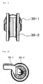
Fig. 8 is a perspective view of an idler supporting frame according to the present invention,Fig. 9 is a front view of the idler supporting frame according to the present invention, andFig. 10 is a side view of the idler supporting frame according to the present invention. - As shown in
Figs. 8 to 10 , the idler frame 30-1 is provided to support the idler 30-2 so that the idler 30-2 and the front roller can be moved together and thus they are moved at the same time. - The idler 30-2 functions to directly support a caterpillar track. The idler 30-2 is supported by the idler frame 30-1 in which the idler 30-2 is rotatably installed.
-
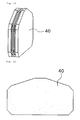
Fig. 11 is a perspective view of a buffer member according to the present invention,Fig. 12 is a front view of the buffer member according to the present invention, andFig. 13 is a side view of the buffer member according to the present invention. - As shown in
Figs. 11 to 13 , thebuffer member 40 is applied between the idler frame 30-1 for supporting the idler 30-2 and the roller frame 20-1 for supporting the front roller 20-2 so as to deal with the external shock. Thebuffer member 40 may be formed of a synthetic material such as rubber, or may be formed to include a fluid like gas therein. -
Fig. 14 is an assembling view of the apparatus for contrblling the tension of the track, in which only an idler is moved, according to the present invention. - As shown in
Fig. 14 , even in a structure which controls the tension of the track by moving only the idler frame 30-1 including the idler 30-2 without the front roller 20-2, thebuffer member 40 is applied so as to prevent the damage of thetension controlling cylinder 50, thereby increasing the durability and thus providing the comfortable ride and the enhanced operation efficiency. - According to the present invention, since the idler and the roller are moved at the same time when controlling the tension of the track, it is possible to prevent a track wheel from being separated and also to support the weight of the equipment more safely.
- Further, since the buffer member for absorbing the shock is disposed between the idler supporting frame and the roller supporting frame, it is possible to prevent the damage of the idler and the tension controlling cylinder due to the relatively large external shock generated in a moment and also to improve the durability and further to deal with the relatively small external shock and vibration so as to provide a comfortable ride to the operator, thereby enhancing the operation efficiency.
| 10: track frame | 20-1: roller frame |
| 20-2: front roller | 30-1: idler frame |
| 30-2: idler | 40: buffer member |
| 50: tension controlling cylinder | |
| 60: rear roller |
Claims (2)
- An apparatus for controlling tension of a track, comprising:a track frame (10) with an idler (30-2), a front roller (20-2), and a rear roller (60);an idler frame (30-1) in which the idler (30-2) is fixed;a roller frame (20-1) in which the front roller (20-2) is fixed; anda buffer member (40) which is disposed between the idler frame (30-1) and the roller frame (20-1) so as to deal with external shock,characterized in thatthe track frame (10) comprises a tension controlling cylinder (50),the roller frame (20-1) is assembled in the track frame (10), the buffer member (40) is firtsly inserted into the roller frame (20-1) and then the idler frame (30-1) is inserted therein, , andthe roller frame (20-1) is adapted to be moved horizontally by the tension controlling cylinder (50) of the track frame (10), and thus the roller frame (20-1) and the idler frame (30-1) are horizontally moved together at the same time so that the apparatus can control tension of a track, so as to minimize space between idler and the front roller and thus to prevent the track from being separated.
- The apparatus of claim 1, wherein the buffer member (40) is formed of a synthetic material including rubber, and a fluid or gas is provided in the buffer member (40) so that its shape can be changed.
Applications Claiming Priority (1)
| Application Number | Priority Date | Filing Date | Title |
|---|---|---|---|
| PCT/KR2009/003061 WO2010143755A1 (en) | 2009-06-08 | 2009-06-08 | Apparatus for controlling tension of track |
Publications (3)
| Publication Number | Publication Date |
|---|---|
| EP2441652A1 EP2441652A1 (en) | 2012-04-18 |
| EP2441652A4 EP2441652A4 (en) | 2012-10-24 |
| EP2441652B1 true EP2441652B1 (en) | 2014-04-23 |
Family
ID=43309001
Family Applications (1)
| Application Number | Title | Priority Date | Filing Date |
|---|---|---|---|
| EP09845849.0A Not-in-force EP2441652B1 (en) | 2009-06-08 | 2009-06-08 | Apparatus for controlling tension of track |
Country Status (6)
| Country | Link |
|---|---|
| US (1) | US8733850B2 (en) |
| EP (1) | EP2441652B1 (en) |
| JP (1) | JP5376549B2 (en) |
| KR (1) | KR101302905B1 (en) |
| CN (1) | CN102458970B (en) |
| WO (1) | WO2010143755A1 (en) |
Cited By (1)
| Publication number | Priority date | Publication date | Assignee | Title |
|---|---|---|---|---|
| US12060122B2 (en) | 2021-09-21 | 2024-08-13 | Soucy International Inc. | Modular frame, track frame having a modular frame, vehicle having track systems, track system kit, tensioner and track system having a tensioner |
Families Citing this family (9)
| Publication number | Priority date | Publication date | Assignee | Title |
|---|---|---|---|---|
| US20140001825A1 (en) * | 2012-06-29 | 2014-01-02 | Caterpillar Inc. | Track idler |
| US20140001828A1 (en) * | 2012-06-29 | 2014-01-02 | Caterpillar Inc. | Undercarriage guiding assembly |
| CN104321243A (en) * | 2012-07-30 | 2015-01-28 | 凯斯纽荷兰(中国)管理有限公司 | Undercarriage system for a tracked work vehicle |
| EP3002181A1 (en) * | 2014-10-03 | 2016-04-06 | Caterpillar, Inc. | Impact absorption device |
| JP6440594B2 (en) * | 2015-08-07 | 2018-12-19 | 株式会社クボタ | Crawler travel device |
| CN113562089B (en) * | 2015-08-07 | 2024-04-12 | 株式会社久保田 | Crawler travel device, combine harvester and harvester |
| US10526026B2 (en) | 2017-01-27 | 2020-01-07 | Barreto Manufacturing, Inc. | Carriage for a track drive vehicle |
| CN113799413A (en) * | 2021-09-08 | 2021-12-17 | 常州佰承复合材料有限公司 | A glass fiber cloth laminating car and method for controlling the tension of glass fiber cloth |
| US12286174B2 (en) | 2021-09-16 | 2025-04-29 | Caterpillar Inc. | Roller mounting and roller block assemblies for ground-engaging track system |
Family Cites Families (16)
| Publication number | Priority date | Publication date | Assignee | Title |
|---|---|---|---|---|
| US2467947A (en) * | 1945-05-22 | 1949-04-19 | Goodrich Co B F | Traction apparatus |
| US3774708A (en) * | 1971-12-27 | 1973-11-27 | Caterpillar Tractor Co | Triangular track resilient bogie suspension |
| US3841424A (en) * | 1971-12-27 | 1974-10-15 | Caterpillar Tractor Co | Triangular track resilient bogie suspension |
| US3826325A (en) * | 1972-08-22 | 1974-07-30 | Caterpillar Tractor Co | Track suspension assembly |
| GB1579048A (en) | 1977-04-07 | 1980-11-12 | Caterpillar Tractor Co | Resilient support pad |
| US4230378A (en) * | 1977-04-07 | 1980-10-28 | Caterpillar Tractor Co. | Resilient support pad for crawler type vehicles |
| WO1982000810A1 (en) * | 1980-08-29 | 1982-03-18 | Livesay R | Single roller-idler assembly for crawley undercarriage |
| BR8009129A (en) | 1980-11-19 | 1983-03-01 | Caterpillar Tractor Co | ROLLER RETREAD DEVICE - INTERMEDIATE WHEEL |
| DE3404517A1 (en) | 1984-02-09 | 1985-08-14 | Karlheinz 5800 Hagen Menkhoff | Elastomer chain tensioner for tracked vehicles |
| JPH08175442A (en) * | 1994-12-27 | 1996-07-09 | Komatsu Ltd | Crawler type vehicle running device |
| ITMI20021599A1 (en) * | 2002-07-19 | 2004-01-19 | Berco Spa | TRACK TENSIONER DEVICE FOR TRACKED VEHICLES |
| JP2004314938A (en) | 2003-03-31 | 2004-11-11 | Komatsu Ltd | Track tension adjustment device |
| US7025429B2 (en) * | 2004-02-10 | 2006-04-11 | Komatsu Ltd. | Drive assembly for a track-type vehicle |
| JP4473081B2 (en) | 2004-09-21 | 2010-06-02 | 日立建機株式会社 | Tracked vehicle |
| KR100787367B1 (en) | 2006-09-20 | 2007-12-18 | 동일고무벨트주식회사 | Heavy Duty Track Tensioner |
| DE502007003479D1 (en) * | 2007-10-18 | 2010-05-27 | Joseph Voegele Ag | crawler track |
-
2009
- 2009-06-08 EP EP09845849.0A patent/EP2441652B1/en not_active Not-in-force
- 2009-06-08 KR KR1020117020941A patent/KR101302905B1/en not_active Expired - Fee Related
- 2009-06-08 WO PCT/KR2009/003061 patent/WO2010143755A1/en not_active Ceased
- 2009-06-08 JP JP2012513841A patent/JP5376549B2/en not_active Expired - Fee Related
- 2009-06-08 US US13/376,255 patent/US8733850B2/en not_active Expired - Fee Related
- 2009-06-08 CN CN200980159747.9A patent/CN102458970B/en not_active Expired - Fee Related
Cited By (3)
| Publication number | Priority date | Publication date | Assignee | Title |
|---|---|---|---|---|
| US12060122B2 (en) | 2021-09-21 | 2024-08-13 | Soucy International Inc. | Modular frame, track frame having a modular frame, vehicle having track systems, track system kit, tensioner and track system having a tensioner |
| US12103610B2 (en) | 2021-09-21 | 2024-10-01 | Soucy International Inc. | Modular frame, track frame having a modular frame, vehicle having track systems, track system kit, tensioner and track system having a tensioner |
| US12509169B2 (en) | 2021-09-21 | 2025-12-30 | Soucy International Inc. | Modular frame, track frame having a modular frame, vehicle having track systems, track system kit, tensioner and track system having a tensioner |
Also Published As
| Publication number | Publication date |
|---|---|
| KR20110123259A (en) | 2011-11-14 |
| WO2010143755A1 (en) | 2010-12-16 |
| EP2441652A4 (en) | 2012-10-24 |
| CN102458970A (en) | 2012-05-16 |
| US20120080937A1 (en) | 2012-04-05 |
| CN102458970B (en) | 2014-04-23 |
| US8733850B2 (en) | 2014-05-27 |
| JP5376549B2 (en) | 2013-12-25 |
| EP2441652A1 (en) | 2012-04-18 |
| JP2012528761A (en) | 2012-11-15 |
| KR101302905B1 (en) | 2013-09-06 |
Similar Documents
| Publication | Publication Date | Title |
|---|---|---|
| US8733850B2 (en) | Apparatus for controlling tension of track | |
| CN102390445B (en) | High-mounted crawler track walking system with suspended shock-absorbing device | |
| US7231993B2 (en) | Drive track support with vibration isolation | |
| US7717201B2 (en) | Undercarriage having shock absorption function | |
| KR20120064515A (en) | Undercarriage with a structure for buffering tension of rubber crawler | |
| US20050077784A1 (en) | Vehicle track with idler and roller suspension | |
| JP7721280B2 (en) | freight vehicle with driver's cab | |
| JP3625909B2 (en) | Anti-vibration mechanism for crawler type traveling device | |
| KR102491801B1 (en) | Suspension system for electric four-wheeled vehicles | |
| JP2020172207A (en) | Crawler driving vehicle | |
| US20170334490A1 (en) | Tractor | |
| CN103921115A (en) | Delivery device of door and cover assembly of welding adjusting line | |
| CN112895829B (en) | A drive wheel independent shock-absorbing structure for AGV drive assembly | |
| CN115123411A (en) | Wheel-track vehicle chassis and wheel-track vehicle | |
| JP3234548B2 (en) | Crawler type traveling device | |
| KR0128511Y1 (en) | A foot cushion device of fork lift truck | |
| CN211236812U (en) | Portable case with shock-absorbing function | |
| KR100828762B1 (en) | Leaf Spring Suspension in Front Two-Axis Vehicles | |
| JP2723755B2 (en) | Work vehicle frame structure | |
| WO2015038181A1 (en) | Undercarriage for a power machine | |
| US11008056B2 (en) | Isolation system from noise and vibrations for a work vehicle | |
| JP2024164585A (en) | Conveyor | |
| KR100836392B1 (en) | Shock absorber installation structure of rear suspension | |
| KR20090041584A (en) | 4-side frame undercarriage for heavy construction equipment | |
| JP4998273B2 (en) | Vehicle suspension system |
Legal Events
| Date | Code | Title | Description |
|---|---|---|---|
| PUAI | Public reference made under article 153(3) epc to a published international application that has entered the european phase |
Free format text: ORIGINAL CODE: 0009012 |
|
| 17P | Request for examination filed |
Effective date: 20111207 |
|
| AK | Designated contracting states |
Kind code of ref document: A1 Designated state(s): AT BE BG CH CY CZ DE DK EE ES FI FR GB GR HR HU IE IS IT LI LT LU LV MC MK MT NL NO PL PT RO SE SI SK TR |
|
| DAX | Request for extension of the european patent (deleted) | ||
| A4 | Supplementary search report drawn up and despatched |
Effective date: 20120921 |
|
| RIC1 | Information provided on ipc code assigned before grant |
Ipc: F16H 7/08 20060101ALI20120917BHEP Ipc: B62D 55/30 20060101AFI20120917BHEP Ipc: B62D 55/08 20060101ALI20120917BHEP |
|
| GRAP | Despatch of communication of intention to grant a patent |
Free format text: ORIGINAL CODE: EPIDOSNIGR1 |
|
| INTG | Intention to grant announced |
Effective date: 20130711 |
|
| GRAS | Grant fee paid |
Free format text: ORIGINAL CODE: EPIDOSNIGR3 |
|
| GRAA | (expected) grant |
Free format text: ORIGINAL CODE: 0009210 |
|
| RAP1 | Party data changed (applicant data changed or rights of an application transferred) |
Owner name: DRB HOLDING CO., LTD. |
|
| AK | Designated contracting states |
Kind code of ref document: B1 Designated state(s): AT BE BG CH CY CZ DE DK EE ES FI FR GB GR HR HU IE IS IT LI LT LU LV MC MK MT NL NO PL PT RO SE SI SK TR |
|
| REG | Reference to a national code |
Ref country code: GB Ref legal event code: FG4D |
|
| REG | Reference to a national code |
Ref country code: CH Ref legal event code: EP |
|
| REG | Reference to a national code |
Ref country code: AT Ref legal event code: REF Ref document number: 663652 Country of ref document: AT Kind code of ref document: T Effective date: 20140515 |
|
| REG | Reference to a national code |
Ref country code: IE Ref legal event code: FG4D |
|
| REG | Reference to a national code |
Ref country code: DE Ref legal event code: R096 Ref document number: 602009023588 Country of ref document: DE Effective date: 20140605 |
|
| REG | Reference to a national code |
Ref country code: AT Ref legal event code: MK05 Ref document number: 663652 Country of ref document: AT Kind code of ref document: T Effective date: 20140423 |
|
| REG | Reference to a national code |
Ref country code: NL Ref legal event code: VDEP Effective date: 20140423 |
|
| REG | Reference to a national code |
Ref country code: LT Ref legal event code: MG4D |
|
| PG25 | Lapsed in a contracting state [announced via postgrant information from national office to epo] |
Ref country code: NL Free format text: LAPSE BECAUSE OF FAILURE TO SUBMIT A TRANSLATION OF THE DESCRIPTION OR TO PAY THE FEE WITHIN THE PRESCRIBED TIME-LIMIT Effective date: 20140423 Ref country code: FI Free format text: LAPSE BECAUSE OF FAILURE TO SUBMIT A TRANSLATION OF THE DESCRIPTION OR TO PAY THE FEE WITHIN THE PRESCRIBED TIME-LIMIT Effective date: 20140423 Ref country code: GR Free format text: LAPSE BECAUSE OF FAILURE TO SUBMIT A TRANSLATION OF THE DESCRIPTION OR TO PAY THE FEE WITHIN THE PRESCRIBED TIME-LIMIT Effective date: 20140724 Ref country code: IS Free format text: LAPSE BECAUSE OF FAILURE TO SUBMIT A TRANSLATION OF THE DESCRIPTION OR TO PAY THE FEE WITHIN THE PRESCRIBED TIME-LIMIT Effective date: 20140823 Ref country code: NO Free format text: LAPSE BECAUSE OF FAILURE TO SUBMIT A TRANSLATION OF THE DESCRIPTION OR TO PAY THE FEE WITHIN THE PRESCRIBED TIME-LIMIT Effective date: 20140723 Ref country code: BG Free format text: LAPSE BECAUSE OF FAILURE TO SUBMIT A TRANSLATION OF THE DESCRIPTION OR TO PAY THE FEE WITHIN THE PRESCRIBED TIME-LIMIT Effective date: 20140723 Ref country code: LT Free format text: LAPSE BECAUSE OF FAILURE TO SUBMIT A TRANSLATION OF THE DESCRIPTION OR TO PAY THE FEE WITHIN THE PRESCRIBED TIME-LIMIT Effective date: 20140423 Ref country code: CY Free format text: LAPSE BECAUSE OF FAILURE TO SUBMIT A TRANSLATION OF THE DESCRIPTION OR TO PAY THE FEE WITHIN THE PRESCRIBED TIME-LIMIT Effective date: 20140423 |
|
| PG25 | Lapsed in a contracting state [announced via postgrant information from national office to epo] |
Ref country code: SE Free format text: LAPSE BECAUSE OF FAILURE TO SUBMIT A TRANSLATION OF THE DESCRIPTION OR TO PAY THE FEE WITHIN THE PRESCRIBED TIME-LIMIT Effective date: 20140423 Ref country code: LV Free format text: LAPSE BECAUSE OF FAILURE TO SUBMIT A TRANSLATION OF THE DESCRIPTION OR TO PAY THE FEE WITHIN THE PRESCRIBED TIME-LIMIT Effective date: 20140423 Ref country code: HR Free format text: LAPSE BECAUSE OF FAILURE TO SUBMIT A TRANSLATION OF THE DESCRIPTION OR TO PAY THE FEE WITHIN THE PRESCRIBED TIME-LIMIT Effective date: 20140423 Ref country code: ES Free format text: LAPSE BECAUSE OF FAILURE TO SUBMIT A TRANSLATION OF THE DESCRIPTION OR TO PAY THE FEE WITHIN THE PRESCRIBED TIME-LIMIT Effective date: 20140423 Ref country code: PL Free format text: LAPSE BECAUSE OF FAILURE TO SUBMIT A TRANSLATION OF THE DESCRIPTION OR TO PAY THE FEE WITHIN THE PRESCRIBED TIME-LIMIT Effective date: 20140423 Ref country code: AT Free format text: LAPSE BECAUSE OF FAILURE TO SUBMIT A TRANSLATION OF THE DESCRIPTION OR TO PAY THE FEE WITHIN THE PRESCRIBED TIME-LIMIT Effective date: 20140423 |
|
| PG25 | Lapsed in a contracting state [announced via postgrant information from national office to epo] |
Ref country code: PT Free format text: LAPSE BECAUSE OF FAILURE TO SUBMIT A TRANSLATION OF THE DESCRIPTION OR TO PAY THE FEE WITHIN THE PRESCRIBED TIME-LIMIT Effective date: 20140825 |
|
| REG | Reference to a national code |
Ref country code: DE Ref legal event code: R097 Ref document number: 602009023588 Country of ref document: DE |
|
| PG25 | Lapsed in a contracting state [announced via postgrant information from national office to epo] |
Ref country code: MC Free format text: LAPSE BECAUSE OF FAILURE TO SUBMIT A TRANSLATION OF THE DESCRIPTION OR TO PAY THE FEE WITHIN THE PRESCRIBED TIME-LIMIT Effective date: 20140423 Ref country code: BE Free format text: LAPSE BECAUSE OF FAILURE TO SUBMIT A TRANSLATION OF THE DESCRIPTION OR TO PAY THE FEE WITHIN THE PRESCRIBED TIME-LIMIT Effective date: 20140423 Ref country code: DK Free format text: LAPSE BECAUSE OF FAILURE TO SUBMIT A TRANSLATION OF THE DESCRIPTION OR TO PAY THE FEE WITHIN THE PRESCRIBED TIME-LIMIT Effective date: 20140423 Ref country code: EE Free format text: LAPSE BECAUSE OF FAILURE TO SUBMIT A TRANSLATION OF THE DESCRIPTION OR TO PAY THE FEE WITHIN THE PRESCRIBED TIME-LIMIT Effective date: 20140423 Ref country code: CZ Free format text: LAPSE BECAUSE OF FAILURE TO SUBMIT A TRANSLATION OF THE DESCRIPTION OR TO PAY THE FEE WITHIN THE PRESCRIBED TIME-LIMIT Effective date: 20140423 Ref country code: LU Free format text: LAPSE BECAUSE OF FAILURE TO SUBMIT A TRANSLATION OF THE DESCRIPTION OR TO PAY THE FEE WITHIN THE PRESCRIBED TIME-LIMIT Effective date: 20140608 Ref country code: SK Free format text: LAPSE BECAUSE OF FAILURE TO SUBMIT A TRANSLATION OF THE DESCRIPTION OR TO PAY THE FEE WITHIN THE PRESCRIBED TIME-LIMIT Effective date: 20140423 Ref country code: RO Free format text: LAPSE BECAUSE OF FAILURE TO SUBMIT A TRANSLATION OF THE DESCRIPTION OR TO PAY THE FEE WITHIN THE PRESCRIBED TIME-LIMIT Effective date: 20140423 |
|
| REG | Reference to a national code |
Ref country code: CH Ref legal event code: PL |
|
| PLBE | No opposition filed within time limit |
Free format text: ORIGINAL CODE: 0009261 |
|
| STAA | Information on the status of an ep patent application or granted ep patent |
Free format text: STATUS: NO OPPOSITION FILED WITHIN TIME LIMIT |
|
| REG | Reference to a national code |
Ref country code: IE Ref legal event code: MM4A |
|
| 26N | No opposition filed |
Effective date: 20150126 |
|
| PG25 | Lapsed in a contracting state [announced via postgrant information from national office to epo] |
Ref country code: LI Free format text: LAPSE BECAUSE OF NON-PAYMENT OF DUE FEES Effective date: 20140630 Ref country code: IE Free format text: LAPSE BECAUSE OF NON-PAYMENT OF DUE FEES Effective date: 20140608 Ref country code: CH Free format text: LAPSE BECAUSE OF NON-PAYMENT OF DUE FEES Effective date: 20140630 |
|
| REG | Reference to a national code |
Ref country code: DE Ref legal event code: R097 Ref document number: 602009023588 Country of ref document: DE Effective date: 20150126 |
|
| PG25 | Lapsed in a contracting state [announced via postgrant information from national office to epo] |
Ref country code: SI Free format text: LAPSE BECAUSE OF FAILURE TO SUBMIT A TRANSLATION OF THE DESCRIPTION OR TO PAY THE FEE WITHIN THE PRESCRIBED TIME-LIMIT Effective date: 20140423 |
|
| PG25 | Lapsed in a contracting state [announced via postgrant information from national office to epo] |
Ref country code: MT Free format text: LAPSE BECAUSE OF FAILURE TO SUBMIT A TRANSLATION OF THE DESCRIPTION OR TO PAY THE FEE WITHIN THE PRESCRIBED TIME-LIMIT Effective date: 20140423 |
|
| REG | Reference to a national code |
Ref country code: FR Ref legal event code: PLFP Year of fee payment: 8 |
|
| PG25 | Lapsed in a contracting state [announced via postgrant information from national office to epo] |
Ref country code: TR Free format text: LAPSE BECAUSE OF FAILURE TO SUBMIT A TRANSLATION OF THE DESCRIPTION OR TO PAY THE FEE WITHIN THE PRESCRIBED TIME-LIMIT Effective date: 20140423 Ref country code: HU Free format text: LAPSE BECAUSE OF FAILURE TO SUBMIT A TRANSLATION OF THE DESCRIPTION OR TO PAY THE FEE WITHIN THE PRESCRIBED TIME-LIMIT; INVALID AB INITIO Effective date: 20090608 |
|
| REG | Reference to a national code |
Ref country code: FR Ref legal event code: PLFP Year of fee payment: 9 |
|
| REG | Reference to a national code |
Ref country code: FR Ref legal event code: PLFP Year of fee payment: 10 |
|
| PG25 | Lapsed in a contracting state [announced via postgrant information from national office to epo] |
Ref country code: MK Free format text: LAPSE BECAUSE OF FAILURE TO SUBMIT A TRANSLATION OF THE DESCRIPTION OR TO PAY THE FEE WITHIN THE PRESCRIBED TIME-LIMIT Effective date: 20140423 |
|
| PGFP | Annual fee paid to national office [announced via postgrant information from national office to epo] |
Ref country code: FR Payment date: 20180622 Year of fee payment: 10 |
|
| PGFP | Annual fee paid to national office [announced via postgrant information from national office to epo] |
Ref country code: IT Payment date: 20180629 Year of fee payment: 10 Ref country code: DE Payment date: 20180627 Year of fee payment: 10 Ref country code: GB Payment date: 20180622 Year of fee payment: 10 |
|
| REG | Reference to a national code |
Ref country code: DE Ref legal event code: R119 Ref document number: 602009023588 Country of ref document: DE |
|
| GBPC | Gb: european patent ceased through non-payment of renewal fee |
Effective date: 20190608 |
|
| PG25 | Lapsed in a contracting state [announced via postgrant information from national office to epo] |
Ref country code: GB Free format text: LAPSE BECAUSE OF NON-PAYMENT OF DUE FEES Effective date: 20190608 Ref country code: DE Free format text: LAPSE BECAUSE OF NON-PAYMENT OF DUE FEES Effective date: 20200101 Ref country code: IT Free format text: LAPSE BECAUSE OF NON-PAYMENT OF DUE FEES Effective date: 20190608 |
|
| PG25 | Lapsed in a contracting state [announced via postgrant information from national office to epo] |
Ref country code: FR Free format text: LAPSE BECAUSE OF NON-PAYMENT OF DUE FEES Effective date: 20190630 |