EP2441651A2 - Tractor weight arrangement - Google Patents
Tractor weight arrangement Download PDFInfo
- Publication number
- EP2441651A2 EP2441651A2 EP11183766A EP11183766A EP2441651A2 EP 2441651 A2 EP2441651 A2 EP 2441651A2 EP 11183766 A EP11183766 A EP 11183766A EP 11183766 A EP11183766 A EP 11183766A EP 2441651 A2 EP2441651 A2 EP 2441651A2
- Authority
- EP
- European Patent Office
- Prior art keywords
- weight
- weight member
- chassis
- tractor
- raising
- Prior art date
- Legal status (The legal status is an assumption and is not a legal conclusion. Google has not performed a legal analysis and makes no representation as to the accuracy of the status listed.)
- Withdrawn
Links
- 230000015572 biosynthetic process Effects 0.000 claims description 14
- 238000005755 formation reaction Methods 0.000 claims description 14
- 239000000725 suspension Substances 0.000 claims description 10
- 238000000034 method Methods 0.000 claims description 5
- 230000000717 retained effect Effects 0.000 claims description 3
- 210000001015 abdomen Anatomy 0.000 abstract description 8
- 238000010276 construction Methods 0.000 description 1
- 210000001364 upper extremity Anatomy 0.000 description 1
Images




Classifications
-
- B—PERFORMING OPERATIONS; TRANSPORTING
- B01—PHYSICAL OR CHEMICAL PROCESSES OR APPARATUS IN GENERAL
- B01D—SEPARATION
- B01D1/00—Evaporating
- B01D1/0011—Heating features
- B01D1/0041—Use of fluids
- B01D1/0047—Use of fluids in a closed circuit
-
- B—PERFORMING OPERATIONS; TRANSPORTING
- B01—PHYSICAL OR CHEMICAL PROCESSES OR APPARATUS IN GENERAL
- B01D—SEPARATION
- B01D17/00—Separation of liquids, not provided for elsewhere, e.g. by thermal diffusion
- B01D17/02—Separation of non-miscible liquids
- B01D17/04—Breaking emulsions
- B01D17/042—Breaking emulsions by changing the temperature
-
- C—CHEMISTRY; METALLURGY
- C10—PETROLEUM, GAS OR COKE INDUSTRIES; TECHNICAL GASES CONTAINING CARBON MONOXIDE; FUELS; LUBRICANTS; PEAT
- C10G—CRACKING HYDROCARBON OILS; PRODUCTION OF LIQUID HYDROCARBON MIXTURES, e.g. BY DESTRUCTIVE HYDROGENATION, OLIGOMERISATION, POLYMERISATION; RECOVERY OF HYDROCARBON OILS FROM OIL-SHALE, OIL-SAND, OR GASES; REFINING MIXTURES MAINLY CONSISTING OF HYDROCARBONS; REFORMING OF NAPHTHA; MINERAL WAXES
- C10G9/00—Thermal non-catalytic cracking, in the absence of hydrogen, of hydrocarbon oils
- C10G9/14—Thermal non-catalytic cracking, in the absence of hydrogen, of hydrocarbon oils in pipes or coils with or without auxiliary means, e.g. digesters, soaking drums, expansion means
- C10G9/18—Apparatus
- C10G9/20—Tube furnaces
Definitions
- This invention relates to a weight arrangement for use on an agricultural or industrial tractor.
- a tractor weight arrangement comprising a weight member designed to be mounted under a tractor chassis, and attachment means for securing the weight member in its operational position under the chassis, the arrangement being characterised in that the weight member has front raising means for use in raising the front of the weight to it operation position under the chassis and separate rear raising means for use in raising the rear of the weight to is operational position under the chassis, and in that the weight is provided with detachable support means for supporting the weight above the ground so that the front and rear raising means can be engaged to allow weight to be raised to its operational position under the chassis.
- Such an arrangement can be easily attached and detached from the tractor without the use of additional lifting equipment when use of the weight is not required.
- the weight may be provided with separate detachable support means at the front and rear end of the weight member.
- the detachable support means may comprises a first pair of detachable support legs located at the front end of the weight member and a second pair of detachable support legs located at the rear end of the weight member.
- the front raising means may comprise a hook for engagement with a formation provided on the front portion of the tractor chassis.
- the rear raising means may comprise formations on the rear detachable support means for engagement by rear draft links of the tractor to allow the rear of the weight member to be raised to its operational position by raising the draft links.
- the front and rear detachable support means may be received in recesses in the weight member and may be held therein by pin which are retained in position by a screw retainer.
- the tractor has a front suspension the height of which can be raised and lowered by the tractor operator, the front raising means being engageable with a cooperating formation on the chassis by the operator lowering the front suspension to engage the front raising means with a cooperating formation on the chassis and then raising the suspension to lift the front of the weight member into its operational position.
- the attachment means comprise bolts which extend through holes in the weight member to attach the weight member to the underside of the chassis.
- the weight member may include a moveable weight section which can be moved fore and aft relative to the remainder of the weight member to adjust the ballasting of the tractor.
- the moveable weight section may be slidable in tracks formed in the remainder of the weight member.
- An actuating means may be provided to move the moveable weight section relative to the remainder of the weight member.
- this actuating means may comprise a hydraulic ram or an electric motor driven system for moving the moveable weight section.
- the weight member may be provided with additional attachment points to which additional weights or other components can be mounted.
- the invention also provides a method of mounting a tractor weight member on the underside of a tractor chassis, said method comprising lowering a front axle of the tractor to engage front raising means on the weight member with a cooperating formation on the front of the chassis, raising the suspension to raise the front of the weight member into its operational position against the underside of the chassis, engaging rear draft links of the tractor with rear raising means on the weight member, raising the draft links to raise the rear of the weight member into its operational position against the underside of the chassis, and securing the weight member to the underside of the chassis using attachment means.
- the weight member may be initially supported above the ground on detachable support means which are disconnected from the weight member after the weight member has been secured to the chassis.
- a tractor belly weight arrangement 10 comprises a main weight member 11 which can be machined from a thick plate member or can be of a cast construction.
- the weight member 11 has at its front end a front raising means in the form of a hook 12 which can be engaged with a co-operating formation provided on a front portion 13 of the tractor chassis 14.
- the weight member 11 is provided with detachable front support means 15 in the form of a pair of legs 16 which, as shown in Figures 8a to 8c are received in recesses 17 formed in the front portion of weight member 11.
- the legs 16 are retained in their recesses by pins 18 which extend through bores 16a and 11a in the legs 16 and weight member 11 respectively.
- the pins 18 are held in position by screw fastenings 19 which extend through plates 20 attached to the ends of pins 18.
- a rear support means 21 is provided in the form of a further pair of angled legs 22 which are again received in recesses 23 provided in the rear of weight member 11 and held in these recesses by pins 24 which extend through bores 22a and 11 b in the legs 22 and weight member 11 respectively and are again held in position by screw fasteners 25 which extend through plates 26 secured to the pins 24.
- the rear of the weight member I 1 can be raised to its operational position beneath the chassis 14 by engaging the hooks 28 of the rear draft links 29 of the tractor with rear raising means 30 provided in the form of a cross bar 31 secured between the angled rear legs 22. The draft links are then raised to raise the rear of the weight member 11 in to its operational position.
- the front support legs 16 are released from the weight by removing the screw fasteners 19 and the pins 18 and similarly the rear support legs 22 are released by releasing the screw fastenings 25 and the associated pins 24.
- the weight is then its full operational position below the tractor.
- FIGs 1 to 6 The various stages in the attachment sequence of the weight to the tractor are shown in Figures 1 to 6 .
- the tractor is driven above the weight member 11 which is supported from the front support legs 16 and rear support legs 22.
- the front axle is then lowered so that the front raising hook 12 can be engaged with the co-operating front formation 13 on the tractor chassis. This is shown in Figure 2 .
- the front axle is then raised to its normal operating height so that the front legs 16 are now raised from the ground as shown in Figure 3 .
- weight member 11 As can be seen from Figure 9a the underside of weight member 11 is provided with attachment points 33 to which additional weights or other components can be attached.
- Figure 12 shows diagrammatically such additional weights 34 mounted below the main weight member 11.
- Figures 13, 14 and 15 show an alterative belly weight arrangement in which the main weight member 11 includes a moveable weight section 35 which has projecting flanges 35a and rollers 35b which slide in tracks 36 cut into the weight member 11. This allows the moveable weight section 35 to be slid in the fore and aft direction as indicated by arrow S in Figure 13 so that the ballasting of the tractor can be adjusted.
- the moveable weight section 35 may be provided with attachment points 37 to mount additional weights 34 similar to Figure 12 .
- the tractor may be provided with a hydraulic ram for moving the weight section 35 in direction S. Alternatively other arrangements for moving the weight section can be provided such as an electric motor which engages a chain drive arrangement.
- a further advantage of the belly weight arrangement of the present invention is that the weight connects separate parts of the tractor chassis to each other, especially the front chassis parts to rear chassis parts.
- the overall stiffness of the chassis is improved and, the load of (additional) weights or components is thereby better distributed to the complete chassis.
- the belly weight can be used to attach implements to the reinforced chassis. For example a dozer blade can be attached via the belly weight.
- the weight member 11 is not bolted to the underside of the chassis using bolts but other attachment means such as moveable hooks or latches are provided which engage cooperating formations on the chassis to maintain the operational position of the weight member.
- These hooks or latches may be operated by electric or hydraulic motors to avoid manual work by the tractor operator and may be controlled from inside the cab.
Landscapes
- Chemical & Material Sciences (AREA)
- Physics & Mathematics (AREA)
- Thermal Sciences (AREA)
- Chemical Kinetics & Catalysis (AREA)
- Oil, Petroleum & Natural Gas (AREA)
- Engineering & Computer Science (AREA)
- General Chemical & Material Sciences (AREA)
- Organic Chemistry (AREA)
- Agricultural Machines (AREA)
- Body Structure For Vehicles (AREA)
Abstract
Description
- This invention relates to a weight arrangement for use on an agricultural or industrial tractor.
- It is becoming increasingly necessary for tractors to carry large amounts of weight to counterbalance heavy and/long implements mounted on the front or rear of the tractor or to ensure that the tractor can operate without excessive slip particularly when undertaking operations in the field. This can lead to bulky additional weights which are often hung on the front of a tractor and which therefore restrict the ability of the tractor to carry front mounted equipment and can even reduce the turning circle of the tractor if a large number of weights are mounted side by side. Also such weights can be difficult to attached and detach from the tractor as they normally require the use of lifting equipment due to their large weight. This can lead to the weights being used when they are not really required. This results in inefficient operation of the tractor.
- It is an object of the present invention to provide a weight arrangement which at least reduces some of the above problems.
- Thus in accordance with the present invention there is provided a tractor weight arrangement comprising a weight member designed to be mounted under a tractor chassis, and attachment means for securing the weight member in its operational position under the chassis, the arrangement being characterised in that the weight member has front raising means for use in raising the front of the weight to it operation position under the chassis and separate rear raising means for use in raising the rear of the weight to is operational position under the chassis, and in that the weight is provided with detachable support means for supporting the weight above the ground so that the front and rear raising means can be engaged to allow weight to be raised to its operational position under the chassis.
- Such an arrangement can be easily attached and detached from the tractor without the use of additional lifting equipment when use of the weight is not required.
- The weight may be provided with separate detachable support means at the front and rear end of the weight member.
- The detachable support means may comprises a first pair of detachable support legs located at the front end of the weight member and a second pair of detachable support legs located at the rear end of the weight member.
- The front raising means may comprise a hook for engagement with a formation provided on the front portion of the tractor chassis.
- The rear raising means may comprise formations on the rear detachable support means for engagement by rear draft links of the tractor to allow the rear of the weight member to be raised to its operational position by raising the draft links.
- The front and rear detachable support means may be received in recesses in the weight member and may be held therein by pin which are retained in position by a screw retainer.
- Conveniently the tractor has a front suspension the height of which can be raised and lowered by the tractor operator, the front raising means being engageable with a cooperating formation on the chassis by the operator lowering the front suspension to engage the front raising means with a cooperating formation on the chassis and then raising the suspension to lift the front of the weight member into its operational position.
- The attachment means comprise bolts which extend through holes in the weight member to attach the weight member to the underside of the chassis.
- The weight member may include a moveable weight section which can be moved fore and aft relative to the remainder of the weight member to adjust the ballasting of the tractor.
- The moveable weight section may be slidable in tracks formed in the remainder of the weight member.
- An actuating means may be provided to move the moveable weight section relative to the remainder of the weight member. Conveniently this actuating means may comprise a hydraulic ram or an electric motor driven system for moving the moveable weight section.
- The weight member may be provided with additional attachment points to which additional weights or other components can be mounted.
- The invention also provides a method of mounting a tractor weight member on the underside of a tractor chassis, said method comprising lowering a front axle of the tractor to engage front raising means on the weight member with a cooperating formation on the front of the chassis, raising the suspension to raise the front of the weight member into its operational position against the underside of the chassis, engaging rear draft links of the tractor with rear raising means on the weight member, raising the draft links to raise the rear of the weight member into its operational position against the underside of the chassis, and securing the weight member to the underside of the chassis using attachment means.
- The weight member may be initially supported above the ground on detachable support means which are disconnected from the weight member after the weight member has been secured to the chassis.
- The present invention will now be described, by way example only, with reference to the accompanying drawings in which:-
-
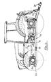
Figure 1 shows a tractor being driven over a weight arrangement in accordance with the present invention; -
Figure 2 shows the front suspension of the tractor lowered so that the front of the weight can be attached to the tractor chassis; -
Figure 3 shows the front suspension raised to raise the weight; -
Figure 4 shows the rear of the weight being attached to the tractor draft links so it can also be raised in to its operational position; -
Figure 5 shows the weight raised at the front and rear in to its operational position against the underside of the tractor chassis; -
Figure 6 shows the weight with the detachable support means at the front and rear of the weight having been removed; -
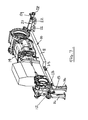
Figure 7 shows a perspective and somewhat diagrammatic view of the weight in its operational position with the front and rear support means still in position; -
Figures 8a, 8b, 8c and 8d show details of the attachment of the front and rear support means to the weight; -
Figures 9a and 9b show details of the attachment of the weight to the underside of the tractor chassis using bolts; -
Figures 10a, 10b and 10c show plan, side view and underplan view of the weight and its front and rear support means; -
Figures 11a, 11b and 11c show perspective views of the weight and its detachable support means; -
Figure 12 shows the weight in position on the tractor with additional weights attached beneath the belly weight, and -
Figures 13,14 and15 show perspective and sectional views of an alternative belly weight arrangement which has a moveable weight section which can be slid in a fore and aft sense in order to adjust the ballasting of the tractor. - Referring to the drawings, a tractor
belly weight arrangement 10 comprises amain weight member 11 which can be machined from a thick plate member or can be of a cast construction. Theweight member 11 has at its front end a front raising means in the form of ahook 12 which can be engaged with a co-operating formation provided on afront portion 13 of thetractor chassis 14. Theweight member 11 is provided with detachable front support means 15 in the form of a pair oflegs 16 which, as shown inFigures 8a to 8c are received inrecesses 17 formed in the front portion ofweight member 11. Thelegs 16 are retained in their recesses by pins 18 which extend through bores 16a and 11a in thelegs 16 andweight member 11 respectively. The pins 18 are held in position byscrew fastenings 19 which extend throughplates 20 attached to the ends of pins 18. - At the rear of the weight member 11 a rear support means 21 is provided in the form of a further pair of
angled legs 22 which are again received inrecesses 23 provided in the rear ofweight member 11 and held in these recesses bypins 24 which extend throughbores 22a and 11 b in thelegs 22 andweight member 11 respectively and are again held in position byscrew fasteners 25 which extend throughplates 26 secured to thepins 24. The rear of the weight member I 1 can be raised to its operational position beneath thechassis 14 by engaging thehooks 28 of therear draft links 29 of the tractor withrear raising means 30 provided in the form of across bar 31 secured between the angledrear legs 22. The draft links are then raised to raise the rear of theweight member 11 in to its operational position. Once the front and rear of the weight member have been raised in to their operational positions in contact with the underside of thetractor chassis 14 the weight is secured to the chassis bybolts 32 which extend through theweight member 11 into thechassis 14. - After the weight has been secured to the chassis by
bolts 32 thefront support legs 16 are released from the weight by removing thescrew fasteners 19 and the pins 18 and similarly therear support legs 22 are released by releasing thescrew fastenings 25 and the associatedpins 24. The weight is then its full operational position below the tractor. - The various stages in the attachment sequence of the weight to the tractor are shown in
Figures 1 to 6 . InFigure 1 the tractor is driven above theweight member 11 which is supported from thefront support legs 16 andrear support legs 22. The front axle is then lowered so that the front raisinghook 12 can be engaged with theco-operating front formation 13 on the tractor chassis. This is shown inFigure 2 . The front axle is then raised to its normal operating height so that thefront legs 16 are now raised from the ground as shown inFigure 3 . - After lowering the
draft links 29 thehooks 28 of thedraft links 29 of the tractor are then engaged with the rear raising means in the form ofcrossbar 31 as shown inFigure 4 and the draft links are then raised to move the rear of the weight to its operational position in contact with the underside of thechassis 14 as shown inFigure 5 . The weight is then bolted to the underside of thechassis using bolts 32 and the front andrear support legs pins 18 and 14. Theweight member 11 then occupies its operational position show inFigure 6 in which it is in full contact with the underside of the tractor chassis. - As can be seen from
Figure 9a the underside ofweight member 11 is provided withattachment points 33 to which additional weights or other components can be attached.Figure 12 shows diagrammatically suchadditional weights 34 mounted below themain weight member 11. -
Figures 13, 14 and15 show an alterative belly weight arrangement in which themain weight member 11 includes amoveable weight section 35 which has projectingflanges 35a androllers 35b which slide intracks 36 cut into theweight member 11. This allows themoveable weight section 35 to be slid in the fore and aft direction as indicated by arrow S inFigure 13 so that the ballasting of the tractor can be adjusted. Themoveable weight section 35 may be provided withattachment points 37 to mountadditional weights 34 similar toFigure 12 . The tractor may be provided with a hydraulic ram for moving theweight section 35 in direction S. Alternatively other arrangements for moving the weight section can be provided such as an electric motor which engages a chain drive arrangement. - A further advantage of the belly weight arrangement of the present invention is that the weight connects separate parts of the tractor chassis to each other, especially the front chassis parts to rear chassis parts. Thus the overall stiffness of the chassis is improved and, the load of (additional) weights or components is thereby better distributed to the complete chassis. This contrasts with, for example, attaching weights etc. to front linkage when only the front part of the chassis can to bear the load. In addition the belly weight can be used to attach implements to the reinforced chassis. For example a dozer blade can be attached via the belly weight.
- In a further embodiment (not shown) the
weight member 11 is not bolted to the underside of the chassis using bolts but other attachment means such as moveable hooks or latches are provided which engage cooperating formations on the chassis to maintain the operational position of the weight member. These hooks or latches may be operated by electric or hydraulic motors to avoid manual work by the tractor operator and may be controlled from inside the cab.
Claims (15)
- A tractor weight arrangement comprising a weight member designed to be mounted under a tractor chassis, and attachment means for securing the weight member in its operational position under the chassis, the arrangement being characterised in that the weight member has front raising means for use in raising the front of the weight to it operation position under the chassis and separate rear raising means for use in raising the rear of the weight to is operational position under the chassis, and in that the weight is provided with detachable support means for supporting the weight above the ground so that the front and rear raising means can be engaged to allow weight to be raised to its operational position under the chassis.
- A weight arrangement according to claim 1 characterised in that separate detachable support means are provided at the front end and rear end of the weight member.
- A weight arrangement according to claim 2 characterised in that the detachable support means comprises a first pair of detachable support legs located at the front end of the weight member and a second pair of detachable support legs located at the rear end of the weight member.
- A weight arrangement according to any one of claims 1 to 3 characterised in the front raising means comprises a hook for engagement with a formation provided on the front portion of the tractor chassis and/or the rear the rear raising means comprises formations on the rear detachable support means for engagement by rear draft links of the tractor to allow the rear of the weight member to be raised to its operational position by raising the draft links.
- A weight arrangement according to any one of claims 2 to 4 characterised in that the front and rear detachable support means are received in recesses in the weight member and are each held therein by pin which are retained in position by a screw retainer.
- A weight arrangement according to any one of claims I to 5 characterised in that the tractor has a front suspension the height of which can be raised and lowered by the tractor operator, the front raising means being engageable with a cooperating formation on the chassis by the operator lowering the front suspension to engage the front raising means with a cooperating formation on the chassis and then raising the suspension to lift the front of the weight member into its operational position.
- A weight arrangement according to any one of claims I to 6 characterised in that the attachment means comprise bolts which extend through holes in the weight member to attach the weight member to the underside of the chassis or moveable hooks or latches which engage cooperating formations on the chassis to maintain the operational position of the weight member.
- A weight arrangement according to claim 7 characterised in that the moveable hooks or latches are operated by electric or hydraulic motors and are controlled from inside the cab.
- A weight arrangement according to any one of claims 1 to 8 characterised in that the weight member includes moveable weight section which can be moved fore and aft relative to the remainder of the weight member to adjust the ballasting of the tractor.
- A weight arrangement according to claim 9 characterised in that the moveable weight section is slidable in tracks formed in the remainder of the weight member.
- A weight arrangement according to claim 9 or 10 characterised in that an actuating means is provided to move the moveable weight section relative to he remainder of the weight member.
- A weight arrangement according to claim 11 characterised in that the actuating means comprises a hydraulic ram or an electric motor driven system for moving the moveable weight section.
- A weight arrangement according to any one of claims 1 to 12 characterised in that the weight member is provided with additional attachment points to which additional weights or other components can be mounted.
- A method of mounting a tractor weight member on the underside of a tractor chassis, said method comprising lowering a front axle of the tractor to engage front raising means on the weight member with a cooperating formation on the front of the chassis, raising the suspension to raise the front of the weight member into its operational position against the underside of the chassis, engaging rear draft links of the tractor with rear raising means on the weight member, raising the draft links to raise the rear of the weight member into its operational position against the underside of the chassis, and securing the weight member to the underside of the chassis using attachment means.
- The method of claim 15 in which the weight member is initially supported above the ground on detachable support means which are disconnected from the weight member after the weight member has been secured to the chassis.
Applications Claiming Priority (1)
| Application Number | Priority Date | Filing Date | Title |
|---|---|---|---|
| GBGB1017368.0A GB201017368D0 (en) | 2010-10-14 | 2010-10-14 | Tractor weight arrangement |
Publications (2)
| Publication Number | Publication Date |
|---|---|
| EP2441651A2 true EP2441651A2 (en) | 2012-04-18 |
| EP2441651A3 EP2441651A3 (en) | 2013-11-20 |
Family
ID=43304572
Family Applications (1)
| Application Number | Title | Priority Date | Filing Date |
|---|---|---|---|
| EP11183766.2A Withdrawn EP2441651A3 (en) | 2010-10-14 | 2011-10-04 | Tractor weight arrangement |
Country Status (2)
| Country | Link |
|---|---|
| EP (1) | EP2441651A3 (en) |
| GB (1) | GB201017368D0 (en) |
Cited By (5)
| Publication number | Priority date | Publication date | Assignee | Title |
|---|---|---|---|---|
| US8925964B1 (en) | 2013-10-31 | 2015-01-06 | Deere & Company | Ballast assembly |
| CN109100162A (en) * | 2018-10-09 | 2018-12-28 | 吉林大学 | A kind of counterweight automation switching mechanism for drawing machine testing |
| CN111959622A (en) * | 2020-07-21 | 2020-11-20 | 山东临工工程机械有限公司 | Tractor |
| US11027787B2 (en) | 2017-10-31 | 2021-06-08 | Deere & Company | Attachment assembly for use with a work machine |
| US11858564B2 (en) | 2021-08-17 | 2024-01-02 | Cnh Industrial America Llc | Vehicle with repositionable ballast |
Family Cites Families (5)
| Publication number | Priority date | Publication date | Assignee | Title |
|---|---|---|---|---|
| FR1018602A (en) * | 1949-06-01 | 1953-01-09 | Heinrich Lanz Ag | Removable counterweight tractor intended in particular for agriculture |
| FR2431414A1 (en) * | 1978-07-18 | 1980-02-15 | Bobard Emile | Stabilising weight for tractor - is fitted on servo extending frame to adapt to loading on vehicle |
| GB2026409B (en) * | 1978-07-18 | 1982-07-14 | Bobard E | Counterbalancing tractors |
| JPS59153668A (en) * | 1983-02-22 | 1984-09-01 | Iseki & Co Ltd | Weight for tractor |
| FR2664554B1 (en) * | 1990-07-13 | 1993-07-16 | Rousseau Sa | CHASSIS FOR MOUNTING REMOTE TOOLS ON SELF-PROPELLED MACHINES. |
-
2010
- 2010-10-14 GB GBGB1017368.0A patent/GB201017368D0/en not_active Ceased
-
2011
- 2011-10-04 EP EP11183766.2A patent/EP2441651A3/en not_active Withdrawn
Non-Patent Citations (1)
| Title |
|---|
| None |
Cited By (7)
| Publication number | Priority date | Publication date | Assignee | Title |
|---|---|---|---|---|
| US8925964B1 (en) | 2013-10-31 | 2015-01-06 | Deere & Company | Ballast assembly |
| US11027787B2 (en) | 2017-10-31 | 2021-06-08 | Deere & Company | Attachment assembly for use with a work machine |
| US11485432B2 (en) | 2017-10-31 | 2022-11-01 | Deere & Company | Attachment assembly for use with a work machine |
| CN109100162A (en) * | 2018-10-09 | 2018-12-28 | 吉林大学 | A kind of counterweight automation switching mechanism for drawing machine testing |
| CN111959622A (en) * | 2020-07-21 | 2020-11-20 | 山东临工工程机械有限公司 | Tractor |
| US11858564B2 (en) | 2021-08-17 | 2024-01-02 | Cnh Industrial America Llc | Vehicle with repositionable ballast |
| US12344326B2 (en) | 2021-08-17 | 2025-07-01 | Cnh Industrial America Llc | Method for vehicle with repositionable ballast |
Also Published As
| Publication number | Publication date |
|---|---|
| GB201017368D0 (en) | 2010-11-24 |
| EP2441651A3 (en) | 2013-11-20 |
Similar Documents
| Publication | Publication Date | Title |
|---|---|---|
| US8434787B2 (en) | Counterweight attachment and removal system and machine using same | |
| DE2521804C2 (en) | Vehicle with counterweight | |
| US4065009A (en) | Material handling apparatus | |
| CA2595196A1 (en) | Multiple configuration implement carrier kit | |
| GB2132584A (en) | Releasable connection device | |
| EP2103458A1 (en) | A vehicle hitch | |
| US5674046A (en) | Multiple construction equipment attachment | |
| US20160021823A1 (en) | Universal mounting assembly for a utility vehicle and a system incorporating the same | |
| EP2868554B1 (en) | Ballast assembly | |
| WO2008147410A1 (en) | Retrofitable rops reinforcement structure for cab riser interface | |
| WO2007149878A2 (en) | Attachment arm removal and actuator storage | |
| US4640662A (en) | Fork lift attachment for tractor | |
| US20200170171A1 (en) | Tractor system and method | |
| EP2146920B1 (en) | Method for mounting a forklift to a vehicle | |
| US2719730A (en) | Hydraulic hoist attachment for tractors | |
| US20160053459A1 (en) | Combination Cab Mounting Bracket and Lift Arm Stop for Skid Steer Machine | |
| US9702111B2 (en) | Ripper and winch assemblies for a bulldozer crawler tractor | |
| US20100239405A1 (en) | Boom extension apparatus | |
| EP2248952A1 (en) | Wheel or chain vehicle with an area and/or support assembly attached to the vehicle | |
| US3912097A (en) | Vehicle transport loading and servicing means | |
| EP2518007A1 (en) | Industrial truck, in particular forklift equipped with a counterweight | |
| CA2707450C (en) | Mounting system for mounting a forklift on a vehicle | |
| EP2031131B1 (en) | Extension device for transporting and laying military bridges | |
| US20080025830A1 (en) | Mounting device for an implement | |
| EP2202364A2 (en) | Vehicle with lifting arm and with removable counterweight |
Legal Events
| Date | Code | Title | Description |
|---|---|---|---|
| PUAI | Public reference made under article 153(3) epc to a published international application that has entered the european phase |
Free format text: ORIGINAL CODE: 0009012 |
|
| AK | Designated contracting states |
Kind code of ref document: A2 Designated state(s): AL AT BE BG CH CY CZ DE DK EE ES FI FR GB GR HR HU IE IS IT LI LT LU LV MC MK MT NL NO PL PT RO RS SE SI SK SM TR |
|
| AX | Request for extension of the european patent |
Extension state: BA ME |
|
| PUAL | Search report despatched |
Free format text: ORIGINAL CODE: 0009013 |
|
| AK | Designated contracting states |
Kind code of ref document: A3 Designated state(s): AL AT BE BG CH CY CZ DE DK EE ES FI FR GB GR HR HU IE IS IT LI LT LU LV MC MK MT NL NO PL PT RO RS SE SI SK SM TR |
|
| AX | Request for extension of the european patent |
Extension state: BA ME |
|
| RIC1 | Information provided on ipc code assigned before grant |
Ipc: B62D 49/08 20060101AFI20131011BHEP |
|
| 17P | Request for examination filed |
Effective date: 20140520 |
|
| RBV | Designated contracting states (corrected) |
Designated state(s): AL AT BE BG CH CY CZ DE DK EE ES FI FR GB GR HR HU IE IS IT LI LT LU LV MC MK MT NL NO PL PT RO RS SE SI SK SM TR |
|
| STAA | Information on the status of an ep patent application or granted ep patent |
Free format text: STATUS: THE APPLICATION IS DEEMED TO BE WITHDRAWN |
|
| 18D | Application deemed to be withdrawn |
Effective date: 20140521 |