EP2202364A2 - Vehicle with lifting arm and with removable counterweight - Google Patents
Vehicle with lifting arm and with removable counterweight Download PDFInfo
- Publication number
- EP2202364A2 EP2202364A2 EP09179571A EP09179571A EP2202364A2 EP 2202364 A2 EP2202364 A2 EP 2202364A2 EP 09179571 A EP09179571 A EP 09179571A EP 09179571 A EP09179571 A EP 09179571A EP 2202364 A2 EP2202364 A2 EP 2202364A2
- Authority
- EP
- European Patent Office
- Prior art keywords
- undercarriage
- counterweight
- formations
- vehicle
- lifting arm
- Prior art date
- Legal status (The legal status is an assumption and is not a legal conclusion. Google has not performed a legal analysis and makes no representation as to the accuracy of the status listed.)
- Granted
Links
- 230000015572 biosynthetic process Effects 0.000 claims abstract description 33
- 238000005755 formation reaction Methods 0.000 claims abstract description 33
- 230000013011 mating Effects 0.000 claims abstract description 4
- 238000000926 separation method Methods 0.000 claims abstract description 3
Images

Classifications
-
- E—FIXED CONSTRUCTIONS
- E02—HYDRAULIC ENGINEERING; FOUNDATIONS; SOIL SHIFTING
- E02F—DREDGING; SOIL-SHIFTING
- E02F9/00—Component parts of dredgers or soil-shifting machines, not restricted to one of the kinds covered by groups E02F3/00 - E02F7/00
- E02F9/18—Counterweights
-
- B—PERFORMING OPERATIONS; TRANSPORTING
- B62—LAND VEHICLES FOR TRAVELLING OTHERWISE THAN ON RAILS
- B62D—MOTOR VEHICLES; TRAILERS
- B62D37/00—Stabilising vehicle bodies without controlling suspension arrangements
- B62D37/04—Stabilising vehicle bodies without controlling suspension arrangements by means of movable masses
-
- B—PERFORMING OPERATIONS; TRANSPORTING
- B62—LAND VEHICLES FOR TRAVELLING OTHERWISE THAN ON RAILS
- B62D—MOTOR VEHICLES; TRAILERS
- B62D55/00—Endless track vehicles
- B62D55/08—Endless track units; Parts thereof
- B62D55/10—Bogies; Frames
-
- B—PERFORMING OPERATIONS; TRANSPORTING
- B66—HOISTING; LIFTING; HAULING
- B66C—CRANES; LOAD-ENGAGING ELEMENTS OR DEVICES FOR CRANES, CAPSTANS, WINCHES, OR TACKLES
- B66C23/00—Cranes comprising essentially a beam, boom, or triangular structure acting as a cantilever and mounted for translatory of swinging movements in vertical or horizontal planes or a combination of such movements, e.g. jib-cranes, derricks, tower cranes
- B66C23/62—Constructional features or details
- B66C23/72—Counterweights or supports for balancing lifting couples
- B66C23/74—Counterweights or supports for balancing lifting couples separate from jib
-
- E—FIXED CONSTRUCTIONS
- E02—HYDRAULIC ENGINEERING; FOUNDATIONS; SOIL SHIFTING
- E02F—DREDGING; SOIL-SHIFTING
- E02F9/00—Component parts of dredgers or soil-shifting machines, not restricted to one of the kinds covered by groups E02F3/00 - E02F7/00
- E02F9/02—Travelling-gear, e.g. associated with slewing gears
Definitions
- the present invention relates to a vehicle having a lifting arm.
- the present invention seeks to mitigate the foregoing problem by simplifying the manner in which counterweights are mounted on and removed from the undercarriage.
- a vehicle having a wheel or endless track driven undercarriage supporting a lifting arm, wherein the undercarriage of the vehicle is provided with formations on a vertical lateral surface to engage with mating formations on a vertical lateral surface of a removable counterweight, the formations being shaped to engage by sliding the counterweight in a vertical plane relative to the undercarriage and, when engaged, to support the weight of the counterweight vertically and prevent separation of the counterweight from the undercarriage.
- the engaging formations include large-headed projections on one of the two vertical lateral surfaces of which the heads engage in wide-based channels in the other of the vertical lateral surfaces.
- large-headed is intended to include any projection that is larger at its head than its base.
- the projection can be mushroom-shaped or T-shaped with a wide head extending laterally beyond a narrower stem or it may be dovetail shaped.
- wide-based is intended to include any channel that is wider at its base than at its mouth and it can be C-shaped or dovetail shaped.
- each counterweight is additionally provided with means of attachment so that it may be mounted and removed from the undercarriage using the lifting arm of the vehicle.
- the channels and the projections are shaped to engage with one another by the action of lowering the counterweight onto the formations on the undercarriage.
- the undercarriage 10 is Figure 1 has a turntable 12 on which there is rotatably mounted a structure (see Figure 7 ) that includes, amongst other things, the operator cab and the lifting arm of a mobile excavator or crane.
- the illustrated undercarriage is driven by two endless tracks 14 but the invention is equally applicable to a vehicle that is wheel driven.
- the undercarriage In any such vehicle, to reduce the possibility of tipping when lifting an unbalanced heavy load, especially when the lifting arm is extended, it is important for the undercarriage to be as wide and as heavy as possible. However, widening the undercarriage is not practical because of the need for it to be transported on an open road. For this reason, the illustrated undercarriage has two counterweights 16 that are removably mounted on the sides of the undercarriage 10.
- the present invention provides large-headed formations 20 that protrude slightly from a vertical lateral surface 18 of the undercarriage 10, the formations being formed in the illustrated embodiment on the parts of the undercarriage encircled by the endless tracks.
- Each of the large-headed formations 20 comprises a stem 20a and a head 20b that extends laterally beyond the stem 20a.
- the vertical side 26 of the counterweights 16 facing the undercarriage 10 has two mating formations 22 which are shaped and dimensioned to fit over the large-headed formations 20 on the side of the undercarriage.
- the counterweights 16 also have eyelets 24 by means of which they can be attached to the lifting arm of the vehicle.
- Each formation 22 on the counterweight 16, as illustrated, defines a channel 22a that is closed at its upper end and open at its lower so that it can be lowered onto one of the formations 20 of the undercarriage from above.
- each formation 22 is C-shaped to engage around and behind the part of the head 20b that projects beyond the stem 20a of the large-headed formation 20. In this way, when the counterweight is raised by the lifting arm using the eyelets 24 and lowered onto the formations 20 of the undercarriage 10, the weight of the counterweight is supported by the closed end of the channel 22a and the counterweight 16 is prevented by separating from the undercarriage 10. No other action needs therefore to be taken aside from lowering the counterweight into place and this operation can itself be carried out by a single operator controlling the lifting arm.
- the formations to taper, the head 20b and the channel 22a both being wider at the bottom than at the top. This reduces the positioning tolerance when the counterweight is being lowered into position while preventing its longitudinal to and fro movement once it is in place.
- the angle of taper should be chosen sufficiently large to avoid jamming of the counterweight through taper lock.
- the head 20b and the channel 22a being wider at the bottom that the top, it is possible for one or both of them to be thicker or deeper at the bottom than at the top, to prevent lateral movement of the counterweight towards and away from the undercarriage.
- any formation with an undercut can be used to achieve the same aim of retaining the counterweight against the side of the undercarriage without having to resort to fixings, such as bolts, to hold the counterweight in place.
Landscapes
- Engineering & Computer Science (AREA)
- Mechanical Engineering (AREA)
- Chemical & Material Sciences (AREA)
- Combustion & Propulsion (AREA)
- Transportation (AREA)
- Mining & Mineral Resources (AREA)
- Civil Engineering (AREA)
- General Engineering & Computer Science (AREA)
- Structural Engineering (AREA)
- Component Parts Of Construction Machinery (AREA)
- Jib Cranes (AREA)
Abstract

Description
- The present invention relates to a vehicle having a lifting arm.
- There are many different types of vehicle that have an undercarriage that is driven by wheels or endless tracks and supports a lifting arm. Such vehicles include mobile cranes, excavators and telehandlers, this not being intended as an exhaustive list. Any such vehicle risks tipping, or toppling, if the moment of the lifting arm exceeds the moment of the undercarriage.
- To avoid the risk of tipping, it has previously been proposed to attach removable counterweights to the undercarriage. The counterweights are attached to the undercarriage of the vehicle to avoid additional stress on the turntable and thus increase durability. Such earlier proposals are to be found in
JP 11-117352 JP 8-143277 - However, the prior art proposals for mounting and removing of the counterweights are time consuming and require temporary fixings to be bolted on to, or removed from, the undercarriage.
- The present invention seeks to mitigate the foregoing problem by simplifying the manner in which counterweights are mounted on and removed from the undercarriage.
- According to the present invention, there is provided a vehicle having a wheel or endless track driven undercarriage supporting a lifting arm, wherein the undercarriage of the vehicle is provided with formations on a vertical lateral surface to engage with mating formations on a vertical lateral surface of a removable counterweight, the formations being shaped to engage by sliding the counterweight in a vertical plane relative to the undercarriage and, when engaged, to support the weight of the counterweight vertically and prevent separation of the counterweight from the undercarriage.
- In a preferred embodiment of the invention, the engaging formations include large-headed projections on one of the two vertical lateral surfaces of which the heads engage in wide-based channels in the other of the vertical lateral surfaces.
- The term "large-headed" is intended to include any projection that is larger at its head than its base. The projection can be mushroom-shaped or T-shaped with a wide head extending laterally beyond a narrower stem or it may be dovetail shaped. Likewise, the term "wide-based" is intended to include any channel that is wider at its base than at its mouth and it can be C-shaped or dovetail shaped.
- Conveniently, each counterweight is additionally provided with means of attachment so that it may be mounted and removed from the undercarriage using the lifting arm of the vehicle.
- Advantageously, the channels and the projections are shaped to engage with one another by the action of lowering the counterweight onto the formations on the undercarriage.
- The invention will now be described further, by way of example, with reference to the accompanying drawings, in which :
-
Figure 1 is a side view of a endless track driven undercarriage of a mobile excavator, -
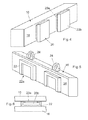
Figure 2 is a front view of the undercarriage ofFigure 1 , -
Figure 3 is a plan view of the undercarriage ofFigures 1 and 2 , -
Figure 4 is a partial perspective view of the undercarriage ofFigures 1 to 3 , showing the formations that engage the formations on the counterweight, -
Figure 5 is a perspective view of a counterweight showing the formations that engage the formations on the undercarriage, -
Figure 6 shows a horizontal section through the formations on the undercarriage and the counterweight when engaged with one another, and -
Figure 7 is a photograph showing a counterweight of the invention mounted on the undercarriage of a track driven excavator. - The
undercarriage 10 isFigure 1 has aturntable 12 on which there is rotatably mounted a structure (seeFigure 7 ) that includes, amongst other things, the operator cab and the lifting arm of a mobile excavator or crane. The illustrated undercarriage is driven by twoendless tracks 14 but the invention is equally applicable to a vehicle that is wheel driven. - In any such vehicle, to reduce the possibility of tipping when lifting an unbalanced heavy load, especially when the lifting arm is extended, it is important for the undercarriage to be as wide and as heavy as possible. However, widening the undercarriage is not practical because of the need for it to be transported on an open road. For this reason, the illustrated undercarriage has two
counterweights 16 that are removably mounted on the sides of theundercarriage 10. - The use of removable counterweights has been proposed previously but in the prior art the counterweights had to be bolted to the undercarriage or mounted on a removable frame that was bolted to the undercarriage. As a result, the mounting and removing of the counterweights was a laborious and time consuming exercise.
- To overcome this disadvantage, the present invention, as best shown by
Figures 4 to 6 , provides large-headed formations 20 that protrude slightly from a verticallateral surface 18 of theundercarriage 10, the formations being formed in the illustrated embodiment on the parts of the undercarriage encircled by the endless tracks. Each of the large-headed formations 20 comprises astem 20a and ahead 20b that extends laterally beyond thestem 20a. - The
vertical side 26 of thecounterweights 16 facing the undercarriage 10 (seeFigure 5 ) has twomating formations 22 which are shaped and dimensioned to fit over the large-headed formations 20 on the side of the undercarriage. Thecounterweights 16 also haveeyelets 24 by means of which they can be attached to the lifting arm of the vehicle. - Each
formation 22 on thecounterweight 16, as illustrated, defines achannel 22a that is closed at its upper end and open at its lower so that it can be lowered onto one of theformations 20 of the undercarriage from above. In section, as most clearly seen inFigure 6 , eachformation 22 is C-shaped to engage around and behind the part of thehead 20b that projects beyond thestem 20a of the large-headed formation 20. In this way, when the counterweight is raised by the lifting arm using theeyelets 24 and lowered onto theformations 20 of theundercarriage 10, the weight of the counterweight is supported by the closed end of thechannel 22a and thecounterweight 16 is prevented by separating from theundercarriage 10. No other action needs therefore to be taken aside from lowering the counterweight into place and this operation can itself be carried out by a single operator controlling the lifting arm. - While parallel sided formations have been described, it is alternatively possible for the formations to taper, the
head 20b and thechannel 22a both being wider at the bottom than at the top. This reduces the positioning tolerance when the counterweight is being lowered into position while preventing its longitudinal to and fro movement once it is in place. In such a design, the angle of taper should be chosen sufficiently large to avoid jamming of the counterweight through taper lock. As well as, or instead of, thehead 20b and thechannel 22a being wider at the bottom that the top, it is possible for one or both of them to be thicker or deeper at the bottom than at the top, to prevent lateral movement of the counterweight towards and away from the undercarriage. - It will be appreciated that the shape of the formations is not restricted to that illustrated and any formation with an undercut can be used to achieve the same aim of retaining the counterweight against the side of the undercarriage without having to resort to fixings, such as bolts, to hold the counterweight in place.
Claims (4)
- A vehicle having a wheel or endless track (14) driven undercarriage (10) supporting a lifting arm, wherein the undercarriage (10) of the vehicle is provided with formations (20) on a vertical lateral surface (18) to engage with mating formations (22) on a vertical lateral surface of a removable counterweight (26), the formations (20) being shaped to engage by sliding the counterweight (16) in a vertical plane relative to the undercarriage (10) and, when engaged, to support the weight of the counterweight (16) vertically and prevent separation of the counterweight (16) from the undercarriage (10), the formations (20) being positioned to receive a removable counterweight (16) entirely at one side of said undercarriage.
- A vehicle as claimed in claim 1, wherein each counterweight (16) is additionally provided with means of attachment (24) so that it may be mounted and removed from the undercarriage (10) using the lifting arm of the vehicle.
- A vehicle as claimed in claim 1 or 2, wherein the channels (22a) and the heads (20b) are shaped to engage with one another by the action of lowering the counterweight (16) onto the formations (20) on the undercarriage (10).
- A vehicle as claimed in claim 3, wherein the formations (20,22) on at least one of the undercarriage (10) and the counterweight (16) are tapered, each being wider at the bottom than at the top.
Applications Claiming Priority (1)
| Application Number | Priority Date | Filing Date | Title |
|---|---|---|---|
| IT000952A ITTO20080952A1 (en) | 2008-12-18 | 2008-12-18 | VEHICLE WITH LIFTING ARM |
Publications (3)
| Publication Number | Publication Date |
|---|---|
| EP2202364A2 true EP2202364A2 (en) | 2010-06-30 |
| EP2202364A3 EP2202364A3 (en) | 2014-01-22 |
| EP2202364B1 EP2202364B1 (en) | 2016-08-24 |
Family
ID=41061126
Family Applications (1)
| Application Number | Title | Priority Date | Filing Date |
|---|---|---|---|
| EP09179571.6A Active EP2202364B1 (en) | 2008-12-18 | 2009-12-17 | Vehicle with lifting arm and with removable counterweight |
Country Status (2)
| Country | Link |
|---|---|
| EP (1) | EP2202364B1 (en) |
| IT (1) | ITTO20080952A1 (en) |
Cited By (2)
| Publication number | Priority date | Publication date | Assignee | Title |
|---|---|---|---|---|
| JP2018070339A (en) * | 2016-10-31 | 2018-05-10 | コベルコ建機株式会社 | Crawler crane and method for using the same |
| CN114877021A (en) * | 2022-05-20 | 2022-08-09 | 长沙天盾重工有限责任公司 | Counterweight, counterweight assembling tool, counterweight assembling method and overhead working truck |
Citations (10)
| Publication number | Priority date | Publication date | Assignee | Title |
|---|---|---|---|---|
| JPS549416U (en) * | 1977-06-23 | 1979-01-22 | ||
| JPS5756689U (en) * | 1980-09-22 | 1982-04-02 | ||
| EP0071796A1 (en) * | 1981-08-08 | 1983-02-16 | Karl Schaeff GmbH & Co. | Articulated vehicle with a transversally movable counterpoise |
| JPS58199275A (en) * | 1982-05-13 | 1983-11-19 | Mitsuhiro Kishi | Mechanism for controlling center of gravity of high-place working vehicle |
| JPS59136385U (en) * | 1983-03-02 | 1984-09-11 | 株式会社クボタ | Vehicle weight device |
| JPS63185853U (en) * | 1987-05-25 | 1988-11-29 | ||
| DE9404670U1 (en) * | 1993-10-09 | 1995-02-09 | Orenstein & Koppel Ag | Adjustable counterweight for a construction machine and hydraulic excavator, which is equipped with an adjustable counterweight |
| US5460246A (en) * | 1993-08-23 | 1995-10-24 | O'flaherty Finance | Articulated aerial lift |
| KR100611716B1 (en) * | 2005-02-24 | 2006-08-11 | 볼보 컨스트럭션 이키프먼트 홀딩 스웨덴 에이비 | Shim attached with counter weight |
| WO2008010033A1 (en) * | 2006-07-12 | 2008-01-24 | Laurini Officine Meccaniche S.R.L. | Pipe-laying machine |
Family Cites Families (2)
| Publication number | Priority date | Publication date | Assignee | Title |
|---|---|---|---|---|
| GB708042A (en) * | 1951-04-11 | 1954-04-28 | Ruston Bucyrus Ltd | Improvements in or relating to dragline excavators |
| JP2007186926A (en) * | 2006-01-13 | 2007-07-26 | Hitachi Constr Mach Co Ltd | Construction machine |
-
2008
- 2008-12-18 IT IT000952A patent/ITTO20080952A1/en unknown
-
2009
- 2009-12-17 EP EP09179571.6A patent/EP2202364B1/en active Active
Patent Citations (10)
| Publication number | Priority date | Publication date | Assignee | Title |
|---|---|---|---|---|
| JPS549416U (en) * | 1977-06-23 | 1979-01-22 | ||
| JPS5756689U (en) * | 1980-09-22 | 1982-04-02 | ||
| EP0071796A1 (en) * | 1981-08-08 | 1983-02-16 | Karl Schaeff GmbH & Co. | Articulated vehicle with a transversally movable counterpoise |
| JPS58199275A (en) * | 1982-05-13 | 1983-11-19 | Mitsuhiro Kishi | Mechanism for controlling center of gravity of high-place working vehicle |
| JPS59136385U (en) * | 1983-03-02 | 1984-09-11 | 株式会社クボタ | Vehicle weight device |
| JPS63185853U (en) * | 1987-05-25 | 1988-11-29 | ||
| US5460246A (en) * | 1993-08-23 | 1995-10-24 | O'flaherty Finance | Articulated aerial lift |
| DE9404670U1 (en) * | 1993-10-09 | 1995-02-09 | Orenstein & Koppel Ag | Adjustable counterweight for a construction machine and hydraulic excavator, which is equipped with an adjustable counterweight |
| KR100611716B1 (en) * | 2005-02-24 | 2006-08-11 | 볼보 컨스트럭션 이키프먼트 홀딩 스웨덴 에이비 | Shim attached with counter weight |
| WO2008010033A1 (en) * | 2006-07-12 | 2008-01-24 | Laurini Officine Meccaniche S.R.L. | Pipe-laying machine |
Cited By (2)
| Publication number | Priority date | Publication date | Assignee | Title |
|---|---|---|---|---|
| JP2018070339A (en) * | 2016-10-31 | 2018-05-10 | コベルコ建機株式会社 | Crawler crane and method for using the same |
| CN114877021A (en) * | 2022-05-20 | 2022-08-09 | 长沙天盾重工有限责任公司 | Counterweight, counterweight assembling tool, counterweight assembling method and overhead working truck |
Also Published As
| Publication number | Publication date |
|---|---|
| EP2202364B1 (en) | 2016-08-24 |
| EP2202364A3 (en) | 2014-01-22 |
| ITTO20080952A1 (en) | 2010-06-19 |
Similar Documents
| Publication | Publication Date | Title |
|---|---|---|
| US8033572B2 (en) | Vehicle, in particular construction vehicle | |
| US10407283B2 (en) | Moving device for counterweight | |
| EP2436638B1 (en) | Crane transition assisting device, transport trailer with assisting device and crane disassembling/assembling method by use of assisting device | |
| US7845503B2 (en) | Pipe-laying machine | |
| US4921075A (en) | Fork lift | |
| KR101552554B1 (en) | Counterweight for heavy-duty lift device | |
| EP2202364B1 (en) | Vehicle with lifting arm and with removable counterweight | |
| CA2211825C (en) | Guide rail for a crawler track | |
| KR20110070940A (en) | Counter weight structure of a heavy equipment | |
| JP4763119B2 (en) | Crawler mounted crane | |
| US10343876B2 (en) | Mobile crane | |
| US11608256B1 (en) | Clamp with replaceable wear shoes | |
| US11702159B2 (en) | Mounting arrangement for tensioning units in tracked undercarriages of large machines | |
| RU2379426C2 (en) | Unified excavator | |
| CN206052829U (en) | For the supporting construction and machinery of mechanical frame | |
| JP7057322B2 (en) | Work vehicle | |
| US11878900B1 (en) | Lift truck clamp with wear rib | |
| WO2016072975A1 (en) | Push block module for front end of motor graders | |
| CN210682975U (en) | Hoisting walking frame of low-altitude crane | |
| CN211056584U (en) | Rope climbing prevention device | |
| CN218058214U (en) | Crawler crane with level indicator for road construction | |
| CN220448857U (en) | Auxiliary dismantling device for spiral conveyor of shield tunneling machine | |
| CN210682976U (en) | Crane walking frame safer to use | |
| CN210682977U (en) | Crane walking frame capable of reducing slippage probability | |
| CN207551746U (en) | A kind of crane and monkey |
Legal Events
| Date | Code | Title | Description |
|---|---|---|---|
| PUAI | Public reference made under article 153(3) epc to a published international application that has entered the european phase |
Free format text: ORIGINAL CODE: 0009012 |
|
| AK | Designated contracting states |
Kind code of ref document: A2 Designated state(s): AT BE BG CH CY CZ DE DK EE ES FI FR GB GR HR HU IE IS IT LI LT LU LV MC MK MT NL NO PL PT RO SE SI SK SM TR |
|
| RIN1 | Information on inventor provided before grant (corrected) |
Inventor name: CAPORALE, DAVIDE Inventor name: BELLINO, MARILENA |
|
| PUAL | Search report despatched |
Free format text: ORIGINAL CODE: 0009013 |
|
| AK | Designated contracting states |
Kind code of ref document: A3 Designated state(s): AT BE BG CH CY CZ DE DK EE ES FI FR GB GR HR HU IE IS IT LI LT LU LV MC MK MT NL NO PL PT RO SE SI SK SM TR |
|
| RIC1 | Information provided on ipc code assigned before grant |
Ipc: B62D 37/04 20060101ALI20131219BHEP Ipc: B66C 23/74 20060101ALI20131219BHEP Ipc: E02F 9/18 20060101AFI20131219BHEP Ipc: B62D 55/10 20060101ALI20131219BHEP Ipc: B66F 11/04 20060101ALI20131219BHEP Ipc: B66C 23/76 20060101ALI20131219BHEP Ipc: E02F 9/02 20060101ALI20131219BHEP |
|
| 17P | Request for examination filed |
Effective date: 20140722 |
|
| RBV | Designated contracting states (corrected) |
Designated state(s): AT BE BG CH CY CZ DE DK EE ES FI FR GB GR HR HU IE IS IT LI LT LU LV MC MK MT NL NO PL PT RO SE SI SK SM TR |
|
| 17Q | First examination report despatched |
Effective date: 20150617 |
|
| GRAP | Despatch of communication of intention to grant a patent |
Free format text: ORIGINAL CODE: EPIDOSNIGR1 |
|
| INTG | Intention to grant announced |
Effective date: 20160428 |
|
| GRAS | Grant fee paid |
Free format text: ORIGINAL CODE: EPIDOSNIGR3 |
|
| GRAA | (expected) grant |
Free format text: ORIGINAL CODE: 0009210 |
|
| AK | Designated contracting states |
Kind code of ref document: B1 Designated state(s): AT BE BG CH CY CZ DE DK EE ES FI FR GB GR HR HU IE IS IT LI LT LU LV MC MK MT NL NO PL PT RO SE SI SK SM TR |
|
| REG | Reference to a national code |
Ref country code: GB Ref legal event code: FG4D |
|
| REG | Reference to a national code |
Ref country code: CH Ref legal event code: EP |
|
| REG | Reference to a national code |
Ref country code: DE Ref legal event code: R084 Ref document number: 602009040576 Country of ref document: DE |
|
| REG | Reference to a national code |
Ref country code: AT Ref legal event code: REF Ref document number: 823237 Country of ref document: AT Kind code of ref document: T Effective date: 20160915 |
|
| REG | Reference to a national code |
Ref country code: IE Ref legal event code: FG4D |
|
| REG | Reference to a national code |
Ref country code: DE Ref legal event code: R096 Ref document number: 602009040576 Country of ref document: DE |
|
| REG | Reference to a national code |
Ref country code: FR Ref legal event code: PLFP Year of fee payment: 8 |
|
| REG | Reference to a national code |
Ref country code: GB Ref legal event code: 746 Effective date: 20160929 |
|
| REG | Reference to a national code |
Ref country code: LT Ref legal event code: MG4D |
|
| REG | Reference to a national code |
Ref country code: NL Ref legal event code: MP Effective date: 20160824 |
|
| REG | Reference to a national code |
Ref country code: AT Ref legal event code: MK05 Ref document number: 823237 Country of ref document: AT Kind code of ref document: T Effective date: 20160824 |
|
| PG25 | Lapsed in a contracting state [announced via postgrant information from national office to epo] |
Ref country code: LT Free format text: LAPSE BECAUSE OF FAILURE TO SUBMIT A TRANSLATION OF THE DESCRIPTION OR TO PAY THE FEE WITHIN THE PRESCRIBED TIME-LIMIT Effective date: 20160824 Ref country code: HR Free format text: LAPSE BECAUSE OF FAILURE TO SUBMIT A TRANSLATION OF THE DESCRIPTION OR TO PAY THE FEE WITHIN THE PRESCRIBED TIME-LIMIT Effective date: 20160824 Ref country code: NO Free format text: LAPSE BECAUSE OF FAILURE TO SUBMIT A TRANSLATION OF THE DESCRIPTION OR TO PAY THE FEE WITHIN THE PRESCRIBED TIME-LIMIT Effective date: 20161124 Ref country code: NL Free format text: LAPSE BECAUSE OF FAILURE TO SUBMIT A TRANSLATION OF THE DESCRIPTION OR TO PAY THE FEE WITHIN THE PRESCRIBED TIME-LIMIT Effective date: 20160824 Ref country code: FI Free format text: LAPSE BECAUSE OF FAILURE TO SUBMIT A TRANSLATION OF THE DESCRIPTION OR TO PAY THE FEE WITHIN THE PRESCRIBED TIME-LIMIT Effective date: 20160824 |
|
| PG25 | Lapsed in a contracting state [announced via postgrant information from national office to epo] |
Ref country code: LV Free format text: LAPSE BECAUSE OF FAILURE TO SUBMIT A TRANSLATION OF THE DESCRIPTION OR TO PAY THE FEE WITHIN THE PRESCRIBED TIME-LIMIT Effective date: 20160824 Ref country code: ES Free format text: LAPSE BECAUSE OF FAILURE TO SUBMIT A TRANSLATION OF THE DESCRIPTION OR TO PAY THE FEE WITHIN THE PRESCRIBED TIME-LIMIT Effective date: 20160824 Ref country code: PT Free format text: LAPSE BECAUSE OF FAILURE TO SUBMIT A TRANSLATION OF THE DESCRIPTION OR TO PAY THE FEE WITHIN THE PRESCRIBED TIME-LIMIT Effective date: 20161226 Ref country code: GR Free format text: LAPSE BECAUSE OF FAILURE TO SUBMIT A TRANSLATION OF THE DESCRIPTION OR TO PAY THE FEE WITHIN THE PRESCRIBED TIME-LIMIT Effective date: 20161125 Ref country code: SE Free format text: LAPSE BECAUSE OF FAILURE TO SUBMIT A TRANSLATION OF THE DESCRIPTION OR TO PAY THE FEE WITHIN THE PRESCRIBED TIME-LIMIT Effective date: 20160824 Ref country code: AT Free format text: LAPSE BECAUSE OF FAILURE TO SUBMIT A TRANSLATION OF THE DESCRIPTION OR TO PAY THE FEE WITHIN THE PRESCRIBED TIME-LIMIT Effective date: 20160824 |
|
| PG25 | Lapsed in a contracting state [announced via postgrant information from national office to epo] |
Ref country code: RO Free format text: LAPSE BECAUSE OF FAILURE TO SUBMIT A TRANSLATION OF THE DESCRIPTION OR TO PAY THE FEE WITHIN THE PRESCRIBED TIME-LIMIT Effective date: 20160824 Ref country code: EE Free format text: LAPSE BECAUSE OF FAILURE TO SUBMIT A TRANSLATION OF THE DESCRIPTION OR TO PAY THE FEE WITHIN THE PRESCRIBED TIME-LIMIT Effective date: 20160824 |
|
| REG | Reference to a national code |
Ref country code: DE Ref legal event code: R097 Ref document number: 602009040576 Country of ref document: DE |
|
| PG25 | Lapsed in a contracting state [announced via postgrant information from national office to epo] |
Ref country code: SM Free format text: LAPSE BECAUSE OF FAILURE TO SUBMIT A TRANSLATION OF THE DESCRIPTION OR TO PAY THE FEE WITHIN THE PRESCRIBED TIME-LIMIT Effective date: 20160824 Ref country code: BG Free format text: LAPSE BECAUSE OF FAILURE TO SUBMIT A TRANSLATION OF THE DESCRIPTION OR TO PAY THE FEE WITHIN THE PRESCRIBED TIME-LIMIT Effective date: 20161124 Ref country code: CZ Free format text: LAPSE BECAUSE OF FAILURE TO SUBMIT A TRANSLATION OF THE DESCRIPTION OR TO PAY THE FEE WITHIN THE PRESCRIBED TIME-LIMIT Effective date: 20160824 Ref country code: DK Free format text: LAPSE BECAUSE OF FAILURE TO SUBMIT A TRANSLATION OF THE DESCRIPTION OR TO PAY THE FEE WITHIN THE PRESCRIBED TIME-LIMIT Effective date: 20160824 Ref country code: SK Free format text: LAPSE BECAUSE OF FAILURE TO SUBMIT A TRANSLATION OF THE DESCRIPTION OR TO PAY THE FEE WITHIN THE PRESCRIBED TIME-LIMIT Effective date: 20160824 Ref country code: PL Free format text: LAPSE BECAUSE OF FAILURE TO SUBMIT A TRANSLATION OF THE DESCRIPTION OR TO PAY THE FEE WITHIN THE PRESCRIBED TIME-LIMIT Effective date: 20160824 Ref country code: BE Free format text: LAPSE BECAUSE OF FAILURE TO SUBMIT A TRANSLATION OF THE DESCRIPTION OR TO PAY THE FEE WITHIN THE PRESCRIBED TIME-LIMIT Effective date: 20160824 |
|
| PLBE | No opposition filed within time limit |
Free format text: ORIGINAL CODE: 0009261 |
|
| STAA | Information on the status of an ep patent application or granted ep patent |
Free format text: STATUS: NO OPPOSITION FILED WITHIN TIME LIMIT |
|
| REG | Reference to a national code |
Ref country code: CH Ref legal event code: PL |
|
| 26N | No opposition filed |
Effective date: 20170526 |
|
| PG25 | Lapsed in a contracting state [announced via postgrant information from national office to epo] |
Ref country code: SI Free format text: LAPSE BECAUSE OF FAILURE TO SUBMIT A TRANSLATION OF THE DESCRIPTION OR TO PAY THE FEE WITHIN THE PRESCRIBED TIME-LIMIT Effective date: 20160824 |
|
| PG25 | Lapsed in a contracting state [announced via postgrant information from national office to epo] |
Ref country code: MC Free format text: LAPSE BECAUSE OF FAILURE TO SUBMIT A TRANSLATION OF THE DESCRIPTION OR TO PAY THE FEE WITHIN THE PRESCRIBED TIME-LIMIT Effective date: 20160824 |
|
| REG | Reference to a national code |
Ref country code: IE Ref legal event code: MM4A |
|
| REG | Reference to a national code |
Ref country code: FR Ref legal event code: PLFP Year of fee payment: 9 |
|
| PG25 | Lapsed in a contracting state [announced via postgrant information from national office to epo] |
Ref country code: LI Free format text: LAPSE BECAUSE OF NON-PAYMENT OF DUE FEES Effective date: 20161231 Ref country code: CH Free format text: LAPSE BECAUSE OF NON-PAYMENT OF DUE FEES Effective date: 20161231 Ref country code: LU Free format text: LAPSE BECAUSE OF NON-PAYMENT OF DUE FEES Effective date: 20161217 |
|
| PG25 | Lapsed in a contracting state [announced via postgrant information from national office to epo] |
Ref country code: IE Free format text: LAPSE BECAUSE OF NON-PAYMENT OF DUE FEES Effective date: 20161217 |
|
| PG25 | Lapsed in a contracting state [announced via postgrant information from national office to epo] |
Ref country code: HU Free format text: LAPSE BECAUSE OF FAILURE TO SUBMIT A TRANSLATION OF THE DESCRIPTION OR TO PAY THE FEE WITHIN THE PRESCRIBED TIME-LIMIT; INVALID AB INITIO Effective date: 20091217 Ref country code: CY Free format text: LAPSE BECAUSE OF FAILURE TO SUBMIT A TRANSLATION OF THE DESCRIPTION OR TO PAY THE FEE WITHIN THE PRESCRIBED TIME-LIMIT Effective date: 20160824 |
|
| PG25 | Lapsed in a contracting state [announced via postgrant information from national office to epo] |
Ref country code: TR Free format text: LAPSE BECAUSE OF FAILURE TO SUBMIT A TRANSLATION OF THE DESCRIPTION OR TO PAY THE FEE WITHIN THE PRESCRIBED TIME-LIMIT Effective date: 20160824 Ref country code: IS Free format text: LAPSE BECAUSE OF FAILURE TO SUBMIT A TRANSLATION OF THE DESCRIPTION OR TO PAY THE FEE WITHIN THE PRESCRIBED TIME-LIMIT Effective date: 20160824 Ref country code: MK Free format text: LAPSE BECAUSE OF FAILURE TO SUBMIT A TRANSLATION OF THE DESCRIPTION OR TO PAY THE FEE WITHIN THE PRESCRIBED TIME-LIMIT Effective date: 20160824 |
|
| PG25 | Lapsed in a contracting state [announced via postgrant information from national office to epo] |
Ref country code: MT Free format text: LAPSE BECAUSE OF NON-PAYMENT OF DUE FEES Effective date: 20161217 |
|
| REG | Reference to a national code |
Ref country code: FR Ref legal event code: PLFP Year of fee payment: 10 |
|
| PGFP | Annual fee paid to national office [announced via postgrant information from national office to epo] |
Ref country code: GB Payment date: 20191220 Year of fee payment: 11 |
|
| REG | Reference to a national code |
Ref country code: DE Ref legal event code: R082 Ref document number: 602009040576 Country of ref document: DE Representative=s name: MEISSNER BOLTE PATENTANWAELTE RECHTSANWAELTE P, DE |
|
| GBPC | Gb: european patent ceased through non-payment of renewal fee |
Effective date: 20201217 |
|
| PG25 | Lapsed in a contracting state [announced via postgrant information from national office to epo] |
Ref country code: GB Free format text: LAPSE BECAUSE OF NON-PAYMENT OF DUE FEES Effective date: 20201217 |
|
| PGFP | Annual fee paid to national office [announced via postgrant information from national office to epo] |
Ref country code: FR Payment date: 20221216 Year of fee payment: 14 |
|
| PGFP | Annual fee paid to national office [announced via postgrant information from national office to epo] |
Ref country code: DE Payment date: 20221229 Year of fee payment: 14 |
|
| PGFP | Annual fee paid to national office [announced via postgrant information from national office to epo] |
Ref country code: IT Payment date: 20231127 Year of fee payment: 15 |