EP2441543A1 - Drilling tool - Google Patents
Drilling tool Download PDFInfo
- Publication number
- EP2441543A1 EP2441543A1 EP10786126A EP10786126A EP2441543A1 EP 2441543 A1 EP2441543 A1 EP 2441543A1 EP 10786126 A EP10786126 A EP 10786126A EP 10786126 A EP10786126 A EP 10786126A EP 2441543 A1 EP2441543 A1 EP 2441543A1
- Authority
- EP
- European Patent Office
- Prior art keywords
- tool
- end side
- groove
- sub
- chip discharge
- Prior art date
- Legal status (The legal status is an assumption and is not a legal conclusion. Google has not performed a legal analysis and makes no representation as to the accuracy of the status listed.)
- Granted
Links
Images


Classifications
-
- B—PERFORMING OPERATIONS; TRANSPORTING
- B23—MACHINE TOOLS; METAL-WORKING NOT OTHERWISE PROVIDED FOR
- B23B—TURNING; BORING
- B23B51/00—Tools for drilling machines
-
- B—PERFORMING OPERATIONS; TRANSPORTING
- B23—MACHINE TOOLS; METAL-WORKING NOT OTHERWISE PROVIDED FOR
- B23B—TURNING; BORING
- B23B51/00—Tools for drilling machines
- B23B51/02—Twist drills
-
- B—PERFORMING OPERATIONS; TRANSPORTING
- B23—MACHINE TOOLS; METAL-WORKING NOT OTHERWISE PROVIDED FOR
- B23B—TURNING; BORING
- B23B2251/00—Details of tools for drilling machines
- B23B2251/08—Side or plan views of cutting edges
- B23B2251/085—Discontinuous or interrupted cutting edges
-
- B—PERFORMING OPERATIONS; TRANSPORTING
- B23—MACHINE TOOLS; METAL-WORKING NOT OTHERWISE PROVIDED FOR
- B23B—TURNING; BORING
- B23B2251/00—Details of tools for drilling machines
- B23B2251/14—Configuration of the cutting part, i.e. the main cutting edges
-
- B—PERFORMING OPERATIONS; TRANSPORTING
- B23—MACHINE TOOLS; METAL-WORKING NOT OTHERWISE PROVIDED FOR
- B23B—TURNING; BORING
- B23B2251/00—Details of tools for drilling machines
- B23B2251/24—Overall form of drilling tools
- B23B2251/241—Cross sections of the diameter of the drill
- B23B2251/244—Cross sections of the diameter of the drill decreasing in a direction towards the shank from the tool tip
-
- B—PERFORMING OPERATIONS; TRANSPORTING
- B23—MACHINE TOOLS; METAL-WORKING NOT OTHERWISE PROVIDED FOR
- B23B—TURNING; BORING
- B23B2251/00—Details of tools for drilling machines
- B23B2251/40—Flutes, i.e. chip conveying grooves
- B23B2251/404—Flutes, i.e. chip conveying grooves with decreasing depth in a direction towards the shank from the tool tip
-
- B—PERFORMING OPERATIONS; TRANSPORTING
- B23—MACHINE TOOLS; METAL-WORKING NOT OTHERWISE PROVIDED FOR
- B23B—TURNING; BORING
- B23B2251/00—Details of tools for drilling machines
- B23B2251/40—Flutes, i.e. chip conveying grooves
- B23B2251/406—Flutes, i.e. chip conveying grooves of special form not otherwise provided for
-
- Y—GENERAL TAGGING OF NEW TECHNOLOGICAL DEVELOPMENTS; GENERAL TAGGING OF CROSS-SECTIONAL TECHNOLOGIES SPANNING OVER SEVERAL SECTIONS OF THE IPC; TECHNICAL SUBJECTS COVERED BY FORMER USPC CROSS-REFERENCE ART COLLECTIONS [XRACs] AND DIGESTS
- Y10—TECHNICAL SUBJECTS COVERED BY FORMER USPC
- Y10T—TECHNICAL SUBJECTS COVERED BY FORMER US CLASSIFICATION
- Y10T408/00—Cutting by use of rotating axially moving tool
- Y10T408/89—Tool or Tool with support
- Y10T408/905—Having stepped cutting edges
-
- Y—GENERAL TAGGING OF NEW TECHNOLOGICAL DEVELOPMENTS; GENERAL TAGGING OF CROSS-SECTIONAL TECHNOLOGIES SPANNING OVER SEVERAL SECTIONS OF THE IPC; TECHNICAL SUBJECTS COVERED BY FORMER USPC CROSS-REFERENCE ART COLLECTIONS [XRACs] AND DIGESTS
- Y10—TECHNICAL SUBJECTS COVERED BY FORMER USPC
- Y10T—TECHNICAL SUBJECTS COVERED BY FORMER US CLASSIFICATION
- Y10T408/00—Cutting by use of rotating axially moving tool
- Y10T408/89—Tool or Tool with support
- Y10T408/909—Having peripherally spaced cutting edges
- Y10T408/9095—Having peripherally spaced cutting edges with axially extending relief channel
-
- Y—GENERAL TAGGING OF NEW TECHNOLOGICAL DEVELOPMENTS; GENERAL TAGGING OF CROSS-SECTIONAL TECHNOLOGIES SPANNING OVER SEVERAL SECTIONS OF THE IPC; TECHNICAL SUBJECTS COVERED BY FORMER USPC CROSS-REFERENCE ART COLLECTIONS [XRACs] AND DIGESTS
- Y10—TECHNICAL SUBJECTS COVERED BY FORMER USPC
- Y10T—TECHNICAL SUBJECTS COVERED BY FORMER US CLASSIFICATION
- Y10T408/00—Cutting by use of rotating axially moving tool
- Y10T408/89—Tool or Tool with support
- Y10T408/909—Having peripherally spaced cutting edges
- Y10T408/9095—Having peripherally spaced cutting edges with axially extending relief channel
- Y10T408/9097—Spiral channel
Definitions
- the present invention relates to a drilling tool.
- a nicked drill in which a nick for dividing chips is provided by cutting a part of the drill tip end along a flank face (for example, refer to Patent Literature 1).
- This nicked drill is configured so that each of a plurality of cutting edges has a plurality of concave groove-like nicks vertical to the cutting edge. These nicks are arranged in the cutting edges so that the rotation trajectories of the nicks in the circumferential direction around the axis line are different with respect to the cutting edges adjacent to one another, and thereby the nicks divide chips in the width direction within a short range of each nick.
- nicks provided from the cutting edge along the flank face causes a possibility where a cutting edge at the drill tip end may be grinded together with the nick periphery to thereby eliminate the existence of the nick.
- a disadvantage has been caused where the nick function must be maintained by forming, prior to the use of the drill, the nicks of the drill repeatedly by a grinding machining. If the nicks are formed in an extended manner in the vertical direction to the cutting edge in order to avoid the repeated machining of the drill for forming the nicks as described above, a disadvantage of deteriorated cutting edge strength is caused.
- the nicks arranged so that a rotational trajectory of the nicks are dislocated with respect to the cutting edges adjacent to one another in the circumferential direction around the axis line.
- the nicks are prevented from having a freely-set groove width, position, or number, and thus causing limitation on the width of chips that can be divided.
- Patent Literature 1 is also disadvantageous in that the invention of Patent Literature 1 cannot be applied to a one-blade rotation tool because of the configuration where the chip of the residual stock after forming of a machined hole by the nicks cut by a preceding cutting edge in the drill rotation direction is cut by a subsequent cutting edge having a dislocated nick rotation trajectory.
- Patent Literature2 a method of providing more minute chips according to which a rake face is formed to have a step-like shape having at least one step section so that the cutting edge is divided in the diameter direction of the tool body.
- the drilling tool as described above does not need to perform the machining for forming nicks that is repeatedly performed in order to grind the cutting edge.
- This drilling tool can change the number of the step sections or the width in the diameter direction for example to adjust the lengths of the respective divided cutting edges in the diameter direction.
- chips can be segmentalized to have a desired width.
- This drilling tool also can be applied to a one-blade gun drill or a reamer for example.
- the rake face is formed to have a step-like shape as described above, many parts are required to form grooves for discharging chips, which causes a concern that the tool may have a declined rigidity when the tool is used for a deep hole machining drill.
- the present invention has been made in view of the above-described circumstance. It is an objective of the present invention to provide a rotation tool having superior chip controllability and tool rigidity by which chips can be segmentalized to have a desired width.
- the present invention uses the following means.
- the present invention provides a drilling tool that includes: a tool body having an outer shape having a substantially cylindrical shape rotated around an axis line; a chip discharge groove formed in an outer periphery of the tool body to extend from a tip end face of the tool body to a rear end side; at least one sub-groove that is formed at an inner face facing a front side in a tool rotation direction of the chip discharge groove and that are formed to extend from a tip end face of the tool body to a rear end side; a rake face formed at an inner face facing the front side in the tool rotation direction of the chip discharge groove and the at least one sub-groove, respectively; a tip end flank face formed at a tip end face of the tool body; and a cutting edge formed at a ridge line at which the tip end flank face intersects with the rake face.
- the inner face facing the front side in the tool rotation direction of the chip discharge groove is formed by the rake face to have a step-like shape having at least one step section.
- a turnup section at the rear end side of the sub-groove is turned up in a different direction from the direction along which the rear end side of the chip discharge groove is turned up.
- the drilling tool has a plurality of rake faces and the plurality of rake faces form a step-like step section.
- Cutting edges provided at the ridge line of the edges of the respective rake faces are discontinuously arranged in a step-like manner and spaced in the front-and-rear direction of the tool rotation direction.
- chips are segmentalized to have a narrow width, thus improving the chip controllability.
- the number of the sub-grooves or the width for example can be appropriately selected to thereby allowing, without being limited by the design, the respective cutting edges to have a desired length in the diameter direction. Therefore, chips can be segmentalized to have a desired width.
- the rake face shape and the chip discharge groove shape of the present invention also can be applied to a one-blade gun drill or a reamer to segmentalize chips.
- the turnup section of the sub-groove is turned up in a different direction from that along which the turnup section of the chip discharge groove is turned up.
- the turnup section of the chip discharge groove may be gradually turned up along an inner face facing the front side in the tool rotation direction in a direction from the center side of the tool body to the outer periphery side.
- the turnup section of the chip discharge groove is turned up in the same direction as that of the turnup section of the chip discharge groove of a general-purpose drill and thus can be machined in a conventional manner.
- the turnup section of the sub-groove is not turned up along the inner face facing the front side in the tool rotation direction of the chip discharge groove in a direction from the center side of the tool body toward the outer periphery side but is turned up in a different direction from the above direction.
- chips reaching the turnup section of the sub-groove will be pushed out, at the turnup section of the sub-groove, toward the outer periphery side of the tool body in a different direction from that of the turnup section of the chip discharge groove.
- chips reaching the turnup section of the sub-groove will be pushed out, at the turnup section of the sub-groove, toward the outer periphery side of the tool body in a different direction from that of the turnup section of the chip discharge groove.
- the turnup section of the sub-groove may be gradually turned up in a direction substantially vertical to the inner face facing the front side in the tool rotation direction of the sub-groove, as a position progresses in a direction from the tip end side to the rear end side.
- chips in case that chips reaches the turnup section of the sub-groove, chips will be pushed out to the interior of the chip discharge groove.
- chips are prevented from clogging the turnup section of the sub-groove and are stored in the chip discharge groove and are discharged smoothly, thus providing a superior chip discharge property.
- the sub-groove may have a shorter length than a length of the chip discharge groove.
- the tool body when compared with a case where the sub-groove has substantially the same length as that of the chip discharge groove, the tool body has an increased thickness at the rear end side, thus providing improved tool rigidity.
- a sufficient tool rigidity is secured, thus suppressing chatter vibration or a broken tool.
- the tool body can be manufactured with a shorter time than in the case where the sub-groove has substantially the same length as that of the chip discharge groove.
- the tool body may have a back tapered structure in which an outer diameter is gradually reduced from the tip end side to the rear end side and a web at the rear end side of the tool body may have a thickness equal to or higher than a thickness of a web thickness of the tool body.
- the tool body may have a web tapered structure in which the web has a thickness gradually increased from the tip end side toward the rear end side.
- the tool rigidity can be improved when compared with a general back taper drill in which the web has a thickness corresponding to the back taper to be gradually reduced from the tip end side toward the rear end side.
- the web may have substantially the same thickness from the tip end side of the tool body toward the rear end side.
- the chip discharge groove can have an increased cross-sectional area, thus improving the chip discharge property.
- chips can be segmentalized to have a desired width, thus providing superior chip controllability and tool rigidity.
- a drilling tool 1 according to the present embodiment has a shape as shown in Fig. 1 in which an outer diameter has a substantially round bar-like shape.
- the drilling tool 1 includes: a tool body 2 that has a cutting part and that functions as a basic section of the drilling tool 1; and a shank 20 that is integrally formed at the rear end of the tool body 2 and that functions as a tool haft.
- the tool body 2 is formed by cemented carbide, cermet, ceramic, or ultrahigh pressure sintered body for example. As shown in Fig. 1 to Fig. 4 , the tool body 2 has a substantially cylindrical shape in the outer diameter direction rotated around the axis line ⁇ . This tool body 2 has: a chip discharge groove 4 that is formed at the outer periphery to extend from the tip end face to the rear end side; a tip end flank face 16 formed at a tip end face; and an oil hole 17 that is drilled in the interior and that is used to discharge cutting fluid.
- This tool body 2 has a cutting part tip end having an outer diameter size (i.e., diameter of the tool body 2) of 6.0mm for example.
- This tool body 2 has a back tapered shape in which the outer diameter is gradually reduced from the tip end side toward the rear end side (see Fig. 6 ).
- the tapered shape of the tool body 2 is shown in an exaggerated manner for a description purpose.
- the back taper amount of the tool body 2 is set to 0.04/100 or more and 0.06/100 or less and is set to 0.05/100 for example. As shown in Fig.
- a web taper along which the web 3 has a thickness gradually increased from the tip end side toward the rear end side is provided.
- the web 3 is formed between parts formed by the groove bottom of the chip discharge groove 4 and the sub-groove 7 that are formed to have 180-degree-rotationally-symmetrical shape to the axis line ⁇ of the tool body 2.
- the thickness of the web 3 at the tip end of the tool body 2 i.e., web thickness D
- the web taper amount of the tool body 2 is set so as to secure the rigidity of the tool body 2 and is set to 0.01/100 or more and 0.50/100 or less and is preferably set to 0.05/100 or more and 0.10/100 or less (for example, is set to 0.05/100).
- the chip discharge groove 4 is composed of a straight groove that extends to draw a straight line to be substantially parallel to the axis line ⁇ .
- the chip discharge groove 4 is formed, in the vicinity of the tip end of the tool body 2, to have an arc-like cross section having center angle of about 90 degrees.
- the inner face formed at the front side in the tool rotation direction T is formed so as to be gradually turn up in the substantially vertical direction to the inner face formed at the front side in the tool rotation direction T in a direction from the center side of the tool body 2 to the outer periphery side, as a position progresses from the tip end side of the tool body 2 to the rear end side, at a position having a fixed length from the tip end.
- a part corresponding to the turnup of the tool when this chip discharge groove 4 is machined (i.e., the turnup section 5 of the chip discharge groove 4) is formed so as to be turned up along the inner face 6 facing the front side of the tool rotation direction T of the chip discharge groove 4 in a direction from the center side of the tool body 2 toward the outer periphery side.
- two sub-grooves 7 are formed so as to extend from the tip end side to the rear end side.
- Rake faces 10 are formed at the tip end side of the inner face 6 of the chip discharge groove 4, in the vicinity of the sub-grooves 7, arranged at the inner side in the tool diameter direction of the sub-grooves 7.
- the sub-grooves 7 are formed so as to extend in a straight manner to be substantially parallel to the axis line ⁇ until a fixed length is reached from the tip end.
- a part corresponding to the turnup of the tool for machining the sub-grooves 7 i.e., the turnup sections 8 of the sub-grooves 7) are turned up in a different direction from the direction along which the turnup section 5 in the chip discharge groove 4 is turned up.
- the turnup section 5 of the chip discharge groove 4 is turned up from the center side of the tool body to the outer periphery side along the inner face facing the front side of the tool rotation direction in a direction from the tip end side to the rear end side.
- the turnup section 8 of the sub-groove 7 is gradually turned up in a substantially-vertical direction to the inner face 9 facing the front side in the tool rotation direction T of the sub-groove 7.
- the rake face 10 is also formed at the tip end side of the inner face 9 facing the front side in the tool rotation direction T of the sub-groove 7.
- Two sub-grooves 7 having a configuration as described above are provided to one chip discharge groove 4.
- Two sub-grooves 7 provided in one chip discharge groove 4 and two sub-grooves 7 provided in another chip discharge groove 4 are provided at 180 degree rotationally-symmetrical positions to the axis line ⁇ .
- two sub-grooves 7 are provided in the chip discharge groove 4.
- the present invention is not limited to this.
- one sub-groove 7 also may be formed in the chip discharge groove 4 or three or more sub-grooves 7 also may be formed in the chip discharge groove 4.
- These all sub-grooves 7 have lengths L2 that are measured in a direction parallel to the axis line ⁇ and that are substantially equal.
- the respective sub-grooves 7 When the tool body 2 is seen from the front side in a direction orthogonal to the axis line ⁇ , the respective sub-grooves 7 have the turnup sections 8 arranged at substantially the same positions.
- the respective sub-grooves 7 have the length L2 that is shorter than the length L1 of the chip discharge groove so that the turnup sections 8 of the respective sub-grooves 7 are positioned closer to the tip end than the turnup section 5 of the chip discharge groove 4.
- the sub-groove 7 has the length L2 that is equal to or higher than 20% and lower than 100% of the length L1 of the chip discharge groove 4 and that is preferably 40% or more and 60% or less of the length L1 of the chip discharge groove 4 and that is set to 50% of the length L1 of the chip discharge groove 4 for example.
- the respective sub-grooves 7 have the widths W in the tool diameter direction that are substantially equal so that the width of one chip discharge groove 4 in the tool diameter direction is equally divided to three parts by two sub-grooves 7 provided in the chip discharge groove 4.
- the sub-groove 7 has the width W set to be 0.2mm or more and 4.0mm or less and is preferably set to 0.4mm or more and 2.0mm or less and is set to 0.6mm for example.
- the rake face 10 is configured so that the rake face 10 formed in the chip discharge groove 4 and the rake faces 10 formed in the respective two sub-grooves 7 are arranged, as a result of that the three rake face are arranged to have an interval thereamong in the front-and-rear direction of the tool rotation direction T in a step-like manner to thereby form two step sections 11.
- Each rake face 10 has a substantially-equal width in the tool diameter direction that is set to 0.2mm or more and 4.0mm or less corresponding to the width W of the sub-groove 7 and that is preferably set to 0.4mm or more and 2.0mm or less corresponding to the width W of the sub-groove 7 and that is set to 0.6mm for example.
- the step section 11 is composed of the turnup face 12 turned up from the rake face 10 and the rake face 10 intersecting with the turnup face 12.
- This turnup face 12 provides a level difference Q between the respective rake faces 10.
- the level difference Q of the step section 11 is, for example, 1.5mm when being measured in the vertical direction to the rake face 10.
- This turnup face 12 is preferably inclined from the step section 11 to the inverse side in the tool rotation direction T and to the inner side in the tool diameter direction with regard to the tangent line N drawn by the rotation trajectory circle (the circle shown by the chain line in Fig. 5 ) drawn by the corner section of the step section 11 at which the turnup face 12 intersects with the rake face 10.
- the turnup face 12 has the inclination angle ⁇ of 15 degrees to the tangent line N.
- the two step sections 11 provided in one chip discharge groove 4 and two step sections 11 provided in another chip discharge groove 4, having the configuration as described above, are provided at 180-degree-rotationally-symmetrical positions to the axis line ⁇ .
- the cutting edges 14 are formed at the respective ridge lines at which the respective rake faces 10 intersect with the tip end flank face 16.
- the three neighboring cutting edges 14 are arranged discontinuously with an interval thereamong in the front-and-rear direction of the tool rotation direction T.
- the three cutting edges 14 provided in a step-like manner in the tool diameter direction constitute one cutting edge 15.
- One pair of cutting edges 15 is provided in a 180 degree-rotationally-symmetrical manner with respect to the axis line ⁇ to thereby constitute a drilling tool having two blades. These two cutting edges 15 are used to perform a drilling machining.
- the cutting edges 14 that are provided in a 180-degree-rotationally-symmetrical manner with respect to the axis line ⁇ are set to have substantially the same length. All of the cutting edge 14 have a substantially-equal length that is set so as to correspond to the width W of the sub-groove 7 in a range from 0.2mm or more to 4.0m or less and preferably in a range from 0.4mm or more to 2.0mm or less and that is set to 0.6mm for example.
- the two cutting edges 15 provided to surround the axis line ⁇ as a center in a 180-degree-rotationally-symmetricalmannerare composed of the three cutting edges 14 that are discontinuously arranged to have an interval thereamong in the front-and-rear direction of the tool rotation direction T, respectively.
- the respective cutting edges 14 can be used to generate chips having a width corresponding to the length of the cutting edges 14.
- one cutting edge 15 is divided by two step sections 11 to thereby provide the three cutting edges 14.
- three chips are generated that have a width corresponding to the length of the cutting edge 14 having an about 1/3 length of that of the cutting edge 15.
- Chips having a narrow width obtained through the segmentalization as described above can be easily deformed to have a curled shape quickly, thus providing a shape of superior chip controllabilily. This consequently suppresses the situation where chips are sandwitched between the tool body 2 and a workpiece to cause a damage of the cutting part section for example. This can consequently improve the accuracy of the finish surface roughness of the workpiece or the dimension accuracy and can improve the tool life.
- the turnup face 12 of the step section 11 is inclined to have the predetermined angle ⁇ to the tangent line N of the rotation trajectory circle drawn by the corner of the step section 11 toward the rear side of the tool rotation direction T and toward the inner side of the tool diameter direction, the inner periphery end of the subsequent cutting edge 14 provided at an immediate rear side of the corner corresponding to the outer periphery end of the previous cutting edge 14 in the tool rotation direction T is not involved in the cutting operation (see Fig. 5 ).
- an eliminating the level difference Q as a result of that chips during cutting are partially welded to the inner periphery end of the subsequent cutting edge 14, and so on, is inhibited.
- chips can be securely segmentalized.
- the drilling tool of the present invention allows the number of the sub-grooves 7 or the width W for example to be appropriately set depending on a required chip width.
- the respective cutting edges 14 can have a desired length without being limited due to a design reason.
- chips generated from the drilling tool 1 in this embodiment can be segmentalized to have a desired width and can have a further minute size.
- the three cutting edges 14 constituting the cutting edge 15 and the three cutting edges 14 constituting another cutting edge 15 are mutually provided at rotationally-symmetrical positions to the axis line ⁇ .
- the cutting edges 14 provided at 180 degree-rotationally-symmetrical positions to the axis line ⁇ have substantially the same length.
- cutting resistance is applied to the respective cutting edges 14 in a balanced and uniform manner to thereby apply a uniform cutting force to the respective cutting edges 14 during cutting.
- the tool is rotated stably to thereby suppress vibration from occurring.
- the machining hole has an improved machining accuracy (e.g., hole position accuracy, hole diameter size, roundness, straightness, finish surface roughness).
- All of the cutting edges 14 having substantially the same length mean that chips generated through the respective cutting edges 14 have a uniform width or deformation. Thus, a part of the chips can be prevented from having a long length, thus allowing chips to be stably machined through the respective cutting edges 14.
- the drilling tool 1 is formed so that the turnup section 5 of the sub-groove 7 is differently formed from the turnup section 5 of the chip discharge groove 4.
- the turnup section 5 of the sub-groove 7 is formed to be gradually turned up in a direction substantially vertical to the inner face 9 facing to the front side in the tool rotation direction T of the sub-groove 7.
- the drilling tool 1 has a superior chip discharge property by which the chipping due to sandwitched chips, a defective tool, or a damaged machining surface for example can be avoided.
- the tool life is extended and the machining accuracy is improved.
- the sub-groove 7 of the drilling tool 1 has the length L2 that is shorter than the length L1 of the chip discharge groove 4.
- the drilling tool 1 has an increased thickness at the rear end side of the tool body 2, thus providing a higher tool rigidity. Therefore, even when the cutting edge having the shape as described above is applied in a long tool such as a gun drill used for a deep hole machining, a sufficient tool rigidity is secured, thus suppressing chatter vibration or a broken tool.
- the sub-groove 7 having the length L2 shorter than the length L1 of the chip discharge groove 4 reduces the time required to machine the sub-groove 7. This provides a shorter manufacture time of the drilling tool 1 when compared with the conventional drilling tool 30 having the sub-groove 37 having the same length as that of the chip discharge groove 4, thus reducing the manufacturing cost.
- the drilling tool 1 can provide a superior chip discharge property.
- the drilling tool 1 has a web tapered structure in which the thickness of the web 3 is gradually increased from the tip end side of the tool body 2 to the rear end side, thus providing improved tool rigidity more than in the conventional case.
- the tool body 2 having a back tapered structure from the viewpoint of improving the tool rigidity has a web tapered structure as described above, the rear end side of the tool body 2 is prevented from having an increased cross-sectional area of the chip discharge groove 4, thus undesirably causing the chip discharge groove 4 to have a smaller cross-sectional area than that of the tip end side of the tool body 2.
- the step-like cutting edge 14 can be used to segmentalize chips with good chip controllability.
- chips can be prevented from clogging the rear end side of the tool body 2 or being sandwitched between the tool body 2 and the workpiece.
- the tool body 2 having a back tapered structure can have a web tapered structure, thus improving the tool rigidity.
- a chip discharge groove must have a certain level of a cross-sectional area in order to securely discharge chips.
- the web 43 is configured so that the web 43 is formed to correspond to the back taper to have a thickness decreased from the tip end side of the tool body 2 toward the rear end side. This means a possibility where an increased number of sub-grooves 37 causes a declined tool rigidity.
- a web tapered structure was used in the tool body 2 in which the web 3 has a thickness increased from the tip end side toward the rear end side.
- another configuration as shown in Fig. 7 also may be used where the web 3' has substantially the same thickness that is substantially the same as the thickness of the web thickness D over the entire length of the tool body 2.
- the tool rigidity is improved than in the case of the conventional back taper drill 40 in which the web 43 has a thickness gradually decreased from the tip end side of the tool body 2 to the rear end side.
- the number of the sub-grooves 7 is not particularly limited and can be set to an arbitrary number.
- an increase in the number of the sub-grooves 7 causes an increase in the number of the cutting edges 14, which causes the reduction in the length of one blade involved in a cutting operation.
- chips obtained through each cutting edge 14 have a reduced width.
- chips are divided in the width direction in the number corresponding to the number of the sub-grooves 7.
- a higher number of sub-grooves 7 is preferred from the viewpoint of chip segmentalization.
- chip segmentalized to have a width of about 1 to 4mm can be obtained by allowing one chip discharge groove 4 to include two to four sub-grooves 7 in the tool having a diameter of 12mm and by allowing one chip discharge groove 4 to include three to five sub-grooves 7 in the tool having a diameter of 16mm.
- the respective sub-grooves 7 have a substantially equal width W
- the chip discharge groove 4 has a width in the tool diameter direction that is equally divided to three parts by two sub-grooves 7, and all of the cutting edges 14 have substantially the same length.
- another configuration also may be used, for example, in which the width W of the sub-groove is equally divided to four or more parts or the respective sub-grooves also may have different widths so that the respective cutting edges 14 can have an arbitrary length depending on an intended use or use conditions.
- the reduction of the width W of the sub-groove 7 causes an increase in the number of the sub-grooves 7 that can be formed in one chip discharge groove 4 causes an increase of the number of the cutting edges 14.
- the length of one blade is reduced.
- the sub-groove 7 having a narrower width W is preferred from the viewpoint of chip segmentalization.
- the drilling tool 1 according to the present embodiment is configured so that all of the sub-grooves 7 have the same length L.
- another configuration also may be used in which the respective sub-grooves 7 adjacent to each other in one chip discharge groove 4 have lengths set to be gradually shorter from the inner side in the tool diameter direction toward the outer side. This configuration provides a further-improved tool rigidity.
- the drilling tool 1 is configured so that the turnup section 8 of the sub-groove 7 is gradually turned up from the tip end side toward the rear end side in a direction substantially vertical to the inner face 9 facing the front side in the tool rotation direction T of the sub-groove 7.
- the turnup section 8 of the sub-groove 7 also can be turned up in a different direction other than the above direction.
- the turnup section 8 of the sub-groove 7 also may be formed to be gradually turned up in a direction substantially vertical to the inner face 6 facing the front side in the tool rotation direction T of the chip discharge groove 4.
- the drilling tool 1 is configured so that the step section 11 has the level difference Q of 0.5mm and the turnup face 12 has the inclination angle ⁇ of 15 degrees.
- the drilling tool of the present invention also can be configured so that the level difference Q of the step section 11 and the inclination angle ⁇ of the turnup face 12 are not particularly limited and can be set to an arbitrary value.
- This step section 11 preferably has the level difference Q that is 0. 5mm or more and 2.0mm or less and that is advantageously 0.25mm or more and 1.0mm or less.
- the inclination angle ⁇ of the turnup face 12 is preferably 0 ⁇ 45 and is preferably 2.0 ⁇ 20.
- the inner periphery end of the subsequent cutting edge 14 is also subjected to a cutting operation.
- a situation may be caused where chips on the respective cutting edges 14 are connected without being divided and chips having a wide width are generated.
- the angle formed by the rake face 10 and the turnup face 12 is 90 degrees and the inclination angle ⁇ of the turnup face 12 to the tangent line N is 0 degree, chips may be partially welded to the inner periphery end of the subsequent cutting edge 14, and so on, due to a cutting operation, causing a possibility where the chips at the respective cutting edges may be connected without being divided.
- the inclination angle ⁇ of the turnup face 12 exceeding 45 degrees causes a risk where the drilling tool of the present invention cannot maintain the strength at the ridge line at which the rake face 10 intersects with the turnup face.
- the drilling tool 1 is a two-blade drill including the two cutting edges 15.
- the drilling tool of the present invention also may be one-blade drill or a three-blade drill.
- the cutting edges 14 constituting the respective three cutting edges 15 are arranged to be 120-degree-rotationally-symmetrical (three time symmetrical) to the axis line ⁇ , thus allowing the tool to rotate stably. This consequently suppresses vibration from occurring, thus further improving the machining surface quality and the dimension accuracy for example.
- a drilling tool has been illustratively described in order to describe the drilling tool of the present invention.
- the drilling tool of the present invention is not limited to this.
- the present invention also can be used for various drilling tools including general solid drill, blade drill, top solid drill, core drill, reamer, and boring cutter for example.
- the outer periphery of the tool body 2 also may include a margin from the viewpoint of improving the finish surface roughness or also may include a guide pad form the viewpoint of improving the guide property.
Landscapes
- Engineering & Computer Science (AREA)
- Mechanical Engineering (AREA)
- Drilling Tools (AREA)
Abstract
Description
- The present invention relates to a drilling tool.
- In recent years, in the case where a workpiece having a complicated shape such as an automobile engine member, etc. is subjected to a drilling machining, chips caused in the machining have been strongly required to be more minute from the viewpoint of improving the chip controllability.
- In order to satisfy this requirement, a nicked drill has been known in which a nick for dividing chips is provided by cutting a part of the drill tip end along a flank face (for example, refer to Patent Literature 1).
- This nicked drill is configured so that each of a plurality of cutting edges has a plurality of concave groove-like nicks vertical to the cutting edge. These nicks are arranged in the cutting edges so that the rotation trajectories of the nicks in the circumferential direction around the axis line are different with respect to the cutting edges adjacent to one another, and thereby the nicks divide chips in the width direction within a short range of each nick.
-
- PTL1: Japanese Patent Laid-Open No.
2007-50477 - PTL2: Japanese Patent Laid-Open No.
2009-202288 - However, in the case of the invention of
Patent Literature 1, nicks provided from the cutting edge along the flank face causes a possibility where a cutting edge at the drill tip end may be grinded together with the nick periphery to thereby eliminate the existence of the nick. Thus, a disadvantage has been caused where the nick function must be maintained by forming, prior to the use of the drill, the nicks of the drill repeatedly by a grinding machining. If the nicks are formed in an extended manner in the vertical direction to the cutting edge in order to avoid the repeated machining of the drill for forming the nicks as described above, a disadvantage of deteriorated cutting edge strength is caused. - Furthermore, the nicks arranged so that a rotational trajectory of the nicks are dislocated with respect to the cutting edges adjacent to one another in the circumferential direction around the axis line. Thus, the nicks are prevented from having a freely-set groove width, position, or number, and thus causing limitation on the width of chips that can be divided.
- Furthermore, the invention of
Patent Literature 1 is also disadvantageous in that the invention ofPatent Literature 1 cannot be applied to a one-blade rotation tool because of the configuration where the chip of the residual stock after forming of a machined hole by the nicks cut by a preceding cutting edge in the drill rotation direction is cut by a subsequent cutting edge having a dislocated nick rotation trajectory. - Thus, in order to solve the above disadvantages, the applicant of this application has suggested, in Patent Literature2, a method of providing more minute chips according to which a rake face is formed to have a step-like shape having at least one step section so that the cutting edge is divided in the diameter direction of the tool body. The drilling tool as described above does not need to perform the machining for forming nicks that is repeatedly performed in order to grind the cutting edge. This drilling tool can change the number of the step sections or the width in the diameter direction for example to adjust the lengths of the respective divided cutting edges in the diameter direction. Thus, chips can be segmentalized to have a desired width. This drilling tool also can be applied to a one-blade gun drill or a reamer for example.
- However, when the rake face is formed to have a step-like shape as described above, many parts are required to form grooves for discharging chips, which causes a concern that the tool may have a declined rigidity when the tool is used for a deep hole machining drill.
- The present invention has been made in view of the above-described circumstance. It is an objective of the present invention to provide a rotation tool having superior chip controllability and tool rigidity by which chips can be segmentalized to have a desired width.
- In order to solve the above disadvantages, the present invention uses the following means.
- The present invention provides a drilling tool that includes: a tool body having an outer shape having a substantially cylindrical shape rotated around an axis line; a chip discharge groove formed in an outer periphery of the tool body to extend from a tip end face of the tool body to a rear end side; at least one sub-groove that is formed at an inner face facing a front side in a tool rotation direction of the chip discharge groove and that are formed to extend from a tip end face of the tool body to a rear end side; a rake face formed at an inner face facing the front side in the tool rotation direction of the chip discharge groove and the at least one sub-groove, respectively; a tip end flank face formed at a tip end face of the tool body; and a cutting edge formed at a ridge line at which the tip end flank face intersects with the rake face. The inner face facing the front side in the tool rotation direction of the chip discharge groove is formed by the rake face to have a step-like shape having at least one step section. A turnup section at the rear end side of the sub-groove is turned up in a different direction from the direction along which the rear end side of the chip discharge groove is turned up.
- According to the present invention, the drilling tool has a plurality of rake faces and the plurality of rake faces form a step-like step section. Cutting edges provided at the ridge line of the edges of the respective rake faces are discontinuously arranged in a step-like manner and spaced in the front-and-rear direction of the tool rotation direction.
- Thus, chips are segmentalized to have a narrow width, thus improving the chip controllability.
- Furthermore, the number of the sub-grooves or the width for example can be appropriately selected to thereby allowing, without being limited by the design, the respective cutting edges to have a desired length in the diameter direction. Therefore, chips can be segmentalized to have a desired width.
- Furthermore, in contrast with a conventional nicked drill, no bothersome operation is required to repeatedly machine to form nicks whenever the cutting edges are grined. The rake face shape and the chip discharge groove shape of the present invention also can be applied to a one-blade gun drill or a reamer to segmentalize chips.
- Also according to the present invention, the turnup section of the sub-groove is turned up in a different direction from that along which the turnup section of the chip discharge groove is turned up. Thus, even when the chip discharge groove and the sub-groove are formed to have substantially the same length and the respective turnup sections are arranged at substantially the same positions in the axis line direction, there is no risk where chips generated through a cutting operation may be clogged at the turnup sections of the sub-grooves. Thus, the tool can be prevented from having a defect due to sandwitched chips.
- In the above invention, the turnup section of the chip discharge groove may be gradually turned up along an inner face facing the front side in the tool rotation direction in a direction from the center side of the tool body to the outer periphery side.
- By the configuration as described above, the turnup section of the chip discharge groove is turned up in the same direction as that of the turnup section of the chip discharge groove of a general-purpose drill and thus can be machined in a conventional manner. In this case, the turnup section of the sub-groove is not turned up along the inner face facing the front side in the tool rotation direction of the chip discharge groove in a direction from the center side of the tool body toward the outer periphery side but is turned up in a different direction from the above direction. Thus, chips reaching the turnup section of the sub-groove will be pushed out, at the turnup section of the sub-groove, toward the outer periphery side of the tool body in a different direction from that of the turnup section of the chip discharge groove. Thus, there is no risk where chips may be sandwitched in a narrow space between the turnup section of the sub-groove and the workpiece.
- Furthermore, in the above invention, the turnup section of the sub-groove may be gradually turned up in a direction substantially vertical to the inner face facing the front side in the tool rotation direction of the sub-groove, as a position progresses in a direction from the tip end side to the rear end side.
- By the configuration as described above, in case that chips reaches the turnup section of the sub-groove, chips will be pushed out to the interior of the chip discharge groove. Thus, chips are prevented from clogging the turnup section of the sub-groove and are stored in the chip discharge groove and are discharged smoothly, thus providing a superior chip discharge property.
- Furthermore, in the above invention, the sub-groove may have a shorter length than a length of the chip discharge groove.
- By the configuration as described above, when compared with a case where the sub-groove has substantially the same length as that of the chip discharge groove, the tool body has an increased thickness at the rear end side, thus providing improved tool rigidity. Thus, even the tool is used in a long tool such as a gun drill used for a deep hole machining, a sufficient tool rigidity is secured, thus suppressing chatter vibration or a broken tool. Furthermore, the tool body can be manufactured with a shorter time than in the case where the sub-groove has substantially the same length as that of the chip discharge groove.
- Furthermore, in the above invention, the tool body may have a back tapered structure in which an outer diameter is gradually reduced from the tip end side to the rear end side and a web at the rear end side of the tool body may have a thickness equal to or higher than a thickness of a web thickness of the tool body.
- Furthermore, in the above invention, the tool body may have a web tapered structure in which the web has a thickness gradually increased from the tip end side toward the rear end side.
- By the configuration as described above, the tool rigidity can be improved when compared with a general back taper drill in which the web has a thickness corresponding to the back taper to be gradually reduced from the tip end side toward the rear end side.
- Furthermore, the web may have substantially the same thickness from the tip end side of the tool body toward the rear end side.
- By the configuration as described above, the chip discharge groove can have an increased cross-sectional area, thus improving the chip discharge property.
- According to the rotation tool of the present invention, chips can be segmentalized to have a desired width, thus providing superior chip controllability and tool rigidity.
-
-
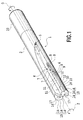
Fig. 1 is a perspective view illustrating a drilling tool according to one embodiment of the present invention; -
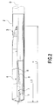
Fig. 2 is a front view illustrating the tool body of the drilling tool ofFig. 1 ; -
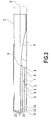
Fig. 3 is a plan view illustrating the tool body of the drilling tool ofFig. 1 ; -
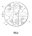
Fig. 4 is a side view illustrating the drilling tool shown inFig. 1 ; -
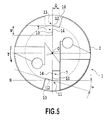
Fig. 5 is a side view illustrating the configuration of the step section of the drilling tool shown inFig. 1 ; -
Fig. 6 is a schematic view illustrating the web of the drilling tool ofFig. 1 ; -
Fig. 7 illustrates a modification example showing the web ofFig. 6 ; -
Fig. 8 is a front view illustrating a conventional drilling tool; and -
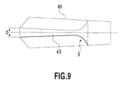
Fig. 9 is a schematic view illustrating the web of a conventional back taper drill. - The following section will describe one embodiment of a drilling tool according to the present invention with reference to
Fig. 1 to Fig. 6 . - The following section will describe one embodiment of a drilling tool according to the present invention with reference to
Fig. 1 to Fig. 6 . - A
drilling tool 1 according to the present embodiment has a shape as shown inFig. 1 in which an outer diameter has a substantially round bar-like shape. Thedrilling tool 1 includes: atool body 2 that has a cutting part and that functions as a basic section of thedrilling tool 1; and ashank 20 that is integrally formed at the rear end of thetool body 2 and that functions as a tool haft. - The
tool body 2 is formed by cemented carbide, cermet, ceramic, or ultrahigh pressure sintered body for example. As shown inFig. 1 to Fig. 4 , thetool body 2 has a substantially cylindrical shape in the outer diameter direction rotated around the axis line ○. Thistool body 2 has: achip discharge groove 4 that is formed at the outer periphery to extend from the tip end face to the rear end side; a tipend flank face 16 formed at a tip end face; and anoil hole 17 that is drilled in the interior and that is used to discharge cutting fluid. - This
tool body 2 has a cutting part tip end having an outer diameter size (i.e., diameter of the tool body 2) of 6.0mm for example. Thistool body 2 has a back tapered shape in which the outer diameter is gradually reduced from the tip end side toward the rear end side (seeFig. 6 ). InFig. 6 , the tapered shape of thetool body 2 is shown in an exaggerated manner for a description purpose. The back taper amount of thetool body 2 is set to 0.04/100 or more and 0.06/100 or less and is set to 0.05/100 for example. As shown inFig. 6 , in a part of thetool body 2 having a thick thickness (i.e., web 3), a web taper along which theweb 3 has a thickness gradually increased from the tip end side toward the rear end side is provided. Theweb 3 is formed between parts formed by the groove bottom of thechip discharge groove 4 and the sub-groove 7 that are formed to have 180-degree-rotationally-symmetrical shape to the axis line ○ of thetool body 2. The thickness of theweb 3 at the tip end of the tool body 2 (i.e., web thickness D) is set to 20% or more and 50% or less of the diameter of thetool body 2 and is set to 35% of the diameter of thetool body 2 for example. The web taper amount of thetool body 2 is set so as to secure the rigidity of thetool body 2 and is set to 0.01/100 or more and 0.50/100 or less and is preferably set to 0.05/100 or more and 0.10/100 or less (for example, is set to 0.05/100). - As shown in
Fig. 1 to Fig. 3 , thechip discharge groove 4 is composed of a straight groove that extends to draw a straight line to be substantially parallel to the axis line ○. Thechip discharge groove 4 is formed, in the vicinity of the tip end of thetool body 2, to have an arc-like cross section having center angle of about 90 degrees. Among the inner face forming thechip discharge groove 4, the inner face formed at the front side in the tool rotation direction T is formed so as to be gradually turn up in the substantially vertical direction to the inner face formed at the front side in the tool rotation direction T in a direction from the center side of thetool body 2 to the outer periphery side, as a position progresses from the tip end side of thetool body 2 to the rear end side, at a position having a fixed length from the tip end. A part corresponding to the turnup of the tool when thischip discharge groove 4 is machined (i.e., theturnup section 5 of the chip discharge groove 4) is formed so as to be turned up along theinner face 6 facing the front side of the tool rotation direction T of thechip discharge groove 4 in a direction from the center side of thetool body 2 toward the outer periphery side. At the outer side of the tool diameter direction of theinner face 6 facing the front side of the tool rotation direction T of thechip discharge groove 4, twosub-grooves 7 are formed so as to extend from the tip end side to the rear end side. Rake faces 10 are formed at the tip end side of theinner face 6 of thechip discharge groove 4, in the vicinity of thesub-grooves 7, arranged at the inner side in the tool diameter direction of thesub-grooves 7. - As shown in
Fig. 1 to Fig. 3 , thesub-grooves 7 are formed so as to extend in a straight manner to be substantially parallel to the axis line ○ until a fixed length is reached from the tip end. A part corresponding to the turnup of the tool for machining the sub-grooves 7 (i.e., theturnup sections 8 of the sub-grooves 7) are turned up in a different direction from the direction along which theturnup section 5 in thechip discharge groove 4 is turned up. Specifically, theturnup section 5 of thechip discharge groove 4 is turned up from the center side of the tool body to the outer periphery side along the inner face facing the front side of the tool rotation direction in a direction from the tip end side to the rear end side. In contrast, theturnup section 8 of the sub-groove 7 is gradually turned up in a substantially-vertical direction to the inner face 9 facing the front side in the tool rotation direction T of thesub-groove 7. - The rake face 10 is also formed at the tip end side of the inner face 9 facing the front side in the tool rotation direction T of the
sub-groove 7. Twosub-grooves 7 having a configuration as described above are provided to onechip discharge groove 4. Twosub-grooves 7 provided in onechip discharge groove 4 and twosub-grooves 7 provided in anotherchip discharge groove 4 are provided at 180 degree rotationally-symmetrical positions to the axis line ○. In the present embodiment, twosub-grooves 7 are provided in thechip discharge groove 4. However, the present invention is not limited to this. Thus, one sub-groove 7 also may be formed in thechip discharge groove 4 or three or more sub-grooves 7 also may be formed in thechip discharge groove 4. - These all
sub-grooves 7 have lengths L2 that are measured in a direction parallel to the axis line ○ and that are substantially equal. When thetool body 2 is seen from the front side in a direction orthogonal to the axis line ○, therespective sub-grooves 7 have theturnup sections 8 arranged at substantially the same positions. Therespective sub-grooves 7 have the length L2 that is shorter than the length L1 of the chip discharge groove so that theturnup sections 8 of therespective sub-grooves 7 are positioned closer to the tip end than theturnup section 5 of thechip discharge groove 4. The sub-groove 7 has the length L2 that is equal to or higher than 20% and lower than 100% of the length L1 of thechip discharge groove 4 and that is preferably 40% or more and 60% or less of the length L1 of thechip discharge groove 4 and that is set to 50% of the length L1 of thechip discharge groove 4 for example. - The
respective sub-grooves 7 have the widths W in the tool diameter direction that are substantially equal so that the width of onechip discharge groove 4 in the tool diameter direction is equally divided to three parts by twosub-grooves 7 provided in thechip discharge groove 4. Specifically, thesub-groove 7 has the width W set to be 0.2mm or more and 4.0mm or less and is preferably set to 0.4mm or more and 2.0mm or less and is set to 0.6mm for example. - As shown in
Fig. 4 , therake face 10 is configured so that therake face 10 formed in thechip discharge groove 4 and the rake faces 10 formed in the respective twosub-grooves 7 are arranged, as a result of that the three rake face are arranged to have an interval thereamong in the front-and-rear direction of the tool rotation direction T in a step-like manner to thereby form twostep sections 11. Each rake face 10 has a substantially-equal width in the tool diameter direction that is set to 0.2mm or more and 4.0mm or less corresponding to the width W of the sub-groove 7 and that is preferably set to 0.4mm or more and 2.0mm or less corresponding to the width W of the sub-groove 7 and that is set to 0.6mm for example. - As shown in
Fig. 5 , thestep section 11 is composed of the turnup face 12 turned up from therake face 10 and therake face 10 intersecting with theturnup face 12. Thisturnup face 12 provides a level difference Q between the respective rake faces 10. The level difference Q of thestep section 11 is, for example, 1.5mm when being measured in the vertical direction to therake face 10. Thisturnup face 12 is preferably inclined from thestep section 11 to the inverse side in the tool rotation direction T and to the inner side in the tool diameter direction with regard to the tangent line N drawn by the rotation trajectory circle (the circle shown by the chain line inFig. 5 ) drawn by the corner section of thestep section 11 at which theturnup face 12 intersects with therake face 10. For example, theturnup face 12 has the inclination angle α of 15 degrees to the tangent line N. The twostep sections 11 provided in onechip discharge groove 4 and twostep sections 11 provided in anotherchip discharge groove 4, having the configuration as described above, are provided at 180-degree-rotationally-symmetrical positions to the axis line ○. - Furthermore, as shown in
Fig. 4 , the cutting edges 14 are formed at the respective ridge lines at which the respective rake faces 10 intersect with the tipend flank face 16. The three neighboring cuttingedges 14 are arranged discontinuously with an interval thereamong in the front-and-rear direction of the tool rotation direction T. The threecutting edges 14 provided in a step-like manner in the tool diameter direction constitute onecutting edge 15. One pair of cuttingedges 15 is provided in a 180 degree-rotationally-symmetrical manner with respect to the axis line ○ to thereby constitute a drilling tool having two blades. These twocutting edges 15 are used to perform a drilling machining. The cutting edges 14 that are provided in a 180-degree-rotationally-symmetrical manner with respect to the axis line ○ are set to have substantially the same length. All of thecutting edge 14 have a substantially-equal length that is set so as to correspond to the width W of the sub-groove 7 in a range from 0.2mm or more to 4.0m or less and preferably in a range from 0.4mm or more to 2.0mm or less and that is set to 0.6mm for example. - The following will describe the operation of the drilling tool having the configuration as described above according to this embodiment.
- According to the
drilling tool 1 in this embodiment, the twocutting edges 15 provided to surround the axis line ○ as a center in a 180-degree-rotationally-symmetricalmannerare composed of the threecutting edges 14 that are discontinuously arranged to have an interval thereamong in the front-and-rear direction of the tool rotation direction T, respectively. Thus, therespective cutting edges 14 can be used to generate chips having a width corresponding to the length of the cutting edges 14. In other words, onecutting edge 15 is divided by twostep sections 11 to thereby provide the three cutting edges 14. Thus, instead of generating one chip having a width corresponding to the length of thecutting edge 15, three chips are generated that have a width corresponding to the length of thecutting edge 14 having an about 1/3 length of that of thecutting edge 15. Chips having a narrow width obtained through the segmentalization as described above can be easily deformed to have a curled shape quickly, thus providing a shape of superior chip controllabilily. This consequently suppresses the situation where chips are sandwitched between thetool body 2 and a workpiece to cause a damage of the cutting part section for example. This can consequently improve the accuracy of the finish surface roughness of the workpiece or the dimension accuracy and can improve the tool life. - Furthermore, when the
turnup face 12 of thestep section 11 is inclined to have the predetermined angle α to the tangent line N of the rotation trajectory circle drawn by the corner of thestep section 11 toward the rear side of the tool rotation direction T and toward the inner side of the tool diameter direction, the inner periphery end of thesubsequent cutting edge 14 provided at an immediate rear side of the corner corresponding to the outer periphery end of theprevious cutting edge 14 in the tool rotation direction T is not involved in the cutting operation (seeFig. 5 ). Thus, an eliminating the level difference Q as a result of that chips during cutting are partially welded to the inner periphery end of thesubsequent cutting edge 14, and so on, is inhibited. Thus, chips can be securely segmentalized. - Furthermore, in contrast with a conventional nicked drill in which the groove width, position, or number of the nicks is undesirably limited due to the design, the drilling tool of the present invention allows the number of the
sub-grooves 7 or the width W for example to be appropriately set depending on a required chip width. Thus, therespective cutting edges 14 can have a desired length without being limited due to a design reason. Thus, in contrast with a conventional nicked drill in which chips can be segmentalized to have a width merely reduced to about 4mm, chips generated from thedrilling tool 1 in this embodiment can be segmentalized to have a desired width and can have a further minute size. As a result, even when a deep hole having a complicated shape such as an engine block member (e. g. , a cylinder block, a journal oil supply hole) is machined for example, the resultant chips can be easily discharged to the outside, thus preventing chips from remaining. - Furthermore, in contrast with a conventional nicked drill, no operation is required to repeatedly machine to form the nick whenever the cutting edge is grinded, thus providing a superior work efficiency.
- Furthermore, the three
cutting edges 14 constituting thecutting edge 15 and the threecutting edges 14 constituting anothercutting edge 15 are mutually provided at rotationally-symmetrical positions to the axis line ○. The cutting edges 14 provided at 180 degree-rotationally-symmetrical positions to the axis line ○ have substantially the same length. Thus, cutting resistance is applied to therespective cutting edges 14 in a balanced and uniform manner to thereby apply a uniform cutting force to therespective cutting edges 14 during cutting. As a result, the tool is rotated stably to thereby suppress vibration from occurring. Thus, the machining hole has an improved machining accuracy (e.g., hole position accuracy, hole diameter size, roundness, straightness, finish surface roughness). - All of the cutting edges 14 having substantially the same length mean that chips generated through the
respective cutting edges 14 have a uniform width or deformation. Thus, a part of the chips can be prevented from having a long length, thus allowing chips to be stably machined through the respective cutting edges 14. - In this case, the
drilling tool 1 according to the present embodiment is formed so that theturnup section 5 of the sub-groove 7 is differently formed from theturnup section 5 of thechip discharge groove 4. Specifically, theturnup section 5 of the sub-groove 7 is formed to be gradually turned up in a direction substantially vertical to the inner face 9 facing to the front side in the tool rotation direction T of thesub-groove 7. Thus, when chips reach theturnup section 8 of the sub-groove 7, the chips will be pushed to the interior of thechip discharge groove 4. Thus, thedrilling tool 1 has a superior chip discharge property by which the chipping due to sandwitched chips, a defective tool, or a damaged machining surface for example can be avoided. Thus, the tool life is extended and the machining accuracy is improved. - On the other hand, in the case of the
conventional drilling tool 30 as shown inFig. 8 in which theturnup section 38 of the sub-groove 37 is configured as in theturnup section 5 of thechip discharge groove 4 so as to be turned up from the center of thetool body 2 to the outer periphery side along the inner face 9 facing the front side in the tool rotation direction T and in a direction from the tip end side toward the rear end side, chips reaching theturnup section 38 of the sub-groove 37 are pushed toward the outer periphery side of thetool body 2 in theturnup section 38 of the sub-groove 37. This causes a possibility where chips may be sandwitched in a narrow space between theturnup section 38 of the sub-groove 37 positioned at the outermost side of the tool diameter direction and the workpiece. - Furthermore, the
sub-groove 7 of thedrilling tool 1 according to the present embodiment has the length L2 that is shorter than the length L1 of thechip discharge groove 4. Thus, when compared with theconventional drilling tool 30 including the sub-groove 37 having the same length as that of the chip discharge groove 4 (with reference toFig. 8 ), thedrilling tool 1 has an increased thickness at the rear end side of thetool body 2, thus providing a higher tool rigidity. Therefore, even when the cutting edge having the shape as described above is applied in a long tool such as a gun drill used for a deep hole machining, a sufficient tool rigidity is secured, thus suppressing chatter vibration or a broken tool. - Furthermore, the sub-groove 7 having the length L2 shorter than the length L1 of the
chip discharge groove 4 reduces the time required to machine thesub-groove 7. This provides a shorter manufacture time of thedrilling tool 1 when compared with theconventional drilling tool 30 having the sub-groove 37 having the same length as that of thechip discharge groove 4, thus reducing the manufacturing cost. - As described above, even when the sub-groove 7 has the length L2 shorter than the length L1 of the
chip discharge groove 4, a space for discharging chips is sufficiently secured because the length L1 of thechip discharge groove 4 is set to be long as in the conventional design. Furthermore, chips reaching theturnup section 8 of the sub-groove 7 will be pushed along the turnup direction of theturnup section 8 in the sub-groove 7 toward the interior of thechip discharge groove 4. Thus, thedrilling tool 1 can provide a superior chip discharge property. - Furthermore, the
drilling tool 1 according to this embodiment has a web tapered structure in which the thickness of theweb 3 is gradually increased from the tip end side of thetool body 2 to the rear end side, thus providing improved tool rigidity more than in the conventional case. - When the
tool body 2 having a back tapered structure from the viewpoint of improving the tool rigidity has a web tapered structure as described above, the rear end side of thetool body 2 is prevented from having an increased cross-sectional area of thechip discharge groove 4, thus undesirably causing thechip discharge groove 4 to have a smaller cross-sectional area than that of the tip end side of thetool body 2. However, according to thedrilling tool 1 of the present embodiment, the step-like cutting edge 14 can be used to segmentalize chips with good chip controllability. Thus, even when thechip discharge groove 4 does not have a large cross-sectional area, chips can be prevented from clogging the rear end side of thetool body 2 or being sandwitched between thetool body 2 and the workpiece. Thus, thetool body 2 having a back tapered structure can have a web tapered structure, thus improving the tool rigidity. - On the other hand, in the case of the conventional
back taper drill 40 as shown inFig. 9 , a chip discharge groove must have a certain level of a cross-sectional area in order to securely discharge chips. Thus, theweb 43 is configured so that theweb 43 is formed to correspond to the back taper to have a thickness decreased from the tip end side of thetool body 2 toward the rear end side. This means a possibility where an increased number ofsub-grooves 37 causes a declined tool rigidity. - In the
drilling tool 1 of the present embodiment, a web tapered structure was used in thetool body 2 in which theweb 3 has a thickness increased from the tip end side toward the rear end side. However, another configuration as shown inFig. 7 also may be used where the web 3' has substantially the same thickness that is substantially the same as the thickness of the web thickness D over the entire length of thetool body 2. In this case, the tool rigidity is improved than in the case of the conventionalback taper drill 40 in which theweb 43 has a thickness gradually decreased from the tip end side of thetool body 2 to the rear end side. Furthermore, the drilling tool ofFig. 7 provides a larger cross-sectional area of thechip discharge groove 4 than in the case of thedrilling tool 1 in which theweb 3 has a thickness increased from the tip end side of thetool body 2 toward the rear end side, thus providing a proportionally-improved chip discharge property. - Furthermore, in the
drilling tool 1 according to the present embodiment, the number of the sub-grooves 7 is not particularly limited and can be set to an arbitrary number. In the case of thedrilling tool 1 having the same diameter, an increase in the number of thesub-grooves 7 causes an increase in the number of the cutting edges 14, which causes the reduction in the length of one blade involved in a cutting operation. Thus, chips obtained through each cuttingedge 14 have a reduced width. Specifically, chips are divided in the width direction in the number corresponding to the number of thesub-grooves 7. Thus, a higher number ofsub-grooves 7 is preferred from the viewpoint of chip segmentalization. For example, chip segmentalized to have a width of about 1 to 4mm can be obtained by allowing onechip discharge groove 4 to include two to foursub-grooves 7 in the tool having a diameter of 12mm and by allowing onechip discharge groove 4 to include three to fivesub-grooves 7 in the tool having a diameter of 16mm. - Furthermore, in the
drilling tool 1 according to the present embodiment, therespective sub-grooves 7 have a substantially equal width W, thechip discharge groove 4 has a width in the tool diameter direction that is equally divided to three parts by twosub-grooves 7, and all of the cutting edges 14 have substantially the same length. However, another configuration also may be used, for example, in which the width W of the sub-groove is equally divided to four or more parts or the respective sub-grooves also may have different widths so that therespective cutting edges 14 can have an arbitrary length depending on an intended use or use conditions. The reduction of the width W of the sub-groove 7 causes an increase in the number of thesub-grooves 7 that can be formed in onechip discharge groove 4 causes an increase of the number of the cutting edges 14. Thus, the length of one blade is reduced. Thus, the sub-groove 7 having a narrower width W is preferred from the viewpoint of chip segmentalization. - Furthermore, the
drilling tool 1 according to the present embodiment is configured so that all of thesub-grooves 7 have the same length L. However, another configuration also may be used in which therespective sub-grooves 7 adjacent to each other in onechip discharge groove 4 have lengths set to be gradually shorter from the inner side in the tool diameter direction toward the outer side. This configuration provides a further-improved tool rigidity. - Furthermore, the
drilling tool 1 according to the present embodiment is configured so that theturnup section 8 of the sub-groove 7 is gradually turned up from the tip end side toward the rear end side in a direction substantially vertical to the inner face 9 facing the front side in the tool rotation direction T of thesub-groove 7. However, theturnup section 8 of the sub-groove 7 also can be turned up in a different direction other than the above direction. For example, theturnup section 8 of the sub-groove 7 also may be formed to be gradually turned up in a direction substantially vertical to theinner face 6 facing the front side in the tool rotation direction T of thechip discharge groove 4. - Furthermore, the
drilling tool 1 according to the present embodiment is configured so that thestep section 11 has the level difference Q of 0.5mm and the turnup face 12 has the inclination angle α of 15 degrees. However, the drilling tool of the present invention also can be configured so that the level difference Q of thestep section 11 and the inclination angle α of theturnup face 12 are not particularly limited and can be set to an arbitrary value. Thisstep section 11 preferably has the level difference Q that is 0. 5mm or more and 2.0mm or less and that is advantageously 0.25mm or more and 1.0mm or less. The reason is that the level difference Q smaller than 0.15mm causes the level difference Q to be eliminated due to a weld deposit caused by a cutting operation, thus causing a situation where chips on therespective cutting edges 14 may be undesirably connected without being divided and thus chips having a wide width may be generated. Another reason is that the level difference Q larger than 2.0mm may undesirably cause thetool body 2 to have a reduced cross-sectional area, thus deteriorating the tool rigidity. The inclination angle α of theturnup face 12 is preferably 0<α≤45 and is preferably 2.0<α≤20. When theturnup face 12 is inclined to the front side in the tool rotation direction T to the tangent line N of the rotation trajectory circle drawn by the corner of thestep section 11, the inner periphery end of thesubsequent cutting edge 14 is also subjected to a cutting operation. Thus, a situation may be caused where chips on therespective cutting edges 14 are connected without being divided and chips having a wide width are generated. When the angle formed by therake face 10 and the turnup face 12 is 90 degrees and the inclination angle α of the turnup face 12 to the tangent line N is 0 degree, chips may be partially welded to the inner periphery end of thesubsequent cutting edge 14, and so on, due to a cutting operation, causing a possibility where the chips at the respective cutting edges may be connected without being divided. The inclination angle α of the turnup face 12 exceeding 45 degrees causes a risk where the drilling tool of the present invention cannot maintain the strength at the ridge line at which therake face 10 intersects with the turnup face. - Furthermore, the
drilling tool 1 according to the present embodiment is a two-blade drill including the two cutting edges 15. However, the drilling tool of the present invention also may be one-blade drill or a three-blade drill. When the drilling tool of the present invention has there blades, the cutting edges 14 constituting the respective threecutting edges 15 are arranged to be 120-degree-rotationally-symmetrical (three time symmetrical) to the axis line ○, thus allowing the tool to rotate stably. This consequently suppresses vibration from occurring, thus further improving the machining surface quality and the dimension accuracy for example. - Furthermore, a drilling tool has been illustratively described in order to describe the drilling tool of the present invention. However, the drilling tool of the present invention is not limited to this. The present invention also can be used for various drilling tools including general solid drill, blade drill, top solid drill, core drill, reamer, and boring cutter for example. Furthermore, the outer periphery of the
tool body 2 also may include a margin from the viewpoint of improving the finish surface roughness or also may include a guide pad form the viewpoint of improving the guide property. - A typical embodiment of the present invention has been described as described above. However, the present embodiment can be subjected to various modifications and can be subjected to substitution or change so long as the substitution or change does not deviate from the intention and the scope of the present invention defined by the claims of this application.
Claims (7)
- A drilling tool, comprising:a tool body having an outer shape having a substantially cylindrical shape rotated around an axis line;a chip discharge groove formed in an outer periphery of the tool body to extend from a tip end face of the tool body to a rear end side;at least one sub-groove that is formed at an inner face facing a front side in a tool rotation direction of the chip discharge groove and that is formed to extend from a tip end face of the tool body to a rear end side;a rake face formed at an inner face facing the front side in the tool rotation direction of the chip discharge groove and the at least one sub-groove, respectively;a tip end flank face formed at a tip end face of the tool body; anda cutting edge formed at a ridge line at which the tip end flank face intersects with the rake face,wherein, the inner face facing the front side in the tool rotation direction of the chip discharge groove is formed to have a step-like shape having at least one step section by the rake face, anda turnup section at the rear end side of the sub-groove is turned up in a different direction from the direction along which the turn up section at the rear end side of the chip discharge groove is turned up.
- The drilling tool according to claim 1, wherein the turnup section of the chip discharge groove is gradually turned up along an inner face facing the front side in the tool rotation direction from the tip end side toward the rear end side in a direction from the center side of the tool body to the outer periphery side.
- The drilling tool according to claim 1 or 2, wherein the turnup section of the sub-groove is gradually turned up from the tip end side to the rear end side in a direction substantially vertical to the inner face facing the front side in the tool rotation direction of the sub-groove.
- The drilling tool according to any one of claims 1 to 3, wherein the sub-groove has a shorter length than a length of the chip discharge groove.
- The drilling tool according to any one of claims 1 to 4, wherein: the tool body has a back tapered structure in which an outer diameter is gradually reduced from the tip end side to the rear end side and a web at the rear end side of the tool body has a thickness equal to or higher than a thickness of a web thickness of the tool body.
- The drilling tool according to claim 5, wherein the tool body has a web tapered structure in which the web has a thickness gradually increased from the tip end side toward the rear end side.
- The drilling tool according to claim 5, wherein the web has substantially the same thickness from the tip end side of the tool body toward the rear end side.
Applications Claiming Priority (2)
| Application Number | Priority Date | Filing Date | Title |
|---|---|---|---|
| JP2009140447 | 2009-06-11 | ||
| PCT/JP2010/059542 WO2010143595A1 (en) | 2009-06-11 | 2010-06-04 | Drilling tool |
Publications (3)
| Publication Number | Publication Date |
|---|---|
| EP2441543A1 true EP2441543A1 (en) | 2012-04-18 |
| EP2441543A4 EP2441543A4 (en) | 2017-04-05 |
| EP2441543B1 EP2441543B1 (en) | 2018-10-03 |
Family
ID=43308850
Family Applications (1)
| Application Number | Title | Priority Date | Filing Date |
|---|---|---|---|
| EP10786126.2A Not-in-force EP2441543B1 (en) | 2009-06-11 | 2010-06-04 | Drilling tool |
Country Status (9)
| Country | Link |
|---|---|
| US (1) | US9028179B2 (en) |
| EP (1) | EP2441543B1 (en) |
| JP (1) | JP4919182B2 (en) |
| KR (1) | KR101288439B1 (en) |
| CN (1) | CN102802851B (en) |
| BR (1) | BRPI1010618A2 (en) |
| CA (1) | CA2763051C (en) |
| RU (1) | RU2487783C1 (en) |
| WO (1) | WO2010143595A1 (en) |
Cited By (1)
| Publication number | Priority date | Publication date | Assignee | Title |
|---|---|---|---|---|
| CN115335169A (en) * | 2020-03-23 | 2022-11-11 | 联合材料公司 | Rotary cutting tool |
Families Citing this family (19)
| Publication number | Priority date | Publication date | Assignee | Title |
|---|---|---|---|---|
| DE102010041840A1 (en) * | 2010-10-01 | 2012-04-05 | Bayerische Motoren Werke Aktiengesellschaft | Method for producing a ventilation bore in a bearing block of a crankcase of a reciprocating internal combustion engine |
| US9232952B2 (en) | 2012-04-16 | 2016-01-12 | Medtronic Ps Medical, Inc. | Surgical bur with non-paired flutes |
| JP5584790B1 (en) * | 2013-02-27 | 2014-09-03 | 株式会社タンガロイ | Drill tip structure and drill and drill head having the tip structure |
| US9883873B2 (en) | 2013-07-17 | 2018-02-06 | Medtronic Ps Medical, Inc. | Surgical burs with geometries having non-drifting and soft tissue protective characteristics |
| CN105451918B (en) * | 2013-08-26 | 2018-08-14 | 京瓷株式会社 | Drill bit and used the drill bit machined object manufacturing method |
| US10335166B2 (en) | 2014-04-16 | 2019-07-02 | Medtronics Ps Medical, Inc. | Surgical burs with decoupled rake surfaces and corresponding axial and radial rake angles |
| JP6223316B2 (en) * | 2014-11-13 | 2017-11-01 | ジヤトコ株式会社 | Cutting equipment |
| TWI508804B (en) * | 2014-12-23 | 2015-11-21 | 張新添 | Screw feed cutter |
| CN105798358A (en) * | 2014-12-27 | 2016-07-27 | 汪风珍 | Toothed drill |
| CN105983718A (en) * | 2015-02-16 | 2016-10-05 | 汪风珍 | Drill bit |
| US9955981B2 (en) | 2015-03-31 | 2018-05-01 | Medtronic Xomed, Inc | Surgical burs with localized auxiliary flutes |
| US10265082B2 (en) | 2015-08-31 | 2019-04-23 | Medtronic Ps Medical, Inc. | Surgical burs |
| JP5967328B1 (en) * | 2016-03-28 | 2016-08-10 | 株式会社タンガロイ | Drilling tool |
| DE102017111630A1 (en) * | 2017-05-29 | 2018-11-29 | Botek Präzisionsbohrtechnik Gmbh | Single lip deep hole drills with stepped rake surface |
| CN107081456A (en) * | 2017-06-19 | 2017-08-22 | 沈阳飞机工业(集团)有限公司 | A kind of pull-type broad of deep hole processing |
| JP7164101B2 (en) * | 2018-02-06 | 2022-11-01 | 国立大学法人東海国立大学機構 | Drills and drilling equipment |
| DE102018114138A1 (en) * | 2018-06-13 | 2019-12-19 | Botek Präzisionsbohrtechnik Gmbh | Deep hole drill with several chip formers and troughs in the rake face |
| CN109227062A (en) * | 2018-09-21 | 2019-01-18 | 上海名古屋精密工具股份有限公司 | A kind of production method of cylindrical cuts cutter |
| WO2024176372A1 (en) * | 2023-02-22 | 2024-08-29 | 三菱マテリアル株式会社 | Drill |
Family Cites Families (32)
| Publication number | Priority date | Publication date | Assignee | Title |
|---|---|---|---|---|
| US867639A (en) * | 1906-05-21 | 1907-10-08 | George J Bragg | Twist-drill. |
| US1407546A (en) * | 1919-10-15 | 1922-02-21 | Joseph Felix Alexander | Twist drill |
| US2201159A (en) * | 1937-05-10 | 1940-05-21 | Philplug Products Ltd | Boring or drilling tool |
| US2646701A (en) * | 1949-12-27 | 1953-07-28 | Peter A Letien | Stepped edge cutting tool |
| SU517411A1 (en) * | 1972-10-10 | 1976-06-15 | Московское Ордена Ленина И Ордена Трудового Красного Знамени Высшее Техническое Училище Имени Н.Э. Баумана | Mnogoperovoe drill |
| JPS5014097U (en) * | 1973-05-31 | 1975-02-14 | ||
| JPS53199B2 (en) | 1973-06-11 | 1978-01-06 | ||
| JPS562447Y2 (en) * | 1973-12-24 | 1981-01-20 | ||
| US4080093A (en) * | 1974-11-18 | 1978-03-21 | Hartmetallwerkzeugfabrik Andreas Maier Kg | Drill for electronic conductor plates |
| JPS5923925B2 (en) * | 1975-12-29 | 1984-06-06 | カブシキガイシヤ ササクラキカイセイサクシヨ | Drill reamer |
| SU663501A2 (en) * | 1977-12-26 | 1979-05-25 | Минское Специальное Конструкторское Бюро Автоматических Линий | Twist drill |
| JPS6042509U (en) * | 1983-08-29 | 1985-03-26 | 住友電気工業株式会社 | gun drill |
| JPS6074904A (en) | 1983-09-28 | 1985-04-27 | Toyo Electric Mfg Co Ltd | Controller for electric car |
| JPS6074904U (en) * | 1983-10-28 | 1985-05-25 | 三菱マテリアル株式会社 | gun drill |
| JPS6442815A (en) | 1987-08-10 | 1989-02-15 | Mitsubishi Electric Corp | Compound semiconductor crystal growth method |
| JPH0632253Y2 (en) * | 1987-09-05 | 1994-08-24 | 大見工業株式会社 | Burnishing drill |
| DE3730378A1 (en) * | 1987-09-10 | 1989-03-23 | Micro Crystal Ag | CUTTING TOOL, ESPECIALLY DRILLING AND / OR MILLING |
| JP2523616Y2 (en) * | 1989-08-31 | 1997-01-29 | 東芝タンガロイ株式会社 | Drilling tool |
| JPH03196908A (en) * | 1989-12-22 | 1991-08-28 | Masahiro Morita | Drill |
| JPH0691418A (en) * | 1991-06-04 | 1994-04-05 | Ishikura Kogyo Kk | Burnishing drill |
| BR9607878A (en) * | 1995-03-30 | 1999-11-30 | Vilab Ag | Snipping tool. |
| JPH08323541A (en) * | 1995-05-26 | 1996-12-10 | Fuji Seiko Kk | Reamer with chip breaker |
| JP3766473B2 (en) * | 1996-07-12 | 2006-04-12 | 住友電気工業株式会社 | Step drill |
| IL120948A0 (en) | 1997-05-29 | 1997-09-30 | Iscar Ltd | Cutting tool assembly |
| US20030185640A1 (en) * | 2002-03-27 | 2003-10-02 | Eiji Ito | Multiple rake drill bits |
| JP3720010B2 (en) * | 2002-10-02 | 2005-11-24 | オーエスジー株式会社 | Deep hole drill |
| DE102005005982A1 (en) * | 2005-02-09 | 2006-08-17 | Günther & Co GmbH | Gun drills |
| JP2007050477A (en) | 2005-08-18 | 2007-03-01 | Mitsubishi Materials Kobe Tools Corp | Drill with extra-high pressure sintered body chip |
| JP2009101460A (en) * | 2007-10-23 | 2009-05-14 | Omi Kogyo Co Ltd | Cutting tools |
| JP4941356B2 (en) | 2008-02-28 | 2012-05-30 | 株式会社タンガロイ | Drilling tool |
| CN201223962Y (en) * | 2008-07-21 | 2009-04-22 | 哈尔滨汽轮机厂有限责任公司 | Step chip dividing groove deep hole drill |
| JP5413888B2 (en) | 2009-04-24 | 2014-02-12 | 株式会社タンガロイ | Drilling tool |
-
2010
- 2010-06-04 RU RU2011150265/02A patent/RU2487783C1/en not_active IP Right Cessation
- 2010-06-04 EP EP10786126.2A patent/EP2441543B1/en not_active Not-in-force
- 2010-06-04 CA CA2763051A patent/CA2763051C/en not_active Expired - Fee Related
- 2010-06-04 JP JP2011518514A patent/JP4919182B2/en not_active Expired - Fee Related
- 2010-06-04 CN CN201080025755.7A patent/CN102802851B/en not_active Expired - Fee Related
- 2010-06-04 KR KR20117029154A patent/KR101288439B1/en not_active Expired - Fee Related
- 2010-06-04 WO PCT/JP2010/059542 patent/WO2010143595A1/en not_active Ceased
- 2010-06-04 BR BRPI1010618A patent/BRPI1010618A2/en not_active IP Right Cessation
-
2011
- 2011-11-18 US US13/300,423 patent/US9028179B2/en not_active Expired - Fee Related
Cited By (2)
| Publication number | Priority date | Publication date | Assignee | Title |
|---|---|---|---|---|
| CN115335169A (en) * | 2020-03-23 | 2022-11-11 | 联合材料公司 | Rotary cutting tool |
| US12599975B2 (en) | 2020-03-23 | 2026-04-14 | A.L.M.T. Corp. | Rotary cutting tool |
Also Published As
| Publication number | Publication date |
|---|---|
| US20120063860A1 (en) | 2012-03-15 |
| RU2487783C1 (en) | 2013-07-20 |
| CN102802851A (en) | 2012-11-28 |
| WO2010143595A1 (en) | 2010-12-16 |
| JP4919182B2 (en) | 2012-04-18 |
| BRPI1010618A2 (en) | 2016-03-15 |
| KR101288439B1 (en) | 2013-07-26 |
| EP2441543B1 (en) | 2018-10-03 |
| US9028179B2 (en) | 2015-05-12 |
| CA2763051C (en) | 2013-05-28 |
| JPWO2010143595A1 (en) | 2012-11-22 |
| CA2763051A1 (en) | 2010-12-16 |
| EP2441543A4 (en) | 2017-04-05 |
| CN102802851B (en) | 2014-11-19 |
| KR20120016267A (en) | 2012-02-23 |
Similar Documents
| Publication | Publication Date | Title |
|---|---|---|
| EP2441543B1 (en) | Drilling tool | |
| EP2106868B1 (en) | Insert for drill and indexable insert drill | |
| JP6853442B2 (en) | Cutting inserts and cutting tools with replaceable cutting edges | |
| US8807882B2 (en) | Face milling cutter | |
| EP2065111B1 (en) | Rotary cutting tool | |
| JP6086179B1 (en) | Replaceable blade cutting tool and insert | |
| EP3597338B1 (en) | Ball end mill | |
| US10926344B2 (en) | Taper reamer | |
| US10850335B2 (en) | Cutting insert and cutting edge-interchangeable rotary cutting tool | |
| KR20190034266A (en) | Cutting inserts and cutting blades | |
| CN108290233B (en) | Indexable insert type rotary cutting tool and insert | |
| JP7481617B2 (en) | Processing method and mold manufacturing method | |
| WO2018003684A1 (en) | Cutting insert and replaceable cutting edge rotary cutting tool | |
| JP4941356B2 (en) | Drilling tool | |
| EP3812070B1 (en) | End mill | |
| JP2008173727A (en) | Drill | |
| JP2018043321A (en) | Cutting insert and cutting edge exchangeable cutting tool | |
| WO2025105312A1 (en) | Drill | |
| WO2025105294A1 (en) | Drill | |
| JPH10180514A (en) | Drilling tool |
Legal Events
| Date | Code | Title | Description |
|---|---|---|---|
| PUAI | Public reference made under article 153(3) epc to a published international application that has entered the european phase |
Free format text: ORIGINAL CODE: 0009012 |
|
| 17P | Request for examination filed |
Effective date: 20111214 |
|
| AK | Designated contracting states |
Kind code of ref document: A1 Designated state(s): AL AT BE BG CH CY CZ DE DK EE ES FI FR GB GR HR HU IE IS IT LI LT LU LV MC MK MT NL NO PL PT RO SE SI SK SM TR |
|
| DAX | Request for extension of the european patent (deleted) | ||
| RA4 | Supplementary search report drawn up and despatched (corrected) |
Effective date: 20170308 |
|
| RIC1 | Information provided on ipc code assigned before grant |
Ipc: B23B 51/00 20060101AFI20170302BHEP |
|
| GRAP | Despatch of communication of intention to grant a patent |
Free format text: ORIGINAL CODE: EPIDOSNIGR1 |
|
| STAA | Information on the status of an ep patent application or granted ep patent |
Free format text: STATUS: GRANT OF PATENT IS INTENDED |
|
| INTG | Intention to grant announced |
Effective date: 20180420 |
|
| RIN1 | Information on inventor provided before grant (corrected) |
Inventor name: NISIKAWA, KOJI Inventor name: WADA, KENGO |
|
| GRAS | Grant fee paid |
Free format text: ORIGINAL CODE: EPIDOSNIGR3 |
|
| GRAA | (expected) grant |
Free format text: ORIGINAL CODE: 0009210 |
|
| STAA | Information on the status of an ep patent application or granted ep patent |
Free format text: STATUS: THE PATENT HAS BEEN GRANTED |
|
| AK | Designated contracting states |
Kind code of ref document: B1 Designated state(s): AL AT BE BG CH CY CZ DE DK EE ES FI FR GB GR HR HU IE IS IT LI LT LU LV MC MK MT NL NO PL PT RO SE SI SK SM TR |
|
| REG | Reference to a national code |
Ref country code: GB Ref legal event code: FG4D |
|
| REG | Reference to a national code |
Ref country code: CH Ref legal event code: EP Ref country code: AT Ref legal event code: REF Ref document number: 1048076 Country of ref document: AT Kind code of ref document: T Effective date: 20181015 |
|
| REG | Reference to a national code |
Ref country code: IE Ref legal event code: FG4D Ref country code: DE Ref legal event code: R096 Ref document number: 602010054079 Country of ref document: DE |
|
| REG | Reference to a national code |
Ref country code: NL Ref legal event code: MP Effective date: 20181003 |
|
| REG | Reference to a national code |
Ref country code: LT Ref legal event code: MG4D |
|
| REG | Reference to a national code |
Ref country code: AT Ref legal event code: MK05 Ref document number: 1048076 Country of ref document: AT Kind code of ref document: T Effective date: 20181003 |
|
| PG25 | Lapsed in a contracting state [announced via postgrant information from national office to epo] |
Ref country code: NL Free format text: LAPSE BECAUSE OF FAILURE TO SUBMIT A TRANSLATION OF THE DESCRIPTION OR TO PAY THE FEE WITHIN THE PRESCRIBED TIME-LIMIT Effective date: 20181003 |
|
| PG25 | Lapsed in a contracting state [announced via postgrant information from national office to epo] |
Ref country code: CZ Free format text: LAPSE BECAUSE OF FAILURE TO SUBMIT A TRANSLATION OF THE DESCRIPTION OR TO PAY THE FEE WITHIN THE PRESCRIBED TIME-LIMIT Effective date: 20181003 Ref country code: ES Free format text: LAPSE BECAUSE OF FAILURE TO SUBMIT A TRANSLATION OF THE DESCRIPTION OR TO PAY THE FEE WITHIN THE PRESCRIBED TIME-LIMIT Effective date: 20181003 Ref country code: IS Free format text: LAPSE BECAUSE OF FAILURE TO SUBMIT A TRANSLATION OF THE DESCRIPTION OR TO PAY THE FEE WITHIN THE PRESCRIBED TIME-LIMIT Effective date: 20190203 Ref country code: NO Free format text: LAPSE BECAUSE OF FAILURE TO SUBMIT A TRANSLATION OF THE DESCRIPTION OR TO PAY THE FEE WITHIN THE PRESCRIBED TIME-LIMIT Effective date: 20190103 Ref country code: AT Free format text: LAPSE BECAUSE OF FAILURE TO SUBMIT A TRANSLATION OF THE DESCRIPTION OR TO PAY THE FEE WITHIN THE PRESCRIBED TIME-LIMIT Effective date: 20181003 Ref country code: HR Free format text: LAPSE BECAUSE OF FAILURE TO SUBMIT A TRANSLATION OF THE DESCRIPTION OR TO PAY THE FEE WITHIN THE PRESCRIBED TIME-LIMIT Effective date: 20181003 Ref country code: PL Free format text: LAPSE BECAUSE OF FAILURE TO SUBMIT A TRANSLATION OF THE DESCRIPTION OR TO PAY THE FEE WITHIN THE PRESCRIBED TIME-LIMIT Effective date: 20181003 Ref country code: LT Free format text: LAPSE BECAUSE OF FAILURE TO SUBMIT A TRANSLATION OF THE DESCRIPTION OR TO PAY THE FEE WITHIN THE PRESCRIBED TIME-LIMIT Effective date: 20181003 Ref country code: FI Free format text: LAPSE BECAUSE OF FAILURE TO SUBMIT A TRANSLATION OF THE DESCRIPTION OR TO PAY THE FEE WITHIN THE PRESCRIBED TIME-LIMIT Effective date: 20181003 Ref country code: BG Free format text: LAPSE BECAUSE OF FAILURE TO SUBMIT A TRANSLATION OF THE DESCRIPTION OR TO PAY THE FEE WITHIN THE PRESCRIBED TIME-LIMIT Effective date: 20190103 Ref country code: LV Free format text: LAPSE BECAUSE OF FAILURE TO SUBMIT A TRANSLATION OF THE DESCRIPTION OR TO PAY THE FEE WITHIN THE PRESCRIBED TIME-LIMIT Effective date: 20181003 |
|
| PG25 | Lapsed in a contracting state [announced via postgrant information from national office to epo] |
Ref country code: AL Free format text: LAPSE BECAUSE OF FAILURE TO SUBMIT A TRANSLATION OF THE DESCRIPTION OR TO PAY THE FEE WITHIN THE PRESCRIBED TIME-LIMIT Effective date: 20181003 Ref country code: SE Free format text: LAPSE BECAUSE OF FAILURE TO SUBMIT A TRANSLATION OF THE DESCRIPTION OR TO PAY THE FEE WITHIN THE PRESCRIBED TIME-LIMIT Effective date: 20181003 Ref country code: PT Free format text: LAPSE BECAUSE OF FAILURE TO SUBMIT A TRANSLATION OF THE DESCRIPTION OR TO PAY THE FEE WITHIN THE PRESCRIBED TIME-LIMIT Effective date: 20190203 Ref country code: GR Free format text: LAPSE BECAUSE OF FAILURE TO SUBMIT A TRANSLATION OF THE DESCRIPTION OR TO PAY THE FEE WITHIN THE PRESCRIBED TIME-LIMIT Effective date: 20190104 |
|
| REG | Reference to a national code |
Ref country code: DE Ref legal event code: R097 Ref document number: 602010054079 Country of ref document: DE |
|
| PG25 | Lapsed in a contracting state [announced via postgrant information from national office to epo] |
Ref country code: IT Free format text: LAPSE BECAUSE OF FAILURE TO SUBMIT A TRANSLATION OF THE DESCRIPTION OR TO PAY THE FEE WITHIN THE PRESCRIBED TIME-LIMIT Effective date: 20181003 Ref country code: DK Free format text: LAPSE BECAUSE OF FAILURE TO SUBMIT A TRANSLATION OF THE DESCRIPTION OR TO PAY THE FEE WITHIN THE PRESCRIBED TIME-LIMIT Effective date: 20181003 |
|
| PLBE | No opposition filed within time limit |
Free format text: ORIGINAL CODE: 0009261 |
|
| STAA | Information on the status of an ep patent application or granted ep patent |
Free format text: STATUS: NO OPPOSITION FILED WITHIN TIME LIMIT |
|
| PG25 | Lapsed in a contracting state [announced via postgrant information from national office to epo] |
Ref country code: EE Free format text: LAPSE BECAUSE OF FAILURE TO SUBMIT A TRANSLATION OF THE DESCRIPTION OR TO PAY THE FEE WITHIN THE PRESCRIBED TIME-LIMIT Effective date: 20181003 Ref country code: SM Free format text: LAPSE BECAUSE OF FAILURE TO SUBMIT A TRANSLATION OF THE DESCRIPTION OR TO PAY THE FEE WITHIN THE PRESCRIBED TIME-LIMIT Effective date: 20181003 Ref country code: RO Free format text: LAPSE BECAUSE OF FAILURE TO SUBMIT A TRANSLATION OF THE DESCRIPTION OR TO PAY THE FEE WITHIN THE PRESCRIBED TIME-LIMIT Effective date: 20181003 Ref country code: SK Free format text: LAPSE BECAUSE OF FAILURE TO SUBMIT A TRANSLATION OF THE DESCRIPTION OR TO PAY THE FEE WITHIN THE PRESCRIBED TIME-LIMIT Effective date: 20181003 |
|
| 26N | No opposition filed |
Effective date: 20190704 |
|
| PG25 | Lapsed in a contracting state [announced via postgrant information from national office to epo] |
Ref country code: SI Free format text: LAPSE BECAUSE OF FAILURE TO SUBMIT A TRANSLATION OF THE DESCRIPTION OR TO PAY THE FEE WITHIN THE PRESCRIBED TIME-LIMIT Effective date: 20181003 |
|
| PG25 | Lapsed in a contracting state [announced via postgrant information from national office to epo] |
Ref country code: MC Free format text: LAPSE BECAUSE OF FAILURE TO SUBMIT A TRANSLATION OF THE DESCRIPTION OR TO PAY THE FEE WITHIN THE PRESCRIBED TIME-LIMIT Effective date: 20181003 |
|
| REG | Reference to a national code |
Ref country code: CH Ref legal event code: PL |
|
| REG | Reference to a national code |
Ref country code: BE Ref legal event code: MM Effective date: 20190630 |
|
| PG25 | Lapsed in a contracting state [announced via postgrant information from national office to epo] |
Ref country code: TR Free format text: LAPSE BECAUSE OF FAILURE TO SUBMIT A TRANSLATION OF THE DESCRIPTION OR TO PAY THE FEE WITHIN THE PRESCRIBED TIME-LIMIT Effective date: 20181003 |
|
| PG25 | Lapsed in a contracting state [announced via postgrant information from national office to epo] |
Ref country code: IE Free format text: LAPSE BECAUSE OF NON-PAYMENT OF DUE FEES Effective date: 20190604 |
|
| PG25 | Lapsed in a contracting state [announced via postgrant information from national office to epo] |
Ref country code: BE Free format text: LAPSE BECAUSE OF NON-PAYMENT OF DUE FEES Effective date: 20190630 Ref country code: CH Free format text: LAPSE BECAUSE OF NON-PAYMENT OF DUE FEES Effective date: 20190630 Ref country code: LU Free format text: LAPSE BECAUSE OF NON-PAYMENT OF DUE FEES Effective date: 20190604 Ref country code: LI Free format text: LAPSE BECAUSE OF NON-PAYMENT OF DUE FEES Effective date: 20190630 |
|
| PG25 | Lapsed in a contracting state [announced via postgrant information from national office to epo] |
Ref country code: CY Free format text: LAPSE BECAUSE OF FAILURE TO SUBMIT A TRANSLATION OF THE DESCRIPTION OR TO PAY THE FEE WITHIN THE PRESCRIBED TIME-LIMIT Effective date: 20181003 |
|
| PG25 | Lapsed in a contracting state [announced via postgrant information from national office to epo] |
Ref country code: HU Free format text: LAPSE BECAUSE OF FAILURE TO SUBMIT A TRANSLATION OF THE DESCRIPTION OR TO PAY THE FEE WITHIN THE PRESCRIBED TIME-LIMIT; INVALID AB INITIO Effective date: 20100604 Ref country code: MT Free format text: LAPSE BECAUSE OF FAILURE TO SUBMIT A TRANSLATION OF THE DESCRIPTION OR TO PAY THE FEE WITHIN THE PRESCRIBED TIME-LIMIT Effective date: 20181003 |
|
| PG25 | Lapsed in a contracting state [announced via postgrant information from national office to epo] |
Ref country code: MK Free format text: LAPSE BECAUSE OF FAILURE TO SUBMIT A TRANSLATION OF THE DESCRIPTION OR TO PAY THE FEE WITHIN THE PRESCRIBED TIME-LIMIT Effective date: 20181003 |
|
| PGFP | Annual fee paid to national office [announced via postgrant information from national office to epo] |
Ref country code: GB Payment date: 20220627 Year of fee payment: 13 |
|
| PGFP | Annual fee paid to national office [announced via postgrant information from national office to epo] |
Ref country code: FR Payment date: 20220628 Year of fee payment: 13 |
|
| PGFP | Annual fee paid to national office [announced via postgrant information from national office to epo] |
Ref country code: DE Payment date: 20220620 Year of fee payment: 13 |
|
| REG | Reference to a national code |
Ref country code: DE Ref legal event code: R119 Ref document number: 602010054079 Country of ref document: DE |
|
| GBPC | Gb: european patent ceased through non-payment of renewal fee |
Effective date: 20230604 |
|
| PG25 | Lapsed in a contracting state [announced via postgrant information from national office to epo] |
Ref country code: DE Free format text: LAPSE BECAUSE OF NON-PAYMENT OF DUE FEES Effective date: 20240103 Ref country code: GB Free format text: LAPSE BECAUSE OF NON-PAYMENT OF DUE FEES Effective date: 20230604 |
|
| PG25 | Lapsed in a contracting state [announced via postgrant information from national office to epo] |
Ref country code: FR Free format text: LAPSE BECAUSE OF NON-PAYMENT OF DUE FEES Effective date: 20230630 |