EP2441517A1 - Hydrocarbon gas reforming catalyst, method for producing same, and method for producing synthetic gas - Google Patents
Hydrocarbon gas reforming catalyst, method for producing same, and method for producing synthetic gas Download PDFInfo
- Publication number
- EP2441517A1 EP2441517A1 EP10786207A EP10786207A EP2441517A1 EP 2441517 A1 EP2441517 A1 EP 2441517A1 EP 10786207 A EP10786207 A EP 10786207A EP 10786207 A EP10786207 A EP 10786207A EP 2441517 A1 EP2441517 A1 EP 2441517A1
- Authority
- EP
- European Patent Office
- Prior art keywords
- nio
- tio
- reforming
- catalyst
- gas
- Prior art date
- Legal status (The legal status is an assumption and is not a legal conclusion. Google has not performed a legal analysis and makes no representation as to the accuracy of the status listed.)
- Granted
Links
Images



Classifications
-
- C—CHEMISTRY; METALLURGY
- C01—INORGANIC CHEMISTRY
- C01B—NON-METALLIC ELEMENTS; COMPOUNDS THEREOF; METALLOIDS OR COMPOUNDS THEREOF NOT COVERED BY SUBCLASS C01C
- C01B3/00—Hydrogen; Gaseous mixtures containing hydrogen; Separation of hydrogen from mixtures containing it; Purification of hydrogen; Reversible storage of hydrogen
- C01B3/02—Production of hydrogen; Production of gaseous mixtures containing hydrogen
- C01B3/32—Production of hydrogen; Production of gaseous mixtures containing hydrogen by reaction of gaseous or liquid organic compounds with gasifying agents, e.g. water, carbon dioxide or air
- C01B3/34—Production of hydrogen; Production of gaseous mixtures containing hydrogen by reaction of gaseous or liquid organic compounds with gasifying agents, e.g. water, carbon dioxide or air by reaction of hydrocarbons with gasifying agents
- C01B3/38—Production of hydrogen; Production of gaseous mixtures containing hydrogen by reaction of gaseous or liquid organic compounds with gasifying agents, e.g. water, carbon dioxide or air by reaction of hydrocarbons with gasifying agents using catalysts
- C01B3/40—Production of hydrogen; Production of gaseous mixtures containing hydrogen by reaction of gaseous or liquid organic compounds with gasifying agents, e.g. water, carbon dioxide or air by reaction of hydrocarbons with gasifying agents using catalysts characterised by the catalyst
-
- B—PERFORMING OPERATIONS; TRANSPORTING
- B01—PHYSICAL OR CHEMICAL PROCESSES OR APPARATUS IN GENERAL
- B01J—CHEMICAL OR PHYSICAL PROCESSES, e.g. CATALYSIS OR COLLOID CHEMISTRY; THEIR RELEVANT APPARATUS
- B01J23/00—Catalysts comprising metals or metal oxides or hydroxides, not provided for in group B01J21/00
- B01J23/002—Mixed oxides other than spinels, e.g. perovskite
-
- B—PERFORMING OPERATIONS; TRANSPORTING
- B01—PHYSICAL OR CHEMICAL PROCESSES OR APPARATUS IN GENERAL
- B01J—CHEMICAL OR PHYSICAL PROCESSES, e.g. CATALYSIS OR COLLOID CHEMISTRY; THEIR RELEVANT APPARATUS
- B01J23/00—Catalysts comprising metals or metal oxides or hydroxides, not provided for in group B01J21/00
- B01J23/70—Catalysts comprising metals or metal oxides or hydroxides, not provided for in group B01J21/00 of the iron group metals or copper
- B01J23/76—Catalysts comprising metals or metal oxides or hydroxides, not provided for in group B01J21/00 of the iron group metals or copper combined with metals, oxides or hydroxides provided for in groups B01J23/02 - B01J23/36
- B01J23/78—Catalysts comprising metals or metal oxides or hydroxides, not provided for in group B01J21/00 of the iron group metals or copper combined with metals, oxides or hydroxides provided for in groups B01J23/02 - B01J23/36 with alkali- or alkaline earth metals
-
- B—PERFORMING OPERATIONS; TRANSPORTING
- B01—PHYSICAL OR CHEMICAL PROCESSES OR APPARATUS IN GENERAL
- B01J—CHEMICAL OR PHYSICAL PROCESSES, e.g. CATALYSIS OR COLLOID CHEMISTRY; THEIR RELEVANT APPARATUS
- B01J37/00—Processes, in general, for preparing catalysts; Processes, in general, for activation of catalysts
- B01J37/08—Heat treatment
-
- B—PERFORMING OPERATIONS; TRANSPORTING
- B01—PHYSICAL OR CHEMICAL PROCESSES OR APPARATUS IN GENERAL
- B01J—CHEMICAL OR PHYSICAL PROCESSES, e.g. CATALYSIS OR COLLOID CHEMISTRY; THEIR RELEVANT APPARATUS
- B01J2523/00—Constitutive chemical elements of heterogeneous catalysts
-
- C—CHEMISTRY; METALLURGY
- C01—INORGANIC CHEMISTRY
- C01B—NON-METALLIC ELEMENTS; COMPOUNDS THEREOF; METALLOIDS OR COMPOUNDS THEREOF NOT COVERED BY SUBCLASS C01C
- C01B2203/00—Integrated processes for the production of hydrogen or synthesis gas
- C01B2203/02—Processes for making hydrogen or synthesis gas
- C01B2203/0205—Processes for making hydrogen or synthesis gas containing a reforming step
- C01B2203/0227—Processes for making hydrogen or synthesis gas containing a reforming step containing a catalytic reforming step
- C01B2203/0233—Processes for making hydrogen or synthesis gas containing a reforming step containing a catalytic reforming step the reforming step being a steam reforming step
-
- C—CHEMISTRY; METALLURGY
- C01—INORGANIC CHEMISTRY
- C01B—NON-METALLIC ELEMENTS; COMPOUNDS THEREOF; METALLOIDS OR COMPOUNDS THEREOF NOT COVERED BY SUBCLASS C01C
- C01B2203/00—Integrated processes for the production of hydrogen or synthesis gas
- C01B2203/02—Processes for making hydrogen or synthesis gas
- C01B2203/0205—Processes for making hydrogen or synthesis gas containing a reforming step
- C01B2203/0227—Processes for making hydrogen or synthesis gas containing a reforming step containing a catalytic reforming step
- C01B2203/0238—Processes for making hydrogen or synthesis gas containing a reforming step containing a catalytic reforming step the reforming step being a carbon dioxide reforming step
-
- C—CHEMISTRY; METALLURGY
- C01—INORGANIC CHEMISTRY
- C01B—NON-METALLIC ELEMENTS; COMPOUNDS THEREOF; METALLOIDS OR COMPOUNDS THEREOF NOT COVERED BY SUBCLASS C01C
- C01B2203/00—Integrated processes for the production of hydrogen or synthesis gas
- C01B2203/10—Catalysts for performing the hydrogen forming reactions
- C01B2203/1041—Composition of the catalyst
-
- C—CHEMISTRY; METALLURGY
- C01—INORGANIC CHEMISTRY
- C01B—NON-METALLIC ELEMENTS; COMPOUNDS THEREOF; METALLOIDS OR COMPOUNDS THEREOF NOT COVERED BY SUBCLASS C01C
- C01B2203/00—Integrated processes for the production of hydrogen or synthesis gas
- C01B2203/10—Catalysts for performing the hydrogen forming reactions
- C01B2203/1041—Composition of the catalyst
- C01B2203/1047—Group VIII metal catalysts
- C01B2203/1052—Nickel or cobalt catalysts
- C01B2203/1058—Nickel catalysts
-
- Y—GENERAL TAGGING OF NEW TECHNOLOGICAL DEVELOPMENTS; GENERAL TAGGING OF CROSS-SECTIONAL TECHNOLOGIES SPANNING OVER SEVERAL SECTIONS OF THE IPC; TECHNICAL SUBJECTS COVERED BY FORMER USPC CROSS-REFERENCE ART COLLECTIONS [XRACs] AND DIGESTS
- Y02—TECHNOLOGIES OR APPLICATIONS FOR MITIGATION OR ADAPTATION AGAINST CLIMATE CHANGE
- Y02P—CLIMATE CHANGE MITIGATION TECHNOLOGIES IN THE PRODUCTION OR PROCESSING OF GOODS
- Y02P20/00—Technologies relating to chemical industry
- Y02P20/141—Feedstock
-
- Y—GENERAL TAGGING OF NEW TECHNOLOGICAL DEVELOPMENTS; GENERAL TAGGING OF CROSS-SECTIONAL TECHNOLOGIES SPANNING OVER SEVERAL SECTIONS OF THE IPC; TECHNICAL SUBJECTS COVERED BY FORMER USPC CROSS-REFERENCE ART COLLECTIONS [XRACs] AND DIGESTS
- Y02—TECHNOLOGIES OR APPLICATIONS FOR MITIGATION OR ADAPTATION AGAINST CLIMATE CHANGE
- Y02P—CLIMATE CHANGE MITIGATION TECHNOLOGIES IN THE PRODUCTION OR PROCESSING OF GOODS
- Y02P20/00—Technologies relating to chemical industry
- Y02P20/50—Improvements relating to the production of bulk chemicals
- Y02P20/52—Improvements relating to the production of bulk chemicals using catalysts, e.g. selective catalysts
Definitions
- the present invention relates to a catalyst for reforming a hydrocarbon gas used in manufacturing a synthesized gas containing hydrogen and carbon monoxide by reforming a hydrocarbon source material gas, a method of manufacturing the same, and a method of manufacturing a synthesized gas using the catalyst for reforming a hydrocarbon gas.
- hydrocarbon gases are generated from the field of art such as petroleum refining or petrochemistry; however, these gases are not necessarily utilized efficiently as source material gases of various substances, so that a method of conversion into more effective substances has been demanded.
- Reforming hydrocarbon with carbon dioxide is suitable for manufacturing a synthesized gas having a comparatively high carbon monoxide concentration by allowing saturated hydrocarbon such as methane and carbon dioxide to react in the presence of a catalyst.
- reforming hydrocarbon with water vapor is suitable for manufacturing a synthesized gas having a comparatively high hydrogen concentration by allowing saturated hydrocarbon such as methane and water vapor to react in the presence of a catalyst.
- the method of reforming saturated hydrocarbon such as methane by using carbon dioxide and water vapor in combination in which both of carbon dioxide and water vapor are allowed to react in the presence of a catalyst has an advantage in that the ratio of hydrogen and carbon monoxide in the synthesized gas to be manufactured can be adjusted by adjusting the ratio of carbon dioxide and water vapor.
- a nickel catalyst in which nickel is carried on a base such as alumina a ruthenium catalyst in which ruthenium is carried (See Patent Document 1), and further a rhodium catalyst in which rhodium is carried on a base such as alumina (See Patent Document 2) and the like.
- a catalyst for reforming hydrocarbon with carbon dioxide a catalyst for reforming with carbon dioxide containing a carbonate of at least one kind of alkaline earth metal selected from Ca, Sr, and Ba, a catalyst metal selected from Ni, Rh, Ru, Ir, Pd, Pt, Re, Co, Fe, Mo, and the like, and ATiO 3 (A is at least one kind of alkaline earth metal selected from the group consisting of Ca, Sr, and Ba) is proposed (See Patent Document 3).
- a nickel catalyst typical as a catalyst for reforming hydrocarbon with water vapor in which nickel is carried on a base such as alumina is liable to cause carbon deposition on the catalyst. Therefore, in order to restrain the lowering of activity by carbon deposition, there is a need to perform a reaction of reforming hydrocarbon with water vapor under a condition of a high water vapor / hydrocarbon ratio in which water vapor is excessive relative to the hydrocarbon. However, in order to make the water vapor excessive, there is raised a problem in that the energy consumption increases in the process of vaporizing water.
- a ruthenium catalyst as shown in Patent Document 1 has a function of restraining carbon deposition, so that the carbon deposition is less in amount as compared with a nickel catalyst, and also maintenance of the activity is easy.
- unsaturated hydrocarbon such as ethylene coexists in a source material
- thermal carbon deposition and a decrease in the activity are liable to occur, so that, even if the ruthenium catalyst produces an effect of restraining the carbon deposition, the catalyst is intoxicated by unsaturated hydrocarbon or the like contained in the source material gas, leading to a decrease in the activity.
- the present invention solves the aforementioned problems, and an object thereof is to provide a catalyst for reforming a hydrocarbon gas capable of efficiently producing hydrogen and carbon monoxide by allowing a hydrocarbon source material gas and carbon dioxide and/or water vapor to react while restraining the deposition of carbon, a method of manufacturing the same, and a method of manufacturing a synthesized gas using the catalyst for reforming a hydrocarbon gas and being capable of efficiently producing hydrogen and carbon monoxide.
- the catalyst for reforming a hydrocarbon gas of the present invention is a hydrocarbon gas reforming catalyst used for producing a synthesized gas containing carbon monoxide and hydrogen by reforming a hydrocarbon gas with use of carbon dioxide and/or water vapor, and has a feature of including a NiO-Sr 2 TiO 4 solid solution in which NiO is dissolved in Sr 2 TiO 4 .
- the ratio of NiO in the NiO-Sr 2 TiO 4 solid solution is preferably a ratio of 2.2 to 13.5 parts by mol relative to 100 parts by mol of Sr 2 TiO 4 .
- the hydrocarbon gas reforming catalyst of the present invention is a hydrocarbon gas reforming catalyst used for producing a synthesized gas containing carbon monoxide and hydrogen by reforming a hydrocarbon gas with use of carbon dioxide and/or water vapor, and has a feature of including SrTiO 3 , SrCO 3 , and Ni and/or NiO that are produced by allowing carbon dioxide to act on the NiO-Sr 2 TiO 4 solid solution according to claim 1 or 2.
- the method of manufacturing a hydrocarbon gas reforming catalyst of the present invention is a method of manufacturing a hydrocarbon gas reforming catalyst, the catalyst being used for producing a synthesized gas containing carbon monoxide and hydrogen by reforming a hydrocarbon source material gas with use of carbon dioxide and/or water vapor and containing a NiO-Sr 2 TiO 4 solid solution in which NiO is dissolved in Sr 2 TiO 4 as a major component, and has a feature of including a step of:
- the method of manufacturing a hydrocarbon gas reforming catalyst of the present invention is a method of manufacturing a hydrocarbon gas reforming catalyst, the catalyst being used for producing a synthesized gas containing carbon monoxide and hydrogen by reforming a hydrocarbon source material gas with use of carbon dioxide and/or water vapor and containing a NiO-Sr 2 TiO 4 solid solution in which NiO is dissolved in Sr 2 TiO 4 as a major component, and has a feature of including a step of:
- the method of manufacturing a hydrocarbon gas reforming catalyst of the present invention is a method of manufacturing a hydrocarbon gas reforming catalyst, the catalyst being used for producing a synthesized gas containing carbon monoxide and hydrogen by reforming a hydrocarbon source material gas with use of carbon dioxide and/or water vapor and containing SrTiO 3 , SrCO 3 , and Ni and/or NiO as major components, and has a feature of including steps of:
- the method of manufacturing a hydrocarbon gas reforming catalyst of the present invention is a method of manufacturing a hydrocarbon gas reforming catalyst, the catalyst being used for producing a synthesized gas containing carbon monoxide and hydrogen by reforming a hydrocarbon source material gas with use of carbon dioxide and/or water vapor and containing SrTiO 3 , SrCO 3 , and Ni and/or NiO as major components, and has a feature of including steps of:
- the method of manufacturing a synthesized gas of the present invention has a feature of including steps of:
- the hydrocarbon gas reforming catalyst (hereafter simply also referred to as a reforming catalyst) of the present invention is a catalyst containing a NiO-Sr 2 TiO 4 solid solution in which NiO is dissolved in Sr 2 TiO 4 , and the Ni and/or NiO deposited by allowing carbon dioxide to act will be fine grains.
- a reforming catalyst capable of restraining carbon deposition even when a reforming reaction is carried out by allowing a hydrocarbon source material gas and carbon dioxide and/or water vapor to react under high pressure.
- the process of manufacturing a synthesized gas used as a source material preferably has high pressure.
- the reforming catalyst according to the present invention in which fine Ni and/or NiO is deposited can be used without occurring carbon deposition even under high pressure, as described above. Therefore, when the reforming catalyst is used by being incorporated into a part of a chemical synthesis process that carries out a reaction under high pressure, it will be particularly significant. In other words, by using the reforming catalyst according to the present invention, there will be no need to re-pressurize the synthesized gas obtained under low pressure.
- the reforming catalyst according to the present invention in which fine Ni and/or NiO is deposited can be used under a pressure of 5 atm or higher in terms of absolute pressure.
- the reforming catalyst according to the present invention works as a catalyst in the case of carrying out the following reaction by allowing methane, which is hydrocarbon, and carbon dioxide to flow at a high temperature of 800°C to 1100°C, for example.
- methane which is hydrocarbon
- carbon dioxide to flow at a high temperature of 800°C to 1100°C, for example.
- CH 4 ⁇ C + 2H 2 (1) C + CO 2 ⁇ 2CO (2)
- the reaction of reforming methane (CH 4 ) with carbon dioxide the decomposition reaction of CH 4 in the formula (1) and the reaction of producing CO in the formula (2) proceed and, as a result, the reforming reaction with carbon dioxide is represented by the formula (3).
- the reaction speed of the formula (2) is slower as compared with the reaction of the formula (1), so that the decomposition of CH 4 in the formula (1) may proceed to generate carbon deposition, or the reverse reaction of the formula (2) may proceed to generate carbon deposition.
- the reforming catalyst of the present invention particularly produces an effect of promoting the reaction of the formula (2).
- a catalyst function of fine Ni and/or NiO the carbon generated by the reaction of the formula (1) can be removed by the reaction of the formula (2) and, as a result, carbon deposition can be restrained.
- the reforming catalyst according to the present invention also works effectively as a catalyst in the case of generating a reaction of methane, which is hydrocarbon, and water vapor at a high temperature, which is represented by the following formula (4).
- methane which is hydrocarbon
- water vapor at a high temperature which is represented by the following formula (4).
- the ratio of NiO in the NiO-Sr 2 TiO 4 solid solution is within a range of 2.2 parts by mol to 13.5 parts by mol relative to 100 parts by mol of Sr 2 TiO 4 in the present invention, the whole of NiO can be dissolved in Sr 2 TiO 4 , whereby it is possible to obtain a reforming catalyst capable of restraining and preventing the carbon deposition with a further greater certainty when fine Ni and/or NiO is deposited by allowing carbon dioxide to act on the NiO-Sr 2 TiO 4 solid solution for use in reforming with carbon dioxide, reforming with water vapor, or combination reforming with use of both of carbon dioxide and water vapor, making the present invention further more effective.
- NiO-Sr 2 TiO 4 solid solution in which NiO is dissolved in Sr 2 TiO 4 can be produced with certainty.
- NiO-Sr 2 TiO 4 solid solution in which NiO is dissolved in Sr 2 TiO 4 can be produced with certainty.
- a reforming catalyst containing a NiO-Sr 2 TiO 4 solid solution as a major component can be produced efficiently and with certainty, and also a reforming catalyst containing SrTiO 3 , SrCO 3 , and Ni and/or NiO as major components can be produced efficiently and with certainty.
- the thermal treatment temperature in the thermal treatment step for producing the NiO-Sr 2 TiO 4 solid solution is preferably set to be a temperature of 900°C or higher. There is no particular restriction to the upper limit of the thermal treatment temperature. Typically, however, the thermal treatment temperature is preferably set to be 1300°C or lower in consideration of the material of a heat treatment furnace and energy consumption amount in the thermal treatment step.
- NiO is temporarily dissolved in Sr 2 TiO 4 , so that the Ni and/or NiO that is deposited thereafter will be fine grains.
- a reforming catalyst capable of restraining carbon deposition even when a reforming reaction is carried out by allowing a hydrocarbon source material gas and carbon dioxide and/or water vapor to react under high pressure.
- a synthesized gas containing hydrogen and carbon monoxide can be efficiently manufactured from a hydrocarbon source material gas while restraining carbon deposition when the catalyst is used in any of the reforming reactions of reforming with carbon dioxide in which reforming is carried out by allowing hydrocarbon and carbon dioxide to react with each other, reforming with water vapor in which reforming is carried out by allowing hydrocarbon and water vapor to react with each other, and combination reforming with use of both of carbon dioxide and water vapor.
- Strontium carbonate (SrCO 3 ) and titanium oxide (TiO 2 ) were weighed so as to attain a molar ratio of 2.0 : 1.0, and further, nickel oxide (NiO) was added and mixed so as to attain a ratio of 8.9 parts by mol relative to 100 parts by mol of the Sr 2 TiO 4 to be produced. Subsequently, a binder was added to this mixture for granulation, so as to obtain a spherical granulated body having a diameter of 2 to 5 mm. Thereafter, the obtained granulated body was placed in air and fired under a condition of 1100°C for one hour to obtain a catalyst A.
- the obtained catalyst A is a NiO-Sr 2 TiO 4 solid solution in which an Ni component is dissolved in the crystal structure of Sr 2 TiO 4 , and that the amount of the dissolved Ni component is 8.9 parts by mol relative to 100 parts by mol of Sr 2 TiO 4 .
- this NiO-Sr 2 TiO 4 solid solution will be a mixture of SrTiO 3 , SrCO 3 , and Ni and/or NiO after a reforming test. This mixture can be used as a catalyst as well.
- Strontium carbonate (SrCO 3 ) and titanium oxide (TiO 2 ) were weighed so as to attain a molar ratio of 2.0 : 1.0, and further, nickel oxide (NiO) was added and mixed so as to attain a ratio of 13.5 parts by mol relative to 100 parts by mol of the Sr 2 TiO 4 to be produced. Subsequently, a binder was added to this mixture for granulation, so as to obtain a spherical granulated body having a diameter of 2 to 5 mm.
- the obtained granulated body was placed in air and fired under a condition of 1100°C for one hour to obtain a catalyst B.
- the obtained diffraction lines were only the diffraction line of the Sr 2 TiO 4 structure. Therefore, it was confirmed that the obtained catalyst B is a NiO-Sr 2 TiO 4 solid solution in which an Ni component is dissolved in the crystal structure of Sr 2 TiO 4 , and that the amount of the dissolved Ni component is 13.5 parts by mol relative to Sr 2 TiO 4 .
- Carbon dioxide is allowed to act on this NiO-Sr 2 TiO 4 solid solution to produce SrTiO 3 , SrCO 3 , and Ni and/or NiO.
- This mixture can be used as a catalyst as well.
- Strontium carbonate (SrCO 3 ) and titanium oxide (TiO 2 ) were weighed so as to attain a molar ratio of 2.0 : 1.0, and further, nickel oxide (NiO) was added and mixed so as to attain a ratio of 2.2 parts by mol relative to 100 parts by mol of the Sr 2 TiO 4 to be produced. Subsequently, a binder was added to this mixture for granulation, so as to obtain a spherical granulated body having a diameter of 2 to 5 mm.
- the obtained granulated body was placed in air and fired under a condition of 1100°C for one hour to obtain a catalyst C.
- the obtained catalyst C is a NiO-Sr 2 TiO 4 solid solution in which an Ni component is dissolved in the crystal structure of Sr 2 TiO 4 , and that the amount of the dissolved Ni component is 2.2 parts by mol relative to 100 parts by mol of Sr 2 TiO 4 .
- a mixture of SrTiO 3 , SrCO 3 , and Ni and/or NiO obtained by allowing carbon dioxide to act on the NiO-Sr 2 TiO 4 solid solution can be used as a catalyst as well.
- Strontium carbonate (SrCO 3 ) and titanium oxide (TiO 2 ) were weighed so as to attain a molar ratio of 2.0 : 1.0, and further, nickel oxide (NiO) was added and mixed so as to attain a ratio of 22.2 parts by mol relative to 100 parts by mol of the Sr 2 TiO 4 to be produced. Subsequently, a binder was added to this mixture for granulation, so as to obtain a spherical granulated body having a diameter of 2 to 5 mm.
- Strontium carbonate (SrCO 3 ) and titanium oxide (TiO 2 ) were weighed so as to attain a molar ratio of 2.0 : 1.0, and further, nickel oxide (NiO) was added and mixed in the same amount as in the case of the catalyst A. Subsequently, a binder was added to this mixture for granulation, so as to obtain a spherical granulated body having a diameter of 2 to 5 mm.
- the obtained granulated body was placed in air and fired under a condition of 800°C for one hour to obtain a reforming catalyst E for comparison.
- Barium carbonate (BaCO 3 ) and titanium oxide (TiO 2 ) were weighed so as to attain a molar ratio of 2.0 : 1.0, and further, nickel oxide (NiO) was added and mixed so as to attain a ratio of 8.4 parts by mol relative to 100 parts by mol of the Ba 2 TiO 4 to be produced. Subsequently, a binder was added to this mixture for granulation, so as to obtain a spherical granulated body having a diameter of 2 to 5 mm.
- the obtained granulated body was placed in air and fired under a condition of 1100°C for one hour to obtain a reforming catalyst F for comparison.
- Strontium carbonate (SrCO 3 ) and zirconium oxide (ZrO 2 ) were weighed so as to attain a molar ratio of 2.0 : 1.0, and further, nickel oxide (NiO) was added and mixed so as to attain a ratio of 8.9 parts by mol relative to 100 parts by mol of the Sr 2 ZrO 4 to be produced. Subsequently, a binder was added to this mixture for granulation, so as to obtain a spherical granulated body having a diameter of 2 to 5 mm.
- the obtained granulated body was placed in air and fired under a condition of 1100°C for one hour to obtain a reforming catalyst G for comparison.
- a reaction tube 1 made of metal and equipped with a heater 2 in the outside was loaded with 5cc of a reforming catalyst 3 manufactured in the above-described manner, and a mixed gas of nitrogen and carbon dioxide (ratio of carbon dioxide: 20 vol%) was allowed to flow at a predetermined rate through an inlet 4 of the reaction tube 1.
- the mixed gas inlet temperature was controlled to be 800°C by the heater 2.
- the pressure within the reaction tube 1 was adjusted to 9 atm in terms of absolute pressure by adjusting a back-pressure valve 6 disposed on an outlet 5 side of the reaction tube 1. Also, during the test, the gas obtained through the outlet 5 was introduced into an analyzing apparatus to measure a gas concentration.
- the gas flow was stopped to perform cooling, and the reforming catalyst 3 was taken out from the reaction tube 1 to perform thermal weight measurement under CO 2 flow.
- the carbon deposited on the sample and CO 2 were allowed to react as in the following formula (2): C + CO 2 ⁇ 2CO (2) so as to estimate a decrease in the sample weight as a carbon deposition amount.
- Table 1 shows a methane conversion ratio by the following formula (3): CH 4 + CO 2 ⁇ 2H 2 + 2CO (3) through the reforming reaction.
- the methane conversion ratio is a value showing how much part of the introduced methane was converted into other substances (mainly carbon monoxide and hydrogen) by the reforming reaction
- the methane conversion ratio of Table 1 is a value showing a ratio of methane converted into other substances in percentage relative to the introduced methane.
- Table 1 shows a carbon deposition amount and a crystal phase identified by the X-ray diffraction measurement with respect to the catalysts after the test.
- the reforming catalysts A, B, and D to G showed a methane conversion ratio close to the equilibrium gas composition under a condition of 800°C and 9 atm; however, the catalysts D to G generated carbon deposition.
- the catalyst C did not generate carbon deposition though the catalyst C did not reach the equilibrium gas composition.
- FIG. 2(a) , FIG. 3(a) , and FIG. 4(a) the mapping images of Ni by the energy dispersion type X-ray spectroscopy (EDX) of the reforming catalysts A, D, and F are shown in FIG. 2(b) , FIG. 3(b) , and FIG. 4(b) , respectively.
- EDX energy dispersion type X-ray spectroscopy
- the reforming catalyst A Ni grains having a grain size of 50 nm or less can be confirmed as shown in FIGS. 2(a) and 2(b) .
- the reforming catalyst F in which the source material NiO did not form a NiO-Ba 2 TiO 4 solid solution in the manufacturing process is constituted with Ni grains having a grain size of 100 nm or more as shown in FIGS. 4(a) and 4(b) , and is found to keep the grain size equivalent to that of the grains of the source material NiO.
- the Ni component is brought into a state of being fully dissolved and dispersed in the whole of the solid solution when the solid solution is formed. Therefore, it is possible to obtain metal Ni and/or NiO grains having a small grain size of 50 nm or less when the Ni phase and/or the NiO phase is deposited. It is supposed that, by the effect of this miniaturization of Ni and/or NiO, the function of restraining carbon deposition is enhanced.
- the amount of the dissolved Ni component is preferably within a range of 2.2 parts by mol to 13.5 parts by mol relative to 100 parts by mol of Sr 2 TiO 4 .
- the reforming catalyst E has the same composition as the reforming catalyst A in terms of the preparation composition of the source materials, the reforming catalyst E has a low firing temperature of 800°C in the manufacturing step, so that the NiO-Sr 2 TiO 4 solid solution is not formed in the manufacturing process. For this reason, Ni and/or NiO grains having a large grain size equivalent to that of the source material NiO remains and, as a result, it is supposed that carbon deposition is liable to be generated under a high-pressure condition.
- a NiO-Ba 2 TiO 4 solid solution or a NiO-Sr 2 ZrO 4 solid solution is not formed in the manufacturing process, so that Ni and/or NiO having a large grain size remains in the catalysts, and it is supposed that carbon deposition is liable to be generated.
- a NiO-Sr 2 TiO 4 solid solution was formed by thermally treating a mixture of NiO, SrCO 3 , and TiO 2 ; however, the reforming catalyst of the present invention containing SrTiO 3 , SrCO 3 , and Ni and/or NiO can be manufactured by forming a NiO-Sr 2 TiO 4 solid solution by thermally treating a mixture containing Ni and/or NiO, SrCO 3 , and SrTiO 3 at a temperature of 900°C or higher.
- a reaction tube 1 made of metal and equipped with a heater 2 in the outside was loaded with 5cc of the reforming catalyst A manufactured in the above-described manner, and a mixed gas of nitrogen and carbon dioxide (ratio of carbon dioxide: 20 vol%) was allowed to flow through an inlet 4 of the reaction tube 1.
- the mixed gas inlet temperature was controlled to be 900°C by the heater 2.
- the gas flow was stopped to perform cooling, and the reforming catalyst 3 was taken out from the reaction tube 1 to perform thermal weight measurement under CO 2 flow.
- the carbon deposited on the sample and CO 2 were allowed to react as in the following formula (2): C + CO 2 ⁇ 2CO (2) so as to estimate a decrease in the sample weight as a carbon deposition amount.
- Table 2 shows source material gas composition, reaction conversion ratio of methane to carbon monoxide, and carbon deposition amount.
- the test number 1 of Table 2 represents reforming with carbon dioxide in which methane, which is hydrocarbon, and carbon dioxide are allowed to react with each other;
- the test numbers 2 and 3 represent combination reforming with use of both of carbon dioxide and water vapor;
- the test number 4 represents reforming with water vapor in which methane, which is hydrocarbon, and water vapor are allowed to react with each other.
- Test number Source material gas composition (CH 4 : CO 2 : H 2 O) Methane conversion ratio [%] Deposited carbon [wt%] 1 1 : 1 : 0 (reforming with carbon dioxide) 86 0 2 1 : 0.5 : 0.5 (combination reforming) 85 0 3 1 : 0.25 : 0.75 (combination reforming) 85 0 4 1 : 0 : 1 (reforming with water vapor) 85 0
- the inside of a reaction tube 1 of an apparatus shown in FIG. 1 was loaded with 5cc of the above catalyst A, and a mixed gas of nitrogen and carbon dioxide (ratio of carbon dioxide: 20 vol%) was allowed to flow at a predetermined rate through an inlet 4 of the reaction tube 1.
- the mixed gas inlet temperature was controlled to be 900°C by a heater 2.
- various source material mixed gases shown by the test number 11 or 13 of Table 3 were allowed to flow at a flow rate of 10 NL/h, so as to carry out a reforming test of 100 hours.
- a back-pressure valve was opened to attain 1 atm.
- Test number Source material gas composition (CH 4 : CO 2 : H 2 O) Catalyst Methane conversion ratio [%] Deposited carbon [wt %] 11 1 : 1 : 0 (reforming with carbon dioxide) A 96 0 12 1 : 1 : 0 (reforming with carbon dioxide) H 96 > 10 13 1 : 0 : 1 (reforming with water vapor) A 96 0 14 1 : 0 : 1 (reforming with water vapor) H 96 2.1
- the catalyst A is excellent in the capability of restraining and preventing carbon deposition as compared with the commercially available reforming catalyst H. Also, it was confirmed that the effect thereof is not limited to the reforming reaction of methane with carbon dioxide but has a conspicuous effect even in the reforming reaction of methane with water vapor.
- the present invention is not limited to the above-described examples further in other respects, so that various applications and modifications can be added within the range of the invention with respect to the condition in the step of producing a NiO-Sr 2 TiO 4 solid solution, the condition in the step of producing SrTiO 3 , SrCO 3 , and Ni and/or NiO by allowing carbon dioxide to act on the NiO-Sr 2 TiO 4 solid solution, the specific conditions of the reforming reaction, and the like.
- the present invention makes it possible to manufacture efficiently a reforming catalyst capable of efficiently manufacturing a synthesized gas containing hydrogen and carbon monoxide from a hydrocarbon source material gas while restraining carbon deposition when the catalyst is used in any of the reforming reactions of reforming with carbon dioxide in which reforming is carried out by allowing hydrocarbon and carbon dioxide to react with each other, reforming with water vapor in which reforming is carried out by allowing hydrocarbon and water vapor to react with each other, and combination reforming with use of both of carbon dioxide and water vapor. Therefore, the present invention can be widely applied to the field of reforming catalysts and the field of art related to the manufacture of a synthesized gas containing hydrogen and carbon monoxide.
Landscapes
- Chemical & Material Sciences (AREA)
- Chemical Kinetics & Catalysis (AREA)
- Engineering & Computer Science (AREA)
- Materials Engineering (AREA)
- Organic Chemistry (AREA)
- Thermal Sciences (AREA)
- Physics & Mathematics (AREA)
- Health & Medical Sciences (AREA)
- General Health & Medical Sciences (AREA)
- Combustion & Propulsion (AREA)
- Inorganic Chemistry (AREA)
- Catalysts (AREA)
- Hydrogen, Water And Hydrids (AREA)
Abstract
Description
- The present invention relates to a catalyst for reforming a hydrocarbon gas used in manufacturing a synthesized gas containing hydrogen and carbon monoxide by reforming a hydrocarbon source material gas, a method of manufacturing the same, and a method of manufacturing a synthesized gas using the catalyst for reforming a hydrocarbon gas.
- Various hydrocarbon gases are generated from the field of art such as petroleum refining or petrochemistry; however, these gases are not necessarily utilized efficiently as source material gases of various substances, so that a method of conversion into more effective substances has been demanded.
- Under such circumstances, as a method of manufacturing a synthesized gas containing hydrogen and carbon monoxide by reforming a hydrocarbon gas, there are known methods such as reforming hydrocarbon with carbon dioxide, reforming hydrocarbon with water vapor, and reforming saturated hydrocarbon by using carbon dioxide and water vapor in combination in which both of carbon dioxide and water vapor are allowed to react in the presence of a catalyst.
- Reforming hydrocarbon with carbon dioxide is suitable for manufacturing a synthesized gas having a comparatively high carbon monoxide concentration by allowing saturated hydrocarbon such as methane and carbon dioxide to react in the presence of a catalyst.
- On the other hand, reforming hydrocarbon with water vapor is suitable for manufacturing a synthesized gas having a comparatively high hydrogen concentration by allowing saturated hydrocarbon such as methane and water vapor to react in the presence of a catalyst.
- Also, the method of reforming saturated hydrocarbon such as methane by using carbon dioxide and water vapor in combination in which both of carbon dioxide and water vapor are allowed to react in the presence of a catalyst has an advantage in that the ratio of hydrogen and carbon monoxide in the synthesized gas to be manufactured can be adjusted by adjusting the ratio of carbon dioxide and water vapor.
- By such reforming of hydrocarbon gas, carbon may be deposited on the catalyst during the process of decomposition of the hydrocarbon. The degree of this carbon deposition varies depending on a hydrocarbon reforming condition. It is reported that carbon is most liable to be deposited in the reforming of hydrocarbon with carbon dioxide, and that the amount of carbon deposition is comparatively small in the reforming of hydrocarbon with water vapor. However, the carbon deposited on the catalyst is gradually accumulated to lower the catalyst activity. When carbon is deposited in a large amount, there is a fear of clogging the reaction tube. Therefore, even in the reforming of hydrocarbon with water vapor, carbon deposition is restrained generally by setting the ratio of water vapor to hydrocarbon (hereafter "water vapor / hydrocarbon ratio") to be high so as to introduce water vapor in an excessive amount.
- Then, as a catalyst for reforming hydrocarbon with carbon dioxide or water vapor, there are known a nickel catalyst in which nickel is carried on a base such as alumina, a ruthenium catalyst in which ruthenium is carried (See Patent Document 1), and further a rhodium catalyst in which rhodium is carried on a base such as alumina (See Patent Document 2) and the like.
- Also, as a catalyst for reforming hydrocarbon with carbon dioxide, a catalyst for reforming with carbon dioxide containing a carbonate of at least one kind of alkaline earth metal selected from Ca, Sr, and Ba, a catalyst metal selected from Ni, Rh, Ru, Ir, Pd, Pt, Re, Co, Fe, Mo, and the like, and ATiO3 (A is at least one kind of alkaline earth metal selected from the group consisting of Ca, Sr, and Ba) is proposed (See Patent Document 3).
- A nickel catalyst typical as a catalyst for reforming hydrocarbon with water vapor in which nickel is carried on a base such as alumina is liable to cause carbon deposition on the catalyst. Therefore, in order to restrain the lowering of activity by carbon deposition, there is a need to perform a reaction of reforming hydrocarbon with water vapor under a condition of a high water vapor / hydrocarbon ratio in which water vapor is excessive relative to the hydrocarbon. However, in order to make the water vapor excessive, there is raised a problem in that the energy consumption increases in the process of vaporizing water. Also, there is a problem in that it is not suitable for use that needs a synthesized gas having a high carbon monoxide concentration such as fuel synthesis because the carbon monoxide concentration in the composition of the synthesized gas to be manufactured decreases. Further, in the case of attempting to reform hydrocarbon with carbon dioxide or to reform hydrocarbon by using carbon dioxide and water vapor in combination, there is a problem in that a stable and efficient operation of the apparatus is difficult with the above nickel catalyst because it is a reforming reaction that is more liable to generate the carbon deposition.
- Also, a ruthenium catalyst as shown in
Patent Document 1 has a function of restraining carbon deposition, so that the carbon deposition is less in amount as compared with a nickel catalyst, and also maintenance of the activity is easy. However, there is a problem in that, when unsaturated hydrocarbon such as ethylene coexists in a source material, thermal carbon deposition and a decrease in the activity are liable to occur, so that, even if the ruthenium catalyst produces an effect of restraining the carbon deposition, the catalyst is intoxicated by unsaturated hydrocarbon or the like contained in the source material gas, leading to a decrease in the activity. - Also, it is assumed that a rhodium catalyst in which rhodium is carried on a base such as alumina, as shown in
Patent Document 2, also raises a similar problem. - Also, even in a case where the catalyst for reforming with carbon dioxide of
Patent Document 3 is used, carbon deposition onto the catalyst is liable to be generated when the reforming condition becomes a high-pressure condition, thereby raising a problem of decrease in the reforming efficiency. -
- Patent Document 1: Japanese Patent Application laid-open (JP-A) No.
08-231204 - Patent Document 2: Japanese Patent Application laid-open (JP-A) No.
09-168740 - Patent Document 3: International Publication No.
2008/084785 - The present invention solves the aforementioned problems, and an object thereof is to provide a catalyst for reforming a hydrocarbon gas capable of efficiently producing hydrogen and carbon monoxide by allowing a hydrocarbon source material gas and carbon dioxide and/or water vapor to react while restraining the deposition of carbon, a method of manufacturing the same, and a method of manufacturing a synthesized gas using the catalyst for reforming a hydrocarbon gas and being capable of efficiently producing hydrogen and carbon monoxide.
- In order to solve the aforementioned problems, the catalyst for reforming a hydrocarbon gas of the present invention is a hydrocarbon gas reforming catalyst used for producing a synthesized gas containing carbon monoxide and hydrogen by reforming a hydrocarbon gas with use of carbon dioxide and/or water vapor, and has a feature of including a NiO-Sr2TiO4 solid solution in which NiO is dissolved in Sr2TiO4.
- In the above hydrocarbon gas reforming catalyst, the ratio of NiO in the NiO-Sr2TiO4 solid solution is preferably a ratio of 2.2 to 13.5 parts by mol relative to 100 parts by mol of Sr2TiO4.
- Also, the hydrocarbon gas reforming catalyst of the present invention is a hydrocarbon gas reforming catalyst used for producing a synthesized gas containing carbon monoxide and hydrogen by reforming a hydrocarbon gas with use of carbon dioxide and/or water vapor, and has a feature of including SrTiO3, SrCO3, and Ni and/or NiO that are produced by allowing carbon dioxide to act on the NiO-Sr2TiO4 solid solution according to
claim - Also, the method of manufacturing a hydrocarbon gas reforming catalyst of the present invention is a method of manufacturing a hydrocarbon gas reforming catalyst, the catalyst being used for producing a synthesized gas containing carbon monoxide and hydrogen by reforming a hydrocarbon source material gas with use of carbon dioxide and/or water vapor and containing a NiO-Sr2TiO4 solid solution in which NiO is dissolved in Sr2TiO4 as a major component, and has a feature of including a step of:
- producing the NiO-Sr2TiO4 solid solution in which NiO is dissolved in Sr2TiO4 by thermally treating a mixture containing SrTiO3, SrCO3, and Ni and/or NiO at a temperature of 900°C or higher.
- Further, the method of manufacturing a hydrocarbon gas reforming catalyst of the present invention is a method of manufacturing a hydrocarbon gas reforming catalyst, the catalyst being used for producing a synthesized gas containing carbon monoxide and hydrogen by reforming a hydrocarbon source material gas with use of carbon dioxide and/or water vapor and containing a NiO-Sr2TiO4 solid solution in which NiO is dissolved in Sr2TiO4 as a major component, and has a feature of including a step of:
- producing the NiO-Sr2TiO4 solid solution in which NiO is dissolved in Sr2TiO4 by thermally treating a mixture containing TiO2, SrCO3, and Ni and/or NiO at a temperature of 900°C or higher.
- Further, the method of manufacturing a hydrocarbon gas reforming catalyst of the present invention is a method of manufacturing a hydrocarbon gas reforming catalyst, the catalyst being used for producing a synthesized gas containing carbon monoxide and hydrogen by reforming a hydrocarbon source material gas with use of carbon dioxide and/or water vapor and containing SrTiO3, SrCO3, and Ni and/or NiO as major components, and has a feature of including steps of:
- producing a NiO-Sr2TiO4 solid solution in which NiO is dissolved in Sr2TiO4 by thermally treating a mixture containing SrTiO3, SrCO3, and Ni and/or NiO at a temperature of 900°C or higher; and
- producing SrTiO3, SrCO3, and Ni and/or NiO by allowing carbon dioxide to act on the NiO-Sr2TiO4 solid solution.
- Further, the method of manufacturing a hydrocarbon gas reforming catalyst of the present invention is a method of manufacturing a hydrocarbon gas reforming catalyst, the catalyst being used for producing a synthesized gas containing carbon monoxide and hydrogen by reforming a hydrocarbon source material gas with use of carbon dioxide and/or water vapor and containing SrTiO3, SrCO3, and Ni and/or NiO as major components, and has a feature of including steps of:
- producing a NiO-Sr2TiO4 solid solution in which NiO is dissolved in Sr2TiO4 by thermally treating a mixture containing TiO2, SrCO3, and Ni and/or NiO at a temperature of 900°C or higher; and
- producing SrTiO3, SrCO3, and Ni and/or NiO by allowing carbon dioxide to act on the NiO-Sr2TiO4 solid solution.
- Also, the method of manufacturing a synthesized gas of the present invention has a feature of including steps of:
- producing a NiO-Sr2TiO4 solid solution in which NiO is dissolved in Sr2TiO4;
- producing SrTiO3, SrCO3, and Ni and/or NiO by allowing carbon dioxide to act on the NiO-Sr2TiO4 solid solution; and
- producing the synthesized gas containing carbon monoxide and hydrogen by allowing a gas containing a hydrocarbon source material gas and carbon dioxide and/or water vapor to flow through a reformer filled with the catalyst containing SrTiO3, SrCO3, and Ni and/or NiO as major components, so as to bring the gas into contact with the reforming catalyst.
- The hydrocarbon gas reforming catalyst (hereafter simply also referred to as a reforming catalyst) of the present invention is a catalyst containing a NiO-Sr2TiO4 solid solution in which NiO is dissolved in Sr2TiO4, and the Ni and/or NiO deposited by allowing carbon dioxide to act will be fine grains. As a result, it is possible to obtain a reforming catalyst capable of restraining carbon deposition even when a reforming reaction is carried out by allowing a hydrocarbon source material gas and carbon dioxide and/or water vapor to react under high pressure.
- Here, in chemical synthesis, according as a reaction is carried out at higher pressure, the ratio of conversion to a synthesized product will rise. Therefore, it is assumed that the process of manufacturing a synthesized gas used as a source material preferably has high pressure. However, the reforming catalyst according to the present invention in which fine Ni and/or NiO is deposited can be used without occurring carbon deposition even under high pressure, as described above. Therefore, when the reforming catalyst is used by being incorporated into a part of a chemical synthesis process that carries out a reaction under high pressure, it will be particularly significant. In other words, by using the reforming catalyst according to the present invention, there will be no need to re-pressurize the synthesized gas obtained under low pressure.
- Also, since a reaction under high pressure is enabled, there is an advantage in that the reaction apparatus in the reforming reaction will be compact.
- Here, the reforming catalyst according to the present invention in which fine Ni and/or NiO is deposited can be used under a pressure of 5 atm or higher in terms of absolute pressure.
- The reforming catalyst according to the present invention works as a catalyst in the case of carrying out the following reaction by allowing methane, which is hydrocarbon, and carbon dioxide to flow at a high temperature of 800°C to 1100°C, for example.
CH4 ⇒ C + 2H2 (1)
C + CO2 ⇒ 2CO (2)
CH4 + CO2 ⇒ 2H2 + 2CO (3)
Here, in the reaction of reforming methane (CH4) with carbon dioxide, the decomposition reaction of CH4 in the formula (1) and the reaction of producing CO in the formula (2) proceed and, as a result, the reforming reaction with carbon dioxide is represented by the formula (3).
With a conventional catalyst in which an oxide such as alumina or silica is used as a carrier, the reaction speed of the formula (2) is slower as compared with the reaction of the formula (1), so that the decomposition of CH4 in the formula (1) may proceed to generate carbon deposition, or the reverse reaction of the formula (2) may proceed to generate carbon deposition. - In contrast, the reforming catalyst of the present invention particularly produces an effect of promoting the reaction of the formula (2). By a catalyst function of fine Ni and/or NiO, the carbon generated by the reaction of the formula (1) can be removed by the reaction of the formula (2) and, as a result, carbon deposition can be restrained.
- Also, the reforming catalyst according to the present invention also works effectively as a catalyst in the case of generating a reaction of methane, which is hydrocarbon, and water vapor at a high temperature, which is represented by the following formula (4).
CH4 + H2O ⇒ 3H2 + CO (4)
- Further, the reforming catalyst according to the present invention works effectively as a reforming catalyst in the case of obtaining a synthesized gas in which the ratio of H2 and CO is, for example, H2/CO = 3 to 1 in volume ratio by simultaneously carrying out the carbon dioxide reforming reaction in which methane, which is hydrocarbon, and carbon dioxide are allowed to react as in the above formulas (1) to (3) and the water vapor reforming reaction in which methane, which is hydrocarbon, and water vapor are allowed to react as in the above formula (4).
- Also, by setting the ratio of NiO in the NiO-Sr2TiO4 solid solution to be within a range of 2.2 parts by mol to 13.5 parts by mol relative to 100 parts by mol of Sr2TiO4 in the present invention, the whole of NiO can be dissolved in Sr2TiO4, whereby it is possible to obtain a reforming catalyst capable of restraining and preventing the carbon deposition with a further greater certainty when fine Ni and/or NiO is deposited by allowing carbon dioxide to act on the NiO-Sr2TiO4 solid solution for use in reforming with carbon dioxide, reforming with water vapor, or combination reforming with use of both of carbon dioxide and water vapor, making the present invention further more effective.
- Also, by thermally treating a mixture containing SrTiO3, SrCO3, and Ni and/or NiO at a temperature of 900°C or higher in producing a NiO-Sr2TiO4 solid solution in which NiO is dissolved in Sr2TiO4 (Sr-Ti composite oxide), the NiO-Sr2TiO4 solid solution in which NiO is dissolved in Sr2TiO4 can be produced with certainty.
- Also, by thermally treating a mixture containing TiO2, SrCO3, and Ni and/or NiO at a temperature of 900°C or higher in producing a NiO-Sr2TiO4 solid solution in which NiO is dissolved in Sr2TiO4, the NiO-Sr2TiO4 solid solution in which NiO is dissolved in Sr2TiO4 can be produced with certainty.
- Also, according to the method of manufacturing a reforming catalyst of the present invention, a reforming catalyst containing a NiO-Sr2TiO4 solid solution as a major component can be produced efficiently and with certainty, and also a reforming catalyst containing SrTiO3, SrCO3, and Ni and/or NiO as major components can be produced efficiently and with certainty.
- Here, the thermal treatment temperature in the thermal treatment step for producing the NiO-Sr2TiO4 solid solution is preferably set to be a temperature of 900°C or higher. There is no particular restriction to the upper limit of the thermal treatment temperature. Typically, however, the thermal treatment temperature is preferably set to be 1300°C or lower in consideration of the material of a heat treatment furnace and energy consumption amount in the thermal treatment step.
- Here, in the case of producing a reforming catalyst containing SrTiO3, SrCO3, and Ni and/or NiO via the NiO-Sr2TiO4 solid solution, NiO is temporarily dissolved in Sr2TiO4, so that the Ni and/or NiO that is deposited thereafter will be fine grains. As a result, it is possible to obtain a reforming catalyst capable of restraining carbon deposition even when a reforming reaction is carried out by allowing a hydrocarbon source material gas and carbon dioxide and/or water vapor to react under high pressure.
- Also, according to the method of manufacturing a synthesized gas of the present invention, a synthesized gas containing hydrogen and carbon monoxide can be efficiently manufactured from a hydrocarbon source material gas while restraining carbon deposition when the catalyst is used in any of the reforming reactions of reforming with carbon dioxide in which reforming is carried out by allowing hydrocarbon and carbon dioxide to react with each other, reforming with water vapor in which reforming is carried out by allowing hydrocarbon and water vapor to react with each other, and combination reforming with use of both of carbon dioxide and water vapor.
-
-
FIG. 1 is a view showing a schematic constitution of a testing apparatus used in carrying out a method of manufacturing a synthesized gas according to an example of the present invention. -
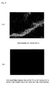
FIG. 2(a) shows a TEM image of a reforming catalyst A manufactured in the example of the present invention, andFIG. 2(b) is a view showing an EDX mapping image related to Ni of the reforming catalyst A. -
FIG. 3(a) shows a TEM image of a reforming catalyst D (comparative example) manufactured for comparison in the example of the present invention, andFIG. 3(b) is a view showing an EDX mapping image related to Ni of the reforming catalyst D. -
FIG. 4(a) shows a TEM image of a reforming catalyst F (comparative example) manufactured for comparison in the example of the present invention, andFIG. 4(b) is a view showing an EDX mapping image related to Ni of the reforming catalyst F. - Hereafter, the features of the present invention will be described in further detail with reference to examples of the present invention.
- Strontium carbonate (SrCO3) and titanium oxide (TiO2) were weighed so as to attain a molar ratio of 2.0 : 1.0, and further, nickel oxide (NiO) was added and mixed so as to attain a ratio of 8.9 parts by mol relative to 100 parts by mol of the Sr2TiO4 to be produced. Subsequently, a binder was added to this mixture for granulation, so as to obtain a spherical granulated body having a diameter of 2 to 5 mm.
Thereafter, the obtained granulated body was placed in air and fired under a condition of 1100°C for one hour to obtain a catalyst A. - As a result of performing an X-ray diffraction measurement on the obtained catalyst A, the obtained diffraction lines were only the diffraction line of the Sr2TiO4 structure. Therefore, it was confirmed that the obtained catalyst A is a NiO-Sr2TiO4 solid solution in which an Ni component is dissolved in the crystal structure of Sr2TiO4, and that the amount of the dissolved Ni component is 8.9 parts by mol relative to 100 parts by mol of Sr2TiO4.
- As will be shown later, this NiO-Sr2TiO4 solid solution will be a mixture of SrTiO3, SrCO3, and Ni and/or NiO after a reforming test. This mixture can be used as a catalyst as well.
- Strontium carbonate (SrCO3) and titanium oxide (TiO2) were weighed so as to attain a molar ratio of 2.0 : 1.0, and further, nickel oxide (NiO) was added and mixed so as to attain a ratio of 13.5 parts by mol relative to 100 parts by mol of the Sr2TiO4 to be produced. Subsequently, a binder was added to this mixture for granulation, so as to obtain a spherical granulated body having a diameter of 2 to 5 mm.
- Thereafter, the obtained granulated body was placed in air and fired under a condition of 1100°C for one hour to obtain a catalyst B.
As a result of performing an X-ray diffraction measurement on the obtained catalyst B, the obtained diffraction lines were only the diffraction line of the Sr2TiO4 structure. Therefore, it was confirmed that the obtained catalyst B is a NiO-Sr2TiO4 solid solution in which an Ni component is dissolved in the crystal structure of Sr2TiO4, and that the amount of the dissolved Ni component is 13.5 parts by mol relative to Sr2TiO4. - Carbon dioxide is allowed to act on this NiO-Sr2TiO4 solid solution to produce SrTiO3, SrCO3, and Ni and/or NiO. This mixture can be used as a catalyst as well.
- Strontium carbonate (SrCO3) and titanium oxide (TiO2) were weighed so as to attain a molar ratio of 2.0 : 1.0, and further, nickel oxide (NiO) was added and mixed so as to attain a ratio of 2.2 parts by mol relative to 100 parts by mol of the Sr2TiO4 to be produced. Subsequently, a binder was added to this mixture for granulation, so as to obtain a spherical granulated body having a diameter of 2 to 5 mm.
- Thereafter, the obtained granulated body was placed in air and fired under a condition of 1100°C for one hour to obtain a catalyst C.
- As a result of performing an X-ray diffraction measurement on the obtained catalyst C, the obtained diffraction lines were only the diffraction line of the Sr2TiO4 structure. Therefore, it was confirmed that the obtained catalyst C is a NiO-Sr2TiO4 solid solution in which an Ni component is dissolved in the crystal structure of Sr2TiO4, and that the amount of the dissolved Ni component is 2.2 parts by mol relative to 100 parts by mol of Sr2TiO4.
- A mixture of SrTiO3, SrCO3, and Ni and/or NiO obtained by allowing carbon dioxide to act on the NiO-Sr2TiO4 solid solution can be used as a catalyst as well.
- Strontium carbonate (SrCO3) and titanium oxide (TiO2) were weighed so as to attain a molar ratio of 2.0 : 1.0, and further, nickel oxide (NiO) was added and mixed so as to attain a ratio of 22.2 parts by mol relative to 100 parts by mol of the Sr2TiO4 to be produced. Subsequently, a binder was added to this mixture for granulation, so as to obtain a spherical granulated body having a diameter of 2 to 5 mm.
- Thereafter, the obtained granulated body was placed in air and fired under a condition of 1100°C for one hour to obtain a reforming catalyst D for comparison.
- As a result of performing an X-ray diffraction measurement on the obtained catalyst D, a diffraction line of NiO phase was confirmed in addition to the diffraction line of the Sr2TiO4 structure. From this result, it was found out that, in the case of the manufactured catalyst D for comparison, the NiO phase exceeding the solid solution limit remains in addition to the NiO-Sr2TiO4 solid solution.
- Strontium carbonate (SrCO3) and titanium oxide (TiO2) were weighed so as to attain a molar ratio of 2.0 : 1.0, and further, nickel oxide (NiO) was added and mixed in the same amount as in the case of the catalyst A. Subsequently, a binder was added to this mixture for granulation, so as to obtain a spherical granulated body having a diameter of 2 to 5 mm.
- Thereafter, the obtained granulated body was placed in air and fired under a condition of 800°C for one hour to obtain a reforming catalyst E for comparison.
- An X-ray diffraction measurement was carried out on the obtained catalyst E. As a result, the diffraction line of the Sr2TiO4 structure was not confirmed, and it was confirmed that the obtained fired body is a mixed body of NiO phase, SrCO3 phase, and SrTiO3 phase. This is due to the fact that the firing temperature was low, and Sr2TiO4 phase was not produced.
- Barium carbonate (BaCO3) and titanium oxide (TiO2) were weighed so as to attain a molar ratio of 2.0 : 1.0, and further, nickel oxide (NiO) was added and mixed so as to attain a ratio of 8.4 parts by mol relative to 100 parts by mol of the Ba2TiO4 to be produced. Subsequently, a binder was added to this mixture for granulation, so as to obtain a spherical granulated body having a diameter of 2 to 5 mm.
- Thereafter, the obtained granulated body was placed in air and fired under a condition of 1100°C for one hour to obtain a reforming catalyst F for comparison.
- An X-ray diffraction measurement was carried out on the obtained catalyst F. As a result, it was confirmed that the obtained fired body is a mixed body of NiO phase and Ba2TiO4 phase, namely, that a solid solution of NiO phase and Ba2TiO4 phase is not formed.
- Strontium carbonate (SrCO3) and zirconium oxide (ZrO2) were weighed so as to attain a molar ratio of 2.0 : 1.0, and further, nickel oxide (NiO) was added and mixed so as to attain a ratio of 8.9 parts by mol relative to 100 parts by mol of the Sr2ZrO4 to be produced. Subsequently, a binder was added to this mixture for granulation, so as to obtain a spherical granulated body having a diameter of 2 to 5 mm.
- Thereafter, the obtained granulated body was placed in air and fired under a condition of 1100°C for one hour to obtain a reforming catalyst G for comparison.
- An X-ray diffraction measurement was carried out on the obtained catalyst G. As a result, it was confirmed that the obtained fired body is a mixed body of NiO phase and Sr2ZrO4 phase, namely, that a solid solution of NiO phase and Sr2ZrO4 phase is not formed.
- Thereafter, with respect to the reforming catalysts A to C provided with the requirements of the present invention and the reforming catalysts D to G for comparison that were fabricated as described above, properties as a reforming catalyst were examined and evaluated by the methods described below.
- As shown in
FIG. 1 , areaction tube 1 made of metal and equipped with aheater 2 in the outside was loaded with 5cc of a reformingcatalyst 3 manufactured in the above-described manner, and a mixed gas of nitrogen and carbon dioxide (ratio of carbon dioxide: 20 vol%) was allowed to flow at a predetermined rate through aninlet 4 of thereaction tube 1. The mixed gas inlet temperature was controlled to be 800°C by theheater 2. After the temperature of the mixed gas to be flowed was stabilized, a mixed gas of methane and carbon dioxide (CH4 : CO2 = 1 : 1 (volume ratio)) was allowed to flow as a source material gas at a flow rate of 10 NL/h instead of the above mixed gas, so as to perform a reforming test for 8 hours. - Here, during the reforming test, the pressure within the
reaction tube 1 was adjusted to 9 atm in terms of absolute pressure by adjusting a back-pressure valve 6 disposed on anoutlet 5 side of thereaction tube 1.
Also, during the test, the gas obtained through theoutlet 5 was introduced into an analyzing apparatus to measure a gas concentration. - Further, after the test was finished, the gas flow was stopped to perform cooling, and the reforming
catalyst 3 was taken out from thereaction tube 1 to perform thermal weight measurement under CO2 flow. Here, in the thermal weight measurement, the carbon deposited on the sample and CO2 were allowed to react as in the following formula (2):
C + CO2 ⇒ 2CO (2)
so as to estimate a decrease in the sample weight as a carbon deposition amount. - Further, with respect to the reforming
catalyst 3 after the test was finished, an X-ray diffraction measurement was carried out to identify the crystal phase. - Table 1 shows a methane conversion ratio by the following formula (3):
CH4 + CO2 ⇒ 2H2 + 2CO (3)
through the reforming reaction. The methane conversion ratio is a value showing how much part of the introduced methane was converted into other substances (mainly carbon monoxide and hydrogen) by the reforming reaction, and the methane conversion ratio of Table 1 is a value showing a ratio of methane converted into other substances in percentage relative to the introduced methane.
Further, Table 1 shows a carbon deposition amount and a crystal phase identified by the X-ray diffraction measurement with respect to the catalysts after the test. -
[TABLE 1] Catalyst Methane conversion ratio [%] Deposited Carbon [wt %] Crystal phase after test SrCO3 A 58 0 SrTiO3 Ni and/or NiO SrCO3 B 58 0 SrTiO3 Ni and/or NiO SrCO3 C 42 0 SrTiO3 Ni and/or NiO SrCO3 D 58 0.5 SrTiO3 Ni and/or NiO SrCO3 E 57 2.8 SrTiO3 Ni and/or NiO BaCO3 F 55 > 10 BaTiO3 Ni and/or NiO SrCO3 G 57 0.6 SrZrO3 Ni and/or NiO - As shown in Table 1, the reforming catalysts A, B, and D to G showed a methane conversion ratio close to the equilibrium gas composition under a condition of 800°C and 9 atm; however, the catalysts D to G generated carbon deposition. Here, the catalyst C did not generate carbon deposition though the catalyst C did not reach the equilibrium gas composition.
- Also, from the crystal phase after the test, it was understood that all of the catalysts A to E having passed the test are constituted with SrCO3, SrTiO3, and Ni and/or NiO. However, the catalysts D and E in which the source material NiO remained in the manufacturing process generated carbon deposition while the catalysts A to C in which the total amount of the source material NiO was converted into a solid solution of NiO-Sr2TiO4 in the manufacturing process did not generate carbon deposition.
- Similarly, in the cases of the catalyst F in which Sr in the catalyst A was replaced with Ba and the catalyst G in which Ti in the catalyst A was replaced with Zr, the source material NiO remained in the manufacturing process, so that, when these catalysts F and G were used, carbon deposition was generated.
- Here, the TEM images of the reforming catalysts A, D, and F after the test are shown in
FIG. 2(a) ,FIG. 3(a) , andFIG. 4(a) , respectively, and the mapping images of Ni by the energy dispersion type X-ray spectroscopy (EDX) of the reforming catalysts A, D, and F are shown inFIG. 2(b) ,FIG. 3(b) , andFIG. 4(b) , respectively. - In the reforming catalyst A, Ni grains having a grain size of 50 nm or less can be confirmed as shown in
FIGS. 2(a) and 2(b) . In contrast, the reforming catalyst F in which the source material NiO did not form a NiO-Ba2TiO4 solid solution in the manufacturing process is constituted with Ni grains having a grain size of 100 nm or more as shown inFIGS. 4(a) and 4(b) , and is found to keep the grain size equivalent to that of the grains of the source material NiO. - Also, it is understood that, in the reforming catalyst D in which NiO exceeding the solid solution limit is added, large Ni grains having a grain size exceeding 100 nm remain as shown in
FIGS. 3(a) and 3(b) because a part of NiO remains without being dissolved. - In the reforming catalysts A to C according to the examples of the present invention that have been produced via the process in which a NiO-Sr2TiO4 solid solution is formed, the Ni component is brought into a state of being fully dissolved and dispersed in the whole of the solid solution when the solid solution is formed. Therefore, it is possible to obtain metal Ni and/or NiO grains having a small grain size of 50 nm or less when the Ni phase and/or the NiO phase is deposited. It is supposed that, by the effect of this miniaturization of Ni and/or NiO, the function of restraining carbon deposition is enhanced.
- On the other hand, in the reforming catalyst D of the comparative example, an excessive amount of NiO exceeding the solid solution limit is added, so that Ni and/or NiO grains having a large grain size equivalent to that of the source material NiO remain in the manufactured catalyst D. As a result, it is supposed that carbon deposition is liable to be generated under a high-pressure condition.
Here, from the result of the reforming catalysts A, B, C, and D, the amount of the dissolved Ni component is preferably within a range of 2.2 parts by mol to 13.5 parts by mol relative to 100 parts by mol of Sr2TiO4. - Also, though the reforming catalyst E has the same composition as the reforming catalyst A in terms of the preparation composition of the source materials, the reforming catalyst E has a low firing temperature of 800°C in the manufacturing step, so that the NiO-Sr2TiO4 solid solution is not formed in the manufacturing process. For this reason, Ni and/or NiO grains having a large grain size equivalent to that of the source material NiO remains and, as a result, it is supposed that carbon deposition is liable to be generated under a high-pressure condition.
- Also, in the reforming catalysts F and G, a NiO-Ba2TiO4 solid solution or a NiO-Sr2ZrO4 solid solution is not formed in the manufacturing process, so that Ni and/or NiO having a large grain size remains in the catalysts, and it is supposed that carbon deposition is liable to be generated.
- In the above-described examples, a NiO-Sr2TiO4 solid solution was formed by thermally treating a mixture of NiO, SrCO3, and TiO2; however, the reforming catalyst of the present invention containing SrTiO3, SrCO3, and Ni and/or NiO can be manufactured by forming a NiO-Sr2TiO4 solid solution by thermally treating a mixture containing Ni and/or NiO, SrCO3, and SrTiO3 at a temperature of 900°C or higher.
- As shown in
FIG. 1 , areaction tube 1 made of metal and equipped with aheater 2 in the outside was loaded with 5cc of the reforming catalyst A manufactured in the above-described manner, and a mixed gas of nitrogen and carbon dioxide (ratio of carbon dioxide: 20 vol%) was allowed to flow through aninlet 4 of thereaction tube 1. The mixed gas inlet temperature was controlled to be 900°C by theheater 2. - Thereafter, various source material mixed gases shown in Table 2 were allowed to flow at a flow rate of 10 NL/h for 8 hours, so as to start and carry out a reforming test of 8 hours.
During the reforming test, the pressure within thereaction tube 1 was adjusted to 5 atm in terms of absolute pressure by adjusting a back-pressure valve 6 disposed on anoutlet 5 side of thereaction tube 1.
Also, during the test, the gas obtained through theoutlet 5 was introduced into an analyzing apparatus to measure a gas concentration. - Further, after the test was finished, the gas flow was stopped to perform cooling, and the reforming
catalyst 3 was taken out from thereaction tube 1 to perform thermal weight measurement under CO2 flow. Here, in the thermal weight measurement, the carbon deposited on the sample and CO2 were allowed to react as in the following formula (2):
C + CO2 ⇒ 2CO (2)
so as to estimate a decrease in the sample weight as a carbon deposition amount. - Table 2 shows source material gas composition, reaction conversion ratio of methane to carbon monoxide, and carbon deposition amount.
Here, thetest number 1 of Table 2 represents reforming with carbon dioxide in which methane, which is hydrocarbon, and carbon dioxide are allowed to react with each other; thetest numbers test number 4 represents reforming with water vapor in which methane, which is hydrocarbon, and water vapor are allowed to react with each other. -
[TABLE 2] Test number Source material gas composition
(CH4 : CO2 : H2O)Methane conversion ratio
[%]Deposited carbon
[wt%]1 1 : 1 : 0
(reforming with carbon dioxide)86 0 2 1 : 0.5 : 0.5
(combination reforming)85 0 3 1 : 0.25 : 0.75
(combination reforming)85 0 4 1 : 0 : 1
(reforming with water vapor)85 0 - As is shown in Table 2, under any of the source material gas conditions (namely, in any of the reforming reactions of reforming with carbon dioxide, combination reforming, and reforming with water vapor), the reforming reaction proceeds sufficiently when the catalyst A is used, and the catalyst A was confirmed to exhibit a methane conversion ratio close to the equilibrium gas composition at 900°C / 5 atm.
- Also, it was confirmed that carbon deposition is not generated even by combination reforming in which both of carbon dioxide and water vapor are allowed to react on methane in the
test numbers
Further, it was confirmed that carbon deposition is not generated even by reforming reaction of methane with water vapor in the ratio of CH4 / H2O = 1. - The inside of a
reaction tube 1 of an apparatus shown inFIG. 1 was loaded with 5cc of the above catalyst A, and a mixed gas of nitrogen and carbon dioxide (ratio of carbon dioxide: 20 vol%) was allowed to flow at a predetermined rate through aninlet 4 of thereaction tube 1. The mixed gas inlet temperature was controlled to be 900°C by aheater 2.
Thereafter, various source material mixed gases shown by the test number 11 or 13 of Table 3 were allowed to flow at a flow rate of 10 NL/h, so as to carry out a reforming test of 100 hours. Here, during the reforming test, a back-pressure valve was opened to attain 1 atm.
For comparison, the inside of areaction tube 1 of an apparatus shown inFIG. 1 was loaded with 5cc of a commercially available reforming catalyst H containing NiO and alumina as major components, and a nitrogen gas was allowed to flow through aninlet 4 of thereaction tube 1. The mixed gas inlet temperature was controlled to be 900°C by aheater 2.
Thereafter, various source material mixed gases shown by the test number 12 or 14 of Table 3 were allowed to flow at a flow rate of 10 NL/h, so as to carry out a reforming test of 100 hours. Here, during the reforming test, a back-pressure valve was opened to attain 1 atm.
Table 3 shows source material gas composition, reaction conversion ratio of methane to carbon monoxide, and carbon deposition amount. -
[TABLE 3] Test number Source material gas composition
(CH4 : CO2 : H2O)Catalyst Methane conversion ratio
[%]Deposited carbon
[wt %]11 1 : 1 : 0
(reforming with carbon dioxide)A 96 0 12 1 : 1 : 0
(reforming with carbon dioxide)H 96 > 10 13 1 : 0 : 1
(reforming with water vapor)A 96 0 14 1 : 0 : 1
(reforming with water vapor)H 96 2.1 - As shown in Table 3, in the reforming test of the test number 12 carried out under a condition of CH4 : CO2 = 1 : 1 by using the commercially available reforming catalyst H, the reaction tube was clogged and the internal pressure rose after several hours from the start of the test, so that the test was stopped. Carbon was mingled in the catalyst that had been taken out, and 10g or more of carbon was collected.
- Also, in the reforming test of the test number 14 carried out under a condition of CH4 : H2O = 1 : 1 by using the commercially available reforming catalyst H, there was no rise in the internal pressure of the reaction tube, and a reforming test of 100 hours could be carried out. The catalyst taken out was fired in an oxygen atmosphere, and the burnt carbon amount was estimated by measuring the concentration of CO2 contained in the outlet gas. Though the carbon deposition amount in the reforming test with water vapor was a smaller amount as compared with the time of reforming with carbon dioxide; however, a carbon deposition of 2.1 wt% was generated, so that it was confirmed that the accumulation of carbon raises a problem under a practical operation condition exceeding several thousand hours.
- In contrast, with respect to the catalyst A, there was no rise in the internal pressure of the reaction tube in any of the condition of CH4 : CO2 = 1 : 1 of the test number 11 and the condition of CH4 : H2O = 1 : 1 of the test number 13, so that a reforming test of 100 hours could be carried out. Also, carbon deposition was not confirmed from the thermal weight measurement under CO2 flow.
- From the above results, it was confirmed that the catalyst A is excellent in the capability of restraining and preventing carbon deposition as compared with the commercially available reforming catalyst H. Also, it was confirmed that the effect thereof is not limited to the reforming reaction of methane with carbon dioxide but has a conspicuous effect even in the reforming reaction of methane with water vapor.
- The present invention is not limited to the above-described examples further in other respects, so that various applications and modifications can be added within the range of the invention with respect to the condition in the step of producing a NiO-Sr2TiO4 solid solution, the condition in the step of producing SrTiO3, SrCO3, and Ni and/or NiO by allowing carbon dioxide to act on the NiO-Sr2TiO4 solid solution, the specific conditions of the reforming reaction, and the like.
- As described above, the present invention makes it possible to manufacture efficiently a reforming catalyst capable of efficiently manufacturing a synthesized gas containing hydrogen and carbon monoxide from a hydrocarbon source material gas while restraining carbon deposition when the catalyst is used in any of the reforming reactions of reforming with carbon dioxide in which reforming is carried out by allowing hydrocarbon and carbon dioxide to react with each other, reforming with water vapor in which reforming is carried out by allowing hydrocarbon and water vapor to react with each other, and combination reforming with use of both of carbon dioxide and water vapor.
Therefore, the present invention can be widely applied to the field of reforming catalysts and the field of art related to the manufacture of a synthesized gas containing hydrogen and carbon monoxide. -
- 1
- reaction tube
- 2
- heater
- 3
- reforming catalyst
- 4
- inlet of reaction tube
- 5
- outlet of reaction tube
- 6
- back-pressure valve
Claims (8)
- A hydrocarbon gas reforming catalyst used for producing a synthesized gas containing carbon monoxide and hydrogen by reforming a hydrocarbon gas with use of carbon dioxide and/or water vapor, comprising a NiO-Sr2TiO4 solid solution in which NiO is dissolved in Sr2TiO4.
- The hydrocarbon gas reforming catalyst according to claim 1, wherein the ratio of NiO in the NiO-Sr2TiO4 solid solution is a ratio of 2.2 to 13.5 parts by mol relative to 100 parts by mol of Sr2TiO4.
- A hydrocarbon gas reforming catalyst used for producing a synthesized gas containing carbon monoxide and hydrogen by reforming a hydrocarbon gas with use of carbon dioxide and/or water vapor, comprising SrTiO3, SrCO3 and Ni and/or NiO that are produced by allowing carbon dioxide to act on the NiO-Sr2TiO4 solid solution according to claim 1 or 2.
- A method of manufacturing a hydrocarbon gas reforming catalyst, the catalyst being used for producing a synthesized gas containing carbon monoxide and hydrogen by reforming a hydrocarbon source material gas with use of carbon dioxide and/or water vapor and containing a NiO-Sr2TiO4 solid solution in which NiO is dissolved in Sr2TiO4 as a major component, comprising a step of:producing the NiO-Sr2TiO4 solid solution in which NiO is dissolved in Sr2TiO4 by thermally treating a mixture containing SrTiO3, SrCO3, and Ni and/or NiO at a temperature of 900°C or higher.
- A method of manufacturing a hydrocarbon gas reforming catalyst, the catalyst being used for producing a synthesized gas containing carbon monoxide and hydrogen by reforming a hydrocarbon source material gas with use of carbon dioxide and/or water vapor and containing a NiO-Sr2TiO4 solid solution in which NiO is dissolved in Sr2TiO4 as a major component, comprising a step of:producing the NiO-Sr2TiO4 solid solution in which NiO is dissolved in Sr2TiO4 by thermally treating a mixture containing TiO2, SrCO3, and Ni and/or NiO at a temperature of 900°C or higher.
- A method of manufacturing a hydrocarbon gas reforming catalyst, the catalyst being used for producing a synthesized gas containing carbon monoxide and hydrogen by reforming a hydrocarbon source material gas with use of carbon dioxide and/or water vapor and containing SrTiO3, SrCO3, and Ni and/or NiO as major components, comprising steps of:producing a NiO-Sr2TiO4 solid solution in which NiO is dissolved in Sr2TiO4 by thermally treating a mixture containing SrTiO3, SrCO3 and Ni and/or NiO at a temperature of 900°C or higher; andproducing SrTiO3, SrCO3, and Ni and/or NiO by allowing carbon dioxide to act on the NiO-Sr2TiO4 solid solution.
- A method of manufacturing a hydrocarbon gas reforming catalyst, the catalyst being used for producing a synthesized gas containing carbon monoxide and hydrogen by reforming a hydrocarbon source material gas with use of carbon dioxide and/or water vapor and containing SrTiO3, SrCO3 and Ni and/or NiO as major components, comprising steps of:producing a NiO-Sr2TiO4 solid solution in which NiO is dissolved in Sr2TiO4 by thermally treating a mixture containing TiO2, SrCO3, and Ni and/or NiO at a temperature of 900°C or higher; andproducing SrTiO3, SrCO3, and Ni and/or NiO by allowing carbon dioxide to act on the NiO-Sr2TiO4 solid solution.
- A method of manufacturing a synthesized gas, comprising steps of:producing a NiO-Sr2TiO4 solid solution in which NiO is dissolved in Sr2TiO4;producing SrTiO3, SrCO3, and Ni and/or NiO by allowing carbon dioxide to act on the NiO-Sr2TiO4 solid solution; andproducing the synthesized gas containing carbon monoxide and hydrogen by allowing a gas containing a hydrocarbon source material gas and carbon dioxide and/or water vapor to flow through a reformer filled with the catalyst containing SrTiO3, SrCO3, and Ni and/or NiO as major components, so as to bring the gas into contact with the reforming catalyst.
Applications Claiming Priority (3)
| Application Number | Priority Date | Filing Date | Title |
|---|---|---|---|
| JP2009141085 | 2009-06-12 | ||
| JP2009191712 | 2009-08-21 | ||
| PCT/JP2010/059817 WO2010143676A1 (en) | 2009-06-12 | 2010-06-10 | Hydrocarbon gas reforming catalyst, method for producing same, and method for producing synthetic gas |
Publications (3)
| Publication Number | Publication Date |
|---|---|
| EP2441517A1 true EP2441517A1 (en) | 2012-04-18 |
| EP2441517A4 EP2441517A4 (en) | 2014-03-12 |
| EP2441517B1 EP2441517B1 (en) | 2022-04-13 |
Family
ID=43308931
Family Applications (1)
| Application Number | Title | Priority Date | Filing Date |
|---|---|---|---|
| EP10786207.0A Active EP2441517B1 (en) | 2009-06-12 | 2010-06-10 | Hydrocarbon gas reforming catalyst, method for producing same, and method for producing synthetic gas |
Country Status (5)
| Country | Link |
|---|---|
| US (1) | US8329612B2 (en) |
| EP (1) | EP2441517B1 (en) |
| JP (1) | JP5327323B2 (en) |
| CN (1) | CN102802789B (en) |
| WO (1) | WO2010143676A1 (en) |
Cited By (3)
| Publication number | Priority date | Publication date | Assignee | Title |
|---|---|---|---|---|
| EP2505261A4 (en) * | 2009-11-27 | 2013-05-15 | Murata Manufacturing Co | CATALYTIC ANTI-CONVERSION REACTION CATALYST, AND PROCESS FOR PRODUCTION OF SYNTHETIC GAS USING THE CATALYST |
| EP2474355A4 (en) * | 2009-09-02 | 2014-11-05 | Murata Manufacturing Co | HYDROCARBON GAS REFORMING CATALYST, PROCESS FOR PRODUCING THE SAME, AND PROCESS FOR PRODUCING SYNTHESIS GAS |
| WO2014184685A3 (en) * | 2013-05-09 | 2015-02-26 | Sabic Global Technologies B.V. | Alkaline earth metal/metal oxide supported catalysts |
Families Citing this family (9)
| Publication number | Priority date | Publication date | Assignee | Title |
|---|---|---|---|---|
| CN102076604B (en) * | 2008-07-04 | 2014-11-12 | 株式会社村田制作所 | Carbon dioxide reforming process |
| WO2013187436A1 (en) * | 2012-06-13 | 2013-12-19 | 株式会社村田製作所 | Reforming catalyst, method for preparing same, and process for manufacturing synthesis gas |
| KR101363384B1 (en) | 2012-09-28 | 2014-02-14 | 한국과학기술연구원 | Perovskite-supported catalysts for combined steam and carbon dioxide reforming with natural gas |
| WO2014189006A1 (en) * | 2013-05-21 | 2014-11-27 | 株式会社村田製作所 | Catalyst for reforming hydrocarbon-based gas and method for reforming hydrocarbon-based gas using same |
| JP6765240B2 (en) * | 2016-07-12 | 2020-10-07 | 東京瓦斯株式会社 | Fuel cell system |
| EP3603799A4 (en) * | 2018-05-11 | 2020-12-23 | Murata Manufacturing Co., Ltd. | Catalyst for the decomposition of organic materials, aggregate for the decomposition of organic materials and device for the decomposition of organic materials |
| BR112022021340A2 (en) * | 2020-05-04 | 2023-04-11 | Infinium Technology Llc | PROCESS OF CAPTURING CARBON DIOXIDE FROM THE AIR AND THE DIRECT CONVERSION OF CARBON DIOXIDE INTO FUELS AND CHEMICALS |
| KR102768685B1 (en) | 2022-03-22 | 2025-02-18 | 한국과학기술연구원 | Manufacturing method of syngas using carbon swing adsorption |
| CN120861056B (en) * | 2025-07-29 | 2026-03-06 | 四川氢碳氧科技有限公司 | A method for preparing Ni/TiO2 nanorod catalysts and their applications |
Family Cites Families (13)
| Publication number | Priority date | Publication date | Assignee | Title |
|---|---|---|---|---|
| GB8514209D0 (en) * | 1985-06-05 | 1985-07-10 | Unilever Plc | Catalyst additives |
| JPH08231204A (en) | 1994-12-27 | 1996-09-10 | Sekiyu Sangyo Kasseika Center | Method for producing hydrogen and carbon monoxide by carbon dioxide reforming reaction |
| JP3638358B2 (en) | 1995-12-20 | 2005-04-13 | 財団法人石油産業活性化センター | Carbon dioxide reforming catalyst and reforming method using the same |
| JP3086867B2 (en) * | 1997-01-09 | 2000-09-11 | 工業技術院長 | Catalyst for syngas production and method for syngas production |
| US6130182A (en) * | 1997-07-25 | 2000-10-10 | International Business Machines Corporation | Dielectric catalyst structures |
| JP3525184B2 (en) * | 2000-08-23 | 2004-05-10 | 独立行政法人産業技術総合研究所 | Catalyst for producing hydrogen and method for producing hydrogen |
| US20040018409A1 (en) * | 2002-02-28 | 2004-01-29 | Shiqiang Hui | Solid oxide fuel cell components and method of manufacture thereof |
| JP4202072B2 (en) * | 2002-08-30 | 2008-12-24 | 三菱重工業株式会社 | Method for preparing hydrogen production catalyst |
| CN100490965C (en) * | 2004-08-03 | 2009-05-27 | 株式会社村田制作所 | Carbon dioxide absorbing material, carbon dioxide separation method using same, and carbon dioxide separation device |
| JP2006346598A (en) * | 2005-06-16 | 2006-12-28 | Nissan Motor Co Ltd | Steam reforming catalyst |
| WO2006137211A1 (en) * | 2005-06-24 | 2006-12-28 | Murata Manufacturing Co., Ltd. | Reforming apparatus for fuel cell |
| JP2009509751A (en) * | 2005-09-29 | 2009-03-12 | トラスティーズ オブ ボストン ユニバーシティ | Mixed ion and electron conducting membranes |
| JP4420127B2 (en) * | 2007-01-09 | 2010-02-24 | 株式会社村田製作所 | Carbon dioxide reforming catalyst and method for producing the same |
-
2010
- 2010-06-10 EP EP10786207.0A patent/EP2441517B1/en active Active
- 2010-06-10 CN CN201080026390.XA patent/CN102802789B/en active Active
- 2010-06-10 JP JP2011518570A patent/JP5327323B2/en active Active
- 2010-06-10 WO PCT/JP2010/059817 patent/WO2010143676A1/en not_active Ceased
-
2011
- 2011-12-06 US US13/311,646 patent/US8329612B2/en active Active
Non-Patent Citations (7)
| Title |
|---|
| ANDREW M. BEALE ET AL: "Combined experimental and computational modelling studies of the solubility of nickel in strontium titanate", JOURNAL OF MATERIALS CHEMISTRY, vol. 19, no. 25, 1 January 2009 (2009-01-01), page 4391, XP055098684, ISSN: 0959-9428, DOI: 10.1039/b902591j * |
| KAZUNARI DOMEN ET AL: "Photocatalytic decomposition of water into hydrogen and oxygen over nickel(II) oxide-strontium titanate (SrTiO3) powder. 1. Structure of the catalysts", THE JOURNAL OF PHYSICAL CHEMISTRY, vol. 90, no. 2, 1 January 1986 (1986-01-01), pages 292-295, XP055098672, ISSN: 0022-3654, DOI: 10.1021/j100274a018 * |
| KAZUNARI DOMEN ET AL: "Study of the photocatalytic decomposition of water vapor over a nickel(II) oxide-strontium titanate (SrTiO3) catalyst", THE JOURNAL OF PHYSICAL CHEMISTRY, vol. 86, no. 18, 1 September 1982 (1982-09-01), pages 3657-3661, XP055098669, ISSN: 0022-3654, DOI: 10.1021/j100215a032 * |
| KOHEI URASAKI ET AL: "Hydrogen Production by Steam Reforming of Ethanol Using Cobalt and Nickel Catalysts Supported on Strontium Titanate", CHEMISTRY LETTERS, vol. 34, no. 5, 1 January 2005 (2005-01-01), pages 668-669, XP055098681, ISSN: 0366-7022, DOI: 10.1246/cl.2005.668 * |
| See also references of WO2010143676A1 * |
| Takashi Hayakawa ET AL: "Sustainable Ni/Cal_xSrxTiO 3 catalyst prepared in situ for the partial oxidation of methane to synthesis gas", ELSEVIER Applied Catalysis A: General, 1 January 1997 (1997-01-01), pages 391-410, XP055098680, Retrieved from the Internet: URL:http://ac.els-cdn.com/S0926860X96002748/1-s2.0-S0926860X96002748-main.pdf?_tid=fa4078c6-8769-11e3-b3d7-00000aab0f6b&acdnat=1390837679_d8479f7098f303b80053ffab3314c903 [retrieved on 2014-01-27] * |
| TAKEHIRA K ET AL: "PARTIAL OXIDATION OF METHANE TO SYNTHESIS GAS OVER (CA,SR) (TI,NI) OXIDES", CATALYSIS TODAY, AMSTERDAM, NL, vol. 24, no. 3, 23 May 1995 (1995-05-23), pages 237-242,I/II, XP002907446, DOI: 10.1016/0920-5861(95)00031-A * |
Cited By (6)
| Publication number | Priority date | Publication date | Assignee | Title |
|---|---|---|---|---|
| EP2474355A4 (en) * | 2009-09-02 | 2014-11-05 | Murata Manufacturing Co | HYDROCARBON GAS REFORMING CATALYST, PROCESS FOR PRODUCING THE SAME, AND PROCESS FOR PRODUCING SYNTHESIS GAS |
| EP2505261A4 (en) * | 2009-11-27 | 2013-05-15 | Murata Manufacturing Co | CATALYTIC ANTI-CONVERSION REACTION CATALYST, AND PROCESS FOR PRODUCTION OF SYNTHETIC GAS USING THE CATALYST |
| US8540898B2 (en) | 2009-11-27 | 2013-09-24 | Murata Manufacturing Co., Ltd. | Catalyst for reverse shift reaction and method for producing synthesis gas using the same |
| WO2014184685A3 (en) * | 2013-05-09 | 2015-02-26 | Sabic Global Technologies B.V. | Alkaline earth metal/metal oxide supported catalysts |
| EP2994226A2 (en) * | 2013-05-09 | 2016-03-16 | SABIC Global Technologies B.V. | Alkaline earth metal/metal oxide supported catalysts |
| US9616414B2 (en) | 2013-05-09 | 2017-04-11 | Sabic Global Technologies B.V. | Alkaline earth metal/metal oxide supported catalysts |
Also Published As
| Publication number | Publication date |
|---|---|
| US20120074357A1 (en) | 2012-03-29 |
| CN102802789B (en) | 2014-10-15 |
| JP5327323B2 (en) | 2013-10-30 |
| JPWO2010143676A1 (en) | 2012-11-29 |
| EP2441517B1 (en) | 2022-04-13 |
| US8329612B2 (en) | 2012-12-11 |
| WO2010143676A1 (en) | 2010-12-16 |
| CN102802789A (en) | 2012-11-28 |
| EP2441517A4 (en) | 2014-03-12 |
Similar Documents
| Publication | Publication Date | Title |
|---|---|---|
| US8329612B2 (en) | Catalyst for reforming hydrocarbon gas, method of manufacturing the same, and method of manufacturing synthesized gas | |
| US7923409B2 (en) | Catalyst for hydrogen generation through steam reforming of hydrocarbons | |
| EP2033943B1 (en) | Catalyst for methanation of carbon oxides, preparation method of the catalyst and process for the methanation | |
| JP5141765B2 (en) | Carbon dioxide reforming method | |
| JP5126560B2 (en) | Hydrocarbon gas reforming catalyst, method for producing the same, and method for producing synthesis gas | |
| JP5402683B2 (en) | Reverse shift reaction catalyst, method for producing the same, and method for producing synthesis gas | |
| US20140332726A1 (en) | Alkaline earth metal/metal oxide supported catalysts | |
| EP3804850B1 (en) | Hydrocarbon reforming catalyst and hydrocarbon reforming apparatus | |
| US20180043340A1 (en) | Use of nickel-manganese olivine and nickel-manganese spinel as bulk metal catalysts for carbon dioxide reforming of methane | |
| US12390792B2 (en) | Hydrocarbon reforming catalyst and hydrocarbon reforming device | |
| EP4070885A1 (en) | Hydrocarbon reforming catalyst and hydrocarbon reforming device | |
| EP3988206B1 (en) | Hydrocarbon reforming catalyst and hydrocarbon reforming device | |
| JP7347541B2 (en) | Hydrocarbon reforming catalyst, hydrocarbon reformer, and method for recovering sulfur deterioration of hydrocarbon reforming catalyst |
Legal Events
| Date | Code | Title | Description |
|---|---|---|---|
| PUAI | Public reference made under article 153(3) epc to a published international application that has entered the european phase |
Free format text: ORIGINAL CODE: 0009012 |
|
| 17P | Request for examination filed |
Effective date: 20111117 |
|
| AK | Designated contracting states |
Kind code of ref document: A1 Designated state(s): AL AT BE BG CH CY CZ DE DK EE ES FI FR GB GR HR HU IE IS IT LI LT LU LV MC MK MT NL NO PL PT RO SE SI SK SM TR |
|
| DAX | Request for extension of the european patent (deleted) | ||
| A4 | Supplementary search report drawn up and despatched |
Effective date: 20140207 |
|
| RIC1 | Information provided on ipc code assigned before grant |
Ipc: C01B 31/18 20060101ALI20140203BHEP Ipc: B01J 27/232 20060101ALI20140203BHEP Ipc: B01J 23/78 20060101AFI20140203BHEP Ipc: B01J 37/08 20060101ALI20140203BHEP Ipc: C01B 3/40 20060101ALI20140203BHEP |
|
| STAA | Information on the status of an ep patent application or granted ep patent |
Free format text: STATUS: EXAMINATION IS IN PROGRESS |
|
| 17Q | First examination report despatched |
Effective date: 20171207 |
|
| GRAP | Despatch of communication of intention to grant a patent |
Free format text: ORIGINAL CODE: EPIDOSNIGR1 |
|
| STAA | Information on the status of an ep patent application or granted ep patent |
Free format text: STATUS: GRANT OF PATENT IS INTENDED |
|
| RIC1 | Information provided on ipc code assigned before grant |
Ipc: C01B 3/40 20060101ALI20211001BHEP Ipc: B01J 37/08 20060101ALI20211001BHEP Ipc: B01J 27/232 20060101ALI20211001BHEP Ipc: B01J 23/78 20060101AFI20211001BHEP |
|
| INTG | Intention to grant announced |
Effective date: 20211102 |
|
| GRAS | Grant fee paid |
Free format text: ORIGINAL CODE: EPIDOSNIGR3 |
|
| GRAA | (expected) grant |
Free format text: ORIGINAL CODE: 0009210 |
|
| STAA | Information on the status of an ep patent application or granted ep patent |
Free format text: STATUS: THE PATENT HAS BEEN GRANTED |
|
| AK | Designated contracting states |
Kind code of ref document: B1 Designated state(s): AL AT BE BG CH CY CZ DE DK EE ES FI FR GB GR HR HU IE IS IT LI LT LU LV MC MK MT NL NO PL PT RO SE SI SK SM TR |
|
| REG | Reference to a national code |
Ref country code: GB Ref legal event code: FG4D |
|
| REG | Reference to a national code |
Ref country code: CH Ref legal event code: EP |
|
| REG | Reference to a national code |
Ref country code: DE Ref legal event code: R096 Ref document number: 602010068188 Country of ref document: DE |
|
| REG | Reference to a national code |
Ref country code: IE Ref legal event code: FG4D |
|
| REG | Reference to a national code |
Ref country code: AT Ref legal event code: REF Ref document number: 1482968 Country of ref document: AT Kind code of ref document: T Effective date: 20220515 |
|
| REG | Reference to a national code |
Ref country code: LT Ref legal event code: MG9D |
|
| REG | Reference to a national code |
Ref country code: NL Ref legal event code: MP Effective date: 20220413 |
|
| REG | Reference to a national code |
Ref country code: AT Ref legal event code: MK05 Ref document number: 1482968 Country of ref document: AT Kind code of ref document: T Effective date: 20220413 |
|
| PG25 | Lapsed in a contracting state [announced via postgrant information from national office to epo] |
Ref country code: NL Free format text: LAPSE BECAUSE OF FAILURE TO SUBMIT A TRANSLATION OF THE DESCRIPTION OR TO PAY THE FEE WITHIN THE PRESCRIBED TIME-LIMIT Effective date: 20220413 |
|
| PG25 | Lapsed in a contracting state [announced via postgrant information from national office to epo] |
Ref country code: SE Free format text: LAPSE BECAUSE OF FAILURE TO SUBMIT A TRANSLATION OF THE DESCRIPTION OR TO PAY THE FEE WITHIN THE PRESCRIBED TIME-LIMIT Effective date: 20220413 Ref country code: PT Free format text: LAPSE BECAUSE OF FAILURE TO SUBMIT A TRANSLATION OF THE DESCRIPTION OR TO PAY THE FEE WITHIN THE PRESCRIBED TIME-LIMIT Effective date: 20220816 Ref country code: NO Free format text: LAPSE BECAUSE OF FAILURE TO SUBMIT A TRANSLATION OF THE DESCRIPTION OR TO PAY THE FEE WITHIN THE PRESCRIBED TIME-LIMIT Effective date: 20220713 Ref country code: LT Free format text: LAPSE BECAUSE OF FAILURE TO SUBMIT A TRANSLATION OF THE DESCRIPTION OR TO PAY THE FEE WITHIN THE PRESCRIBED TIME-LIMIT Effective date: 20220413 Ref country code: HR Free format text: LAPSE BECAUSE OF FAILURE TO SUBMIT A TRANSLATION OF THE DESCRIPTION OR TO PAY THE FEE WITHIN THE PRESCRIBED TIME-LIMIT Effective date: 20220413 Ref country code: GR Free format text: LAPSE BECAUSE OF FAILURE TO SUBMIT A TRANSLATION OF THE DESCRIPTION OR TO PAY THE FEE WITHIN THE PRESCRIBED TIME-LIMIT Effective date: 20220714 Ref country code: FI Free format text: LAPSE BECAUSE OF FAILURE TO SUBMIT A TRANSLATION OF THE DESCRIPTION OR TO PAY THE FEE WITHIN THE PRESCRIBED TIME-LIMIT Effective date: 20220413 Ref country code: ES Free format text: LAPSE BECAUSE OF FAILURE TO SUBMIT A TRANSLATION OF THE DESCRIPTION OR TO PAY THE FEE WITHIN THE PRESCRIBED TIME-LIMIT Effective date: 20220413 Ref country code: BG Free format text: LAPSE BECAUSE OF FAILURE TO SUBMIT A TRANSLATION OF THE DESCRIPTION OR TO PAY THE FEE WITHIN THE PRESCRIBED TIME-LIMIT Effective date: 20220713 Ref country code: AT Free format text: LAPSE BECAUSE OF FAILURE TO SUBMIT A TRANSLATION OF THE DESCRIPTION OR TO PAY THE FEE WITHIN THE PRESCRIBED TIME-LIMIT Effective date: 20220413 |
|
| PG25 | Lapsed in a contracting state [announced via postgrant information from national office to epo] |
Ref country code: PL Free format text: LAPSE BECAUSE OF FAILURE TO SUBMIT A TRANSLATION OF THE DESCRIPTION OR TO PAY THE FEE WITHIN THE PRESCRIBED TIME-LIMIT Effective date: 20220413 Ref country code: LV Free format text: LAPSE BECAUSE OF FAILURE TO SUBMIT A TRANSLATION OF THE DESCRIPTION OR TO PAY THE FEE WITHIN THE PRESCRIBED TIME-LIMIT Effective date: 20220413 Ref country code: IS Free format text: LAPSE BECAUSE OF FAILURE TO SUBMIT A TRANSLATION OF THE DESCRIPTION OR TO PAY THE FEE WITHIN THE PRESCRIBED TIME-LIMIT Effective date: 20220813 |
|
| REG | Reference to a national code |
Ref country code: DE Ref legal event code: R097 Ref document number: 602010068188 Country of ref document: DE |
|
| PG25 | Lapsed in a contracting state [announced via postgrant information from national office to epo] |
Ref country code: SM Free format text: LAPSE BECAUSE OF FAILURE TO SUBMIT A TRANSLATION OF THE DESCRIPTION OR TO PAY THE FEE WITHIN THE PRESCRIBED TIME-LIMIT Effective date: 20220413 Ref country code: SK Free format text: LAPSE BECAUSE OF FAILURE TO SUBMIT A TRANSLATION OF THE DESCRIPTION OR TO PAY THE FEE WITHIN THE PRESCRIBED TIME-LIMIT Effective date: 20220413 Ref country code: RO Free format text: LAPSE BECAUSE OF FAILURE TO SUBMIT A TRANSLATION OF THE DESCRIPTION OR TO PAY THE FEE WITHIN THE PRESCRIBED TIME-LIMIT Effective date: 20220413 Ref country code: MC Free format text: LAPSE BECAUSE OF FAILURE TO SUBMIT A TRANSLATION OF THE DESCRIPTION OR TO PAY THE FEE WITHIN THE PRESCRIBED TIME-LIMIT Effective date: 20220413 Ref country code: EE Free format text: LAPSE BECAUSE OF FAILURE TO SUBMIT A TRANSLATION OF THE DESCRIPTION OR TO PAY THE FEE WITHIN THE PRESCRIBED TIME-LIMIT Effective date: 20220413 Ref country code: DK Free format text: LAPSE BECAUSE OF FAILURE TO SUBMIT A TRANSLATION OF THE DESCRIPTION OR TO PAY THE FEE WITHIN THE PRESCRIBED TIME-LIMIT Effective date: 20220413 Ref country code: CZ Free format text: LAPSE BECAUSE OF FAILURE TO SUBMIT A TRANSLATION OF THE DESCRIPTION OR TO PAY THE FEE WITHIN THE PRESCRIBED TIME-LIMIT Effective date: 20220413 |
|
| REG | Reference to a national code |
Ref country code: CH Ref legal event code: PL |
|
| PLBE | No opposition filed within time limit |
Free format text: ORIGINAL CODE: 0009261 |
|
| STAA | Information on the status of an ep patent application or granted ep patent |
Free format text: STATUS: NO OPPOSITION FILED WITHIN TIME LIMIT |
|
| REG | Reference to a national code |
Ref country code: BE Ref legal event code: MM Effective date: 20220630 |
|
| 26N | No opposition filed |
Effective date: 20230116 |
|
| GBPC | Gb: european patent ceased through non-payment of renewal fee |
Effective date: 20220713 |
|
| PG25 | Lapsed in a contracting state [announced via postgrant information from national office to epo] |
Ref country code: AL Free format text: LAPSE BECAUSE OF FAILURE TO SUBMIT A TRANSLATION OF THE DESCRIPTION OR TO PAY THE FEE WITHIN THE PRESCRIBED TIME-LIMIT Effective date: 20220413 |
|
| PG25 | Lapsed in a contracting state [announced via postgrant information from national office to epo] |
Ref country code: LU Free format text: LAPSE BECAUSE OF NON-PAYMENT OF DUE FEES Effective date: 20220610 Ref country code: LI Free format text: LAPSE BECAUSE OF NON-PAYMENT OF DUE FEES Effective date: 20220630 Ref country code: IE Free format text: LAPSE BECAUSE OF NON-PAYMENT OF DUE FEES Effective date: 20220610 Ref country code: FR Free format text: LAPSE BECAUSE OF NON-PAYMENT OF DUE FEES Effective date: 20220613 Ref country code: CH Free format text: LAPSE BECAUSE OF NON-PAYMENT OF DUE FEES Effective date: 20220630 |
|
| PG25 | Lapsed in a contracting state [announced via postgrant information from national office to epo] |
Ref country code: SI Free format text: LAPSE BECAUSE OF FAILURE TO SUBMIT A TRANSLATION OF THE DESCRIPTION OR TO PAY THE FEE WITHIN THE PRESCRIBED TIME-LIMIT Effective date: 20220413 Ref country code: GB Free format text: LAPSE BECAUSE OF NON-PAYMENT OF DUE FEES Effective date: 20220713 Ref country code: BE Free format text: LAPSE BECAUSE OF NON-PAYMENT OF DUE FEES Effective date: 20220630 |
|
| PG25 | Lapsed in a contracting state [announced via postgrant information from national office to epo] |
Ref country code: IT Free format text: LAPSE BECAUSE OF FAILURE TO SUBMIT A TRANSLATION OF THE DESCRIPTION OR TO PAY THE FEE WITHIN THE PRESCRIBED TIME-LIMIT Effective date: 20220413 |
|
| PG25 | Lapsed in a contracting state [announced via postgrant information from national office to epo] |
Ref country code: HU Free format text: LAPSE BECAUSE OF FAILURE TO SUBMIT A TRANSLATION OF THE DESCRIPTION OR TO PAY THE FEE WITHIN THE PRESCRIBED TIME-LIMIT; INVALID AB INITIO Effective date: 20100610 |
|
| PG25 | Lapsed in a contracting state [announced via postgrant information from national office to epo] |
Ref country code: MK Free format text: LAPSE BECAUSE OF FAILURE TO SUBMIT A TRANSLATION OF THE DESCRIPTION OR TO PAY THE FEE WITHIN THE PRESCRIBED TIME-LIMIT Effective date: 20220413 Ref country code: CY Free format text: LAPSE BECAUSE OF FAILURE TO SUBMIT A TRANSLATION OF THE DESCRIPTION OR TO PAY THE FEE WITHIN THE PRESCRIBED TIME-LIMIT Effective date: 20220413 |
|
| PG25 | Lapsed in a contracting state [announced via postgrant information from national office to epo] |
Ref country code: TR Free format text: LAPSE BECAUSE OF FAILURE TO SUBMIT A TRANSLATION OF THE DESCRIPTION OR TO PAY THE FEE WITHIN THE PRESCRIBED TIME-LIMIT Effective date: 20220413 |
|
| PG25 | Lapsed in a contracting state [announced via postgrant information from national office to epo] |
Ref country code: MT Free format text: LAPSE BECAUSE OF FAILURE TO SUBMIT A TRANSLATION OF THE DESCRIPTION OR TO PAY THE FEE WITHIN THE PRESCRIBED TIME-LIMIT Effective date: 20220413 |
|
| PG25 | Lapsed in a contracting state [announced via postgrant information from national office to epo] |
Ref country code: BG Free format text: LAPSE BECAUSE OF FAILURE TO SUBMIT A TRANSLATION OF THE DESCRIPTION OR TO PAY THE FEE WITHIN THE PRESCRIBED TIME-LIMIT Effective date: 20220413 |
|
| PG25 | Lapsed in a contracting state [announced via postgrant information from national office to epo] |
Ref country code: BG Free format text: LAPSE BECAUSE OF FAILURE TO SUBMIT A TRANSLATION OF THE DESCRIPTION OR TO PAY THE FEE WITHIN THE PRESCRIBED TIME-LIMIT Effective date: 20220413 |
|
| PGFP | Annual fee paid to national office [announced via postgrant information from national office to epo] |
Ref country code: DE Payment date: 20250618 Year of fee payment: 16 |