EP2439829A2 - Assembly for secure deactivation of photovoltaic assemblies - Google Patents
Assembly for secure deactivation of photovoltaic assemblies Download PDFInfo
- Publication number
- EP2439829A2 EP2439829A2 EP11179236A EP11179236A EP2439829A2 EP 2439829 A2 EP2439829 A2 EP 2439829A2 EP 11179236 A EP11179236 A EP 11179236A EP 11179236 A EP11179236 A EP 11179236A EP 2439829 A2 EP2439829 A2 EP 2439829A2
- Authority
- EP
- European Patent Office
- Prior art keywords
- current
- switching device
- voltage
- semiconductor switch
- arrangement according
- Prior art date
- Legal status (The legal status is an assumption and is not a legal conclusion. Google has not performed a legal analysis and makes no representation as to the accuracy of the status listed.)
- Withdrawn
Links
- 230000000712 assembly Effects 0.000 title 1
- 238000000429 assembly Methods 0.000 title 1
- 230000009849 deactivation Effects 0.000 title 1
- 239000004065 semiconductor Substances 0.000 claims abstract description 19
- 239000003990 capacitor Substances 0.000 claims abstract description 18
- 238000002955 isolation Methods 0.000 claims description 2
- 230000001681 protective effect Effects 0.000 description 4
- 238000013461 design Methods 0.000 description 3
- 238000012423 maintenance Methods 0.000 description 2
- 230000009993 protective function Effects 0.000 description 2
- 238000009420 retrofitting Methods 0.000 description 2
- 230000003213 activating effect Effects 0.000 description 1
- 230000005540 biological transmission Effects 0.000 description 1
- 230000000903 blocking effect Effects 0.000 description 1
- 230000001419 dependent effect Effects 0.000 description 1
- 238000011161 development Methods 0.000 description 1
- 230000018109 developmental process Effects 0.000 description 1
- 238000010586 diagram Methods 0.000 description 1
- 238000000034 method Methods 0.000 description 1
- 238000012806 monitoring device Methods 0.000 description 1
- 238000012544 monitoring process Methods 0.000 description 1
- 238000010248 power generation Methods 0.000 description 1
- 238000000926 separation method Methods 0.000 description 1
- 230000011664 signaling Effects 0.000 description 1
- 230000001960 triggered effect Effects 0.000 description 1
Images


Classifications
-
- H—ELECTRICITY
- H01—ELECTRIC ELEMENTS
- H01L—SEMICONDUCTOR DEVICES NOT COVERED BY CLASS H10
- H01L31/00—Semiconductor devices sensitive to infrared radiation, light, electromagnetic radiation of shorter wavelength or corpuscular radiation and specially adapted either for the conversion of the energy of such radiation into electrical energy or for the control of electrical energy by such radiation; Processes or apparatus specially adapted for the manufacture or treatment thereof or of parts thereof; Details thereof
- H01L31/02—Details
- H01L31/02016—Circuit arrangements of general character for the devices
- H01L31/02019—Circuit arrangements of general character for the devices for devices characterised by at least one potential jump barrier or surface barrier
- H01L31/02021—Circuit arrangements of general character for the devices for devices characterised by at least one potential jump barrier or surface barrier for solar cells
-
- H—ELECTRICITY
- H02—GENERATION; CONVERSION OR DISTRIBUTION OF ELECTRIC POWER
- H02H—EMERGENCY PROTECTIVE CIRCUIT ARRANGEMENTS
- H02H7/00—Emergency protective circuit arrangements specially adapted for specific types of electric machines or apparatus or for sectionalised protection of cable or line systems, and effecting automatic switching in the event of an undesired change from normal working conditions
- H02H7/20—Emergency protective circuit arrangements specially adapted for specific types of electric machines or apparatus or for sectionalised protection of cable or line systems, and effecting automatic switching in the event of an undesired change from normal working conditions for electronic equipment
- H02H7/205—Emergency protective circuit arrangements specially adapted for specific types of electric machines or apparatus or for sectionalised protection of cable or line systems, and effecting automatic switching in the event of an undesired change from normal working conditions for electronic equipment for controlled semi-conductors which are not included in a specific circuit arrangement
-
- Y—GENERAL TAGGING OF NEW TECHNOLOGICAL DEVELOPMENTS; GENERAL TAGGING OF CROSS-SECTIONAL TECHNOLOGIES SPANNING OVER SEVERAL SECTIONS OF THE IPC; TECHNICAL SUBJECTS COVERED BY FORMER USPC CROSS-REFERENCE ART COLLECTIONS [XRACs] AND DIGESTS
- Y02—TECHNOLOGIES OR APPLICATIONS FOR MITIGATION OR ADAPTATION AGAINST CLIMATE CHANGE
- Y02E—REDUCTION OF GREENHOUSE GAS [GHG] EMISSIONS, RELATED TO ENERGY GENERATION, TRANSMISSION OR DISTRIBUTION
- Y02E10/00—Energy generation through renewable energy sources
- Y02E10/50—Photovoltaic [PV] energy
Definitions
- the invention relates to an arrangement for safe decommissioning of photovoltaic systems, which have a plurality of interconnected at least one string modules, wherein the at least one string can be converted by a controllable switching device in a short circuit state, according to claim 1.
- thermo switch is after EP 1 720 241 A2 each switching element understood, which initiates a switching operation upon reaching a predetermined or predetermined temperature or other fire-indicating parameter, which leads directly or indirectly to close or open an electrical connection.
- the thermal switch can be located in, but also outside of the module housing to optimize the response. For the desired electrical bridging in the event of thermal hazard, a strand of a photovoltaic system is provided with the aforementioned thermal switch and bridged.
- EP 1 720 241 A2 A disadvantage of the arrangement according to EP 1 720 241 A2 is the need to detect a clear fire, especially by correspondingly high temperatures. A manual operation is also not possible, as in an intended fire extinguishing is not recognizable whether the photovoltaic system in question is actually in a voltage-free state.
- the short-circuit device is operated via a sensor system, which preferably also triggers the short-circuit case depending on the temperature. So are also at This solution of the prior art given the disadvantages described above.
- load disconnectors are able to separate the DC voltage of the photovoltaic cells from the downstream inverter.
- the disadvantage with the use of load disconnectors is that the high DC voltage with up to 1000 V stops on the system and continues to pose a hazard.
- a switching device for safe interruption of operation of photovoltaic systems where the task is solved, regardless of whether there is already a line fault or not to allow in dangerous situations, an immediate shutdown of the photovoltaic system.
- the local switching device has a triggerable by a control signal protection device, which transfers the photovoltaic generator field in a safe operating point, which allows no further energy delivery into the building.
- the generator field remains in the safe operating point until it is reactivated by intervention on the protective device.
- the protective device is connected via a control line to a tripping device arranged away from the protective device, via which the protective device can be activated.
- the triggering device is in one embodiment, a manually triggerable switch in the form of an emergency or key switch.
- the DE 40 41 672 A1 shows a monitoring device for a DC circuit and a so equipped photovoltaic power generation plant.
- a bistable relay with a switch as a short circuiter is available.
- This switch is another, hand switch connected in parallel to form a second short circuit, such that after closing the first switch, the bistable relay can be opened again. It is assumed in this regard explicitly by a manual operation of the relay. To the plant after DE 40 41 672 A1 To bring back to the normal operating state, the manual switch must first be opened, which then breaks the second Kur gleichstrom Vietnamese and the generated generator current is in turn supplied to the inverter. It is therefore necessary to open the handset under load and dimension accordingly.
- the controllable switching device is designed as a current-carrying semiconductor switch, in particular as a thyristor, to whose control input a turn-off signal can be applied.
- the current-carrying semiconductor switch is another switching device, in particular designed as a transistor, connected in parallel so that it can be reset by a short-term assumption of the load current of the current-carrying semiconductor switch.
- a capacitor is powered from the photovoltaic system via a voltage divider, the capacitor being connectable to the control input of the particular thyristor to detect the short circuit condition, e.g. in the case of a danger to achieve or to achieve.
- a remote switching device which has a mains-independent power supply and an emergency stop button. Furthermore, the remote switching device is electrically isolated connected to the control input of the current-carrying semiconductor switch. About such a switching device and several photovoltaic systems with appropriate controllable switching device in case of danger can be put out of service.
- an optocoupler is provided, which is the output side connected to the control input of the current-carrying semiconductor switch in combination.
- the off-grid power supply for the remote switching device may include a solar cell and a related in this connection with the solar cell storage capacitor.
- the remote switching device has a voltmeter which is connected to the string poles via a voltage divider. After pressing the emergency stop button of the remote switching device is then clearly visible, whether in fact the photovoltaic system was disabled.
- the elements of the remote switching device are preferably integrated in a common housing.
- load disconnectors can be made between the respective photovoltaic systems and the respectively associated inverters.
- the further switching device is designed as a transistor, at the base of which a voltage for resetting the current-carrying semiconductor switch is applied, this voltage being made available from a capacitor which is charged via a voltage-limiting diode as well as a voltage divider and a freewheeling diode via the string poles.
- the solution according to the invention uses the short-circuiting technique known per se, but not on the individual module, but on the string of the photovoltaic system. As a result, the entire system can be switched off and safely deleted in case of fire.
- a load breaker additionally ensures the necessary disconnection from the inverter, which results in advantages in the maintenance of the system.
- Fig. 1 can be removed, is between the DC poles of a string, which is an interconnection of multiple PV modules, a current-carrying semiconductor switch 1 is located.
- the current-carrying semiconductor switch 1 is connected to a control electronics 3 in connection, which in turn is activated by an emergency stop button assembly with voltage indicator 4. Between the in the Fig. 1 not shown in detail PV modules with inverters also not shown is still a load disconnector 2 connected.
- the emergency stop button 4 When the emergency stop button 4 is actuated, the protective function is triggered by resorting to the control electronics 3 and the semiconductor switch 1 is transferred to the short-circuit state. As a result, the voltage at the relevant photovoltaic system is brought to a harmless value below 60 V DC.
- the protective function can be reset manually via the load disconnector 2.
- the load disconnector 2 also allow a separation of the system from the inverter during maintenance.
- the control electronics 3 and the emergency stop button 4 with voltage display and the other components of the arrangement according to the invention are intended with reference to the Fig. 2 be explained in more detail.
- a thyristor 6 as a current-carrying semiconductor switch.
- the control input of the thyristor 6 is connected to an emergency stop switch 7 in electrical connection.
- the emergency stop button 7 is closed. In this case, energy stored in the capacitor 8 is applied to the gate, i. the control input of the thyristor 6 out.
- the capacitor 8 is powered by a voltage divider 9 and a Zener diode 10 with energy, the voltage divider 9 forms a series circuit with the Zener diode 10 and in this regard is disposed between the stranded poles 5.
- Another way of activating the arrangement for safe shutdown of photovoltaic systems is to use a remote switching device.
- the remote switching device includes an external emergency stop button 11, a network-independent power supply 12 and a memory device, in particular a storage capacitor 13th
- the off-grid power supply 12 may be e.g. be designed as a solar cell.
- the emergency stop button 11 is actuated, galvanically, separated via an optocoupler 14, energy is applied to the gate of the thyristor 6, so that it passes into the conductive state.
- the optocoupler 14 is the output side with a switching transistor 16 in connection.
- the voltmeter 17 When the thyristor is in the conducting state, the voltmeter 17 does not indicate any voltage. This makes it possible to check whether the decommissioning was successful.
- the voltmeter 17 is connected to the string poles 15 via a voltage divider arrangement 18.
- a zener diode 19 protects the voltmeter from voltage surges.
- the thyristor 6 is connected in parallel with another switching device 20, in particular a transistor.
- the transistor 20 is able to realize a short-term assumption of the load current of the thyristor, so that the latter can be reset.
- the base of the transistor 20 is connected to a reset button 21 in connection.
- the capacitor 22 is discharged and the transistor 20 is turned on.
- the transistor 20 takes over the load current for a short time when the base of the transistor 20 is driven via the reset switch 21.
- the thyristor 6 then goes back into the blocking state and the voltmeter 17 indicates the now again applied full strand voltage.
- the emergency stop circuit is made via the emergency stop button 11 and this also the reset triggering, wherein the relevant switching commands are transmitted via a bus line.
- a bus line To the bus line is a preferred LCD display 17 instead of a conventional analog voltmeter according to the embodiment according to Fig. 2 connected.
- a voltage measuring module is provided for providing corresponding digital data and their transmission via the bus line in the short-circuit box.
- a signal WR disable at connection point 4 the photovoltaic system can be de-energized when the inverter is selected, so that no more energy is entered into the inverter.
- a fire alarm system or other signaling devices can be connected, which switch the system de-energized.
- the controllable switching device is designed as a thyristor 6, at whose control input a turn-off signal can be applied. Furthermore, a capacitor 8 is present, which is supplied from the photovoltaic system with energy, wherein the capacitor 8 is connected to the control input of the thyristor 6.
- the short-circuit state is initiated.
- a transistor 20 is connected in parallel in such a way that the thyristor is reset again by briefly taking over the load current.
- a reset voltage for resetting can be applied to the base of the transistor 20, this voltage being provided by a further capacitor 22, which has a voltage-limiting diode 25 is charged by connecting to the string poles.
- a freewheeling diode 24 analogous to the embodiment according to Fig. 2 be provided.
- the remote switch may have an integrated transmitter unit, which preferably operates in the so-called ISM band.
- the power supply of this transmitter device together with the remote switch is via a separate solar cell 12 analogous to the embodiment according to Fig. 2 or 3 realized.
- a tuned frequency side tuned receiver is provided, which receives a coded data telegram in the event of triggering to hereafter the thyristor 6 to ignite.
Landscapes
- Engineering & Computer Science (AREA)
- Electromagnetism (AREA)
- Sustainable Development (AREA)
- Sustainable Energy (AREA)
- Physics & Mathematics (AREA)
- Condensed Matter Physics & Semiconductors (AREA)
- Life Sciences & Earth Sciences (AREA)
- General Physics & Mathematics (AREA)
- Computer Hardware Design (AREA)
- Microelectronics & Electronic Packaging (AREA)
- Power Engineering (AREA)
- Inverter Devices (AREA)
- Power Conversion In General (AREA)
Abstract
Description
Die Erfindung betrifft eine Anordnung zum sicheren Außerbetriebsetzen von Photovoltaikanlagen, welche mehrere zu mindestens einem String verschaltete Module aufweisen, wobei der mindestens eine String durch eine steuerbare Schalteinrichtung in einen Kurzschlusszustand überführbar ist, gemäß Patentanspruch 1.The invention relates to an arrangement for safe decommissioning of photovoltaic systems, which have a plurality of interconnected at least one string modules, wherein the at least one string can be converted by a controllable switching device in a short circuit state, according to
Aus der
Nachteilig bei der Anordnung nach
Aus der
Die Kurzschlusseinrichtung wird über eine Sensorik betrieben, die bevorzugt ebenfalls temperaturabhängig den Kurzschlussfall auslöst. Damit sind auch bei dieser Lösung des Standes der Technik die voranstehend geschilderten Nachteile gegeben.The short-circuit device is operated via a sensor system, which preferably also triggers the short-circuit case depending on the temperature. So are also at This solution of the prior art given the disadvantages described above.
Bekannte Lasttrenner sind in der Lage, die Gleichspannung der Photovoltaikzellen vom nachgeordneten Wechselrichter abzutrennen. Der Nachteil beim Einsatz von Lasttrennern besteht darin, dass die hohe Gleichspannung mit bis zu 1000 V auf der Anlage stehen bleibt und weiterhin eine Gefährdung darstellt.Known load disconnectors are able to separate the DC voltage of the photovoltaic cells from the downstream inverter. The disadvantage with the use of load disconnectors is that the high DC voltage with up to 1000 V stops on the system and continues to pose a hazard.
Bekannterweise muss für den Fall, dass die gesamte Photovoltaikanlage unter 60 V Gleichspannung zu bringen ist, ein Kurzschluss der Module erfolgen. Hierzu existieren Systeme, bei denen jedes Solarzellenmodul mit einer Schaltbox ausgerüstet wird. Diese schließen jedes Modul beim Betätigen eines Tasters dann kurz. Sowohl der konstruktive als auch der schaltungstechnische Aufwand ist bei einer solchen Lösung erheblich. Die Möglichkeit einer Nachrüstung ist nicht gegeben.As is known, in the event that the entire photovoltaic system is to be brought under 60 V DC, a short circuit of the modules must be made. For this purpose, there are systems in which each solar cell module is equipped with a switch box. These then short-circuit each module when a button is pressed. Both the design and the circuit complexity is significant in such a solution. The possibility of retrofitting is not given.
Aus der
Zum Kurzschließen wird nach
Die
Bei der schaltungstechnischen Ausführung ist ein bistabiles Relais mit einem Schalter als Kurzschließer vorhanden. Diesem Schalter ist ein weiterer, Handschalter parallel geschaltet, um einen zweiten Kurzschlussstromkreis zu bilden, derart, dass nach Schließen des ersten Schalters das bistabile Relais wieder geöffnet werden kann. Es wird diesbezüglich explizit von einer Handbetätigung des Relais ausgegangen. Um die Anlage nach
Aus dem Vorgenannten ist es daher Aufgabe der Erfindung, eine weiterentwickelte Anordnung zum sicheren Außerbetriebsetzen von Photovoltaikanlagen anzugeben, wobei die Photovoltaikanlagen mehrere zu mindestens einem String verschaltete Module aufweisen, wobei der mindestens eine String durch eine steuerbare Schalteinrichtung in einen Kurzschlusszustand überführ- sowie jederzeit aktivierbar ist. Mit der erfindungsgemäßen Lösung soll auch eine Nachrüstbarkeit vorhandener Anlagen in leichter Weise möglich werden. Darüber hinaus soll für den Bediener bzw. den löschenden Feuerwehrmann erkennbar sein, ob die Anlage tatsächlich stromlos geschaltet ist, um beispielsweise einen in elektrischer Hinsicht risikoarmen Löschangriff durchzuführen.From the foregoing, it is therefore an object of the invention to provide a further developed arrangement for safe decommissioning of photovoltaic systems, the photovoltaic systems having several interconnected at least one string modules, the at least one string by a controllable switching device in a short circuit state überführ- and activated at any time , With the solution according to the invention also a retrofitting of existing facilities should be possible in a simple manner. In addition to be recognizable to the operator or the firefighter extinguishing whether the system is actually de-energized to perform, for example, a low-risk electric fire extinguishing attack.
Die Lösung der Aufgabe der Erfindung erfolgt durch eine Anordnung gemäß der Merkmalskombination nach Patentanspruch 1, wobei die Unteransprüche mindestens zweckmäßige Ausgestaltungen und Weiterbildungen beinhalten.The object of the invention is achieved by an arrangement according to the feature combination according to
Es wird demnach von einer Anordnung zum sicheren Außerbetriebsetzen von Photovoltaikanlagen ausgegangen, welche mehrere zu mindestens einem Strang verschaltete Module aufweisen, wobei der mindestens eine Strang oder String durch eine steuerbare Schalteinrichtung in einen Kurzschlusszustand überführbar ist.It is therefore assumed that an arrangement for safe shutdown of photovoltaic systems, which have several interconnected at least one strand modules, wherein the at least one strand or string can be converted by a controllable switching device in a short circuit state.
Die steuerbare Schalteinrichtung ist als stromtragfähiger Halbleiterschalter, insbesondere als Thyristor ausgebildet, an dessen Steuereingang ein Ausschaltsignal anlegbar ist.The controllable switching device is designed as a current-carrying semiconductor switch, in particular as a thyristor, to whose control input a turn-off signal can be applied.
Zum Wiederinbetriebsetzen ist dem stromtragfähigen Halbleiterschalter eine weitere Schalteinrichtung, insbesondere ausgeführt als Transistor, parallel geschaltet derart, dass durch eine kurzzeitige Übernahme des Laststroms des stromtragfähigen Halbleiterschalters dieser zurücksetzbar ist.For restarting the current-carrying semiconductor switch is another switching device, in particular designed as a transistor, connected in parallel so that it can be reset by a short-term assumption of the load current of the current-carrying semiconductor switch.
Bei einer Ausführungsform der Erfindung wird über einen Spannungsteiler ein Kondensator aus der Photovoltaikanlage mit Energie versorgt, wobei der Kondensator mit dem Steuereingang des insbesondere Thyristors verbindbar ist, um den Kurzschlusszustand, z.B. im Fall einer Gefahr, zu bewirken bzw. zu erreichen.In one embodiment of the invention, a capacitor is powered from the photovoltaic system via a voltage divider, the capacitor being connectable to the control input of the particular thyristor to detect the short circuit condition, e.g. in the case of a danger to achieve or to achieve.
Auch ist eine Fernschalteinrichtung vorhanden, welche eine netzunabhängige Stromversorgung und einen Not-Aus-Taster besitzt. Weiterhin ist die Fernschalteinrichtung galvanisch getrennt mit dem Steuereingang des stromtragfähigen Halbleiterschalters verbunden. Über eine solche Schalteinrichtung können auch mehrere Photovoltaikanlagen mit entsprechender steuerbarer Schalteinrichtung im Gefahrenfall außer Betrieb gesetzt werden.Also, a remote switching device is available, which has a mains-independent power supply and an emergency stop button. Furthermore, the remote switching device is electrically isolated connected to the control input of the current-carrying semiconductor switch. About such a switching device and several photovoltaic systems with appropriate controllable switching device in case of danger can be put out of service.
Für die galvanische Trennung ist beispielsweise ein Optokoppler vorgesehen, der ausgangsseitig mit dem Steuereingang des stromtragfähigen Halbleiterschalters in Verbindung steht.For galvanic isolation, for example, an optocoupler is provided, which is the output side connected to the control input of the current-carrying semiconductor switch in combination.
Die netzunabhängige Stromversorgung für die Fernschalteinrichtung kann eine Solarzelle und einen diesbezüglich mit der Solarzelle in Verbindung stehenden Speicherkondensator umfassen.The off-grid power supply for the remote switching device may include a solar cell and a related in this connection with the solar cell storage capacitor.
Bei einer bevorzugten Ausführungsform weist die Fernschalteinrichtung einen Spannungsmesser auf, welcher über einen Spannungsteiler mit den Stringpolen in Verbindung steht. Nach Betätigen des Not-Aus-Tasters der Fernschalteinrichtung ist dann deutlich erkennbar, ob tatsächlich die Photovoltaikanlage außer Betrieb gesetzt wurde.In a preferred embodiment, the remote switching device has a voltmeter which is connected to the string poles via a voltage divider. After pressing the emergency stop button of the remote switching device is then clearly visible, whether in fact the photovoltaic system was disabled.
Die Elemente der Fernschalteinrichtung sind bevorzugt in einem gemeinsamen Gehäuse integriert.The elements of the remote switching device are preferably integrated in a common housing.
Ergänzend kann zwischen den jeweiligen Photovoltaikanlagen und den jeweils zugehörigen Wechselrichtern die Anordnung von Lasttrennern vorgenommen werden.In addition, the arrangement of load disconnectors can be made between the respective photovoltaic systems and the respectively associated inverters.
Erfindungsgemäß ist die weitere Schalteinrichtung als Transistor ausgebildet, an dessen Basis eine Spannung zum Zurücksetzen des stromtragfähigen Halbleiterschalters angelegt wird, wobei diese Spannung aus einem Kondensator zur Verfügung gestellt ist, welcher über eine spannungsbegrenzende Diode sowie einen Spannungsteiler und eine Freilaufdiode über die Stringpole geladen wird.According to the invention, the further switching device is designed as a transistor, at the base of which a voltage for resetting the current-carrying semiconductor switch is applied, this voltage being made available from a capacitor which is charged via a voltage-limiting diode as well as a voltage divider and a freewheeling diode via the string poles.
Die erfindungsgemäße Lösung wendet die an sich bekannte Kurzschlusstechnik an, jedoch nicht am einzelnen Modul, sondern am String der Photovoltaikanlage. Hierdurch kann die gesamte Anlage spannungsfrei geschaltet und im Brandfall gefahrlos gelöscht werden. Ein Lasttrenner sorgt zusätzlich für die notwendige Trennung vom Wechselrichter, was Vorteile bei der Wartung der Anlage nach sich zieht.The solution according to the invention uses the short-circuiting technique known per se, but not on the individual module, but on the string of the photovoltaic system. As a result, the entire system can be switched off and safely deleted in case of fire. A load breaker additionally ensures the necessary disconnection from the inverter, which results in advantages in the maintenance of the system.
Die Erfindung soll nachstehend anhand eines Ausführungsbeispiels sowie unter Zuhilfenahme von Figuren näher erläutert werden.The invention will be explained below with reference to an embodiment and with the aid of figures.
Hierbei zeigen:
- Fig. 1
- ein Blockschaltbild der erfindungsgemäßen Anordnung zum sicheren Außerbetriebsetzen von Photovoltaikanlagen;
- Fig. 2
- eine erste Ausführungsform der Anordnung mit einem Thyristor als stromtragfähigen Halbleiterschalter sowie Fernschalteinrichtung und Kurzschlussschaltung und
- Fig. 3
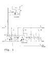
- eine zweite Ausführungsform der Anordnung mit Not-Aus und Resetauslösung allein über den Fernschalter.
- Fig. 1
- a block diagram of the inventive arrangement for safe shutdown of photovoltaic systems;
- Fig. 2
- a first embodiment of the arrangement with a thyristor as a current-carrying semiconductor switch and remote switching device and short circuit and
- Fig. 3
- a second embodiment of the arrangement with emergency stop and Resetauslösung alone via the remote switch.
Wie aus der Darstellung nach
Der stromtragfähige Halbleiterschalter 1 steht mit einer Ansteuerelektronik 3 in Verbindung, die wiederum von einer Not-Aus-Tasteranordnung mit Spannungsanzeige 4 aktiviert wird. Zwischen den in der
Die Schutzfunktion kann über den Lasttrenner 2 manuell zurückgestellt werden. Der Lasttrenner 2 ermöglichen auch eine Trennung der Anlage vom Wechselrichter im Wartungsfall.The protective function can be reset manually via the
Die Ansteuerelektronik 3 sowie der Not-Aus-Taster 4 mit Spannungsanzeige sowie die weiteren Komponenten der erfindungsgemäßen Anordnung sollen mit Rückgriff auf die
Zwischen den Polen 5 des jeweiligen Strings befindet sich ein Thyristor 6 als stromtragfähiger Halbleiterschalter. Der Steuereingang des Thyristors 6 steht mit einem Not-Aus-Schalter 7 in elektrischer Verbindung.The control electronics 3 and the
Between the
Um den Thyristor 6 in den Kurzschlusszustand zu überführen, wird der Not-Aus-Taster 7 geschlossen. In diesem Fall wird in dem Kondensator 8 gespeicherte Energie auf das Gate, d.h. den Steuereingang des Thyristors 6 geführt. Der Kondensator 8 ist über einen Spannungsteiler 9 und eine Zenerdiode 10 mit Energie versorgt, wobei der Spannungsteiler 9 mit der Zenerdiode 10 eine Reihenschaltung bildet und diesbezüglich zwischen den Strangpolen 5 angeordnet ist.In order to convert the
Eine weitere Möglichkeit des Aktivierens der Anordnung zum sicheren Außerbetriebssetzen von Photovoltaikanlagen besteht darin, eine Fernschalteinrichtung zu nutzen.Another way of activating the arrangement for safe shutdown of photovoltaic systems is to use a remote switching device.
Die Fernschalteinrichtung enthält einen externen Not-Aus-Taster 11, eine netzunabhängige Stromversorgung 12 und eine Speichereinrichtung, insbesondere einen Speicherkondensator 13.The remote switching device includes an external
Die netzunabhängige Stromversorgung 12 kann z.B. als Solarzelle ausgebildet sein.The off-
Wird der Not-Aus-Taster 11 betätigt, gelangt galvanisch, über einen Optokoppler 14 getrennt, Energie auf das Gate des Thyristors 6, so dass dieser in den leitfähigen Zustand übergeht. Diesbezüglich steht der Optokoppler 14 ausgangsseitig mit einem Schalttransistor 16 in Verbindung.If the
Wenn der Thyristor sich im leitenden Zustand befindet, zeigt das Voltmeter 17 keine Spannung an. Hierdurch ist überprüfbar, ob das Außerbetriebsetzen erfolgreich war. Der Spannungsmesser 17 ist über eine Spannungsteileranordnung 18 an den Stringpolen 15 angeschlossen.
Eine Z-Diode 19 übernimmt den Schutz des Voltmeters vor Spannungsspitzen.When the thyristor is in the conducting state, the
A zener diode 19 protects the voltmeter from voltage surges.
Um den Kurzschlusszustand wieder aufzuheben, ist dem Thyristor 6 eine weitere Schalteinrichtung 20, insbesondere ausgeführt als Transistor, parallel geschaltet. Der Transistor 20 ist in der Lage, eine kurzzeitige Übernahme des Laststroms des Thyristors zu realisieren, so dass letzterer zurücksetzbar ist. Die Basis des Transistors 20 steht mit einem Reset-Taster 21 in Verbindung. Über den Reset-Taster 21 wird der Kondensator 22 entladen und der Transistor 20 durchgesteuert. Das Aufladen des Kondensators 22 erfolgt über die Spannungsteileranordnung 23 und die Freilaufdiode 24 in Verbindung mit einer spannungsbegrenzenden Diode 25.In order to cancel the short-circuit state again, the
Zum Ausschalten übernimmt also der Transistor 20 kurzzeitig den Laststrom, wenn die Basis des Transistors 20 über den Reset-Schalter 21 angesteuert wird. Der Thyristor 6 geht dann zurück in den Blockierzustand und der Spannungsmesser 17 zeigt die jetzt wieder anliegende volle Strangspannung an.To turn off, therefore, the
Bei der zweiten Ausführungsform der Erfindung gemäß
Wie aus der
Bei der Lösung gemäß dem zweiten Ausführungsbeispiel nach
Zum Erhalt der mit dem Display 17 anzuzeigenden Spannungswerte ist eine Spannungsmessbaugruppe zur Bereitstellung entsprechender digitaler Daten und deren Übertragung über die Busleitung in der Kurzschlussbox vorhanden. Über ein Signal WR disable am Anschlusspunkt 4 kann bei Auswahl des Wechselrichters die Photovoltaikanlage spannungsfrei geschaltet werden, so dass keine Energie mehr in den Wechselrichter eingetragen wird. Ebenso kann am Anschlusspunkt 4 eine Brandmeldeanlage oder andere Meldeeinrichtungen angeschlossen werden, die die Anlage spannungsfrei schalten.In order to obtain the voltage values to be displayed by the
Gemäß Ausführungsbeispiel nach
Zum Wiederinbetriebsetzen ist dem stromtragfähigen Halbleiterschalter, d.h. dem Thyristor 6, ein Transistor 20 dergestalt parallel geschaltet, dass durch kurzzeitige Übernahme des Laststroms der Thyristor wieder zurückgesetzt wird. Hierfür ist an die Basis des Transistors 20 eine Reset-Spannung zum Zurücksetzen anlegbar, wobei diese Spannung aus einem weiteren Kondensator 22 zur Verfügung gestellt ist, welche über eine spannungsbegrenzende Diode 25 durch Anschluss an die Stringpole geladen wird. Ergänzend kann eine Freilaufdiode 24 analog der Ausführungsform nach
Bei einer figürlich nicht dargestellten Ausführungsform besteht die Möglichkeit, das Not-Aus-Signal und/oder das Reset-Signal drahtlos zu übertragen. Hierfür kann der Fernschalter eine integrierte Sendereinheit aufweisen, welche vorzugsweise im sogenannten ISM-Band arbeitet. Die Spannungsversorgung dieser Sendereinrichtung nebst Fernschalter wird über eine separate Solarzelle 12 analog der Ausführungsform nach
Claims (8)
die steuerbare Schalteinrichtung als stromtragfähiger Halbleiterschalter, insbesondere Thyristor ausgebildet ist, an dessen Steuereingang ein Ausschaltsignal anlegbar ist, sowie über einen Spannungsteiler ein Kondensator aus der Photovoltaikanlage mit Energie versorgt wird, wobei der Kondensator mit dem Steuereingang des insbesondere Thyristors verbindbar ist, um den Kurzschlusszustand zu erreichen,
dadurch gekennzeichnet, dass
zum Wiederinbetriebsetzen dem stromtragfähigen Halbleiterschalter ein Transistor parallel geschaltet ist derart, dass durch kurzzeitige Übernahme des Laststroms des stromtragfähigen Halbleiterschalters dieser zurückgesetzt wird und an die Basis des Transistors eine Reset-Spannung zum Zurücksetzen des stromtragfähigen Halbleiterschalters angelegbar ist, wobei diese Spannung aus einem weiteren Kondensator zur Verfügung gestellt ist, welcher über die Stringpole geladen wird.Arrangement for the safe decommissioning of photovoltaic systems, which have a plurality of interconnected at least one string modules, wherein the at least one string can be converted by a controllable switching device in a short circuit state, and
the controllable switching device is designed as a current-carrying semiconductor switch, in particular thyristor, at whose control input a turn-off signal can be applied, and a capacitor from the photovoltaic system is powered via a voltage divider, wherein the capacitor to the control input of the particular thyristor is connectable to the short circuit condition to reach,
characterized in that
For restarting the current-carrying semiconductor switch, a transistor is connected in parallel such that by briefly taking over the load current of the current-carrying semiconductor switch this is reset and to the base of the transistor, a reset voltage for resetting the current-carrying semiconductor switch can be applied, this voltage from a further capacitor for Is provided, which is loaded via the string poles.
dadurch gekennzeichnet, dass
eine Fernschalteinrichtung vorhanden ist, welche eine netzunabhängige Stromversorgung und einen Not-Aus-Taster besitzt, weiterhin die Fernschalteinrichtung galvanisch getrennt mit dem Steuereingang des stromtragfähigen Halbleiterschalters verbunden ist.Arrangement according to claim 1,
characterized in that
a remote switching device is present, which has a mains-independent power supply and an emergency stop button, furthermore the remote switching device is electrically isolated connected to the control input of the current-carrying semiconductor switch.
dadurch gekennzeichnet, dass
für die galvanische Trennung ein Optokoppler vorgesehen ist, der ausgangsseitig mit dem Steuereingang des stromtragfähigen Halbleiterschalters in Verbindung steht.Arrangement according to claim 2,
characterized in that
for galvanic isolation, an optocoupler is provided, the output side of which is in communication with the control input of the current-carrying semiconductor switch.
dadurch gekennzeichnet, dass
die netzunabhängige Stromversorgung eine Solarzelle und einen Speicherkondensator umfasst.Arrangement according to claim 2 or 3,
characterized in that
the off-grid power supply comprises a solar cell and a storage capacitor.
dadurch gekennzeichnet, dass
die Fernschalteinrichtung einen Spannungsmesser aufweist, welcher über einen Spannungsteiler mit den Stringpolen in Verbindung steht.Arrangement according to one of claims 2 to 4,
characterized in that
the remote switching device has a voltmeter which is connected via a voltage divider to the string poles.
dadurch gekennzeichnet, dass
die Elemente der Fernschalteinrichtung in einem gemeinsamen Gehäuse integriert sind.Arrangement according to one of claims 2 to 5,
characterized in that
the elements of the remote switching device are integrated in a common housing.
dadurch gekennzeichnet, dass
zwischen der Photovoltaikanlage und dem jeweiligen zugehörigen Wechselrichter ein Lasttrenner geschaltet ist.Arrangement according to one of the preceding claims,
characterized in that
a load disconnector is connected between the photovoltaic system and the respective associated inverter.
dadurch gekennzeichnet, dass
der weitere Kondensator über eine spannungsbegrenzende Diode sowie einen Spannungsteiler und eine Freilaufdiode durch Anschluss an die Stringpole geladen wird.Arrangement according to claim 1,
characterized in that
the additional capacitor is charged via a voltage-limiting diode and a voltage divider and a freewheeling diode by connecting to the string poles.
Applications Claiming Priority (2)
| Application Number | Priority Date | Filing Date | Title |
|---|---|---|---|
| DE102010047935 | 2010-10-08 | ||
| DE201010049293 DE102010049293B3 (en) | 2010-09-21 | 2010-10-22 | Arrangement for safe shutdown of photovoltaic system attached to building, charges voltage-limiting diode, voltage divider and freewheeling diode connected to string poles by terminal |
Publications (2)
| Publication Number | Publication Date |
|---|---|
| EP2439829A2 true EP2439829A2 (en) | 2012-04-11 |
| EP2439829A3 EP2439829A3 (en) | 2012-12-05 |
Family
ID=44763855
Family Applications (1)
| Application Number | Title | Priority Date | Filing Date |
|---|---|---|---|
| EP11179236A Withdrawn EP2439829A3 (en) | 2010-10-08 | 2011-08-30 | Assembly for secure deactivation of photovoltaic assemblies |
Country Status (1)
| Country | Link |
|---|---|
| EP (1) | EP2439829A3 (en) |
Cited By (2)
| Publication number | Priority date | Publication date | Assignee | Title |
|---|---|---|---|---|
| CN108666978A (en) * | 2018-06-29 | 2018-10-16 | 江苏集能易新能源技术有限公司 | A kind of photovoltaic switching off device bleeder circuit |
| CN113726135A (en) * | 2021-09-24 | 2021-11-30 | 桂林电子科技大学 | Silicon controlled switch circuit switched off by shunting of MOS (metal oxide semiconductor) tube |
Citations (4)
| Publication number | Priority date | Publication date | Assignee | Title |
|---|---|---|---|---|
| DE4041672A1 (en) | 1990-12-22 | 1992-06-25 | Zsw | Monitoring unit for DC circuit for photovoltaic prodn. plants - which with line interference occuring within monitored stretch, current flow through monitored line section is interrupted using two monitoring lines |
| US20020014262A1 (en) | 2000-07-10 | 2002-02-07 | Masaaki Matsushita | Photovoltaic power generation systems and methods of controlling photovoltaic power generation systems |
| EP1720241A2 (en) | 2005-04-18 | 2006-11-08 | Beck Energy GmbH | Photovoltaic generator with thermal switch |
| DE102005018173B4 (en) | 2005-04-19 | 2009-05-14 | Swiontek, Karl, Dipl.-Ing. | Switching device for safe interruption of operation of photovoltaic systems |
Family Cites Families (2)
| Publication number | Priority date | Publication date | Assignee | Title |
|---|---|---|---|---|
| DE102008052037B3 (en) * | 2008-10-16 | 2010-04-08 | Moeller Gmbh | solar module |
| WO2010078303A2 (en) * | 2008-12-29 | 2010-07-08 | Atonometrics, Inc. | Electrical safety shutoff system and devices for photovoltaic modules |
-
2011
- 2011-08-30 EP EP11179236A patent/EP2439829A3/en not_active Withdrawn
Patent Citations (4)
| Publication number | Priority date | Publication date | Assignee | Title |
|---|---|---|---|---|
| DE4041672A1 (en) | 1990-12-22 | 1992-06-25 | Zsw | Monitoring unit for DC circuit for photovoltaic prodn. plants - which with line interference occuring within monitored stretch, current flow through monitored line section is interrupted using two monitoring lines |
| US20020014262A1 (en) | 2000-07-10 | 2002-02-07 | Masaaki Matsushita | Photovoltaic power generation systems and methods of controlling photovoltaic power generation systems |
| EP1720241A2 (en) | 2005-04-18 | 2006-11-08 | Beck Energy GmbH | Photovoltaic generator with thermal switch |
| DE102005018173B4 (en) | 2005-04-19 | 2009-05-14 | Swiontek, Karl, Dipl.-Ing. | Switching device for safe interruption of operation of photovoltaic systems |
Cited By (3)
| Publication number | Priority date | Publication date | Assignee | Title |
|---|---|---|---|---|
| CN108666978A (en) * | 2018-06-29 | 2018-10-16 | 江苏集能易新能源技术有限公司 | A kind of photovoltaic switching off device bleeder circuit |
| CN108666978B (en) * | 2018-06-29 | 2024-02-02 | 江苏集能易新能源技术有限公司 | Voltage dividing circuit of photovoltaic turnoff device |
| CN113726135A (en) * | 2021-09-24 | 2021-11-30 | 桂林电子科技大学 | Silicon controlled switch circuit switched off by shunting of MOS (metal oxide semiconductor) tube |
Also Published As
| Publication number | Publication date |
|---|---|
| EP2439829A3 (en) | 2012-12-05 |
Similar Documents
| Publication | Publication Date | Title |
|---|---|---|
| EP2745327B1 (en) | Socket for a solar panel with a protective circuit | |
| EP2726889B1 (en) | Photovoltaic module | |
| DE102009022508A1 (en) | Safety switchgear for solar systems | |
| EP2567405A1 (en) | Method for limiting the generator voltage of a photovoltaic installation in case of danger and photovoltaic installation | |
| EP2282388A1 (en) | Device for feeding in electrical energy of a number of strings of photovoltaic modules in an electricity network | |
| EP2815434B1 (en) | Switching-off of solar modules | |
| DE102015102468B3 (en) | Emergency power system and grounding device for a network backup system | |
| DE102010049293B3 (en) | Arrangement for safe shutdown of photovoltaic system attached to building, charges voltage-limiting diode, voltage divider and freewheeling diode connected to string poles by terminal | |
| WO2015059195A1 (en) | Inverter system and pv system | |
| EP2960945A2 (en) | Generator connection cabinet connected with a central inverter for arc free switching of PV-modules | |
| EP3565074A1 (en) | Coupling circuit with switching function for coupling an insulation monitoring device to an ungrounded power supply system | |
| DE102010037760B4 (en) | Device and method for voltage isolation of electrical, running in a building or complex of buildings lines of a photovoltaic system, use of the device and system with the device and a photovoltaic system | |
| DE102011018972B4 (en) | Solar module protection device | |
| EP2439829A2 (en) | Assembly for secure deactivation of photovoltaic assemblies | |
| AT519847B1 (en) | Electrical switchgear | |
| EP2500208B2 (en) | Protective circuit assembly | |
| EP2899738B1 (en) | External driving of an electromagnetic trigger | |
| DE102014201503A1 (en) | Electrical protection arrangement for an electrical installation and associated method | |
| DE102015115284B3 (en) | Protective device for an electrical power supply device and electrical power supply device with such a protective device | |
| EP2608343B1 (en) | Power supply | |
| DE102010004395A1 (en) | Switch arrangement for protecting photovoltaic system, has switch device forming bypass to activate protection device lying in flow direction of short circuit current during activation drop of protection device | |
| EP2463914A1 (en) | Safety device for photovoltaic assemblies | |
| BE1024324B1 (en) | Photovoltaic system, DC hybrid switching device, use and method for switching a photovoltaic string on and off | |
| DE102017124567B4 (en) | Battery system, local power supply and disconnector | |
| DE202012000324U1 (en) | Arrangement for safe disconnection of the DC side of a photovoltaic system |
Legal Events
| Date | Code | Title | Description |
|---|---|---|---|
| AK | Designated contracting states |
Kind code of ref document: A2 Designated state(s): AL AT BE BG CH CY CZ DE DK EE ES FI FR GB GR HR HU IE IS IT LI LT LU LV MC MK MT NL NO PL PT RO RS SE SI SK SM TR |
|
| AX | Request for extension of the european patent |
Extension state: BA ME |
|
| PUAI | Public reference made under article 153(3) epc to a published international application that has entered the european phase |
Free format text: ORIGINAL CODE: 0009012 |
|
| PUAL | Search report despatched |
Free format text: ORIGINAL CODE: 0009013 |
|
| AK | Designated contracting states |
Kind code of ref document: A3 Designated state(s): AL AT BE BG CH CY CZ DE DK EE ES FI FR GB GR HR HU IE IS IT LI LT LU LV MC MK MT NL NO PL PT RO RS SE SI SK SM TR |
|
| AX | Request for extension of the european patent |
Extension state: BA ME |
|
| RIC1 | Information provided on ipc code assigned before grant |
Ipc: H02H 7/20 20060101AFI20121029BHEP Ipc: H01L 31/02 20060101ALI20121029BHEP |
|
| STAA | Information on the status of an ep patent application or granted ep patent |
Free format text: STATUS: THE APPLICATION IS DEEMED TO BE WITHDRAWN |
|
| 18D | Application deemed to be withdrawn |
Effective date: 20130606 |