EP2439448A1 - Method and device for detecting liquid fuel leakage in a gas turbine system combustion assembly - Google Patents
Method and device for detecting liquid fuel leakage in a gas turbine system combustion assembly Download PDFInfo
- Publication number
- EP2439448A1 EP2439448A1 EP11175318A EP11175318A EP2439448A1 EP 2439448 A1 EP2439448 A1 EP 2439448A1 EP 11175318 A EP11175318 A EP 11175318A EP 11175318 A EP11175318 A EP 11175318A EP 2439448 A1 EP2439448 A1 EP 2439448A1
- Authority
- EP
- European Patent Office
- Prior art keywords
- diffusion
- main body
- along
- test fluid
- diffusion section
- Prior art date
- Legal status (The legal status is an assumption and is not a legal conclusion. Google has not performed a legal analysis and makes no representation as to the accuracy of the status listed.)
- Withdrawn
Links
Images


Classifications
-
- F—MECHANICAL ENGINEERING; LIGHTING; HEATING; WEAPONS; BLASTING
- F23—COMBUSTION APPARATUS; COMBUSTION PROCESSES
- F23D—BURNERS
- F23D11/00—Burners using a direct spraying action of liquid droplets or vaporised liquid into the combustion space
- F23D11/36—Details
- F23D11/38—Nozzles; Cleaning devices therefor
-
- F—MECHANICAL ENGINEERING; LIGHTING; HEATING; WEAPONS; BLASTING
- F02—COMBUSTION ENGINES; HOT-GAS OR COMBUSTION-PRODUCT ENGINE PLANTS
- F02C—GAS-TURBINE PLANTS; AIR INTAKES FOR JET-PROPULSION PLANTS; CONTROLLING FUEL SUPPLY IN AIR-BREATHING JET-PROPULSION PLANTS
- F02C7/00—Features, components parts, details or accessories, not provided for in, or of interest apart form groups F02C1/00 - F02C6/00; Air intakes for jet-propulsion plants
- F02C7/22—Fuel supply systems
-
- F—MECHANICAL ENGINEERING; LIGHTING; HEATING; WEAPONS; BLASTING
- F23—COMBUSTION APPARATUS; COMBUSTION PROCESSES
- F23K—FEEDING FUEL TO COMBUSTION APPARATUS
- F23K5/00—Feeding or distributing other fuel to combustion apparatus
- F23K5/02—Liquid fuel
- F23K5/14—Details thereof
- F23K5/16—Safety devices
-
- F—MECHANICAL ENGINEERING; LIGHTING; HEATING; WEAPONS; BLASTING
- F23—COMBUSTION APPARATUS; COMBUSTION PROCESSES
- F23R—GENERATING COMBUSTION PRODUCTS OF HIGH PRESSURE OR HIGH VELOCITY, e.g. GAS-TURBINE COMBUSTION CHAMBERS
- F23R3/00—Continuous combustion chambers using liquid or gaseous fuel
- F23R3/28—Continuous combustion chambers using liquid or gaseous fuel characterised by the fuel supply
- F23R3/286—Continuous combustion chambers using liquid or gaseous fuel characterised by the fuel supply having fuel-air premixing devices
-
- G—PHYSICS
- G01—MEASURING; TESTING
- G01M—TESTING STATIC OR DYNAMIC BALANCE OF MACHINES OR STRUCTURES; TESTING OF STRUCTURES OR APPARATUS, NOT OTHERWISE PROVIDED FOR
- G01M3/00—Investigating fluid-tightness of structures
- G01M3/02—Investigating fluid-tightness of structures by using fluid or vacuum
- G01M3/022—Test plugs for closing off the end of a pipe
-
- G—PHYSICS
- G01—MEASURING; TESTING
- G01M—TESTING STATIC OR DYNAMIC BALANCE OF MACHINES OR STRUCTURES; TESTING OF STRUCTURES OR APPARATUS, NOT OTHERWISE PROVIDED FOR
- G01M3/00—Investigating fluid-tightness of structures
- G01M3/02—Investigating fluid-tightness of structures by using fluid or vacuum
- G01M3/04—Investigating fluid-tightness of structures by using fluid or vacuum by detecting the presence of fluid at the leakage point
- G01M3/12—Investigating fluid-tightness of structures by using fluid or vacuum by detecting the presence of fluid at the leakage point by observing elastic covers or coatings, e.g. soapy water
- G01M3/14—Investigating fluid-tightness of structures by using fluid or vacuum by detecting the presence of fluid at the leakage point by observing elastic covers or coatings, e.g. soapy water for pipes, cables or tubes; for pipe joints or seals; for valves; for welds; for containers, e.g. radiators
-
- F—MECHANICAL ENGINEERING; LIGHTING; HEATING; WEAPONS; BLASTING
- F05—INDEXING SCHEMES RELATING TO ENGINES OR PUMPS IN VARIOUS SUBCLASSES OF CLASSES F01-F04
- F05D—INDEXING SCHEME FOR ASPECTS RELATING TO NON-POSITIVE-DISPLACEMENT MACHINES OR ENGINES, GAS-TURBINES OR JET-PROPULSION PLANTS
- F05D2260/00—Function
- F05D2260/80—Diagnostics
-
- F—MECHANICAL ENGINEERING; LIGHTING; HEATING; WEAPONS; BLASTING
- F05—INDEXING SCHEMES RELATING TO ENGINES OR PUMPS IN VARIOUS SUBCLASSES OF CLASSES F01-F04
- F05D—INDEXING SCHEME FOR ASPECTS RELATING TO NON-POSITIVE-DISPLACEMENT MACHINES OR ENGINES, GAS-TURBINES OR JET-PROPULSION PLANTS
- F05D2260/00—Function
- F05D2260/83—Testing, e.g. methods, components or tools therefor
-
- F—MECHANICAL ENGINEERING; LIGHTING; HEATING; WEAPONS; BLASTING
- F23—COMBUSTION APPARATUS; COMBUSTION PROCESSES
- F23D—BURNERS
- F23D2900/00—Special features of, or arrangements for burners using fluid fuels or solid fuels suspended in a carrier gas
- F23D2900/00008—Burner assemblies with diffusion and premix modes, i.e. dual mode burners
-
- F—MECHANICAL ENGINEERING; LIGHTING; HEATING; WEAPONS; BLASTING
- F23—COMBUSTION APPARATUS; COMBUSTION PROCESSES
- F23K—FEEDING FUEL TO COMBUSTION APPARATUS
- F23K2300/00—Pretreatment and supply of liquid fuel
- F23K2300/20—Supply line arrangements
- F23K2300/206—Control devices
-
- F—MECHANICAL ENGINEERING; LIGHTING; HEATING; WEAPONS; BLASTING
- F23—COMBUSTION APPARATUS; COMBUSTION PROCESSES
- F23K—FEEDING FUEL TO COMBUSTION APPARATUS
- F23K2900/00—Special features of, or arrangements for fuel supplies
- F23K2900/05001—Control or safety devices in gaseous or liquid fuel supply lines
-
- F—MECHANICAL ENGINEERING; LIGHTING; HEATING; WEAPONS; BLASTING
- F23—COMBUSTION APPARATUS; COMBUSTION PROCESSES
- F23N—REGULATING OR CONTROLLING COMBUSTION
- F23N2231/00—Fail safe
- F23N2231/18—Detecting fluid leaks
-
- F—MECHANICAL ENGINEERING; LIGHTING; HEATING; WEAPONS; BLASTING
- F23—COMBUSTION APPARATUS; COMBUSTION PROCESSES
- F23R—GENERATING COMBUSTION PRODUCTS OF HIGH PRESSURE OR HIGH VELOCITY, e.g. GAS-TURBINE COMBUSTION CHAMBERS
- F23R2900/00—Special features of, or arrangements for continuous combustion chambers; Combustion processes therefor
- F23R2900/00019—Repairing or maintaining combustion chamber liners or subparts
Definitions
- the present invention relates to a method and device for detecting liquid fuel leakage in a gas turbine system combustion assembly.
- Combustion assemblies of known type comprise a combustion chamber and a feeding circuit of the combustion chamber.
- Gaseous fuel leakages are normally indicated by specific gas detectors installed in the enclosure which encloses the combustion assembly during operation.
- the detector sends an alarm signal as soon as a concentration of gas higher than the danger threshold is detected.
- the protection system causes the gas turbine to shut down if the concentration increases or the cause of the leakage is not eliminated.
- liquid fuel which flow out due to a leakage often reaches the hot parts of the system, which are thermally insulated by means of pads made of insulating fibers. If the liquid fuel penetrates in these pads and reaches the metallic parts of the machine, it can catch fire and the fire which develops is difficult to control because the pads are soaked in liquid fuel.
- the present invention relates to a method of detecting liquid fuel leakages in a gas turbine system combustion assembly, the combustion assembly comprising a combustion chamber equipped with a plurality of burner assemblies, each of which comprises a diffusion nozzle and at least one premix nozzle, and a feed circuit, which feeds liquid fuel to the combustion chamber and comprises a diffusion section for supplying the diffusion nozzles, and a premix section for supplying the premix nozzles; the method comprising the steps of:
- the present invention relates to a device for detecting liquid fuel leakages in a gas turbine system combustion assembly, the combustion assembly comprising a combustion chamber equipped with a plurality of burner assemblies, each comprising a diffusion nozzle and at least one premix nozzle, and a feed circuit, which feeds liquid fuel to the combustion chamber and comprises a diffusion section for supplying the diffusion nozzles, and a premix section for supplying the premix nozzles, the device comprising at least one stopper for sealing the diffusion nozzle of the burner assembly.
- reference number 1 indicates a combustion assembly comprising a combustion chamber 2 and a feeding circuit 3 for feeding liquid fuel to the combustion chamber 2.
- the combustion chamber 2 is preferably of the annular type and comprises a plurality of burners 5 (diagrammatically shown in figure 1 with a box) arranged along a circular path in proximity of a peripheral annular edge 6 of the combustion chamber 2.
- burners 5 there are twenty-four burners 5 in the non-limiting example described and shown herein.
- Each burner assembly 5 comprises a liquid fuel burner 8 connected to the fuel feeding circuit 3.
- the liquid fuel normally used is diesel.
- the burner assembly 5 also comprises a gas burner (not shown in the accompanying figures).
- the liquid fuel burner 8 comprises a diffusion burner member 10 and a premix burner member 11.
- the diffusion burner member 10 comprises a delivery pipe 12, a return pipe 13, an intermediate chamber 14 and a diffusion nozzle 15.
- the premix burner member 11 comprises a main annular pipe 16 and a plurality of premix nozzles 17.
- a main annular pipe 16 and a plurality of premix nozzles 17.
- the feeding circuit 3 comprises a diffusion section 19 connected to the diffusion burner members 10 and a premix section 20 connected to the premix burner members 11.
- the diffusion section 19 comprises a diesel delivery line 21 and a diesel return line 22.
- the diesel delivery line 21 is provided with a delivery valve 18, a toroidal manifold 23 and a plurality of diesel delivery pipes 24 for connecting the manifold 23 to the respective diffusion burners 10.
- Each diesel delivery pipe 24 is connected to the manifold 23 by means of a head connector 26 and to the diffusion burner member 10 by means of a tail connector 27.
- the diesel return line 22 is provided with a respective toroidal manifold 28a and a plurality of a diesel return pipes 28b for connecting the diffusion burner members 10 to the manifold 28a, a return valve 29a and a stop valve 29b.
- Each diesel return pipe 28b is connected to the manifold 28a by means of a head connector 30 and to the diffusion burner member 10 by means of a tail connector 31.
- the premix section 20 comprises a premix delivery line 34, provided with a respective toroidal manifold 35 and a plurality of tubes 36 which connect the manifold 35 to the premix burner members 11.
- Each pipe 36 is connected to the manifold 35 by means of a head connector 39 and to the premix burner member 11 by means of a tail connector 40.
- reference numeral 50 indicates a device for detecting leakages of liquid fuel in a burner assembly of a gas turbine system according to the present invention.
- the device 50 comprises an injection assembly 51 for injecting a test fluid into a feed circuit and a plurality of stopper members 52 (of which only one is visible in figures 3 and 4 ).
- the injection assembly 51 is connected to the diesel delivery line 21 upstream of the manifold 23 and comprises a tank 54 containing the test fluid, a pump 55 configured to take the test fluid from the tank and introduce it into the diesel delivery line 21 and a valve 56, arranged upstream of the pump 55.
- the pump 55 is preferably a centrifugal pump configured to pump the test fluid at a pressure comprised between roughly 1 and 20 bars.
- the test fluid is preferably water.
- the test fluid is liquid nitrogen (pumped by the pump 55 at a roughly 20 bars).
- the injection assembly 51 also comprises an air compressor 57.
- the compressor 57 is portable and configured to compress air at roughly 7 bars.
- the compressor is not present and the compressed air is taken directly by the gas turbine system.
- each stopper member 52 is adapted to be inserted in the respective diffusion nozzle 15 to shut it.
- Each stopper member 52 comprises a main body 59 and a moveable member 60.
- the main body 59 extends along a longitudinal axis A, is essentially cylinder-shaped and is made of deformable material.
- the main body 59 is an appropriately shaped pipe made of silicone rubber and provided with a central hole 61, which extends along the longitudinal axis A.
- the moveable member 60 is partially inserted in the central hole 61 of the main body 59 and has a first end 62 provided with a head 63 and a second end 64 provided with an eyelet 65.
- the head 63 and eyelet 65 are arranged outside the central hole 61.
- the section of the head 63 is larger than the central hole 61 and smaller than the open section of the diffusion nozzle 15, so as to be able to enter into the intermediate chamber 14 through the diffusion nozzle 10.
- the head 63 has a substantially spherical shape.
- the eyelet 65 is preferably coupled to a recovery member 66 to prevent the stopper member 52 from being lost in the combustion chamber 2 in case of ejection.
- the recovery member 66 is a wire.
- the moveable member 60 is mobile between an open position and a closed position.
- the head 63 In the open position, shown in figure 3 , the head 63 is not in contact with main body 59 and the main body 59 is not deformed.
- the head 63 is arranged abuttingly against the main body 59 to shut the central hole 61 and deform the main body 59 so that it adapts to the profile of the diffusion nozzle 15 and shuts it.
- the head 63 is further pressed against the main body 59 so as to guarantee an optimal shutting of the diffusion nozzle 15.
- the method for detecting leakages of liquid fuel from a combustion assembly 2 contemplates detecting leakages along the diffusion section 19 and then detecting leakages along the premix section 20.
- the step of detecting leakages along the diffusion section 19 essentially includes sealing all diffusion nozzles 15 by means of respective stopper members 52, feeding the pressurized test liquid to the diesel delivery line 21 by means of the pump 55; and detecting the leakages along the diffusion section 19.
- the step of sealing the diffusion nozzles 15 includes inserting shutter elements 52 in the respective diffusion nozzles 15 ( figure 3 ) and arranging them in the closed position ( figure 4 ).
- the step of feeding the test fluid contemplates closing the valves 29a, 29b and 18, opening the valve 56 and activating the pump 55.
- test fluid is pumped at a pressure comprised between roughly 7 and roughly 20 bars along the diffusion section 19.
- the step of detecting the leakages includes applying a detecting fluid in the critical points of the diffusion section 19 and monitoring the diffusion section 19 while the pressurized test fluid is fed to the diesel delivery line 21.
- Critical points are the head connectors 26, 30, the tail connectors 27 31 and the threaded connections of the diffusion section 19.
- the detecting fluid is preferably a surfactant which generates bubbles when invested by a high pressure fluid.
- the pressurized test fluid invests the detector fluid creating bubbles.
- the method according to the present invention includes carrying out a tightness test with low pressure compressed air (up to roughly 7 bars) before testing with test fluid at higher pressures (more than 30 bars).
- the method includes sealing all the diffusion nozzles 15 by means of the respective stopper elements 52, feeding compressed air to the diesel delivery line 21 by means of the compressor 57, detecting the leakages of air along the diffusion section 19; feeding the pressurized test fluid to the diesel delivery line 21 by means of the pump 55 and detecting leakage of fluid along the diffusion section 19.
- the method detects the larger leakages during the low pressure air test, thus avoiding to flood the enclosure containing the combustion assembly 2 with the test fluid.
- the method includes carrying out the test once again with a high pressure test fluid (higher than roughly 15 bars) in order to identify the less evident leakages.
- the step of detecting leakages along the premix section 20 substantially includes disconnecting all head connectors 39 of each pipe 36, connecting the head connectors 39 to the compressor 57 (preferably one at a time) and feeding an air flow sufficient to pressurize each pipe 36 at least at 2 bars; detecting possible leakages at the respective tail connector 40 by means of a detector fluid, and finally reconnecting the head connector 40 to the connector 35.
- the method includes carrying out a test to verify the tightness of the head connectors 39.
- a test is carried out (with the gas turbine running and diffusing diesel) by feeding the premix line 20 with a pressurized fluid (preferably purging water or washing water) and detecting the leakages at the head connectors 39 with a detecting fluid or simply by means of a visual check.
- a pressurized fluid preferably purging water or washing water
- the method and device according to the present invention are simple and reliably detect the leakages of the feeding circuit 3 thus reducing the risk of fire.
Landscapes
- Engineering & Computer Science (AREA)
- Chemical & Material Sciences (AREA)
- Combustion & Propulsion (AREA)
- Mechanical Engineering (AREA)
- General Engineering & Computer Science (AREA)
- Physics & Mathematics (AREA)
- General Physics & Mathematics (AREA)
- Examining Or Testing Airtightness (AREA)
Abstract
A method of detecting liquid fuel leakage in a gas turbine system combustion assembly (1) provided with a combustion chamber (2) having a plurality of diffusion nozzles (15) and a feed circuit (3), which feeds liquid fuel to the combustion chamber (2) and comprises a diffusion section (19) for supplying the diffusion nozzles (15), includes:
- sealing the diffusion nozzle (15) of each burner assembly (5);
- feeding a pressurized test fluid along the diffusion section (19);
- checking for test fluid leakage along the diffusion section (19).
- sealing the diffusion nozzle (15) of each burner assembly (5);
- feeding a pressurized test fluid along the diffusion section (19);
- checking for test fluid leakage along the diffusion section (19).
Description
- The present invention relates to a method and device for detecting liquid fuel leakage in a gas turbine system combustion assembly.
- Combustion assemblies of known type comprise a combustion chamber and a feeding circuit of the combustion chamber.
- In the gas turbine system sector monitoring the leakages of fuel is of crucial importance.
- Gaseous fuel leakages are normally indicated by specific gas detectors installed in the enclosure which encloses the combustion assembly during operation. The detector sends an alarm signal as soon as a concentration of gas higher than the danger threshold is detected. The protection system causes the gas turbine to shut down if the concentration increases or the cause of the leakage is not eliminated.
- No reliable methods are available for detecting leakage of liquid fuel.
- However, the leakages of liquid fuel are very dangerous. Liquid fuel which flow out due to a leakage often reaches the hot parts of the system, which are thermally insulated by means of pads made of insulating fibers. If the liquid fuel penetrates in these pads and reaches the metallic parts of the machine, it can catch fire and the fire which develops is difficult to control because the pads are soaked in liquid fuel.
- Controlling the tightness of pipes in which liquid fuel flows is thus a need highly felt by manufacturers and users.
- It is thus an object of the present invention to provide a method for detecting liquid fuel leakage in a gas turbine system combustion assembly which is simple and reliable.
- In accordance with such an object, the present invention relates to a method of detecting liquid fuel leakages in a gas turbine system combustion assembly, the combustion assembly comprising a combustion chamber equipped with a plurality of burner assemblies, each of which comprises a diffusion nozzle and at least one premix nozzle, and a feed circuit, which feeds liquid fuel to the combustion chamber and comprises a diffusion section for supplying the diffusion nozzles, and a premix section for supplying the premix nozzles;
the method comprising the steps of: - sealing the diffusion nozzle of each burner assembly;
- feeding a pressurized test fluid along the diffusion section;
- checking for test fluid leakage along the diffusion section.
- It is thus a further object of the present invention to provide a device for detecting liquid fuel leakages in a gas turbine system combustion assembly which is simple and reliable.
- In accordance with such objects, the present invention relates to a device for detecting liquid fuel leakages in a gas turbine system combustion assembly, the combustion assembly comprising a combustion chamber equipped with a plurality of burner assemblies, each comprising a diffusion nozzle and at least one premix nozzle, and a feed circuit, which feeds liquid fuel to the combustion chamber and comprises a diffusion section for supplying the diffusion nozzles, and a premix section for supplying the premix nozzles, the device comprising at least one stopper for sealing the diffusion nozzle of the burner assembly.
- Further features and advantages of the present invention will be apparent from the following description of a non-limitative embodiment thereof, with reference to the figures in the accompanying drawings, in which:
-
figure 1 is a diagrammatic view of a combustion assembly of a gas turbine system; -
figure 2 is a perspective view, with parts in section and parts removed for clarity, of a detail of the combustion assembly infigure 1 ; -
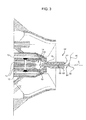
figure 3 is a diagrammatic view with parts in section and parts removed for clarity of a detail of the device for detecting leakages of liquid fuel in a combustion assembly of a gas turbine system in a first operating position; -
figure 4 is a diagrammatic view, with parts in section and parts removed for clarity, of the detail infigure 3 in a second operative position. - In
figure 1 , reference number 1 indicates a combustion assembly comprising acombustion chamber 2 and afeeding circuit 3 for feeding liquid fuel to thecombustion chamber 2. - The
combustion chamber 2 is preferably of the annular type and comprises a plurality of burners 5 (diagrammatically shown infigure 1 with a box) arranged along a circular path in proximity of a peripheral annular edge 6 of thecombustion chamber 2. - There are twenty-four
burners 5 in the non-limiting example described and shown herein. - Each
burner assembly 5 comprises aliquid fuel burner 8 connected to thefuel feeding circuit 3. - The liquid fuel normally used is diesel.
- Preferably, the
burner assembly 5 also comprises a gas burner (not shown in the accompanying figures). - With reference to
figure 2 , theliquid fuel burner 8 comprises adiffusion burner member 10 and apremix burner member 11. Thediffusion burner member 10 comprises adelivery pipe 12, areturn pipe 13, anintermediate chamber 14 and adiffusion nozzle 15. - The
premix burner member 11 comprises a mainannular pipe 16 and a plurality ofpremix nozzles 17. In the example described and illustrated herein, there are eighteen/twenty premix nozzles 17 (of which only two are shown in the accompanying figures). - With reference to
figure 1 , thefeeding circuit 3 comprises adiffusion section 19 connected to thediffusion burner members 10 and apremix section 20 connected to thepremix burner members 11. - The
diffusion section 19 comprises adiesel delivery line 21 and a diesel return line 22. - The
diesel delivery line 21 is provided with adelivery valve 18, atoroidal manifold 23 and a plurality ofdiesel delivery pipes 24 for connecting themanifold 23 to therespective diffusion burners 10. - Each
diesel delivery pipe 24 is connected to themanifold 23 by means of ahead connector 26 and to thediffusion burner member 10 by means of atail connector 27. - The diesel return line 22 is provided with a respective
toroidal manifold 28a and a plurality of adiesel return pipes 28b for connecting thediffusion burner members 10 to themanifold 28a, areturn valve 29a and astop valve 29b. - Each
diesel return pipe 28b is connected to themanifold 28a by means of ahead connector 30 and to thediffusion burner member 10 by means of a tail connector 31. - The
premix section 20 comprises apremix delivery line 34, provided with a respectivetoroidal manifold 35 and a plurality oftubes 36 which connect themanifold 35 to thepremix burner members 11. - Each
pipe 36 is connected to themanifold 35 by means of ahead connector 39 and to thepremix burner member 11 by means of atail connector 40. - In
figure 1 ,reference numeral 50 indicates a device for detecting leakages of liquid fuel in a burner assembly of a gas turbine system according to the present invention. - The
device 50 comprises aninjection assembly 51 for injecting a test fluid into a feed circuit and a plurality of stopper members 52 (of which only one is visible infigures 3 and4 ). - The
injection assembly 51 is connected to thediesel delivery line 21 upstream of themanifold 23 and comprises atank 54 containing the test fluid, apump 55 configured to take the test fluid from the tank and introduce it into thediesel delivery line 21 and avalve 56, arranged upstream of thepump 55. - The
pump 55 is preferably a centrifugal pump configured to pump the test fluid at a pressure comprised between roughly 1 and 20 bars. - The test fluid is preferably water.
- According to a variant of the present invention, the test fluid is liquid nitrogen (pumped by the
pump 55 at a roughly 20 bars). - Preferably, the
injection assembly 51 also comprises anair compressor 57. In the non-limitative example described and illustrated herein, thecompressor 57 is portable and configured to compress air at roughly 7 bars. - According to a variant (not shown) of the present invention, the compressor is not present and the compressed air is taken directly by the gas turbine system.
- With reference to
figure 3 , eachstopper member 52 is adapted to be inserted in therespective diffusion nozzle 15 to shut it. - Each
stopper member 52 comprises amain body 59 and amoveable member 60. - The
main body 59 extends along a longitudinal axis A, is essentially cylinder-shaped and is made of deformable material. In particular, themain body 59 is an appropriately shaped pipe made of silicone rubber and provided with acentral hole 61, which extends along the longitudinal axis A. - The
moveable member 60 is partially inserted in thecentral hole 61 of themain body 59 and has afirst end 62 provided with ahead 63 and asecond end 64 provided with aneyelet 65. - The
head 63 andeyelet 65 are arranged outside thecentral hole 61. - In particular, the section of the
head 63 is larger than thecentral hole 61 and smaller than the open section of thediffusion nozzle 15, so as to be able to enter into theintermediate chamber 14 through thediffusion nozzle 10. - Preferably, the
head 63 has a substantially spherical shape. - The
eyelet 65 is preferably coupled to arecovery member 66 to prevent thestopper member 52 from being lost in thecombustion chamber 2 in case of ejection. In the non-limitative example described and illustrated herein, therecovery member 66 is a wire. - The
moveable member 60 is mobile between an open position and a closed position. - In the open position, shown in
figure 3 , thehead 63 is not in contact withmain body 59 and themain body 59 is not deformed. - In the closed position, shown in
figure 4 , thehead 63 is arranged abuttingly against themain body 59 to shut thecentral hole 61 and deform themain body 59 so that it adapts to the profile of thediffusion nozzle 15 and shuts it. - The sum of the thickness of the
head 63 and of themain body 59 so that the diameter of thestopper element 52 is larger than that of thediffusion nozzle 10 and completely shuts it. - Furthermore, if a pressure increase occurs within the
intermediate chamber 14, thehead 63 is further pressed against themain body 59 so as to guarantee an optimal shutting of thediffusion nozzle 15. - With reference to
figure 1 , the method for detecting leakages of liquid fuel from acombustion assembly 2 contemplates detecting leakages along thediffusion section 19 and then detecting leakages along thepremix section 20. - The step of detecting leakages along the
diffusion section 19 essentially includes sealing alldiffusion nozzles 15 by means ofrespective stopper members 52, feeding the pressurized test liquid to thediesel delivery line 21 by means of thepump 55; and detecting the leakages along thediffusion section 19. - The step of sealing the
diffusion nozzles 15 includes insertingshutter elements 52 in the respective diffusion nozzles 15 (figure 3 ) and arranging them in the closed position (figure 4 ). - The step of feeding the test fluid contemplates closing the
valves valve 56 and activating thepump 55. - The test fluid is pumped at a pressure comprised between roughly 7 and roughly 20 bars along the
diffusion section 19. - The step of detecting the leakages includes applying a detecting fluid in the critical points of the
diffusion section 19 and monitoring thediffusion section 19 while the pressurized test fluid is fed to thediesel delivery line 21. Critical points are thehead connectors tail connectors 27 31 and the threaded connections of thediffusion section 19. - The detecting fluid is preferably a surfactant which generates bubbles when invested by a high pressure fluid. In case of leakage, indeed, the pressurized test fluid invests the detector fluid creating bubbles.
- Preferably, the method according to the present invention includes carrying out a tightness test with low pressure compressed air (up to roughly 7 bars) before testing with test fluid at higher pressures (more than 30 bars).
- In essence, the method includes sealing all the
diffusion nozzles 15 by means of therespective stopper elements 52, feeding compressed air to thediesel delivery line 21 by means of thecompressor 57, detecting the leakages of air along thediffusion section 19; feeding the pressurized test fluid to thediesel delivery line 21 by means of thepump 55 and detecting leakage of fluid along thediffusion section 19. - In this manner, the method detects the larger leakages during the low pressure air test, thus avoiding to flood the enclosure containing the
combustion assembly 2 with the test fluid. - Subsequently, after having repaired the larger leakages, the method includes carrying out the test once again with a high pressure test fluid (higher than roughly 15 bars) in order to identify the less evident leakages.
- The step of detecting leakages along the
premix section 20 substantially includes disconnecting allhead connectors 39 of eachpipe 36, connecting thehead connectors 39 to the compressor 57 (preferably one at a time) and feeding an air flow sufficient to pressurize eachpipe 36 at least at 2 bars; detecting possible leakages at therespective tail connector 40 by means of a detector fluid, and finally reconnecting thehead connector 40 to theconnector 35. - After this check and after having replaced or repaired the connectors which show leakages, the method includes carrying out a test to verify the tightness of the
head connectors 39. Such a test is carried out (with the gas turbine running and diffusing diesel) by feeding thepremix line 20 with a pressurized fluid (preferably purging water or washing water) and detecting the leakages at thehead connectors 39 with a detecting fluid or simply by means of a visual check. - Advantageously, the method and device according to the present invention are simple and reliably detect the leakages of the
feeding circuit 3 thus reducing the risk of fire. - Finally, it is apparent that changes and variants can be made to the device and method for detecting leakage of liquid fuel in a combustion assembly of a gas turbine described there without because of this departing from the scope of protection of the appended claims.
Claims (26)
- A method of detecting liquid fuel leakage in a gas turbine system combustion assembly (1), the combustion assembly (1) comprising a combustion chamber (2) equipped with a plurality of burner assemblies (5), each comprising a diffusion nozzle (15) and at least one premix nozzle (16); and a feed circuit (3), which feeds liquid fuel to the combustion chamber (2) and comprises a diffusion section (19) for supplying the diffusion nozzles (15), and a premix section (20) for supplying the premix nozzles (16);
the method comprising the steps of:- sealing the diffusion nozzle (15) of each burner assembly (5);- feeding a pressurized test fluid along the diffusion section (19);- checking for test fluid leakage along the diffusion section (19). - A method as claimed in Claim 1, wherein the step of sealing the diffusion nozzle (15) of each burner assembly (5) comprises the step of inserting a stopper (52) into the diffusion nozzle (15) to plug the diffusion nozzle (15).
- A method as claimed in Claim 1 or 2, wherein the stopper (52) comprises a main body (59) extending along a longitudinal axis (A) and made of deformable material; and a movable member (60) inserted partly inside the main body (59) and having a first end (62) with a head (63) located outside the main body (59).
- A method as claimed in Claim 3, wherein the movable member (60) is movable between an open position, in which the head (63) does not rest against the main body (59), and a closed position, in which the head (63) rests against the main body (59) and deforms it in a direction substantially perpendicular to the axis (A).
- A method as claimed in Claim 3 or 4, wherein the movable member (60) has a second end (64) with an eyelet (65) located outside the main body (59).
- A method as claimed in Claim 5, wherein a recovery member (66) is coupled to the eyelet (65).
- A method as claimed in any one of the foregoing Claims, wherein the step of feeding a pressurized test fluid along the diffusion section (19) comprises feeding a fluid at a pressure of at least roughly 7 bars.
- A method as claimed in any one of the foregoing Claims, wherein the step of feeding a pressurized test fluid along the diffusion section (19) comprises feeding a fluid at a pressure of at most roughly 30 bars.
- A method as claimed in any one of the foregoing Claims, wherein the test fluid is water.
- A method as claimed in any one of Claims 1 to 8, wherein the test fluid is air.
- A method as claimed in any one of Claims 1 to 8, wherein the test fluid is liquid nitrogen.
- A method as claimed in any one of the foregoing Claims, and comprising the steps of feeding pressurized air along the diffusion section (19); and checking for air leakage along the diffusion section (19).
- A method as claimed in Claim 12, wherein the steps of feeding pressurized air along the diffusion section (19) and checking for air leakage along the diffusion section (19) precede the step of feeding a pressurized test fluid along the diffusion section (19).
- A method as claimed in Claim 12 or 13, wherein the step of feeding pressurized air along the diffusion section (19) comprises feeding air at a pressure of at most roughly 7-8 bars.
- A method as claimed in any one of the foregoing Claims, wherein the step of checking for test fluid leakage along the diffusion section (19) comprises applying a detecting fluid to critical points along the diffusion section (19).
- A method as claimed in any one of Claims 12 to 15, wherein the step of checking for air leakage along the diffusion section (19) comprises applying a detecting fluid to monitored points of the diffusion section (19).
- A method as claimed in Claim 15 or 16, wherein the detecting fluid is a surface-active agent.
- A device for detecting liquid fuel leakage in a gas turbine system combustion assembly (1), the combustion assembly (1) comprising a combustion chamber (2) equipped with a plurality of burner assemblies (5), each comprising a diffusion nozzle (15) and at least one premix nozzle (16); and a feed circuit (3), which feeds liquid fuel to the combustion chamber (2) and comprises a diffusion section (19) for supplying the diffusion nozzles (15), and a premix section (20) for supplying the premix nozzles (16); the device (50) comprising at least one stopper (52) for sealing the diffusion nozzle (15) of the burner assembly (5).
- A device as claimed in Claim 18, wherein the stopper (52) comprises a main body (59) extending along a longitudinal axis (A) and made of deformable material; and a movable member (60) inserted partly inside the main body (59) and having a first end (62) with a head (63) located outside the main body (59).
- A device as claimed in Claim 19, wherein the movable member (60) is movable between an open position, in which the head (63) does not rest against the main body (59), and a closed position, in which the head (63) rests against the main body (59) and deforms it in a direction substantially perpendicular to the axis (A).
- A device as claimed in Claim 19 or 20, wherein the movable member (60) has a second end (64) with an eyelet (65) located outside the main body (59).
- A device as claimed in Claim 21, wherein a recovery member (66) is coupled to the eyelet (65).
- A device as claimed in any one of Claims 18 to 22, and comprising a test fluid tank (54), and at least one pump (55) for drawing test fluid from the tank (54).
- A device as claimed in Claim 23, wherein the pump (55) is designed to pump the test fluid at a pressure ranging between roughly 7 and 20 bars.
- A device as claimed in any one of Claims 18 to 24, and comprising at least one air compressor (57).
- A device as claimed in Claim 25, wherein the air compressor (57) is designed to compress air to a pressure of roughly 7 bars.
Applications Claiming Priority (1)
| Application Number | Priority Date | Filing Date | Title |
|---|---|---|---|
| IT001372A ITMI20101372A1 (en) | 2010-07-26 | 2010-07-26 | METHOD AND EQUIPMENT TO DETECT LIQUID FUEL LEAKS IN A COMBUSTION GROUP OF A GAS TURBINE SYSTEM |
Publications (1)
| Publication Number | Publication Date |
|---|---|
| EP2439448A1 true EP2439448A1 (en) | 2012-04-11 |
Family
ID=43661908
Family Applications (1)
| Application Number | Title | Priority Date | Filing Date |
|---|---|---|---|
| EP11175318A Withdrawn EP2439448A1 (en) | 2010-07-26 | 2011-07-26 | Method and device for detecting liquid fuel leakage in a gas turbine system combustion assembly |
Country Status (2)
| Country | Link |
|---|---|
| EP (1) | EP2439448A1 (en) |
| IT (1) | ITMI20101372A1 (en) |
Cited By (2)
| Publication number | Priority date | Publication date | Assignee | Title |
|---|---|---|---|---|
| ITMI20131592A1 (en) * | 2013-09-26 | 2015-03-27 | Ansaldo Energia Spa | LANCER INJECTOR FOR FUEL OIL INJECTION IN A GAS TURBINE COMBUSTION CHAMBER |
| CN119533782A (en) * | 2024-11-19 | 2025-02-28 | 中国航发贵州黎阳航空动力有限公司 | A gas tightness test fixture and method for a combustion chamber diffuser annular channel |
Citations (4)
| Publication number | Priority date | Publication date | Assignee | Title |
|---|---|---|---|---|
| EP0915240A1 (en) * | 1997-11-10 | 1999-05-12 | Asea Brown Boveri AG | Leakage testing of gas turbine fuel manifolds |
| EP0973021A1 (en) * | 1998-07-17 | 2000-01-19 | Asea Brown Boveri AG | Procedure for testing of fuel passages |
| US20060278281A1 (en) * | 2005-05-24 | 2006-12-14 | Gynz-Rekowski Gunther V | Apparatus and method for closing a fluid path |
| EP2199676A1 (en) * | 2008-12-19 | 2010-06-23 | Ansaldo Energia S.p.A. | Method and device for cleaning fuel oil nozzles of a burner |
-
2010
- 2010-07-26 IT IT001372A patent/ITMI20101372A1/en unknown
-
2011
- 2011-07-26 EP EP11175318A patent/EP2439448A1/en not_active Withdrawn
Patent Citations (4)
| Publication number | Priority date | Publication date | Assignee | Title |
|---|---|---|---|---|
| EP0915240A1 (en) * | 1997-11-10 | 1999-05-12 | Asea Brown Boveri AG | Leakage testing of gas turbine fuel manifolds |
| EP0973021A1 (en) * | 1998-07-17 | 2000-01-19 | Asea Brown Boveri AG | Procedure for testing of fuel passages |
| US20060278281A1 (en) * | 2005-05-24 | 2006-12-14 | Gynz-Rekowski Gunther V | Apparatus and method for closing a fluid path |
| EP2199676A1 (en) * | 2008-12-19 | 2010-06-23 | Ansaldo Energia S.p.A. | Method and device for cleaning fuel oil nozzles of a burner |
Cited By (5)
| Publication number | Priority date | Publication date | Assignee | Title |
|---|---|---|---|---|
| ITMI20131592A1 (en) * | 2013-09-26 | 2015-03-27 | Ansaldo Energia Spa | LANCER INJECTOR FOR FUEL OIL INJECTION IN A GAS TURBINE COMBUSTION CHAMBER |
| WO2015044908A1 (en) * | 2013-09-26 | 2015-04-02 | Ansaldo Energia S.P.A. | Lance injector for injecting fuel oil into a gas turbine combustion chamber |
| CN105637292A (en) * | 2013-09-26 | 2016-06-01 | 安萨尔多能源公司 | Lance injector for injecting fuel oil into a gas turbine combustion chamber |
| CN105637292B (en) * | 2013-09-26 | 2017-11-10 | 安萨尔多能源公司 | For the spray boom injector for the combustion chamber for injecting fuel into combustion gas turbine |
| CN119533782A (en) * | 2024-11-19 | 2025-02-28 | 中国航发贵州黎阳航空动力有限公司 | A gas tightness test fixture and method for a combustion chamber diffuser annular channel |
Also Published As
| Publication number | Publication date |
|---|---|
| ITMI20101372A1 (en) | 2012-01-27 |
Similar Documents
| Publication | Publication Date | Title |
|---|---|---|
| KR101639493B1 (en) | Method of testing a gas injector valve and a system for exercising the method | |
| US9933327B2 (en) | Method for detecting leaks in a fuel circuit of a gas turbine fuel supply system | |
| CN101796290B (en) | Fuel system with localized leak detection for internal combustion engines | |
| RU2756018C2 (en) | Method and system for safe start of gas turbine | |
| CN107884008B (en) | Method for testing sealing performance of metal hose under axial tension and corrosion state | |
| KR20140048937A (en) | A method for checking the leakproofness of safety valves | |
| CN103884021B (en) | The leakage detection method of valve and combustion apparatus | |
| EP2439448A1 (en) | Method and device for detecting liquid fuel leakage in a gas turbine system combustion assembly | |
| CN107477355B (en) | A hydrogenation device with residual hydrogen dispersion function and its control method | |
| KR101909619B1 (en) | Apparatus for testing for connection part of capillary | |
| CN105987810A (en) | Method for detecting whether electromagnetic valve of nitrogen pressure tank fails | |
| CN203551229U (en) | Sealing detection device | |
| CN110470436A (en) | A kind of detection device and its detection method for pneumatic actuator leakproofness | |
| US10358912B2 (en) | Test tube with an inlet for filling with fluid and expelling air, and with enhanced resistance and sealing for the BOP testing step in drilling systems | |
| CN211042603U (en) | Fuel nozzle sealing tester | |
| KR20220026885A (en) | Pipe leak inspection device | |
| JP6919482B2 (en) | Fuel cell system | |
| CN108368808B (en) | Leak detection device | |
| KR101878815B1 (en) | Inspection method for gas injection valve | |
| KR20140003020U (en) | Pipe line structure for water pressure testing | |
| CN218409562U (en) | Prevent LNG pipeline's of leakage reservation mounting structure | |
| CN203551398U (en) | Pipeline detection equipment | |
| JP6087312B2 (en) | Fuel injection pump testing equipment | |
| CN105971728A (en) | Leak check device | |
| CN106644417A (en) | Servo valve orifice part jet quality checking method and servo valve orifice part jet quality testing device |
Legal Events
| Date | Code | Title | Description |
|---|---|---|---|
| AK | Designated contracting states |
Kind code of ref document: A1 Designated state(s): AL AT BE BG CH CY CZ DE DK EE ES FI FR GB GR HR HU IE IS IT LI LT LU LV MC MK MT NL NO PL PT RO RS SE SI SK SM TR |
|
| AX | Request for extension of the european patent |
Extension state: BA ME |
|
| PUAI | Public reference made under article 153(3) epc to a published international application that has entered the european phase |
Free format text: ORIGINAL CODE: 0009012 |
|
| STAA | Information on the status of an ep patent application or granted ep patent |
Free format text: STATUS: THE APPLICATION IS DEEMED TO BE WITHDRAWN |
|
| 18D | Application deemed to be withdrawn |
Effective date: 20121012 |