EP0973021A1 - Procedure for testing of fuel passages - Google Patents
Procedure for testing of fuel passages Download PDFInfo
- Publication number
- EP0973021A1 EP0973021A1 EP98810689A EP98810689A EP0973021A1 EP 0973021 A1 EP0973021 A1 EP 0973021A1 EP 98810689 A EP98810689 A EP 98810689A EP 98810689 A EP98810689 A EP 98810689A EP 0973021 A1 EP0973021 A1 EP 0973021A1
- Authority
- EP
- European Patent Office
- Prior art keywords
- fuel
- water
- burner
- line
- test
- Prior art date
- Legal status (The legal status is an assumption and is not a legal conclusion. Google has not performed a legal analysis and makes no representation as to the accuracy of the status listed.)
- Withdrawn
Links
Images

Classifications
-
- G—PHYSICS
- G01—MEASURING; TESTING
- G01M—TESTING STATIC OR DYNAMIC BALANCE OF MACHINES OR STRUCTURES; TESTING OF STRUCTURES OR APPARATUS, NOT OTHERWISE PROVIDED FOR
- G01M3/00—Investigating fluid-tightness of structures
- G01M3/02—Investigating fluid-tightness of structures by using fluid or vacuum
-
- F—MECHANICAL ENGINEERING; LIGHTING; HEATING; WEAPONS; BLASTING
- F02—COMBUSTION ENGINES; HOT-GAS OR COMBUSTION-PRODUCT ENGINE PLANTS
- F02C—GAS-TURBINE PLANTS; AIR INTAKES FOR JET-PROPULSION PLANTS; CONTROLLING FUEL SUPPLY IN AIR-BREATHING JET-PROPULSION PLANTS
- F02C7/00—Features, components parts, details or accessories, not provided for in, or of interest apart form groups F02C1/00 - F02C6/00; Air intakes for jet-propulsion plants
- F02C7/22—Fuel supply systems
- F02C7/222—Fuel flow conduits, e.g. manifolds
-
- F—MECHANICAL ENGINEERING; LIGHTING; HEATING; WEAPONS; BLASTING
- F02—COMBUSTION ENGINES; HOT-GAS OR COMBUSTION-PRODUCT ENGINE PLANTS
- F02C—GAS-TURBINE PLANTS; AIR INTAKES FOR JET-PROPULSION PLANTS; CONTROLLING FUEL SUPPLY IN AIR-BREATHING JET-PROPULSION PLANTS
- F02C7/00—Features, components parts, details or accessories, not provided for in, or of interest apart form groups F02C1/00 - F02C6/00; Air intakes for jet-propulsion plants
- F02C7/22—Fuel supply systems
- F02C7/232—Fuel valves; Draining valves or systems
-
- G—PHYSICS
- G01—MEASURING; TESTING
- G01M—TESTING STATIC OR DYNAMIC BALANCE OF MACHINES OR STRUCTURES; TESTING OF STRUCTURES OR APPARATUS, NOT OTHERWISE PROVIDED FOR
- G01M3/00—Investigating fluid-tightness of structures
- G01M3/02—Investigating fluid-tightness of structures by using fluid or vacuum
- G01M3/26—Investigating fluid-tightness of structures by using fluid or vacuum by measuring rate of loss or gain of fluid, e.g. by pressure-responsive devices, by flow detectors
- G01M3/28—Investigating fluid-tightness of structures by using fluid or vacuum by measuring rate of loss or gain of fluid, e.g. by pressure-responsive devices, by flow detectors for pipes, cables or tubes; for pipe joints or seals; for valves ; for welds
Definitions
- the present invention relates to a method for testing the tightness of Fuel lines from multi-fuel burners installed in heat generators with separate feed lines for each fuel used, whereby in certain operating conditions at least one fuel line is not is used while the heat generator is in operation.
- a procedure for leakage testing of fuel lines during the Operation of a heat generator is the subject of the present invention.
- the object of the invention is to provide a way to ensure the tightness of Fuel lines during burner or burner operation too check.
- a boundary condition of the invention is the expenditure on equipment to be kept low in order to enable the applicant, even existing ones Retrofitting systems quickly and easily.
- the object is achieved in that one Multi-fuel burner supply lines for currently unused fuels checked be operated while the burner is operated with other fuels.
- the Test is carried out with a non-flammable liquid that is under Pressure is introduced into the line.
- a possible leakage can be seen by inspecting the joints of the Fuel line can be recognized at the outlet of the auxiliary medium. At A leakage can also be carried out qualitatively by measurement of the pressure drop in the system are automatically recognized as below described.
- water is used as Auxiliary medium used for leak testing. Especially with a regular Routine testing shows water to be cheap, environmentally friendly and easy to use handle.
- the water for example, to reduce nitrogen oxide or increase performance a gas turbine into the heat generator, be used to to provide the medium required for the leak test under pressure.
- water under pressure can be extracted from a suitable location water-steam circuit heated by the furnace can be used, for example by tapping the boiler feed pump.
- a particularly simple embodiment of the inventive results when the firing is carried out with that of the applicant Low-emission multi-burner system used for liquid and gaseous Fuel is equipped. These are with a water supply anyway Nitrogen oxide reduction in operation equipped with liquid fuel. Are there the supply of liquid fuel and water in the burner lance connected, in such a way that a check valve prevents the entry of fuel prevented in the water supply. Will now be in gas operation at high load Water is injected into the combustion chamber, so this connection is in build up pressure for the liquid fuel line until the next closed shut-off valve upstream. A leak test of the complex fuel system can then be inspected by Joints are made. Automatic detection via the Pressure drop as described below cannot be made because the System in this case is open to the combustion chamber.
- the water can also have a external test lead can be inserted into the fuel supply system.
- the burners are switched by individual switching valves controlled, and the external test line is attached upstream thereof, so the fuel line can be automated down to the individual switching valves can be checked by using auxiliary medium when the individual switching valves are closed pressed into the fuel lines up to the expected operating pressure and then the supply of the auxiliary medium is closed.
- the pressure drop in the fuel line may have a system-specific value do not exceed; otherwise there is a leak, the location of which Visual inspection is to be determined. The measurement and evaluation of the pressure drop can be done automatically.
- shut-off devices directly at the entry of the fuel line into or into the Bring in the burner. If the shut-off devices are closed, then also introduced auxiliary medium under pressure in the fuel line, and the Pressure drop can be measured and evaluated.
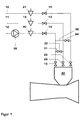
- FIG. 1 shows an example of a preferred embodiment of the invention a gas turbine equipped with a single burner.
- the one in the combustion chamber 40 built-in single burner is in the embodiment to the fuel lines 10 and 11, and the water supply line 12 connected.
- the leads are equipped with quick-closing valves 19, 20 and 21.
- the control valves 13, 15 and 16 regulate the water or fuel quantities, the valve 14 the pressure in the water line 12, which with the lockable test lines 31,32 the fuel lines 10, 11 is connected.
- the shut-off 34 closed and the shut-off device 25 must be open. It is now possible during operation of the gas turbine, the fuel line 11 is sealed check.
- the quick-closing valve 19 and the shut-off device 26 closed.
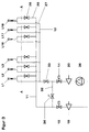
- FIG. 2 A particularly simple example of the embodiment of the embodiment of the invention is shown in Fig. 2.
- the fuel line 11 to be tested and the Water line 12 are via branch lines 27 and 28 with 18 in this example Single burners L1 to L18 connected.
- the branches of the spur lines 27.28 from the Manifolds 11 and 12 can also be arranged individual switching valves, which at the leak test described below must be open.
- the in this case, connecting the burner to the water supply is mandatory.
- the second fuel line is not for reasons of clarity drawn.
- the line marked A-A schematically represents the Separation between burner and supply line. Inside the burner or in In a burner system are the fuel line to be tested and the Water pipe connected by check valves 24.
- Fig. 3 is a modification of the embodiment shown in Fig. 2 shown. New are those that are mounted directly on the burners or in the Burner integrated shut-off devices 26, the test line 32, and the Shut-off devices 33 and 34.
- the shut-off devices 26 and 33 closed. The water fills over the test line 32 and that open shut-off valve 34 with the fuel line 11 and the branch lines 28 Water at a pressure equal to the maximum operating pressure of the Fuel line 11 corresponds. After closing the shut-off device 34 again the pressure drop in the lines can be evaluated.
Abstract
Description
Die vorliegende Erfindung betrifft ein Verfahren zum Prüfen der Dichtigkeit von Brennstoffleitungen von in Wärmeerzeugern eingebauten Mehrbrennstoff-Brennern mit getrennten Zuleitungen für jeden eingesetzten Brennstoff, wobei in bestimmten Betriebszuständen mindestens eine Brennstoffleitung nicht benutzt wird, während der Wärmeerzeuger betrieben wird.The present invention relates to a method for testing the tightness of Fuel lines from multi-fuel burners installed in heat generators with separate feed lines for each fuel used, whereby in certain operating conditions at least one fuel line is not is used while the heat generator is in operation.
Die hohen Investitionskosten moderner feuerungstechnischer Anlagen fordern zu deren wirtschaftlichem Betrieb eine hohe Verfügbarkeit und den Einsatz des jeweils wirtschaftlichsten Brennstoffes. Die Brennstoffauswahl wird weiterhin durch die Forderung nach einem geringen Schadstoffausstoss und durch betriebstechnische Gründe massgeblich beeinflusst. Beim Einsatz von Gasturbinen zur Stromerzeugung wird daher in hohem Ausmasse auf in Pipelines herangeführtes Erdgas zurückgegriffen. The high investment costs of modern firing systems demand high availability and the use of the most economical fuel. The fuel selection will continue through the demand for low pollutant emissions and through operational reasons significantly influenced. When using Gas turbines for electricity generation are therefore used to a large extent in Pipelines brought in natural gas.
Gerade in aufstrebenden Schwellenländern mit einer nicht ausreichend stabilen Infrastruktur besteht aber ein nicht zu unterschätzendes Risiko, dass eine hinreichende Gasversorgung nicht immer gewährleistet werden kann, der Ausfall eines in Grundlast betriebenen Kraftwerksblockes jedoch zu erheblichen Problemen in der Stromversorgung einer Region führt. Da nun andererseits Gas sehr schlecht zu speichern ist, werden solche Kraftwerke, aber auch andere feuerungstechnische Anlagen, gerne als sogenannte Dual Fuel Anlagen ausgeführt. Für einige Tage kann dann leicht zu speicherndes Öl als Backup Fuel eingesetzt werden.Especially in emerging economies with an insufficiently stable infrastructure, there is a risk that should not be underestimated that an adequate gas supply cannot always be guaranteed, but the failure of a power plant unit operated in base load leads to considerable problems in the power supply of a region. On the other hand, since gas is very difficult to store, such power plants, but also other combustion engineering systems, are often designed as so-called dual fuel systems. Oil that is easy to store can then be used as backup fuel for a few days.
Eine solche Bauweise bedingt selbstverständlich mehrere Brennstoff-Versorgungsleitungen, die aus Gründen der einfachen Montage und Wartung im allgemeinen mit lösbaren Verbindungen ausgerüstet sind. Diese bergen das permanente Risiko von Brennstoffleckagen.Such a construction naturally requires several fuel supply lines, for reasons of easy assembly and maintenance are generally equipped with detachable connections. These hide that permanent risk of fuel leakage.
Die unkontrollierbaren Gefahren einer unbemerkten Brennstoffleckage sind nun ohne weiteres nachzuvollziehen: Neben den wirtschaftlichen Auswirkungen eines Anlagenausfalls sind auch Menschenleben akut gefährdet. Dies sei nochmals am Beispiel einer Kraftwerks-Gasturbine in der oben erwähnten Dual-Fual Bauweise geschildert. Aus wirtschaftlichen Gründen werden diese meist nur einen Bruchteil ihrer Betriebszeit mit dem Zweitbrennstoff, in diesem Falle Öl, betrieben. Während der anderen Zeit sind die Verbindungen der Ölzuleitungen ohne Belastung durch den Brennstoffdruck thermischem Stress und den Schwingungen der Maschine ausgesetzt, was selbstverständlich ein Lösen der Schraubverbindungen fördert. Dadurch wird einerseits das quantitative Risiko einer Ölleckage gross. Auf der anderen Seite ist eine Leckage des Flüssigbrennstoffs ungleich kritischer als eine Gasleckage: Letztere kann durch Gasschnüffler frühzeitig erkannt werden. Weiterhin bedarf Gas zu seiner Entzündung eines recht eng definierten Konzentrationsbereichs und einer Initialzündung. Öl hingegen kann sich auf der heissen Oberfläche einer Gasturbinen-Brennkammer spontan entzünden. Auf jeden Fall aber bedingen Reinigungsarbeiten nach einer Ölleckage einen mehrtägigen Anlagenstillstand. The uncontrollable dangers of an unnoticed fuel leak are now easy to understand: In addition to the economic impact A plant failure is also an acute risk to human life. This is again using the example of a power plant gas turbine in the above Dual-fual construction described. For economic reasons, these are usually only a fraction of their operating time with the second fuel, in this Trap oil operated. During the other time the connections are the Oil supply lines without stress from the fuel pressure thermal stress and exposed to the vibrations of the machine, which is a matter of course Loosening the screw connections promotes. On the one hand, this means that quantitative risk of oil leakage large. On the other hand, there is one Leakage of the liquid fuel is much more critical than a gas leak: The latter can be recognized early by gas sniffers. Still needs Gas for igniting a rather narrowly defined concentration range and an initial spark. Oil, however, can be on the hot surface ignite spontaneously in a gas turbine combustion chamber. In any case cleaning work after an oil leak requires a multi-day Plant shutdown.
Eine Übertragung des oben dargestellten Szenarios auf eine Vielzahl feuerungstechnischer Anwendungen ist trivial. Wünschenswert ist daher, im Interesse der Betriebssicherheit und der Verfügbarkeit feuerungstechnischer Anlagen die Möglichkeit zu schaffen, während des Betriebs einer solchen Anlage die Dichtheit der Brennstoffleitungen zu prüfen, denn aus wirtschaftlichen Gründen ist es kaum möglich, beispielsweise die oben erwähnte in Grundlast mit Erdgas betriebene Gasturbine regelmässig zur Leckageprüfung der Ölzuleitungen stillzulegen.A transfer of the scenario outlined above to a large number firing applications is trivial. It is therefore desirable in Interest in operational safety and the availability of combustion technology Facilities to create the possibility of operating such System to check the tightness of the fuel lines, because from it is hardly possible for economic reasons, for example the above mentioned gas turbine operated regularly in base load with natural gas Decommission the leakage test of the oil supply lines.
Ein Verfahren zur Leckageprüfung von Brennstoffleitungen während des Betriebs eines Wärmeerzeugers ist Gegenstand der vorliegenden Erfindung.A procedure for leakage testing of fuel lines during the Operation of a heat generator is the subject of the present invention.
Aufgabe der Erfindung ist, eine Möglichkeit zu schaffen, die Dichtheit von Brennstoffleitungen während des Betriebes des Brenners oder der Brenner zu prüfen. Eine Randbedingung der Erfindung ist, den apparativen Aufwand gering zu halten, um es der Antragstellerin zu ermöglichen, auch vorhandene Anlagen schnell und unproblematisch nachzurüsten. Zusätzlich muss das Verfahren einfach sein, um ohne wesentliche Betriebseinschränkungen durch das Bedienungspersonal einer Anlage ausgeführt werden zu können.The object of the invention is to provide a way to ensure the tightness of Fuel lines during burner or burner operation too check. A boundary condition of the invention is the expenditure on equipment to be kept low in order to enable the applicant, even existing ones Retrofitting systems quickly and easily. In addition that Procedures to be simple to go through without significant operational restrictions to be able to run the operating personnel of a system.
Die Aufgabe wird erfindungsgemäss dadurch gelöst, dass bei einem Mehrstoffbrenner Zuleitungen für gerade nicht benutzte Brennstoffe geprüft werden, während der Brenner mit anderen Brennstoffen betrieben wird. Die Prüfung wird mit einer nicht brennbaren Flüssigkeit durchgeführt, die unter Druck in die Leitung eingebracht wird. The object is achieved in that one Multi-fuel burner supply lines for currently unused fuels checked be operated while the burner is operated with other fuels. The Test is carried out with a non-flammable liquid that is under Pressure is introduced into the line.
Dies ermöglicht, die Dichthheitsprüfung gefahrlos während des Betriebs der Anlage, und damit ohne Beeinträchtigung des Betriebs und damit verbundener negativer wirtschaftlicher Folgen in regelmässigen Intervallen, durchzuführen. Eine eventuelle Leckage kann durch Inaugenscheinnahme der Fügestellen der Brennstoffleitung am Austritt des Hilfsmediums erkannt werden. Bei entsprechender Ausführung kann eine Leckage qualitativ auch durch Messung des Druckabfalls im System automatisch erkannt werden, wie unten beschrieben.This enables the tightness test to be carried out safely during the operation of the Plant, and thus without affecting the operation and related negative economic consequences at regular intervals. A possible leakage can be seen by inspecting the joints of the Fuel line can be recognized at the outlet of the auxiliary medium. At A leakage can also be carried out qualitatively by measurement of the pressure drop in the system are automatically recognized as below described.
In einer bevorzugten Ausführungsform des Verfahrens wird Wasser als Hilfsmedium zur Dichtheitsprüfung eingesetzt. Gerade bei einer regelmässigen Routineprüfung zeigt sich Wasser als billig, umweltfreundlich und leicht zu handhaben.In a preferred embodiment of the method, water is used as Auxiliary medium used for leak testing. Especially with a regular Routine testing shows water to be cheap, environmentally friendly and easy to use handle.
In dieser Ausführungsvariante kann ein möglicherweise vorhandenes System, das Wasser beispielsweise zur Stickoxidreduktion oder zur Leistungserhöhung einer Gasturbine in den Wärmeerzeuger eindüst, herangezogen werden, um das zur Dichtheitsprüfung benötigte Medium unter Druck bereitzustellen. Ebenso kann unter Druck stehendes Wasser an geeigneter Stelle aus einem von der Feuerung beheizten Wasser-Dampf Kreislauf benutzt werden, beispielsweise durch eine Anzapfung der Kesselspeisepumpe.In this embodiment variant, a possibly existing system, the water, for example, to reduce nitrogen oxide or increase performance a gas turbine into the heat generator, be used to to provide the medium required for the leak test under pressure. Likewise, water under pressure can be extracted from a suitable location water-steam circuit heated by the furnace can be used, for example by tapping the boiler feed pump.
Eine apparativ besonders einfache Ausführung des erfindungsgemässen Verfahrens ergibt sich, wenn die Feuerung mit dem von der Antragstellerin eingesetzten emissionsarmen Mehrbrennersystem für flüssige und gasförmige Brennstoffe ausgestattet ist. Diese sind ohnehin mit einer Wasserzuführung zur Stickoxidreduzierung im Betrieb mit Flüssigbrennstoff ausgestattet. Dabei sind die Zuführungen von Flüssigbrennstoff und Wasser in der Brennerlanze verbunden, in der Weise, dass ein Rückschlagventil den Eintritt von Brennstoff in die Wasserzuführung verhindert. Wird nun im Gasbetrieb bei hoher Last Wasser in die Brennkammer eingedüst, so wird sich über diese Verbindung in der Leitung für den Flüssigbrennstoff Druck aufbauen bis zum nächsten stromauf liegenden geschlossenen Absperrorgan. Eine Dichtheitsprüfung des komplexen Brennstoffsystems kann dann durch Inaugenscheinnahme der Fügestellen vorgenommen werden. Eine automatische Detektion über den Druckabfall, wie unten beschrieben, kann nicht vorgenommen werden, da das System in diesem Fall zum Brennraum hin offen ist.A particularly simple embodiment of the inventive The procedure results when the firing is carried out with that of the applicant Low-emission multi-burner system used for liquid and gaseous Fuel is equipped. These are with a water supply anyway Nitrogen oxide reduction in operation equipped with liquid fuel. Are there the supply of liquid fuel and water in the burner lance connected, in such a way that a check valve prevents the entry of fuel prevented in the water supply. Will now be in gas operation at high load Water is injected into the combustion chamber, so this connection is in build up pressure for the liquid fuel line until the next closed shut-off valve upstream. A leak test of the complex fuel system can then be inspected by Joints are made. Automatic detection via the Pressure drop as described below cannot be made because the System in this case is open to the combustion chamber.
Ist die oben beschriebene Verbindung zwischen einer Wassereindüsung und der Brennstoffzufuhr nicht gegeben, so kann das Wasser auch über eine externe Prüfleitung in das Brennstoff-Versorgungssystem eingebracht werden.Is the connection between a water injection and the fuel supply is not given, the water can also have a external test lead can be inserted into the fuel supply system.
Werden in einem Mehrbrennersystem die Brenner durch Einzelschaltventile angesteuert, und ist die externe Prüfleitung stromauf derselben angebracht, so kann die Brennstoffleitung bis zu den Einzelschaltventilen automatisiert überprüft werden, indem bei geschlossenen Einzelschaltventilen Hilfsmedium bis zum erwarteten Betriebsdruck der Brennstoffleitungen in dieselben gepresst und danach die Zufuhr des Hilfsmediums geschlossen wird. Der Druckabfall in der Brennstoffleitung darf dabei einen anlagenspezifisch vorzugebenden Wert nicht überschreiten; ansonsten liegt eine Leckage vor, deren Ort durch Sichtprüfung zu bestimmen ist. Die Messung und Auswertung des Druckabfalls kann dabei automatisiert erfolgen.In a multi-burner system, the burners are switched by individual switching valves controlled, and the external test line is attached upstream thereof, so the fuel line can be automated down to the individual switching valves can be checked by using auxiliary medium when the individual switching valves are closed pressed into the fuel lines up to the expected operating pressure and then the supply of the auxiliary medium is closed. The pressure drop in the fuel line may have a system-specific value do not exceed; otherwise there is a leak, the location of which Visual inspection is to be determined. The measurement and evaluation of the pressure drop can be done automatically.
Weiterhin besteht auch die Möglichkeit, speziell für die Dichtheitsprüfung Absperrorgane direkt am Eintritt der Brennstoffleitung in den oder in die Brenner einzubringen. Werden die Absperrorgane geschlossen, so kann ebenfalls Hilfsmedium unter Druck in die Brennstoffleitung eingebracht, und der Druckabfall gemessen und ausgewertet werden.Furthermore, there is also the possibility, especially for the leak test Shut-off devices directly at the entry of the fuel line into or into the Bring in the burner. If the shut-off devices are closed, then also introduced auxiliary medium under pressure in the fuel line, and the Pressure drop can be measured and evaluated.
Schliesslich besteht im Falle der beiden letztgenannten Verfahrensvarianten die Möglichkeit, bei automatisierter Auswertung des Tests und negativem Ergebnis der Dichtheitsprüfung direkt die Brennstoffzufuhr in die betroffene Leitung über ein Schnellschlussventil oder einen Trip der Brennstoffpumpe zu blockieren. Finally, in the case of the latter two process variants the possibility with automated evaluation of the test and negative Result of the leak test directly the fuel supply into the affected Line via a quick-closing valve or a trip to the fuel pump To block.
Nachfolgend ist anhand der Zeichnung für unterschiedliche Brennstoffsysteme je ein Ausführungsbeispiel der Erfindung näher erläutert. In der Zeichnung sind jeweils nur die für das Verständnis der Erfindung unmittelbar notwendigen Komponenten dargestellt. Teilweise ist im Sinne einer besseren Übersichtlichkeit der Zeichnung nur eine Brennstoffleitung dargestellt, da der notwendige Anschluss einer zweiten Brennstoffleitung für den Fachmann ohne weiteres nachvollziehbar ist.The following is based on the drawing for different fuel systems one embodiment of the invention each explained in more detail. In the drawing are only those that are directly necessary for understanding the invention Components shown. Partly is in the sense of a better one Clarity of the drawing only shows a fuel line, because of necessary connection of a second fuel line for the specialist without further is understandable.
Ebenso ist in allen Figuren eine Wassereinspritzung in den Brenner dargestellt. Wo dies nicht explizit erwähnt ist, ist diese für die Ausführung der Erfindung nicht zwingend erforderlich.Water injection into the burner is also shown in all figures. Where this is not explicitly mentioned, this is for the implementation of the invention not mandatory.
Fig. 1 zeigt beispielhaft eine bevorzugte Ausführungsvariante der Erfindung an
einer mit Einzelbrenner ausgestatteten Gasturbine. Der in der Brennkammer 40
eingebaute Einzelbrenner ist im Ausführungsbeispiel an die Brennstoffleitungen
10 und 11, sowie die Wasserzuleitung 12 angeschlossen. Die Zuleitungen sind
mit Schnellschlussventilen 19, 20 und 21 ausgestattet. Die Regelventile 13, 15
und 16 regeln die Wasser- bzw. Brennstoffmengen, das Ventil 14 den Druck in
der Wasserleitung 12, welche über die absperrbaren Prüfleitungen 31,32 mit
den Brennstoffleitungen 10, 11 verbunden ist. Wird nun mit dem über die
Leitung 10 zugeführten Brennstoff gefeuert, muss das Absperrorgan 34
geschlossen und das Absperrorgan 25 geöffnet sein. Es ist nun möglich,
während des Betriebes der Gasturbine die Brennstoffleitung 11 auf Dichtheit zu
prüfen. Dazu werden das Schnellschlussventil 19 und das Absperrorgan 26
geschlossen. Über das Druckregelventil 14 wird in der Leitung 12 der in der
Brennstoffleitung 11 zu erwartende Betriebsdruck eingestellt. Durch Öffnen der
Absperrorgans 33 wird die Brennstoffleitung 11 im Bereich zwischen
Schnellschlussventil 19 und Absperrorgan 26 mit Wasser gefüllt, das unter
eben diesem Druck steht. Die Brennstoffleitung 11 kann nun durch
Inaugenscheinnahme auf eventuelle Leckagen geprüft werden, oder es kann
nach Schliessen des Absperrorgans 33 der Druckabfall in der Brennstoffleitung
11 gemessen werden. Überschreitet dieser einen systemspezifischen
Grenzwert, deutet dies auf eine Leckage hin, worauf die Brennstoffleitung 11
auf die Stelle des Wasseraustritts inspiziert werden kann. Weiterhin wird bis zur
Behebung des Fehlers das Schnellschlussventil 19 in geschlossener Stellung
blockiert. Die Dichtheitsprüfung der Leitung 10 erfolgt analog, und ist für den
Fachmann leicht nachzuvollziehen.1 shows an example of a preferred embodiment of the invention
a gas turbine equipped with a single burner. The one in the
Ein apparativ besonders einfaches Beispiel für die Ausführung der Erfindung ist
in Fig. 2 dargestellt. Die zu prüfende Brennstoffleitung 11 und die
Wasserleitung 12 sind über Stichleitungen 27 und 28 mit in diesem Beispiel 18
Einzelbrennern L1 bis L18 verbunden. Je nach spezifischer Auslegung des
Systems können an den Abzweigungen der Stichleitungen 27,28 von den
Sammelleitungen 11 und 12 auch Einzelschaltventile angeordnet sein, die bei
der unten beschriebenen Dichtheitsprüfung geöffnet sein müssen. Der
Anschluss der Brenner an die Wasserversorgung ist in diesem Fall zwingend,
die zweite Brennstoffleitung aus Gründen der Übersichtlichkeit nicht
eingezeichnet. Die mit A-A gekennzeichnete Linie stellt schematisch die
Trennung zwischen Brenner und Zuleitung dar. Innerhalb der Brenner oder in
einem Brennersystem sind die zu prüfende Brennstoffleitung und die
Wasserleitung durch Rückschlagventile 24 verbunden. Dies ist bei den von der
Antragstellerin verwendeten Vormischbrennern am für Flüssigbrennstoff
verwendeten Leitungskanal der Fall, dergestallt, dass kein Brennstoff in die
Wasserzufuhr gelangen kann. Während der Durchführung der
Dichtheitsprüfung werden die Brenner mit einem über die nicht eingezeichnete
Brennstoffleitung zugeführten Brennstoff, beispielsweise Erdgas, vorzugsweise
auf hoher Last betrieben. Das Schnellschlussventil 19 ist in diesem Fall
geschlossen. Zur Dichtheitsprüfung wird das Schnellschlussventil 20 geöffnet.
Die Wasserpumpe 36 liefert Wasser unter hohem Druck.Über das Regelventil
14 wird nun die eingespritzte Wassermenge so lange gesteigert, bis der Druck
in der Wasserleitung 12 dem in der Brennstoffleitung 11 zu erwartenden
Betriebsdruck entspricht. Dieses Wasser strömt unter dem selben Druck in
über die Rückschlagventile 24 in die Brennstoffleitung 11 ein. Die Dichtheit der
Fügestellen in der Brennstoffleitung 11 und den Stichleitungen 28 kann durch
eine Inspektion derselben verifiziert werden.A particularly simple example of the embodiment of the embodiment of the invention is
shown in Fig. 2. The
Auffallend an dieser Ausführung ist der geringe erforderliche apparative Aufwand. Das erfindungsgemässe Verfahren kann an bestehenden Anlagen der Anmelderin ohne Umbauten des Leitungssystems ausgeführt werden. Jedoch ist eine Auswertung des Druckabfalls im Leitungssystem nicht möglich, da das System zum Brennraum hin offen ist.What is striking about this version is the small amount of equipment required Expenditure. The method according to the invention can be used on existing systems by the applicant without any modifications to the piping system. However, an evaluation of the pressure drop in the pipe system is not possible because the system is open to the combustion chamber.
In Fig. 3 ist eine Abwandlung des in Fig. 2 dargestellten Ausführungsbeispiels
dargestellt. Neu sind die unmittelbar an den Brennern montierten oder in die
Brenner integrierten Absperrorgane 26, die Prüfleitung 32, sowie die
Absperrorgane 33 und 34. In Abwandlung des oben beschriebenen Verfahrens
werden zur Dichtheitsprüfung während des Betriebs mit einem Brennstoff, der
über eine nicht dargestellte Brennstoffleitung zugeführt wird, die Absperrorgane
26 und 33 geschlossen. Das Wasser füllt über die Prüfleitung 32 und das
offene Absperrorgan 34 die Brennstoffleitung 11 und die Stichleitungen 28 mit
Wasser bei einem Druck, der dem maximalen Betriebsdruck der
Brennstoffleitung 11 entspricht. Nach Schliessen des Absperrorgans 34 kann
wiederum der Druckabfall in den Leitungen ausgewertet werden. In Fig. 3 is a modification of the embodiment shown in Fig. 2
shown. New are those that are mounted directly on the burners or in the
Burner integrated shut-off
- 1010th
- BrennstoffleitungFuel line
- 1111
- BrennstoffleitungFuel line
- 1212th
- Zuleitung für nicht brennbares inkompressibles MediumSupply line for non-flammable incompressible medium
- 1313
- RegelventilControl valve
- 1414
- RegelventilControl valve
- 1515
- RegelventilControl valve
- 1616
- RegelventilControl valve
- 1919th
- SchnellschlussventilQuick-closing valve
- 2020th
- SchnellschlussventilQuick-closing valve
- 2121
- SchnellschlussventilQuick-closing valve
- 2424th
- Rückschlagventilcheck valve
- 2525th
- AbsperrorganShut-off device
- 2626
- AbsperrorganShut-off device
- 2727
- WasserleitungWater pipe
- 2828
- BrennstoffleitungFuel line
- 3131
- PrüfleitungTest management
- 3232
- PrüfleitungTest management
- 3333
- AbsperrorganShut-off device
- 3434
- AbsperrorganShut-off device
- 3636
- Pumpe für nicht brennbares inkompressibles MediumPump for non-flammable incompressible medium
- 4040
- BrennraumCombustion chamber
- L1 ... L18L1 ... L18
- Brennerburner
- A-AA-A
- Trennung zwischen Brennstoffzuleitungen und Brennern oder BrennersystemSeparation between fuel supply lines and burners or Burner system
Claims (10)
Priority Applications (1)
| Application Number | Priority Date | Filing Date | Title |
|---|---|---|---|
| EP98810689A EP0973021A1 (en) | 1998-07-17 | 1998-07-17 | Procedure for testing of fuel passages |
Applications Claiming Priority (1)
| Application Number | Priority Date | Filing Date | Title |
|---|---|---|---|
| EP98810689A EP0973021A1 (en) | 1998-07-17 | 1998-07-17 | Procedure for testing of fuel passages |
Publications (1)
| Publication Number | Publication Date |
|---|---|
| EP0973021A1 true EP0973021A1 (en) | 2000-01-19 |
Family
ID=8236201
Family Applications (1)
| Application Number | Title | Priority Date | Filing Date |
|---|---|---|---|
| EP98810689A Withdrawn EP0973021A1 (en) | 1998-07-17 | 1998-07-17 | Procedure for testing of fuel passages |
Country Status (1)
| Country | Link |
|---|---|
| EP (1) | EP0973021A1 (en) |
Cited By (2)
| Publication number | Priority date | Publication date | Assignee | Title |
|---|---|---|---|---|
| ITMI20101372A1 (en) * | 2010-07-26 | 2012-01-27 | Ansaldo Energia Spa | METHOD AND EQUIPMENT TO DETECT LIQUID FUEL LEAKS IN A COMBUSTION GROUP OF A GAS TURBINE SYSTEM |
| DE202012006442U1 (en) | 2011-11-24 | 2012-09-17 | Minimax Gmbh & Co. Kg | Device for leak testing of pipelines |
Citations (5)
| Publication number | Priority date | Publication date | Assignee | Title |
|---|---|---|---|---|
| DE2706541A1 (en) * | 1977-02-14 | 1978-08-17 | Mannesmann Ag | MONITORING DEVICE FOR THE SUPPLY LINE OF AN OIL-SUPPLIED UNIT |
| US4197733A (en) * | 1979-03-28 | 1980-04-15 | Holland Richard W | Pressure test apparatus |
| US5307620A (en) * | 1991-04-09 | 1994-05-03 | Kawasaki Jukogyo Kabushiki Kaisha | Fuel gas burning control method |
| DE4335412A1 (en) * | 1993-10-18 | 1995-04-20 | Abb Management Ag | Method and device for fuel distribution in annular combustion chambers of gas turbine plants |
| DE19513158A1 (en) * | 1995-04-07 | 1996-10-10 | Bosch Gmbh Robert | Device for detecting a leak in a fuel supply system |
-
1998
- 1998-07-17 EP EP98810689A patent/EP0973021A1/en not_active Withdrawn
Patent Citations (5)
| Publication number | Priority date | Publication date | Assignee | Title |
|---|---|---|---|---|
| DE2706541A1 (en) * | 1977-02-14 | 1978-08-17 | Mannesmann Ag | MONITORING DEVICE FOR THE SUPPLY LINE OF AN OIL-SUPPLIED UNIT |
| US4197733A (en) * | 1979-03-28 | 1980-04-15 | Holland Richard W | Pressure test apparatus |
| US5307620A (en) * | 1991-04-09 | 1994-05-03 | Kawasaki Jukogyo Kabushiki Kaisha | Fuel gas burning control method |
| DE4335412A1 (en) * | 1993-10-18 | 1995-04-20 | Abb Management Ag | Method and device for fuel distribution in annular combustion chambers of gas turbine plants |
| DE19513158A1 (en) * | 1995-04-07 | 1996-10-10 | Bosch Gmbh Robert | Device for detecting a leak in a fuel supply system |
Cited By (3)
| Publication number | Priority date | Publication date | Assignee | Title |
|---|---|---|---|---|
| ITMI20101372A1 (en) * | 2010-07-26 | 2012-01-27 | Ansaldo Energia Spa | METHOD AND EQUIPMENT TO DETECT LIQUID FUEL LEAKS IN A COMBUSTION GROUP OF A GAS TURBINE SYSTEM |
| EP2439448A1 (en) * | 2010-07-26 | 2012-04-11 | Ansaldo Energia S.p.A. | Method and device for detecting liquid fuel leakage in a gas turbine system combustion assembly |
| DE202012006442U1 (en) | 2011-11-24 | 2012-09-17 | Minimax Gmbh & Co. Kg | Device for leak testing of pipelines |
Similar Documents
| Publication | Publication Date | Title |
|---|---|---|
| DE60124466T2 (en) | Method and device for reducing the emission of a combustion chamber | |
| EP1059488B1 (en) | Process and installation for heating a liquid medium | |
| DE112015002636T5 (en) | Method for flushing the fuel channel, flushing device for carrying out said method and gas turbine installation provided with the same device | |
| DE112009002724B4 (en) | System and method for washing and flushing the liquid fuel line of a turbine with water | |
| DE4339094A1 (en) | Damping of thermal-acoustic vibrations resulting from combustion of fuel | |
| DE60012684T2 (en) | Multipurpose manifold for water injection of a gas turbine and its operation | |
| DE102018123515A1 (en) | Leakage detection system and method for a gas turbine engine | |
| DE102015106676A1 (en) | Simplified water injection system for a combined cycle power plant | |
| DE102022210265A1 (en) | gas turbine plant | |
| DE4211681C2 (en) | Method for controlling the burning of a fuel gas | |
| EP0184836A2 (en) | Method of and device for leak testing of two check valves in a gas-operated pipe | |
| EP0915240B1 (en) | Leakage testing of gas turbine fuel manifolds | |
| EP0663561B1 (en) | Steam generator | |
| EP0973021A1 (en) | Procedure for testing of fuel passages | |
| DE19633674C2 (en) | In-line gas preheating | |
| DE102013211376B4 (en) | Method and device for controlling the injection of water into the flue gas duct of a gas and steam turbine plant | |
| DE102020116222B4 (en) | Gas supply system for a gas engine or dual fuel engine and method of operating the same | |
| DE2728826C2 (en) | Device for limiting the amount of fuel gas supplied to the gas flare system in the case of a coal pressure regulator provided with a downstream gas-steam turbine power plant. | |
| DE4335412B4 (en) | Process and device for fuel distribution for annular combustion chambers of gas turbine plants | |
| DE102011118411A1 (en) | Combustion chamber and method for supplying fuel to a combustion chamber | |
| EP2535543B1 (en) | Method for operating a fuel supply for a heat engine | |
| WO1996028689A1 (en) | Method and device for monitoring the feed-water supply to a steamgenerator | |
| DE10196104B4 (en) | Graphite body impregnated with a light metal alloy, process for its preparation and its use | |
| WO2016000994A1 (en) | Method and device for purging and/or sealing at least one burner of a gas turbine installation | |
| DE102014212824A1 (en) | Method and device for flushing and / or blocking at least one burner of a gas turbine plant |
Legal Events
| Date | Code | Title | Description |
|---|---|---|---|
| PUAI | Public reference made under article 153(3) epc to a published international application that has entered the european phase |
Free format text: ORIGINAL CODE: 0009012 |
|
| AK | Designated contracting states |
Kind code of ref document: A1 Designated state(s): AT BE CH CY DE DK ES FI FR GB GR IE IT LI LU MC NL PT SE |
|
| AX | Request for extension of the european patent |
Free format text: AL;LT;LV;MK;RO;SI |
|
| AKX | Designation fees paid | ||
| STAA | Information on the status of an ep patent application or granted ep patent |
Free format text: STATUS: THE APPLICATION IS DEEMED TO BE WITHDRAWN |
|
| 18D | Application deemed to be withdrawn |
Effective date: 20000720 |