EP2439367A2 - Schaltleiste - Google Patents
Schaltleiste Download PDFInfo
- Publication number
- EP2439367A2 EP2439367A2 EP11183864A EP11183864A EP2439367A2 EP 2439367 A2 EP2439367 A2 EP 2439367A2 EP 11183864 A EP11183864 A EP 11183864A EP 11183864 A EP11183864 A EP 11183864A EP 2439367 A2 EP2439367 A2 EP 2439367A2
- Authority
- EP
- European Patent Office
- Prior art keywords
- flange structure
- sensing edge
- vertical groove
- plug
- assembled configuration
- Prior art date
- Legal status (The legal status is an assumption and is not a legal conclusion. Google has not performed a legal analysis and makes no representation as to the accuracy of the status listed.)
- Granted
Links
- 239000011800 void material Substances 0.000 claims description 12
- 239000000463 material Substances 0.000 claims description 4
- 241001465754 Metazoa Species 0.000 description 5
- 238000010276 construction Methods 0.000 description 4
- 239000007787 solid Substances 0.000 description 4
- 241000283984 Rodentia Species 0.000 description 2
- 239000000853 adhesive Substances 0.000 description 2
- 230000001070 adhesive effect Effects 0.000 description 2
- 230000000903 blocking effect Effects 0.000 description 2
- 238000003780 insertion Methods 0.000 description 2
- 230000037431 insertion Effects 0.000 description 2
- 239000004821 Contact adhesive Substances 0.000 description 1
- 239000004820 Pressure-sensitive adhesive Substances 0.000 description 1
- 230000005540 biological transmission Effects 0.000 description 1
- 230000008676 import Effects 0.000 description 1
- 238000009434 installation Methods 0.000 description 1
- 238000012986 modification Methods 0.000 description 1
- 230000004048 modification Effects 0.000 description 1
- 239000000126 substance Substances 0.000 description 1
Images
Classifications
-
- E—FIXED CONSTRUCTIONS
- E05—LOCKS; KEYS; WINDOW OR DOOR FITTINGS; SAFES
- E05F—DEVICES FOR MOVING WINGS INTO OPEN OR CLOSED POSITION; CHECKS FOR WINGS; WING FITTINGS NOT OTHERWISE PROVIDED FOR, CONCERNED WITH THE FUNCTIONING OF THE WING
- E05F15/00—Power-operated mechanisms for wings
- E05F15/40—Safety devices, e.g. detection of obstructions or end positions
- E05F15/42—Detection using safety edges
- E05F15/48—Detection using safety edges by transmission of mechanical forces, e.g. rigid or movable members
-
- E—FIXED CONSTRUCTIONS
- E05—LOCKS; KEYS; WINDOW OR DOOR FITTINGS; SAFES
- E05F—DEVICES FOR MOVING WINGS INTO OPEN OR CLOSED POSITION; CHECKS FOR WINGS; WING FITTINGS NOT OTHERWISE PROVIDED FOR, CONCERNED WITH THE FUNCTIONING OF THE WING
- E05F15/00—Power-operated mechanisms for wings
- E05F15/40—Safety devices, e.g. detection of obstructions or end positions
- E05F15/42—Detection using safety edges
- E05F15/44—Detection using safety edges responsive to changes in electrical conductivity
-
- E—FIXED CONSTRUCTIONS
- E05—LOCKS; KEYS; WINDOW OR DOOR FITTINGS; SAFES
- E05Y—INDEXING SCHEME ASSOCIATED WITH SUBCLASSES E05D AND E05F, RELATING TO CONSTRUCTION ELEMENTS, ELECTRIC CONTROL, POWER SUPPLY, POWER SIGNAL OR TRANSMISSION, USER INTERFACES, MOUNTING OR COUPLING, DETAILS, ACCESSORIES, AUXILIARY OPERATIONS NOT OTHERWISE PROVIDED FOR, APPLICATION THEREOF
- E05Y2600/00—Mounting or coupling arrangements for elements provided for in this subclass
- E05Y2600/40—Mounting location; Visibility of the elements
-
- E—FIXED CONSTRUCTIONS
- E05—LOCKS; KEYS; WINDOW OR DOOR FITTINGS; SAFES
- E05Y—INDEXING SCHEME ASSOCIATED WITH SUBCLASSES E05D AND E05F, RELATING TO CONSTRUCTION ELEMENTS, ELECTRIC CONTROL, POWER SUPPLY, POWER SIGNAL OR TRANSMISSION, USER INTERFACES, MOUNTING OR COUPLING, DETAILS, ACCESSORIES, AUXILIARY OPERATIONS NOT OTHERWISE PROVIDED FOR, APPLICATION THEREOF
- E05Y2800/00—Details, accessories and auxiliary operations not otherwise provided for
- E05Y2800/10—Additional functions
- E05Y2800/12—Sealing
Definitions
- Preferred embodiments of the present invention relate to end flaps for use with sensing edges for automatic doors or the like.
- Sensing edges for automatic doors are generally known. A description of a sensing edge can be found, for example, in U.S. Patent No. 6,571,512 , titled “Universal Sensing Edge with Non-Melt End Closure,” and which disclosure is incorporated by reference herein in its entirety.
- Sensing edges generally include an elongated sheath configured to sense force. Upon an application of a force to the sheath, the elongated sheath actuates suitable control circuitry for controlling movement of a door.
- a force For example, an automatic door can have a sensing edge on a bottom edge. If an object is below the elongated sheath, the elongated sheath is pressured by the object when the automatic door impacts the object when closing. Such force is "sensed" by the elongated sheath, which results in a predetermined signal being sent to a mechanism which opens or closes the automatic door to cause the automatic door to stop moving to prevent damage to the object or the door.
- a space remains between the sensing edge and a wall or other structure adjacent to the automatic door.
- the space can be a source of light or a path through which rodents or other animals may enter past the edge of the automatic door.
- snow, rain, leaves or other objects may enter the structure associated with the door, even when the door is closed. Accordingly, it is desirable to design and construct a sensing edge for a door that blocks the space to impede the aforementioned lights, rodents, debris or other objects from moving through the space past the door when the door is closed.
- a preferred embodiment of the present application is directed to a sensing edge for providing a signal to a controller indicating that a forward edge of a door is obstructed during operation.
- the sensing edge includes an elongate sheath, a first end plug and a first end flap.
- the elongate sheath has a first end and a second end.
- a first cavity is located at the first end.
- the elongate sheath is mounted to the forward edge.
- the first end plug includes an inner end, an outer end, first engaging structures extending from the inner end and a first vertical groove in the outer end.
- the engaging structures are positioned within the first cavity in an assembled configuration.
- the first end flap includes a relatively flat first body and a first flange structure.
- the first flange structure is positioned in the first vertical groove in the assembled configuration to secure the first end flap to the first end plug.
- a preferred embodiment of the present invention is directed to an end assembly for a sensing edge for providing a signal to a controller indicating that a forward edge of a door is obstructed during operation.
- the end assembly includes a first end plug and a first end flap.
- the first end plug has an inner end, an outer end, first engaging structures extending from the inner end, a first vertical groove in the outer end and a horizontal groove in the outer end.
- the outer end defines an outer plane.
- the first end flap includes a first body and a first flange structure. The first body is positioned on a first side of the outer plane and the first flange structure is positioned on an opposite second side of the outer plane in an assembled configuration.
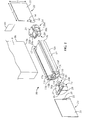
- Fig .1 is a right-side perspective, partially exploded fragmentary view of a sensing edge in accordance with a first preferred embodiment of the present application and an automatic door;
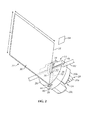
- Fig. 2 is a front perspective view of an end cap and an end flap of the sensing edge of Fig. 1 ;
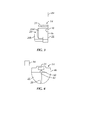
- Fig. 3 is a right-side elevational view of the end cap of Fig. 1 ;
- Fig. 4 is a front elevational view of the end cap of Fig. 1 ;
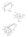
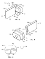
- Fig. 5 is a rear perspective view of an end flap of a sensing edge in accordance with a second preferred embodiment of the present application
- Fig. 6 is a front perspective view of an end cap of a sensing edge in accordance with the second preferred embodiment of the present application.
- Fig. 7 is a rear perspective view of the end flap and end cap of Figs. 5 and 6 in an assembled configuration
- Fig. 8 is a front perspective view of an end flap and an end cap in accordance with a third preferred embodiment of the present application in an assembled configuration
- Fig. 9 is a rear perspective, partially exploded view of the end cap and end flap of Fig. 8 ;
- Fig. 10 is a front elevational view of the end cap of Fig. 8 .
- a sensing edge 10 in accordance with a first preferred embodiment of the present application includes an elongated sheath 12, a first end plug 14, and a first end flap 22.
- the sensing edge 10 is preferably mounted to a door, gate or other structure 9 that opens and/or closes upon actuation by a user.
- the door 9 is typically driven to open or close by a driving motor (not shown) upon remote actuation by the user.
- the door 9 may be comprised of a garage door 9, a gate 9 or nearly any door or structure that opens and/or closes based upon actuation by the user.
- the sensing edge 10 is preferably mounted to the door 9 to provide a signal to a controller 100 indicating that an edge, preferably a forward edge 9a of the door 9 is obstructed during operation.
- the sensing edge 10 preferably prevents the door 9 from damaging an object that obstructs the opening and/or closing path of the door 9 by sensing the object when the sensing edge 10 comes into contact with the object during use.
- the sensing edge 10 is preferably mounted to an edge 9a of the door 9 that may come into contact with an object during opening and/or closing.
- the sensing edge 10 may be mounted to the bottom or forward edge 9a of a garage door 9 such that the sensing edge 10 comes into contact with objects or people that may obstruct the opening and/or closing of the door 9, as would be understood by one having ordinary skill in the art.
- the sensing edge 10 is not limited to being mounted to the bottom or forward edge of the door 9 and may be mounted to a side edge of the door 9, particularly for a door 9 that opens or closes by travelling laterally on a track (not shown), as opposed to a traditional garage door 9 that generally opens and closes along a generally vertical path.
- the sensing edge 10 is preferably mounted to the door 9 along an edge where it may come into contact with an object during the opening and/or closing operations, which may be described as the forward edge 9a of the door 9.
- the elongated sheath 12 of the sensing edge 10 of the first preferred embodiment has a first end 16 and a second end 18.
- the first end plug 14 is positioned to engage and close the first end 16.
- engaging structures 20 on the first end plug 14 are inserted into the elongated sheath 12 at the first end 16 to frictionally engage the elongated sheath 12 and permit the first end plug 14 to close the first end 16.
- the first end flap 22 is preferably slidingly engaged with the first end plug 14.
- An adhesive or other fastening device may also be used to secure the first end plug 14 to the elongated sheath 12.
- the first end flap 22 preferably has a substantially rectangular shape, with one or more corners optionally having rounded shapes.
- the length of the elongated sheath 12 is not drawn to scale in Fig. 1 , and is of a length appropriate for attachment to the entire length of the door 9 onto which the sensing edge 10 will be attached.
- a second end plug 15 is also utilized to close the second end 18 and is positioned in similar fashion as the first end plug 14 in the mounted or assembled configuration.
- the first end 16 is configured for engagement with the first end plug 14 and is preferably configured to receive the engaging structures 20.
- the second end 18 is likewise configured for engagement with the second end plug 15 and is preferably configured to receive engaging structures of the second end plug 15 in the mounted or assembled configuration.
- the first end plug 14 and the second end plug 15 may be the same or different, depending upon the design and/or configuration of the sensing edge 10.
- the first and second ends 16, 18 can likewise be the same or different, depending upon design of the sensing edge 10.
- the first end flap 22, first end plug 14, and elongated sheath 12 are preferably constructed of a flexible material, such as rubber or the like.
- the first end flap 22, elongated sheath 12, and first end plug 14 are configured such that when the elongated sheath 12 is attached to the bottom, forward or leading edge of the automatic door 9, the first end flap 22 is positioned in a space between the first end plug 14 and a wall or other structure (not shown) adjacent to the side of the automatic door 9, in order to block light and/or animals from entering around the door 9.
- the first end flap 22 includes a first body or flat portion 30, which is preferably comprised of a thin, planar structure.
- the first end flap 22 preferably defines a plane which is substantially parallel to a plane defined by the automatic door 9 when the sensing edge 10 is attached to the automatic door 9. This way, the first end flap 22 blocks the space adjacent to the first end plug 14 to block light and animals or other objects or substances from entry.
- the automatic door 9 is substantially vertical, and the first body 30 extends substantially vertically as well.
- the first end plug 14 of the first preferred embodiment includes an inner or first end 24 which includes the first engaging structures 20, and an outer or second end 26 which is configured to engage the first end flap 22.
- the first end plug 14 includes a first vertical groove 28 in the outer end 26 designed to engage a portion of the first end flap 22 in order to attach the first end flap 22 to the first end plug 14.
- the first vertical groove 28 preferably has a T-shape, but is not so limited and may have nearly any shape that is able to engage the first end flap 22 to secure the first end flap 22 to the first end plug 14.
- the first vertical groove 28 may be comprised of a planar section of the outer end 26 upon which the first end flap 22 is adhesively bonded, staked or otherwise secured to the first end plug 14.
- the first vertical groove 28 is an elongated groove having a T-shaped cross-section.
- the first end flap 22 includes the first body 30, a first flange structure 32 and, preferably, a second flange structure 34.
- the first and second flange structures 32, 34 are located at a first edge 31 of the first end flap 22 which faces the outer end 26 of the first end plug 14 when engaged therewith.
- the first and second flange structures 32, 34 preferably define T-shapes (i.e., "T" cross-sectional shapes) along with the first body 30 and extend laterally beyond the front and back surfaces of the first body 30.
- the first flange structure 32 is preferably located on a step portion 36 of the first end flap 22.
- the vertical T-shaped groove 28 of the first end plug 14 typically extends longitudinally in a substantially vertical direction and the first end flap 22 extends in a substantially vertical direction in the assembled configuration.
- the first flange structure 32 slides into the vertical T-shaped groove 28 from below as shown in Fig. 2 . This is done by inserting a first end 38 of the first flange structure 32 into a lateral opening 40 at a lower surface of the first end plug 14 into the vertical T-shaped groove 28 and sliding the first flange structure 32 upwards into the vertical T-shaped groove 28 until the first end 38 is stopped by a wall structure 42.
- the wall structure 42 defines an end of the vertical groove 28 in the first preferred embodiment.
- the first flange structure 32 is preferably secured in the vertical T-shaped groove 28 with preferably little or no extension of a second end 44 of the first flange structure 32 outside of the vertical T-shaped groove 28. This is accomplished by configuring the first flange structure 32 to have substantially the same length as the T-shaped groove 28.
- the step portion 36 is preferably dimensioned such that the second flange structure 34 clears the wall structure 42 and faces or is in facing engagement with the outer end 26 of the first end plug 14.
- the second flange structure 34 is preferably configured and dimensioned to maintain the end flap 22 in a position substantially perpendicular to the outer end 26, by serving as support for the first end flap 22 against the outer end 26. While the first end flap 22 may be secured to the first end plug 14 by engagement between the first flange structure 32 and the vertical T-shaped groove 28, other securing systems are envisioned.
- the first flange structure 32 can have a different cross-sectional shape, such as circular, square, triangular, etc., with the vertical T-shaped groove 28 having a different cross-sectional shape to accommodate the first flange structure 32.
- the first end flap 22 may be secured to the first end plug 14 by other ways known in the art, such as by the use of adhesives, such as contact adhesives or pressure-sensitive adhesives.
- the vertical T-shaped groove 28 is positioned at a position which approximately bisects the outer end 26.
- the end plug 14 preferably includes a horizontal groove 46 formed substantially perpendicular to a direction defined by the length of the vertical T-shaped groove 28.
- the horizontal groove 46 has a C-shaped cross-section in the first preferred embodiment such that it is open along the outer end 26.
- Such a shape allows an electric wire or cable 82 ( Fig. 2 ), especially a sheathed cable, to be secured inside the circular groove 46.
- the electric wire 82 is generally cylindrical in shape and relatively flexible along its length.
- the electrical wire 82 is preferably mounted in the horizontal groove 46 by pushing the electric wire 82 laterally through the opening 48 of the horizontal groove 46 with sufficient force to elastically deform the opening 48 and/or wire 82 to permit the wire 82 to be inserted into the circular groove 46.
- the horizontal groove 46 is preferably positioned on an opposite side of the wall structure 42 as the vertical groove 28, such that the first flange structure 32 is not positioned inside the circular groove 46.
- the electrical wire 82 provides power and/or carries electrical signals to the components of the sensing edge 10 that sense impact of the elongated sheath 10 with objects in the path of travel of the door 9. Securing the electrical wire 82 in the horizontal groove 46 generally fastens the electrical wire 82 relative to the door 9 to limit damage to the electrical wire 82 during use.
- the first end plug 14 also includes a passage 50 ( Fig. 4 ), which extends into the first end plug 14 to permit the electrical wire 82 to extend into the first end plug 14.
- the electrical wire 82 can be, for example, used to connect sensors (not shown) in the elongated sheath 12 with the control mechanism (not shown) of the automatic door 9, in order to send signals to the control mechanism generated as a result of force being applied to the elongated sheath 12.
- the electrical wire 82 preferably extend from the passage 50 and is diverted to the circular groove 46 in a direction away from the passage 50.
- the passage 50 is aligned with the horizontal groove 46 to accommodate fastening of the electrical wire 82 relative to the first end plug 14.
- the elongated sheath 12 of the first preferred embodiment includes a first cavity 17 at the first end 16 and a second cavity 19 at the second end 18.
- the engaging structures 20 of the first and second end plugs 14, 15 are mounted in the first and second cavities 17, 19 respectively. Positioning of the engaging structures 20 in the first and second cavities at least partially secures the first and second end plugs 14, 15 to the elongated sheath 12.
- the first and second end plugs 14, 15, first and second cavities 17, 19 and first and second end flaps 22, 23 have substantially the same structure and configuration and are described throughout the application with the understanding that these structures are substantially the same, but are not so limited.
- the second end plug 15 includes a second vertical groove 29, similar to the first vertical groove 28 of the first end plug 14.
- the second end flap 23 preferably includes a relatively flat or planar second body 31 and a third flange structure 33.
- the third flange structure 33 is preferably positioned in the second vertical groove 29 in the assembled configuration to secure the second end flap 23 to the second end plug 15.
- the third flange structure 33 may be interference fit into the second vertical groove 29, may be clamped to the second vertical groove 29, adhesively bonded or otherwise secured in the second vertical groove 29 to secure the second end flap 23 to the second end plug 15 in the assembled configuration.
- the second end flap 23 may be removably mountable to the second end plug 15 through releasable engagement of the third flange structure 33 with the second vertical groove 29 such that alternate flaps or structures may be engaged with the second end cap 15.
- the second end flap 23 also preferably includes a fourth flange structure 35 having a T-shaped cross-section similar to the second flange structure 34 of the first end flap 22.
- the second and fourth flange structures 34, 35 are preferably in at least partial facing engagement with the outer ends 26, 27 of the first and second end plugs 14, 15, respectively, to provide support for the bodies 30, 31 and to generally maintain the orientation of the bodies 30, 31 relative to the first and second end plugs 14, 15.
- the first and second end flaps 22, 23 are not limited to inclusion of the second and fourth flange structures 34, 35 and may be configured without the second and fourth flange structures 34, 35, respectively.
- the second and fourth flange structures 34, 35 may be adhesively bonded, clamped, staked, secured or otherwise mounted to the outer ends 26, 27 to support the bodies 30, 31 or may be completely excluded from the structure of the first and second end flaps 22, 23, depending upon user preferences.
- the elongated sheath 12 is relatively hollow between the first and second ends 16, 18.
- the elongated sheath 12 is not limited to being hollow between the first and second ends 16, 18 and may be relatively solid or may have a variety of structures between the first and second ends 16, 18 depending upon design considerations of the preferred sensing edge 10.
- the elongated sheath 12 of the first preferred embodiments includes an outer wall 12a and first, second and third ribs 13a, 13b, 13c extending from the first end 16 to the second end 18.
- the outer wall 12a and first, second and third ribs 13a, 13b, 13c define first, second, third and fourth voids 11 a, 11b, 11c, 11 d at least at the first and second ends 16, 18.
- the first, second and third ribs 13a, 13b, 13c provide a stiffness to the elongated sheath 12 to retain the general shape of the sheath 12 and to transmit forces to sensors (not shown) associated with the sheath 12.
- the first, second and third ribs 13a, 13b, 13c are preferably co-molded or co-extruded with the outer wall 12a to form the sheath 12.
- the sheath 12 is not limited to inclusion of the outer wall 12a and first, second and third ribs 13a, 13b, 13c and may be otherwise constructed.
- the elongated sheath 12 may be constructed without inclusion of the first, second and third ribs 13a, 13b, 13c such that the elongated sheath 12 is hollow between the first and second ends 16, 18 and the outer wall 12a defines a single void (not shown) therein.
- the first, second and third ribs 13a, 13b, 13c are preferred to provide strength and stiffness to the elongated sheath 12 to assist in retaining the preferred shape of the sheath 12 and to transmit forces to sensors within the sheath 12 when the sheath 12 impacts an object during opening or closing of the door 9.
- the engaging structures 20 of the first and second end plugs 14, 15 are generally identical and are described as such herein. However, the engaging structures 20 of the first and second end plugs 14, 15 are not necessarily identical and may be designed and configured based upon user preferences for mounting to the first and second ends 16, 18 and/or for connecting or engaging sensors (not shown) related to the sensing edge 10.
- the first engaging structures 20 of the first preferred embodiment include a first projection 20a, a second projection 20b, a third projection 20c and a fourth projection 20d.
- the first projection 20a is positioned within the first void 11a
- the second projection 20b is positioned within the second void 11b
- the third projection 20c is positioned within the third void 11c
- the fourth projection 20d is positioned within the fourth void 11d in the assembled configuration.
- the first, second, third and fourth projections 20a, 20b, 20c, 20d are preferably sized and configured for force-fitting into the first, second, third and fourth voids 11a, 11b, 11c, 11d, respectively, in the assembled configuration.
- the first, second, third and fourth projections 20a, 20b, 20c, 20d are not limited to being force-fit into the first, second, third and fourth voids 11a, 11 b, 11c, 11d and may be otherwise sized and configured such that the first and second end plugs 14, 15 are mounted to the first and second ends 16, 18 when the projections 20a, 20b, 20c, 20d engage the voids 11a, 11b, 11c, 11d.
- the projections 20a, 20b, 20c, 20d may be maintained in the voids 11a, 11b, 11c, 11d by the force fit or may also be secondarily engaged with the elongated sheath 12 by fastening, adhesively bonding or otherwise securing the first and second end plugs 14, 16 to the first and second ends 16, 18.
- the engagement structure 20 is not limited to inclusion of the projections 20a, 20b, 20c, 20d, as described and shown in the figures and the sheath 12 is not limited to inclusion of the voids 11a, 11b, 11c, 11d as described and shown in the figures.
- the engagement structures 20 and elongated sheath 12 and may be alternatively configured for securing the first and second end plugs 14, 15 to the sheath 12, as will be partially described in more detail below in the second and third embodiments.
- the engaging structures 20 of the first and second end plugs 14, 16 also preferably include a top projection 21 that does not extend into any of the voids 11a, 11b, 11c, 11d of the elongated sheath 12 in the assembled configuration.
- the top projection 21 extends above the first void 11a to create consistent contact between the outer wall 12a and the first projection 20a.
- the first projection 20a is a conductive component that transmits signals to and from the controller 100 along with the outer wall 12a. Accordingly, consistent contact between the outer wall 12a and the first projection 20a is preferred to facilitate transmission of the signals between the first projection 20a and the outer wall 12a.
- the top projection 21 maintains this contact between the outer wall 12a and the first projection 20a by preventing the outer wall 12a from buckling or ballooning away from the first projection 20a in the assembled configuration.
- the first and second end plugs 14, 15 are not limited to inclusion of the top projection 21 as shown in the first preferred embodiment and may function without the top projection 21 or may include a projection that is otherwise configured for maintaining contact between the outer wall 12a and the first projection 20a.
- the first body 30 of the first end flap 22 has a body length L and a body height H.
- the body length L is at least approximately two inches (2") and the body height H is at least approximately one and one-half inches (11 ⁇ 2").
- the first end flap 22 is not limited to the described dimensions for the body height H and body length L and may be configured in nearly any manner and to have nearly any size to block an opening between the first end plug 14 and the wall or structure (not shown) adjacent the door 9 to limit light, wind, air, animals or other objects from moving into the structure through the opening or hole between the door 9 in a wall.
- the body 30 of the first end flap 22 may be manipulated by the end user to have nearly any size or shape as a result of its relatively flat, thin construction of rubber-like material.
- the user may cut or shape the body 30 for optimum positioning in blocking the hole.
- the electrical wire 82 is connected to the controller 100 that receives a signal from sensors (not shown) associated with the sensing edge 10.
- the sensors preferably indicate when the forward edge 9a of the door 9 is obstructed during operation.
- the controller 100 may be mounted separately from the sensing edge 10 or may be mounted on or in components of the sensing edge 10 of the first preferred embodiment.
- the controller 100 may be mounted within the first or second end plugs 14, 15 for receiving signals from the sensors and directing and controlling operation of the door 9.
- the electrical wire 82 preferably provides power to the controller 100 and carries signals from the sensor to the controller 100 as well as to the motor (not shown) that drives movement of the door 9.
- the controller 100 may control various functionality of the door 9, but at least receives signals from the sensors to prevent the door 9 or an object that is impacted by the sensing edge 12 during opening or closing of the door 9 from being damaged.
- the outer end 26 of the first end plug 14 defines an outer plane 84.
- the outer end 26 has a relatively flat face that defines the outer plane 84.
- the body 30 is positioned on one side of the outer plane 84 and the first flange structure 32 is positioned on the opposite side of the outer plane 84.
- the first flange structure 32 is positioned within the first vertical groove 28 such that the first flange structure 32 is positioned on one side of the outer plane 84 or below the outer end 26 while the first body 30 is positioned on the opposite side of the outer plane 84 and extends from the outer end 26 away from the elongated sheath 12 to bock the hole proximate the edge of the first end plug 14.
- the first body 30 is preferably oriented generally perpendicularly to the outer plane 84 in the assembled configuration.
- the passage 50 generally extends into the first end plug 14 relatively perpendicular to the outer plane 84 and the outer end 26 to accommodate the electrical wire 82.
- the sensing edge 10 has an alternatively configured first end plug 54 and first end flap 52.
- the generally function and operation of the first end plug 54 and first end flap 52 of the second preferred embodiment of the sensing edge 10 are substantially similar to the function and operation of the first end plug 14 and first end flap 22 of the first preferred embodiment, particularly in that the first end plug 54 and first end flap 52 are mounted to the elongated sheath 12 in the assembled configuration.
- the first end flap 52 includes a flat portion or body 56, a top flange structure 58, and notch 60.
- the first end flap 52 of the second preferred embodiment is substantially rectangular in shape, with the top flange structure 58 formed as a first or top edge 62 of the first end flap 52.
- the first end flap 52 of the second preferred embodiment does not include the first and/or second flange structures 32, 34 of the first preferred embodiment, but is not so limited and may include the first and/or second flange structures 32, 34 of the first preferred embodiment to secure the first end flap 52 to the first end plug 54 and stabilize the first end flap 52 relative to the first end plug 54, respectively.
- the first or top edge 62 including the top flange 58 of the second preferred embodiment is longer than second and third edges 64, 66.
- the top flange structure 58 extends beyond the planar surfaces of the body 56 to provide stiffness to the body 56 and to properly position the body 56 relative to the first end plug 54 in the assembled configuration by engaging the top of the first end plug 54 in the assembled configuration.
- the vertical groove 68 of the first end plug 54 of the second preferred embodiment extends along the entire height of the outer end 71.
- the vertical groove 68 is configured to receive the second edge or first flange structure 64 of the first end flap 52, in order for the first end plug 54 and the first end flap 52 to engage one another.
- the second edge or first flange structure 64 of the second preferred embodiment has a generally rectangular cross-section that is engaged by the generally rectangular-shaped vertical groove 68 of the second preferred embodiment.
- the second edge or first flange structure 64 of the first end flap 52 is inserted into the vertical groove 68 until movement stops when the top flange structure 58 abuts the upper end of the first end plug 54 in the assembled configuration (see Fig. 7 ).
- the vertical groove 68 preferably approximately bisects the outer end 71.
- the first end plug 54 also includes the horizontal groove 76, which is substantially perpendicular to the vertical groove 68 and intersects the vertical groove 68, generally at a center of the outer end 71 and at a middle of the vertical groove 68.
- the horizontal groove 76 preferably has a C-shaped cross-sectional shape, similar to the horizontal groove 46 of the first preferred embodiment.
- the position of the vertical groove 68 is similarly configured to the vertical groove 28 of the first preferred embodiment such that, in use, the first end flap 52 defines a plane substantially parallel to a plane defined by the automatic door 9. Accordingly, when the door 9 is closed, the first end flap 52 blocks light, animals and other objects from entering past the automatic door 9, as explained above.
- the orientation of the vertical and horizontal grooves 68, 76 is similar to the orientation of the vertical groove 28 and the horizontal groove 46 of the first preferred embodiment.
- the orientation of the body 56 of the second preferred embodiment is relatively the same as the orientation of the body 30 of the first preferred embodiment in the assembled configuration.
- a passage 78 is defined at the intersection of the vertical and horizontal grooves 68, 76.
- the passage 78 is similar to the passage 50 of the first embodiment described above in orientation and function.
- a notch 60 is formed in the first end flap 52 of the second preferred embodiment such that when the first end flap 52 and the first end plug 54 engage one another, the notch 60 overlaps the passage 78 to avoid blocking the horizontal groove 76 with the first end flap 52.
- the notch 60 provides space for passage of a sheathed wire (not shown), which is similar to the electrical wire 82 of the first preferred embodiment, to come through the passage 78, bend within the notch 60 and extend along the horizontal groove 76 away from the passage 78.
- the electrical wire of the second preferred embodiment similarly provides power or a path for sending electrical signals to a controller from the sensing edge 10 of the second preferred embodiment.
- the first end plug 54 has a first engaging structure 80 on an inner end 70 that is designed for insertion into the elongated sheath 12.
- the first engaging structure 80 of the second preferred embodiment is generally solid for insertion into a single void in the elongated sheath 12, as opposed to the multiple projections 20a, 20b, 20c, 20d of the engaging structure 20 of the first preferred embodiment.
- the materials for the first end plug 54 and the first end flap 52 are preferably the same in the second preferred embodiment as for the first end plug 14 and the first end flap 22 of the first preferred embodiment, but are not so limited.
- the elongated sheath 12 of the second preferred embodiment is similar to the elongated sheath 12 of the first embodiment, with the hollow portion of the elongated sheath 12 of the second preferred embodiment comprising a generally open void without the ribs 13a, 13b, 13c of the first preferred embodiment, at least proximate the first and second ends 16, 18.
- the first engaging structure 80 of the second preferred embodiment is not limited to being constructed as a solid plug and may be configured the same or similarly to the engaging structure 20 of the first preferred embodiment, as will be understood by one having ordinary skill in the art.
- the solid first engaging structure 80 of the second preferred embodiment is different from first engaging structure 20 of the first preferred embodiment and requires a different elongated sheath 12, at least in the hollow portion proximate the first and second ends 16, 18.
- the engaging structure 80 of the first end plug 54 of the second preferred embodiment preferably includes an inner face 79.
- the first and second cavities 17, 19 of the elongated sheath 12 are preferably generally open at least outwardly of where the inner face 79 is positioned in the assembled configuration and the elongated sheath 12 may include the first, second and third ribs 13a, 13b, 13c along the remainder of the length of the elongated sheath 12 or may be otherwise configured, depending upon design considerations.
- the first end plug 54 is preferably secured to the elongated sheath 12 by a force fit between the engagement structure 80 and the outer wall 12a of the elongated sheath at the first end 16, but is not so limited, as was similarly described above with respect to the engagement structures 20 of the first preferred embodiment.
- a first end plug 90 and a first end flap 92 of a third preferred embodiment having similar constructions and functions with respect to the first end plugs 14, 54 and first end flaps 22, 52 of the first and second preferred embodiments.
- the first end first end plug 90 and first end flap 92 of the third preferred embodiment are described herein, while other features are not specifically described, but are generally similar to the construction and operation of related features of the first end plugs 14, 54 and first end flaps 22, 52 of the first and second preferred embodiments.
- the first end first end plug 90 and first end flap 92 of the third preferred embodiment are configured for mounting to the first and second ends 16, 18 of the elongated sheath 12 to define the sensing edge 10 of the third preferred embodiment.
- the first end plug 90 includes a vertical groove 94, a horizontal groove 96, an outer end 91 and a wall structure 98 similar to the construction of the first end plug 14 of the first preferred embodiment.
- the vertical groove 94 of the third preferred embodiment has a generally T-shaped cross section and a passage 110 is defined at the intersection of the horizontal groove 96 and extension of the vertical groove 94 beyond the wall structure 98 for accommodating the electrical wire 82.
- the first end flap 92 of the third preferred embodiment includes a first flange structure 102, a second flange structure 104, a top flange structure 106 and a body 108 similar to the like features of the first and second end flaps 22, 52 of the first and second preferred embodiments.
- the first flange structure 102 has a generally T-shaped cross section that is positioned within the vertical groove 94 in the assembled configuration of the third preferred embodiment and the second flange structure 104 is in generally close proximity or facing engagement with the outer end 91 in the assembled configuration.
- the first end flap 92 of the third preferred embodiment also includes an overhang 112 position adjacent a top end of the second flange structure 104.
- the overhang 112 is positioned between the top flange structure 106 and the second flange structure 104. In the assembled configuration, the overhang 112 is adjacent to or in facing engagement with an upper surface 90a of the first end plug 90.
- the overhang 112 is also positioned on the same side of an outer plane 114 defined by the outer end 91 of the first end plug 90 as the first flange structure 102, while the second flange structure 104 and body 108 are preferably positioned on an opposite side of the outer plane 114 in the assembled configuration.
- the overhang 112 provides additional stability to the first end flap 92 relative to the first end plug 90 in the assembled configuration. Specifically, the stiffness provided by the first and second flange structures 102, 104 and the top flange structure 106 in combination with engagement between the first flange structure 102 and vertical groove 94, second flange structure 104 and outer end 91 and overhang 112 with the upper surface 90a provides additional strength and stiffness when the first end flap 92 is engaged with the first end plug 90 in the assembled configuration. To provide further strength and stiffness, the overhang 112 may be secured, fastened, adhesively bonded or otherwise fixedly mounted to the upper surface 90a, but is not so limited. For example, the first end flap 92 may be removably mounted to the first end plug 90 such that the first end flap 92 may be removed and replaced when it becomes worn or a revised first end flap 92 having an alternative shape or configuration is desired.
Landscapes
- Engineering & Computer Science (AREA)
- Mechanical Engineering (AREA)
- Power-Operated Mechanisms For Wings (AREA)
- Burglar Alarm Systems (AREA)
Priority Applications (1)
| Application Number | Priority Date | Filing Date | Title |
|---|---|---|---|
| EP15199961.2A EP3018279A1 (de) | 2010-10-05 | 2011-10-04 | Sicherheitsleiste |
Applications Claiming Priority (1)
| Application Number | Priority Date | Filing Date | Title |
|---|---|---|---|
| US38986710P | 2010-10-05 | 2010-10-05 |
Related Child Applications (2)
| Application Number | Title | Priority Date | Filing Date |
|---|---|---|---|
| EP15199961.2A Division-Into EP3018279A1 (de) | 2010-10-05 | 2011-10-04 | Sicherheitsleiste |
| EP15199961.2A Division EP3018279A1 (de) | 2010-10-05 | 2011-10-04 | Sicherheitsleiste |
Publications (3)
| Publication Number | Publication Date |
|---|---|
| EP2439367A2 true EP2439367A2 (de) | 2012-04-11 |
| EP2439367A3 EP2439367A3 (de) | 2014-07-23 |
| EP2439367B1 EP2439367B1 (de) | 2016-02-10 |
Family
ID=44719694
Family Applications (2)
| Application Number | Title | Priority Date | Filing Date |
|---|---|---|---|
| EP11183864.5A Not-in-force EP2439367B1 (de) | 2010-10-05 | 2011-10-04 | Schaltleiste |
| EP15199961.2A Withdrawn EP3018279A1 (de) | 2010-10-05 | 2011-10-04 | Sicherheitsleiste |
Family Applications After (1)
| Application Number | Title | Priority Date | Filing Date |
|---|---|---|---|
| EP15199961.2A Withdrawn EP3018279A1 (de) | 2010-10-05 | 2011-10-04 | Sicherheitsleiste |
Country Status (2)
| Country | Link |
|---|---|
| US (3) | US8832996B2 (de) |
| EP (2) | EP2439367B1 (de) |
Cited By (3)
| Publication number | Priority date | Publication date | Assignee | Title |
|---|---|---|---|---|
| EP3208411A1 (de) * | 2016-02-16 | 2017-08-23 | Miller Edge, Inc. | Sicherheitsleiste |
| US9863179B2 (en) | 2010-10-05 | 2018-01-09 | Miller Edge, Inc. | Sensing edge |
| US10246927B2 (en) * | 2010-10-05 | 2019-04-02 | Miller Edge, Inc. | Sensing edge |
Families Citing this family (2)
| Publication number | Priority date | Publication date | Assignee | Title |
|---|---|---|---|---|
| US8901940B2 (en) | 2010-10-05 | 2014-12-02 | Miller Edge, Inc. | Resistor storage cavity in plug of sensing edge |
| JP7303716B2 (ja) * | 2019-09-27 | 2023-07-05 | 西川ゴム工業株式会社 | センサー付きプロテクター |
Citations (1)
| Publication number | Priority date | Publication date | Assignee | Title |
|---|---|---|---|---|
| US6571512B1 (en) | 2002-04-24 | 2003-06-03 | Miller Edge, Inc. | Universal sensing edge with non-melt end closure |
Family Cites Families (66)
| Publication number | Priority date | Publication date | Assignee | Title |
|---|---|---|---|---|
| US3133167A (en) | 1961-04-06 | 1964-05-12 | Miller Bros | Safety edge for power operated door |
| BE629188A (de) * | 1962-03-05 | 1963-07-01 | ||
| BE767043A (fr) * | 1971-05-12 | 1971-10-01 | Janssen Leopold M L | Cloison double paroi et elements de cloison. |
| CH561364A5 (de) * | 1973-04-03 | 1975-04-30 | Felix Andre | |
| US3855733A (en) | 1973-06-27 | 1974-12-24 | Miller Bros | Sensitive edge for a door |
| JPS5091914A (de) * | 1973-12-19 | 1975-07-23 | ||
| GB1502869A (en) * | 1975-12-24 | 1978-03-08 | Iberica Del Frio Sa | Wall construction |
| US4021129A (en) * | 1976-01-12 | 1977-05-03 | Nexus Manufacturing Limited | Mechanical connections between adjacent members |
| US4396814A (en) | 1980-10-20 | 1983-08-02 | Bearge Miller | Threshold adjustable safety edge construction for a motor operated door |
| CA1174902A (en) | 1982-05-14 | 1984-09-25 | Norman K. Miller | Door edge for attachment to a train door and the like |
| US4772216A (en) * | 1987-02-12 | 1988-09-20 | Thin-Lite Corporation | Light fixture with reversible mounting end caps |
| US4785143A (en) | 1987-08-17 | 1988-11-15 | Miller Norman K | Safety edge for a door |
| US4972054A (en) | 1989-07-21 | 1990-11-20 | Miller Edge, Inc. | Redundant sensing edge for a door |
| US5023411A (en) | 1989-07-21 | 1991-06-11 | Miller Edge, Inc. | Sensing edgeswitch for a door |
| US4954673A (en) | 1989-07-21 | 1990-09-04 | Miller Edge, Inc. | Highly sensitive switch for actuation of a device upon force being applied thereto |
| US4908483A (en) | 1989-08-21 | 1990-03-13 | Miller Edge, Inc. | Sensing edge having a pressure sensitive switch for a door |
| US5027552A (en) | 1990-08-16 | 1991-07-02 | Miller Edge, Inc. | Redundant sensing edge for a door for detecting an object in proximity to the door edge |
| US5087799A (en) | 1990-12-27 | 1992-02-11 | Techstrip Inc. | Power Door sensing strip |
| US5079417A (en) * | 1991-02-22 | 1992-01-07 | Link Controls, Inc. | Failsafe sensing edge for automatic doors and gates |
| US5144780A (en) * | 1991-03-25 | 1992-09-08 | Gieling Thomas G | Portable structure |
| US5260529A (en) | 1991-07-19 | 1993-11-09 | Miller Edge, Inc. | Sensing edge for a door including a switch and flexible protruding sensing members |
| US5345671A (en) | 1992-05-12 | 1994-09-13 | Miller Edge, Inc. | Process of making a sensing edge with a failsafe sensor |
| US5225640A (en) | 1992-05-12 | 1993-07-06 | Miller Edge, Inc. | Sensing edge |
| US5297360A (en) * | 1992-08-20 | 1994-03-29 | General Electric Company | Refrigerator cabinet with combination sealing arrangement |
| US5426293A (en) | 1993-04-29 | 1995-06-20 | Miller Edge | Sensing edge having a photoelectric switch positioned therein |
| US5399851A (en) | 1993-05-20 | 1995-03-21 | Link Controls, Inc. | Failsafe sensing edge for automatic doors and gates having a U-shaped outer covering and an elongated actuating member |
| US5438798A (en) | 1993-07-19 | 1995-08-08 | Action Industries, Inc. | Safety edge assembly for a movable closure |
| US5418342A (en) * | 1993-09-17 | 1995-05-23 | Miller Edge, Inc. | Door edge sensing switch |
| DE9414962U1 (de) | 1994-09-16 | 1994-11-03 | Mayser-Gmbh & Co, 89073 Ulm | Schaltleiste mit einem Elastomerhohlprofil |
| US5620039A (en) * | 1995-02-10 | 1997-04-15 | Rytec Corporation | Apparatus for providing a slidingly-separable connection between a movable barrier and a means for guiding the barrier |
| US5602370A (en) * | 1995-09-01 | 1997-02-11 | Kau; David | Safety switch for electric rolling doors |
| CA2211449C (en) | 1995-12-04 | 2003-04-22 | Shigeru Kashiwazaki | Cord switch and pressure sensor |
| US5728984A (en) | 1996-11-20 | 1998-03-17 | Miller Edge, Inc. | Sensing safety edge systems |
| GB2323214A (en) | 1997-03-11 | 1998-09-16 | Standard Prod Ltd | Connector |
| US5839227A (en) * | 1997-07-29 | 1998-11-24 | Gardner; Andrew Joseph | Safety edge for an electrically operated door |
| US6339305B1 (en) | 1997-12-24 | 2002-01-15 | Asmo Co., Ltd. | Automatic opening and closing device |
| DE19804801C1 (de) * | 1998-02-09 | 1999-07-08 | Dorma Gmbh & Co Kg | Befestigung von Endkappen an Gehäusen, die aus Profilen bestehen |
| US5921028A (en) * | 1998-05-18 | 1999-07-13 | Shade-O-Matic Ltd. | End closure for louvre shutter |
| US5962825A (en) * | 1998-06-15 | 1999-10-05 | Miller Edge, Inc. | Universal sensing edge |
| JP2980591B1 (ja) * | 1998-07-27 | 1999-11-22 | 三菱電機株式会社 | 基板取付装置 |
| US6286257B1 (en) * | 1999-02-22 | 2001-09-11 | Rytec Corporation | Overhead door with dual safety-edge |
| US6209262B1 (en) * | 2000-01-27 | 2001-04-03 | Calvin F. Mathis | Obstruction sensing system for a gate |
| US6484360B1 (en) * | 2000-04-27 | 2002-11-26 | Hubbell Incorporated | Self-securing raceway end cap |
| DE20013310U1 (de) | 2000-07-31 | 2000-12-21 | Mayser GmbH & Co, 89073 Ulm | Schaltleiste mit einem Hohlprofil |
| US6651385B2 (en) * | 2000-10-02 | 2003-11-25 | Miller Edge, Inc. | Retractable non-contact sensor system |
| US6920717B2 (en) * | 2000-10-02 | 2005-07-26 | Miller Edge, Inc. | Non-contact sensor system and mounting barrier |
| JP3482195B2 (ja) | 2001-02-07 | 2003-12-22 | アスモ株式会社 | 車両用スライドドアの挟み込み検出装置 |
| US7373754B2 (en) * | 2001-03-12 | 2008-05-20 | Stagnoli T.G. S.R.L. | Safety edge for horizontally pivoted rolling gates |
| US6683296B2 (en) * | 2001-09-13 | 2004-01-27 | Miller Edge, Inc. | Sensor system for controlling movement of a door using a time-delay failure signal |
| US6581323B2 (en) * | 2001-09-24 | 2003-06-24 | Guy C. Renzi | Pest control device |
| US6689970B2 (en) | 2001-10-04 | 2004-02-10 | Lester E. Burgess | Pressure actuated switching device and method and system for making same |
| US6723933B2 (en) * | 2001-10-17 | 2004-04-20 | Ronald Helmut Haag | Flexible capacitive strip for use in a non-contact obstacle detection system |
| AT414005B (de) * | 2002-05-22 | 2006-08-15 | Knorr Bremse Gmbh | Türspaltüberwachung |
| US20050001573A1 (en) * | 2002-07-01 | 2005-01-06 | Bearge Miller | Non-contact safety system |
| US20040040214A1 (en) * | 2002-08-28 | 2004-03-04 | Bitner Garold B. | Door-mounted bug barrier apparatus |
| US6600113B1 (en) | 2002-08-29 | 2003-07-29 | Miller Edge, Inc. | Door edge sensing switch with movable wire sheath and adjustable ends |
| DE10250395A1 (de) * | 2002-10-29 | 2004-05-13 | BSH Bosch und Siemens Hausgeräte GmbH | Kapazitiver Annäherungs- und/oder Berührungssensor sowie elektrisch leitfähiger Kunststoffkörper für einen solchen Sensor |
| JP2004264033A (ja) | 2003-01-24 | 2004-09-24 | Matsushita Electric Ind Co Ltd | 感圧センサ、物体検出装置、及び開閉装置、並びに感圧センサの製造方法 |
| US7299847B1 (en) | 2003-07-30 | 2007-11-27 | Newco Electronics Corporation | Fire door control system and method |
| FR2877684B1 (fr) * | 2004-11-08 | 2008-08-15 | Nergeco Sa | Porte rapide a rideau souple |
| EP1861838A4 (de) | 2005-02-16 | 2013-05-15 | Miller Edge Inc | Bidirektionale messkante für ein gate |
| US8178830B2 (en) | 2006-02-17 | 2012-05-15 | Jec Optics, Inc. | Optical pressure switch, door operating system and method |
| DE102008007244B4 (de) * | 2008-02-01 | 2010-12-23 | BSH Bosch und Siemens Hausgeräte GmbH | Kältegerät mit einem hohlprofilförmigen Dichtelement |
| GB0815756D0 (en) * | 2008-08-29 | 2008-10-08 | Lawson Richard J | Connection Assembly |
| US8832996B2 (en) | 2010-10-05 | 2014-09-16 | Miller Edge, Inc. | Sensing edge |
| US8901940B2 (en) | 2010-10-05 | 2014-12-02 | Miller Edge, Inc. | Resistor storage cavity in plug of sensing edge |
-
2011
- 2011-09-28 US US13/247,425 patent/US8832996B2/en active Active
- 2011-10-04 EP EP11183864.5A patent/EP2439367B1/de not_active Not-in-force
- 2011-10-04 EP EP15199961.2A patent/EP3018279A1/de not_active Withdrawn
-
2014
- 2014-09-04 US US14/477,294 patent/US9091108B2/en active Active
-
2015
- 2015-06-23 US US14/747,308 patent/US9863179B2/en active Active
Patent Citations (1)
| Publication number | Priority date | Publication date | Assignee | Title |
|---|---|---|---|---|
| US6571512B1 (en) | 2002-04-24 | 2003-06-03 | Miller Edge, Inc. | Universal sensing edge with non-melt end closure |
Cited By (3)
| Publication number | Priority date | Publication date | Assignee | Title |
|---|---|---|---|---|
| US9863179B2 (en) | 2010-10-05 | 2018-01-09 | Miller Edge, Inc. | Sensing edge |
| US10246927B2 (en) * | 2010-10-05 | 2019-04-02 | Miller Edge, Inc. | Sensing edge |
| EP3208411A1 (de) * | 2016-02-16 | 2017-08-23 | Miller Edge, Inc. | Sicherheitsleiste |
Also Published As
| Publication number | Publication date |
|---|---|
| EP2439367B1 (de) | 2016-02-10 |
| US20150315835A1 (en) | 2015-11-05 |
| US9863179B2 (en) | 2018-01-09 |
| US8832996B2 (en) | 2014-09-16 |
| EP3018279A1 (de) | 2016-05-11 |
| EP2439367A3 (de) | 2014-07-23 |
| US9091108B2 (en) | 2015-07-28 |
| US20120079898A1 (en) | 2012-04-05 |
| US20140366649A1 (en) | 2014-12-18 |
Similar Documents
| Publication | Publication Date | Title |
|---|---|---|
| US9863179B2 (en) | Sensing edge | |
| US7219470B2 (en) | Sliding window assembly and a track member for same | |
| US10246927B2 (en) | Sensing edge | |
| AU2020289783A1 (en) | Pet door apparatus | |
| US20170356231A1 (en) | Dual slider window assembly | |
| EP2439368A2 (de) | Aufbewahrungshohlraum für Widerstandskörper in einer Schaltleiste | |
| US20070199243A1 (en) | Removable access gate for parking lots | |
| US20110023364A1 (en) | Mounting fixture for a light barrier and use of same | |
| EP3208411A1 (de) | Sicherheitsleiste | |
| CA2535272A1 (en) | Motorized sliding window pane | |
| JP2007505238A (ja) | 衝突保護ロールシャッタードア | |
| CA2488395A1 (en) | Drive device | |
| JP6983727B2 (ja) | 車両用ドアのシール構造 | |
| US6910726B2 (en) | Sunshade for automobile's window | |
| US20060143986A1 (en) | Power sliding device of vehicle sliding door | |
| EP1336715A3 (de) | Motorisierter Rolladen mit Vorrichtung zum Abschalten eines Motorantriebes bei Erkennung eines Hindernisses | |
| KR102278145B1 (ko) | 미닫이 도어 및 도어 손잡이 | |
| US9279281B2 (en) | Universal sensing edge | |
| JPS6343134Y2 (de) | ||
| KR101909155B1 (ko) | 프레임에 배선이 내장된 전기자전거 | |
| KR200349191Y1 (ko) | 차광기능을 겸비한 자동차용 대시보드 커버 | |
| GB2371589B (en) | Weather strip for an opening with which a motor driven closure element is associated | |
| WO2004074024A3 (en) | Powered slider drive interface and drive assembly | |
| US5993014A (en) | Day-night rear view mirror | |
| JP3435486B2 (ja) | 電動スライドドアの挟込防止装置 |
Legal Events
| Date | Code | Title | Description |
|---|---|---|---|
| AK | Designated contracting states |
Kind code of ref document: A2 Designated state(s): AL AT BE BG CH CY CZ DE DK EE ES FI FR GB GR HR HU IE IS IT LI LT LU LV MC MK MT NL NO PL PT RO RS SE SI SK SM TR |
|
| AX | Request for extension of the european patent |
Extension state: BA ME |
|
| PUAI | Public reference made under article 153(3) epc to a published international application that has entered the european phase |
Free format text: ORIGINAL CODE: 0009012 |
|
| PUAL | Search report despatched |
Free format text: ORIGINAL CODE: 0009013 |
|
| AK | Designated contracting states |
Kind code of ref document: A3 Designated state(s): AL AT BE BG CH CY CZ DE DK EE ES FI FR GB GR HR HU IE IS IT LI LT LU LV MC MK MT NL NO PL PT RO RS SE SI SK SM TR |
|
| AX | Request for extension of the european patent |
Extension state: BA ME |
|
| RIC1 | Information provided on ipc code assigned before grant |
Ipc: E05F 15/00 20060101AFI20140618BHEP |
|
| 17P | Request for examination filed |
Effective date: 20150122 |
|
| RBV | Designated contracting states (corrected) |
Designated state(s): AL AT BE BG CH CY CZ DE DK EE ES FI FR GB GR HR HU IE IS IT LI LT LU LV MC MK MT NL NO PL PT RO RS SE SI SK SM TR |
|
| REG | Reference to a national code |
Ref country code: DE Ref legal event code: R079 Ref document number: 602011023195 Country of ref document: DE Free format text: PREVIOUS MAIN CLASS: E05F0015000000 Ipc: E05F0015420000 |
|
| GRAP | Despatch of communication of intention to grant a patent |
Free format text: ORIGINAL CODE: EPIDOSNIGR1 |
|
| RIC1 | Information provided on ipc code assigned before grant |
Ipc: E05F 15/42 20150101AFI20150619BHEP Ipc: E05F 15/44 20150101ALI20150619BHEP |
|
| INTG | Intention to grant announced |
Effective date: 20150715 |
|
| GRAS | Grant fee paid |
Free format text: ORIGINAL CODE: EPIDOSNIGR3 |
|
| GRAA | (expected) grant |
Free format text: ORIGINAL CODE: 0009210 |
|
| AK | Designated contracting states |
Kind code of ref document: B1 Designated state(s): AL AT BE BG CH CY CZ DE DK EE ES FI FR GB GR HR HU IE IS IT LI LT LU LV MC MK MT NL NO PL PT RO RS SE SI SK SM TR |
|
| REG | Reference to a national code |
Ref country code: GB Ref legal event code: FG4D |
|
| REG | Reference to a national code |
Ref country code: AT Ref legal event code: REF Ref document number: 774745 Country of ref document: AT Kind code of ref document: T Effective date: 20160215 Ref country code: CH Ref legal event code: EP |
|
| REG | Reference to a national code |
Ref country code: IE Ref legal event code: FG4D |
|
| REG | Reference to a national code |
Ref country code: DE Ref legal event code: R096 Ref document number: 602011023195 Country of ref document: DE |
|
| REG | Reference to a national code |
Ref country code: LT Ref legal event code: MG4D |
|
| REG | Reference to a national code |
Ref country code: NL Ref legal event code: MP Effective date: 20160210 |
|
| REG | Reference to a national code |
Ref country code: AT Ref legal event code: MK05 Ref document number: 774745 Country of ref document: AT Kind code of ref document: T Effective date: 20160210 |
|
| PG25 | Lapsed in a contracting state [announced via postgrant information from national office to epo] |
Ref country code: ES Free format text: LAPSE BECAUSE OF FAILURE TO SUBMIT A TRANSLATION OF THE DESCRIPTION OR TO PAY THE FEE WITHIN THE PRESCRIBED TIME-LIMIT Effective date: 20160210 Ref country code: HR Free format text: LAPSE BECAUSE OF FAILURE TO SUBMIT A TRANSLATION OF THE DESCRIPTION OR TO PAY THE FEE WITHIN THE PRESCRIBED TIME-LIMIT Effective date: 20160210 Ref country code: GR Free format text: LAPSE BECAUSE OF FAILURE TO SUBMIT A TRANSLATION OF THE DESCRIPTION OR TO PAY THE FEE WITHIN THE PRESCRIBED TIME-LIMIT Effective date: 20160511 Ref country code: IT Free format text: LAPSE BECAUSE OF FAILURE TO SUBMIT A TRANSLATION OF THE DESCRIPTION OR TO PAY THE FEE WITHIN THE PRESCRIBED TIME-LIMIT Effective date: 20160210 Ref country code: NO Free format text: LAPSE BECAUSE OF FAILURE TO SUBMIT A TRANSLATION OF THE DESCRIPTION OR TO PAY THE FEE WITHIN THE PRESCRIBED TIME-LIMIT Effective date: 20160510 Ref country code: FI Free format text: LAPSE BECAUSE OF FAILURE TO SUBMIT A TRANSLATION OF THE DESCRIPTION OR TO PAY THE FEE WITHIN THE PRESCRIBED TIME-LIMIT Effective date: 20160210 |
|
| PG25 | Lapsed in a contracting state [announced via postgrant information from national office to epo] |
Ref country code: LT Free format text: LAPSE BECAUSE OF FAILURE TO SUBMIT A TRANSLATION OF THE DESCRIPTION OR TO PAY THE FEE WITHIN THE PRESCRIBED TIME-LIMIT Effective date: 20160210 Ref country code: AT Free format text: LAPSE BECAUSE OF FAILURE TO SUBMIT A TRANSLATION OF THE DESCRIPTION OR TO PAY THE FEE WITHIN THE PRESCRIBED TIME-LIMIT Effective date: 20160210 Ref country code: LV Free format text: LAPSE BECAUSE OF FAILURE TO SUBMIT A TRANSLATION OF THE DESCRIPTION OR TO PAY THE FEE WITHIN THE PRESCRIBED TIME-LIMIT Effective date: 20160210 Ref country code: PT Free format text: LAPSE BECAUSE OF FAILURE TO SUBMIT A TRANSLATION OF THE DESCRIPTION OR TO PAY THE FEE WITHIN THE PRESCRIBED TIME-LIMIT Effective date: 20160613 Ref country code: NL Free format text: LAPSE BECAUSE OF FAILURE TO SUBMIT A TRANSLATION OF THE DESCRIPTION OR TO PAY THE FEE WITHIN THE PRESCRIBED TIME-LIMIT Effective date: 20160210 Ref country code: PL Free format text: LAPSE BECAUSE OF FAILURE TO SUBMIT A TRANSLATION OF THE DESCRIPTION OR TO PAY THE FEE WITHIN THE PRESCRIBED TIME-LIMIT Effective date: 20160210 Ref country code: RS Free format text: LAPSE BECAUSE OF FAILURE TO SUBMIT A TRANSLATION OF THE DESCRIPTION OR TO PAY THE FEE WITHIN THE PRESCRIBED TIME-LIMIT Effective date: 20160210 Ref country code: SE Free format text: LAPSE BECAUSE OF FAILURE TO SUBMIT A TRANSLATION OF THE DESCRIPTION OR TO PAY THE FEE WITHIN THE PRESCRIBED TIME-LIMIT Effective date: 20160210 Ref country code: IS Free format text: LAPSE BECAUSE OF FAILURE TO SUBMIT A TRANSLATION OF THE DESCRIPTION OR TO PAY THE FEE WITHIN THE PRESCRIBED TIME-LIMIT Effective date: 20160610 |
|
| PG25 | Lapsed in a contracting state [announced via postgrant information from national office to epo] |
Ref country code: DK Free format text: LAPSE BECAUSE OF FAILURE TO SUBMIT A TRANSLATION OF THE DESCRIPTION OR TO PAY THE FEE WITHIN THE PRESCRIBED TIME-LIMIT Effective date: 20160210 Ref country code: EE Free format text: LAPSE BECAUSE OF FAILURE TO SUBMIT A TRANSLATION OF THE DESCRIPTION OR TO PAY THE FEE WITHIN THE PRESCRIBED TIME-LIMIT Effective date: 20160210 |
|
| REG | Reference to a national code |
Ref country code: DE Ref legal event code: R097 Ref document number: 602011023195 Country of ref document: DE |
|
| PG25 | Lapsed in a contracting state [announced via postgrant information from national office to epo] |
Ref country code: SM Free format text: LAPSE BECAUSE OF FAILURE TO SUBMIT A TRANSLATION OF THE DESCRIPTION OR TO PAY THE FEE WITHIN THE PRESCRIBED TIME-LIMIT Effective date: 20160210 Ref country code: RO Free format text: LAPSE BECAUSE OF FAILURE TO SUBMIT A TRANSLATION OF THE DESCRIPTION OR TO PAY THE FEE WITHIN THE PRESCRIBED TIME-LIMIT Effective date: 20160210 Ref country code: SK Free format text: LAPSE BECAUSE OF FAILURE TO SUBMIT A TRANSLATION OF THE DESCRIPTION OR TO PAY THE FEE WITHIN THE PRESCRIBED TIME-LIMIT Effective date: 20160210 Ref country code: CZ Free format text: LAPSE BECAUSE OF FAILURE TO SUBMIT A TRANSLATION OF THE DESCRIPTION OR TO PAY THE FEE WITHIN THE PRESCRIBED TIME-LIMIT Effective date: 20160210 |
|
| PLBE | No opposition filed within time limit |
Free format text: ORIGINAL CODE: 0009261 |
|
| STAA | Information on the status of an ep patent application or granted ep patent |
Free format text: STATUS: NO OPPOSITION FILED WITHIN TIME LIMIT |
|
| PG25 | Lapsed in a contracting state [announced via postgrant information from national office to epo] |
Ref country code: BE Free format text: LAPSE BECAUSE OF FAILURE TO SUBMIT A TRANSLATION OF THE DESCRIPTION OR TO PAY THE FEE WITHIN THE PRESCRIBED TIME-LIMIT Effective date: 20160210 |
|
| 26N | No opposition filed |
Effective date: 20161111 |
|
| PG25 | Lapsed in a contracting state [announced via postgrant information from national office to epo] |
Ref country code: BG Free format text: LAPSE BECAUSE OF FAILURE TO SUBMIT A TRANSLATION OF THE DESCRIPTION OR TO PAY THE FEE WITHIN THE PRESCRIBED TIME-LIMIT Effective date: 20160510 Ref country code: SI Free format text: LAPSE BECAUSE OF FAILURE TO SUBMIT A TRANSLATION OF THE DESCRIPTION OR TO PAY THE FEE WITHIN THE PRESCRIBED TIME-LIMIT Effective date: 20160210 |
|
| REG | Reference to a national code |
Ref country code: DE Ref legal event code: R119 Ref document number: 602011023195 Country of ref document: DE |
|
| REG | Reference to a national code |
Ref country code: CH Ref legal event code: PL |
|
| GBPC | Gb: european patent ceased through non-payment of renewal fee |
Effective date: 20161004 |
|
| REG | Reference to a national code |
Ref country code: IE Ref legal event code: MM4A |
|
| REG | Reference to a national code |
Ref country code: FR Ref legal event code: ST Effective date: 20170630 |
|
| PG25 | Lapsed in a contracting state [announced via postgrant information from national office to epo] |
Ref country code: FR Free format text: LAPSE BECAUSE OF NON-PAYMENT OF DUE FEES Effective date: 20161102 Ref country code: DE Free format text: LAPSE BECAUSE OF NON-PAYMENT OF DUE FEES Effective date: 20170503 Ref country code: LI Free format text: LAPSE BECAUSE OF NON-PAYMENT OF DUE FEES Effective date: 20161031 Ref country code: CH Free format text: LAPSE BECAUSE OF NON-PAYMENT OF DUE FEES Effective date: 20161031 Ref country code: GB Free format text: LAPSE BECAUSE OF NON-PAYMENT OF DUE FEES Effective date: 20161004 |
|
| PG25 | Lapsed in a contracting state [announced via postgrant information from national office to epo] |
Ref country code: LU Free format text: LAPSE BECAUSE OF NON-PAYMENT OF DUE FEES Effective date: 20161004 |
|
| PG25 | Lapsed in a contracting state [announced via postgrant information from national office to epo] |
Ref country code: IE Free format text: LAPSE BECAUSE OF NON-PAYMENT OF DUE FEES Effective date: 20161004 |
|
| PG25 | Lapsed in a contracting state [announced via postgrant information from national office to epo] |
Ref country code: CY Free format text: LAPSE BECAUSE OF FAILURE TO SUBMIT A TRANSLATION OF THE DESCRIPTION OR TO PAY THE FEE WITHIN THE PRESCRIBED TIME-LIMIT Effective date: 20160210 Ref country code: HU Free format text: LAPSE BECAUSE OF FAILURE TO SUBMIT A TRANSLATION OF THE DESCRIPTION OR TO PAY THE FEE WITHIN THE PRESCRIBED TIME-LIMIT; INVALID AB INITIO Effective date: 20111004 |
|
| PG25 | Lapsed in a contracting state [announced via postgrant information from national office to epo] |
Ref country code: MT Free format text: LAPSE BECAUSE OF NON-PAYMENT OF DUE FEES Effective date: 20161031 Ref country code: MK Free format text: LAPSE BECAUSE OF FAILURE TO SUBMIT A TRANSLATION OF THE DESCRIPTION OR TO PAY THE FEE WITHIN THE PRESCRIBED TIME-LIMIT Effective date: 20160210 Ref country code: TR Free format text: LAPSE BECAUSE OF FAILURE TO SUBMIT A TRANSLATION OF THE DESCRIPTION OR TO PAY THE FEE WITHIN THE PRESCRIBED TIME-LIMIT Effective date: 20160210 Ref country code: MC Free format text: LAPSE BECAUSE OF FAILURE TO SUBMIT A TRANSLATION OF THE DESCRIPTION OR TO PAY THE FEE WITHIN THE PRESCRIBED TIME-LIMIT Effective date: 20160210 |
|
| PG25 | Lapsed in a contracting state [announced via postgrant information from national office to epo] |
Ref country code: AL Free format text: LAPSE BECAUSE OF FAILURE TO SUBMIT A TRANSLATION OF THE DESCRIPTION OR TO PAY THE FEE WITHIN THE PRESCRIBED TIME-LIMIT Effective date: 20160210 |