EP2439123A2 - Verfahren zur Ermittlung einer im Eisenbahngleis codierten Information - Google Patents
Verfahren zur Ermittlung einer im Eisenbahngleis codierten Information Download PDFInfo
- Publication number
- EP2439123A2 EP2439123A2 EP11008147A EP11008147A EP2439123A2 EP 2439123 A2 EP2439123 A2 EP 2439123A2 EP 11008147 A EP11008147 A EP 11008147A EP 11008147 A EP11008147 A EP 11008147A EP 2439123 A2 EP2439123 A2 EP 2439123A2
- Authority
- EP
- European Patent Office
- Prior art keywords
- information
- level crossing
- determining
- railway
- threshold
- Prior art date
- Legal status (The legal status is an assumption and is not a legal conclusion. Google has not performed a legal analysis and makes no representation as to the accuracy of the status listed.)
- Granted
Links
Images

Classifications
-
- B—PERFORMING OPERATIONS; TRANSPORTING
- B61—RAILWAYS
- B61L—GUIDING RAILWAY TRAFFIC; ENSURING THE SAFETY OF RAILWAY TRAFFIC
- B61L25/00—Recording or indicating positions or identities of vehicles or trains or setting of track apparatus
- B61L25/02—Indicating or recording positions or identities of vehicles or trains
- B61L25/025—Absolute localisation, e.g. providing geodetic coordinates
-
- B—PERFORMING OPERATIONS; TRANSPORTING
- B61—RAILWAYS
- B61L—GUIDING RAILWAY TRAFFIC; ENSURING THE SAFETY OF RAILWAY TRAFFIC
- B61L3/00—Devices along the route for controlling devices on the vehicle or train, e.g. to release brake or to operate a warning signal
- B61L3/02—Devices along the route for controlling devices on the vehicle or train, e.g. to release brake or to operate a warning signal at selected places along the route, e.g. intermittent control simultaneous mechanical and electrical control
- B61L3/08—Devices along the route for controlling devices on the vehicle or train, e.g. to release brake or to operate a warning signal at selected places along the route, e.g. intermittent control simultaneous mechanical and electrical control controlling electrically
- B61L3/12—Devices along the route for controlling devices on the vehicle or train, e.g. to release brake or to operate a warning signal at selected places along the route, e.g. intermittent control simultaneous mechanical and electrical control controlling electrically using magnetic or electrostatic induction; using radio waves
- B61L3/121—Devices along the route for controlling devices on the vehicle or train, e.g. to release brake or to operate a warning signal at selected places along the route, e.g. intermittent control simultaneous mechanical and electrical control controlling electrically using magnetic or electrostatic induction; using radio waves using magnetic induction
-
- B—PERFORMING OPERATIONS; TRANSPORTING
- B61—RAILWAYS
- B61L—GUIDING RAILWAY TRAFFIC; ENSURING THE SAFETY OF RAILWAY TRAFFIC
- B61L15/00—Indicators provided on the vehicle or train for signalling purposes
- B61L15/0018—Communication with or on the vehicle or train
- B61L15/0027—Radio-based, e.g. using GSM-R
-
- B—PERFORMING OPERATIONS; TRANSPORTING
- B61—RAILWAYS
- B61L—GUIDING RAILWAY TRAFFIC; ENSURING THE SAFETY OF RAILWAY TRAFFIC
- B61L2205/00—Communication or navigation systems for railway traffic
- B61L2205/02—Global system for mobile communication - railways [GSM-R]
-
- B—PERFORMING OPERATIONS; TRANSPORTING
- B61—RAILWAYS
- B61L—GUIDING RAILWAY TRAFFIC; ENSURING THE SAFETY OF RAILWAY TRAFFIC
- B61L29/00—Safety means for rail/road crossing traffic
- B61L29/24—Means for warning road traffic that a gate is closed or closing, or that rail traffic is approaching, e.g. for visible or audible warning
- B61L29/28—Means for warning road traffic that a gate is closed or closing, or that rail traffic is approaching, e.g. for visible or audible warning electrically operated
Definitions
- the invention relates to a method for determining a coded in the railway track information.
- the invention also relates to a device for determining a coded in the railway track information on this and a corresponding railroad track.
- a level crossing can be secured or released when the rail vehicle, before it reaches the level crossing, sends a corresponding safety signal to the level crossing or a responsible control center.
- appropriate sensors are still used today, which are laid in the track bed and when crossing an approaching train a corresponding signal to an associated railroad crossing and its safety devices sends, so that the railroad crossing is secured, for example by closing the barriers.
- a corresponding sensor behind the level crossing in the track bed, ie track side must be laid in order to release the level crossing accordingly when moving out again.
- the position of a rail vehicle can be determined for example by means of a satellite navigation system, such as the GPS or Galileo, as has long been known from the road.
- a satellite navigation system has the considerable disadvantage that it does not permit fail-safe position determination. Because even minor deviations from the nominal operation can lead to failures that can not be tolerated in the safety-critical area of the railway system. For example, high tree growth at the edge of the track, as well as tunnel drives or stations that are roofed, can ultimately lead to system failure and loss of current location, which is unacceptable.
- a device for determining the position of a rail-bound vehicle in which irregularities in the track bed are detected by means of an eddy-current sensor which is arranged on the rail-bound vehicle.
- corresponding reference signals for the irregular track properties together with their corresponding spatial position are stored in a database, wherein the signals received by the eddy current sensor are constantly compared with these reference signals so as to be able to determine the position of the rail vehicle.
- this device has the decisive disadvantage that a rail path for this must first be measured by means of a test drive to fill the database.
- the Are changed route such that the reference signal no longer coincides with the actual signals, so that a location position can not be determined with certainty. In such a case, then the route would have to be measured again.
- At least one sensor is provided on the rail vehicle, with the aid of which the distances between two railway sleepers can be determined.
- the regular threshold distance between two railway sleepers is approx. 65 cm in the German railway system.
- a corresponding distance pattern of a plurality of successive threshold distances is determined, so that a clear information similar to a binary code can be coded and determined with the aid of the distance pattern.
- the threshold distance is selected to encode information such that it deviates from a standard threshold distance so that the deviation can be detected.
- a binary pattern can be coded with the aid of deviating threshold intervals, which can then be interpreted as information.
- these threshold spacings are previously set in the assembly of the respective track sections such that the desired information is coded on the basis of the threshold distances.
- a level crossing is secured or released with the aid of information determined in this way.
- the railway sleepers in the area in which normally the corresponding axle sensor is arranged for switching on the railroad crossing are changed in such a way that this deviation from the standard threshold distance is detected by the sensor, so that it then follows from this information that the train is near a railroad crossing.
- a corresponding level crossing security signal is then generated, which is then transmitted to the level crossing or to a responsible for the railway crossing control center.
- the level crossing which is to be secured can also be coded, so that the information results in the level crossing to be secured, for example in the form of a level crossing number.
- the level crossing is selected, which is to be secured by the rail vehicle.
- the above object is also achieved with a device of the type mentioned above according to the invention with at least one arranged on the rail vehicle sensor, which is adapted to detect the threshold distance between at least parts of railway sleepers, and with an evaluation unit which is connected to the at least one sensor and is set up to carry out the above method.
- the device is connected to a digital memory in which corresponding distance patterns and their information content are stored. If a corresponding threshold distance pattern deviating from the standard is detected, the required information can then be determined from the memory or the database.
- the device advantageously has a corresponding data transmission unit in order, for example, to secure or release a railway crossing when detecting information.
- the above object is also achieved with a railroad track, the at least two lying on a plurality of railroad tracks Rail tracks, wherein at least a portion of the railway sleepers is arranged such that information is encoded by the threshold distances.
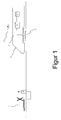
- FIG. 1 schematically shows the device 1 according to the invention, which is arranged on a rail-bound vehicle 2.
- the device 1 has a sensor 3 and an evaluation unit 4 connected thereto, which is connected to a database 5 and a transmission unit 6.
- the sensor 3 is, for example, an eddy current sensor, as it is known from US Pat WO 01/66401 A1 is known.
- the sensor continuously detects the railway sleepers during the journey, for example by means of the screw connections to the track. Knowing the speed of the rail vehicle 2, for example due to the wheel rotation speed, the distance can then be determined with knowledge of the time interval between two detected railway sleepers. This is preferably done in the evaluation unit 4, but can also be made in the sensor 3 for technical reasons.
- the information matching this threshold distance pattern is determined in the database 5, so that a unique information can be stored for each pattern.
- FIG. 1 a level crossing 7 is shown, which is connected to a receiving station 8.
- the receiving station 8 is configured to receive on and off signals to activate or deactivate the securing devices of the level crossing 7 accordingly.
- the safety devices of the level crossing 7 may be, for example, light signals or barriers, as they are known from the prior art.
- the evaluation unit 4 If now a non-standard threshold distance or a distance pattern is detected by the evaluation unit 4, the evaluation unit 4 generates a corresponding switch-on signal, which is then emitted with the aid of the transmission unit 6.
- the transfer station 8 of the level crossing 7 receives this switch-on signal and then activates the safety device of the level crossing 7.
- the transmission unit 6, which is arranged on the rail vehicle 2, can be, for example, a GSM-R data communication unit.
- the threshold distance can be recognized not only between two successive railway sleepers, but also beyond, so that even nested threshold distances can be set and detected, which increases the information density.
- the pattern can be chosen so that it does not occur accidentally elsewhere or that it is even completely unique, so that it is found at no other point in the railway network.
Landscapes
- Engineering & Computer Science (AREA)
- Mechanical Engineering (AREA)
- Train Traffic Observation, Control, And Security (AREA)
- Electric Propulsion And Braking For Vehicles (AREA)
Abstract
- Detektieren von Schwellenabständen (24) zwischen zumindest Teilen von Bahnschwellen (23) mittels mindestens einem an einem Schienenfahrzeug angeordneten Sensor (3), und
- Ermitteln der codierten Information in Abhängigkeit von den detektierten Schwellenabständen (24).
Description
- Die Erfindung betrifft ein Verfahren zur Ermittlung einer im Eisenbahngleis codierten Information. Die Erfindung betrifft auch eine Einrichtung zum Ermitteln einer im Eisenbahngleis codierten Information hierzu sowie eine entsprechende Eisenbahnschiene.
- Um den starren und unflexiblen Sicherheitsmechanismen im System Eisenbahn flexibler und somit ökonomischer zu gestalten, wird mehr und mehr versucht, bestimmte Sicherheitstechniken auf den Zug zu verlegen. Denn im Gegensatz zu streckenseitig verbauten Einrichtungen, wie beispielsweise Signalanlagen, Sensoren, Koppelspulen oder Achszähler, die sowohl in der Installation als auch in ihrer Wartung erheblich teurer sind, wird angestrebt, diese durch zugseitige Sicherungseinrichtungen zu ersetzen, die wesentlich flexibler und wartungsfreundlicher sind.
- So lässt sich unter Kenntnis der aktuellen Ortsposition beispielsweise ein Bahnübergang sichern bzw. entsichern, wenn das Schienenfahrzeug bevor es den Bahnübergang erreicht, ein entsprechendes Sicherungssignal an den Bahnübergang oder eine dafür zuständige Schaltzentrale sendet. Hierfür werden heutzutage noch entsprechende Sensoren verwendet, die im Gleisbett verlegt werden und beim Überfahren durch einen herannahenden Zug ein entsprechendes Signal an einen damit verbundenen Bahnübergang und seine Sicherungseinrichtungen sendet, so dass der Bahnübergang gesichert wird, beispielsweise durch Schließen der Schranken. In gleicher Weise muss auch ein entsprechender Sensor hinter dem Bahnübergang im Gleisbett, d. h. streckenseitig, verlegt werden, um den Bahnübergang beim Herausfahren entsprechend wieder zu entsichern. Diese so streckenseitig installierten Sensoren sind dabei sowohl in der Ausrüstung als auch in der Wartung sehr teuer und machen das System Eisenbahn unflexibel.
- Die Position eines Schienenfahrzeugs lässt sich beispielsweise mit Hilfe eines Satellitennavigationssystem ermitteln, wie beispielsweise dem GPS oder Galileo, wie dies bereits seit längerem aus dem Straßenverkehr bekannt ist. Mit Blick auf die sicherheitskritischen Anwendungen im System Eisenbahn hat jedoch ein Satellitennavigationssystem den erheblichen Nachteil, dass es keine ausfallsichere Positionsermittlung erlaubt. Denn bereits kleinere Abweichungen vom Soll-Betrieb können zu Ausfällen führen, die in dem sicherheitskritischen Bereich des Eisenbahnsystems nicht zu tolerieren sind. So kann ein hoher Baumwuchs am Rand der Strecke sowie Tunnelfahrten oder Bahnhöfe, die überdacht sind, letztlich zum Ausfall des Systems und somit zum Verlust der aktuellen Ortsposition führen, was nicht akzeptabel ist.
- Aus der
WO 01/66401 A1 - Im Lichte des o. g. ist es somit Aufgabe der vorliegenden Erfindung, ein verbessertes Verfahren und eine verbesserte Einrichtung anzugeben, mit der ein Schienenfahrzeug sicher Informationen, wie beispielsweise eine Ortsposition, ermitteln kann.
- Die vorstehende Aufgabe wird u. a. mit Hilfe des eingangs genannten Verfahrens erfindungsgemäß gelöst durch
- Detektieren von Schwellenabständen zwischen zumindest Teilen von Bahnschwellen mittels mindestens einem an dem Schienenfahrzeug angeordneten Sensor, und
- Ermitteln der codierten Information in Abhängigkeit von den detektierten Schwellenabstände.
- Erfindungsgemäß ist an dem Schienenfahrzeug mindestens ein Sensor vorgesehen, mit dessen Hilfe die Abstände zweier Bahnschwellen ermittelt werden kann. Der reguläre Schwellenabstand zweier Bahnschwellen beträgt dabei im deutschen Eisenbahnsystem ca. 65 cm. Durch eine Veränderung des Schwellenabstandes lässt sich dabei eine Information im Gleisbett codieren, die dann mit Hilfe des Sensors erkannt werden kann. In Abhängigkeit der Schwellenabstände wird somit eine Information, wie beispielsweise eine Ortsposition, ermittelt.
- Vorteilhafterweise wird ein entsprechendes Abstandsmuster mehrerer aufeinander folgender Schwellenabstände ermittelt, so dass sich mit Hilfe des Abstandsmusters ähnlich einem Binärcode eine eindeutige Information codieren und ermitteln lässt.
- Der Schwellenabstand wird zwecks Codierung einer Information derart gewählt, dass er von einem Standard-Schwellenabstand so abweicht, dass die Abweichung detektiert werden kann. So lässt sich beispielsweise ein binäres Muster mit Hilfe von abweichenden Schwellenabständen codieren, die dann als Information interpretierbar sind.
- Vorteilhafterweise werden diese Schwellenabstände beim Zusammenbau der jeweiligen Gleisabschnitte zuvor derart eingestellt, dass die gewünschte Information anhand der Schwellenabstände codiert wird.
- Anhand einer solchen im Gleisbett codierten Information lässt sich dann beispielsweise die konkrete Ortsposition, beispielsweise in Längen- und Breitengrad ermitteln.
- Ganz besonders vorteilhaft ist es dabei, wenn mit Hilfe einer so ermittelten Information ein Bahnübergang gesichert bzw. entsichert wird. Dazu werden die Bahnschwellen in dem Bereich, in dem normalerweise der entsprechende Achssensor zum Einschalten des Bahnübergangs angeordnet wird, derart verändert, dass diese Abweichung von dem Standard-Schwellenabstand von dem Sensor detektiert wird, so dass sich aus dieser Information dann ergibt, dass der Zug sich in der Nähe eines Bahnübergangs befindet. Anhand dieser so detektierten Schwellenabstand-Abweichung bzw. codierten Information wird dann ein entsprechendes Bahnübergangs-Sicherungssignal generiert, was dann an den Bahnübergang bzw. an eine für den Bahnübergang zuständige Zentrale übertragen wird.
- Dies hat dabei den entscheidenden Vorteil, dass auf dem Gleisbett verlegte Sensoren, die sehr wartungsintensiv und Witterungseinflüssen stark ausgesetzt sind, verzichtet werden kann, wobei die Verantwortung zur Sicherung des Bahnübergangs nunmehr auf den Zug verlegt wurde.
- Vorteilhafterweise kann in der Information, die mit Hilfe der Schwellenabstände im Gleisbett codiert ist, auch der Bahnübergang, der gesichert werden soll, mit codiert werden, so dass sich aus der Information der zu sichernde Bahnübergang ergibt, beispielsweise in Form einer Bahnübergangsnummer. In Abhängigkeit der aus dem Gleisbett detektierten Information wird dann der Bahnübergang ausgewählt, der von dem Schienenfahrzeug zu sichern ist.
- Die vorstehende Aufgabe wird im Übrigen auch mit einer Einrichtung der eingangs genannten Art erfindungsgemäß gelöst mit mindestens einem an dem Schienenfahrzeug angeordneten Sensor, der zum Detektieren des Schwellenabstands zwischen zumindest Teilen von Bahnschwellen eingerichtet ist, und mit einer Auswerteeinheit, die mit dem mindestens einen Sensor verbunden und zur Durchführung des vorstehenden Verfahrens eingerichtet ist.
- Vorteilhafterweise ist die Einrichtung mit einem digitalen Speicher verbunden, in dem entsprechende Abstandsmuster und deren Informationsgehalt hinterlegt sind. Wird nun ein entsprechendes vom Standard abweichendes Schwellenabstandsmuster detektiert, so kann aus dem Speicher bzw. der Datenbank dann die benötigte Information ermittelt werden.
- Darüber hinaus weist die Einrichtung vorteilhafterweise eine entsprechende Datenübertragungseinheit auf, um beim Detektieren einer Information beispielsweise einen Bahnübergang zu sichern bzw. zu entsichern.
- Die vorstehende Aufgabe wird darüber hinaus auch mit einer Eisenbahnschiene gelöst, die mindestens zwei auf einer Mehrzahl von Bahnschienen liegenden Schienenstränge aufweist, wobei zumindest ein Teil der Bahnschwellen derart angeordnet ist, dass durch die Schwellenabstände eine Information codiert wird.
- So lassen sich beispielsweise Informationen über die Kilometrierung, die heutzutage über entsprechende Kilometersteine gelöst wird, durch den Schwellenabstand codieren, so dass ein Kilometerstein nicht mehr benötigt wird und das Fahrzeug automatisch die Kilometrierung der Strecke auslesen kann.
- Die Erfindung wird anhand der beigefügten Zeichnungen beispielhaft erläutert.
- Es zeigen:
- Figur 1
- schematische Darstellung der erfindungsgemäßen Anordnung;
- Figur 2
- schematische Darstellung eines variierenden Schwellenabstandes.
-
Figur 1 zeigt schematisch die erfindungsgemäße Einrichtung 1, die auf einem schienengebundenen Fahrzeug 2 angeordnet ist. Die Einrichtung 1 weist einen Sensor 3 sowie eine damit verbundene Auswerteeinheit 4 auf, die mit einer Datenbank 5 und einer Übertragungseinheit 6 verbunden ist. - Bei dem Sensor 3 handelt es sich beispielsweise um einen Wirbelstromsensor, so wie er aus der
WO 01/66401 A1 - Unter Zugrundelegung des detektierten Schwellenabstandes zweier Bahnschwellen wird nun bei Erkennen einer jeden Bahnschwelle ermittelt, ob dieser Schwellenabstand dem standardmäßig verlegten Schwellenabstand entspricht. Denn aufgrund der automatisierten Verlegung von Eisenbahngleisen schwanken diese Schwellenabstände zwischen den einzelnen Bahnschwellen nur sehr gering, so dass eine absichtliche vergrößerte Abweichung von diesem Standard detektierbar ist. Wurde nun ein solcher nicht standardmäßiger Schwellenabstand detektiert, so kann mit Hilfe der Datenbank dann eine entsprechende Information ermittelt werden, da in dieser Datenbank 5 zu jedem Schwellenabstand bzw. Abstandsmuster eine entsprechende Information hinterlegt ist.
- Darüber hinaus ist die Auswerteeinheit 4 auch derart eingerichtet, dass sie ein entsprechendes Abstandsmuster erkennen kann. Ein solches Abstandsmuster kann dabei beispielsweise sein:
- 56 cm - 58 cm - 62 cm - 62 cm - 58 cm - 56 cm.
- Wird ein solches Schwellenabstandsmuster erkannt, so wird in der Datenbank 5 die zu diesem Schwellenabstandsmuster passende Information ermittelt, so dass für jedes Muster eine eindeutige Information hinterlegbar ist.
- Des Weiteren ist in
Figur 1 ein Bahnübergang 7 gezeigt, der mit einer Empfangsstation 8 verbunden ist. Die Empfangsstation 8 ist zum Empfangen von Ein- und Ausschaltsignalen eingerichtet, um die Sicherungseinrichtungen des Bahnübergangs 7 entsprechend zu aktivieren oder zu deaktivieren. Bei den Sicherungseinrichtungen des Bahnübergangs 7 kann es sich beispielsweise um Lichtzeichen oder Schranken handeln, so wie sie aus dem Stand der Technik bekannt sind. - Wird nun ein nicht standardmäßiger Schwellenabstand oder ein Abstandsmuster von der Auswerteeinheit 4 detektiert, so wird von der Auswerteeinheit 4 ein entsprechendes Einschaltsignal generiert, was dann mit Hilfe der Übertragungseinheit 6 ausgestrahlt wird. Die Übertragungsstation 8 des Bahnübergangs 7 empfängt dieses Einschaltsignal und aktiviert dann die Sicherheitseinrichtung des Bahnübergangs 7. Bei der Übertragungseinheit 6, die auf dem Schienenfahrzeug 2 angeordnet ist, kann es sich beispielsweise um eine GSM-R Datenkommunikationseinheit handeln.
- Denkbar ist es beispielsweise auch, dass über die Abstandsmasten der Schwellenabstände eine Bahnübergangs-Nummer codiert wird, so dass aus der entsprechenden Information dann die Nummer des Bahnübergangs extrahiert werden kann, der eingeschaltet werden soll.
-
Figur 2 zeigt schematisch einen Teil eines Gleises 21, der zwei parallel laufende Gleisstränge 22 hat, die auf entsprechenden Schwellen 23 angeordnet sind. Die Schwellen sind in einem standardmäßigen Abstand 24 angeordnet. Im deutschen Eisenbahnsystem beträgt der standardmäßige Schwellenabstand ca. 65 cm. Im Bereich 25 des Eisenbahngleises 21 weicht dieser Schwellenabstand jedoch von dem standardmäßigen Schwellenabstand 24 ab, was mit Hilfe der erfindungsgemäßen Vorrichtung und dem Verfahren detektiert werden kann. Der Schwellenabstand verändert sich hierbei derart, dass er zunächst geringer wird und dann sich wieder vergrößert, wobei das Muster beispielhaft wie folgt aussehen könnte: - 60 cm - 55 cm - 55 cm - 60 cm.
- Der Schwellenabstand kann dabei nicht nur zwischen zwei aufeinander folgenden Bahnschwellen erkannt werden, sondern auch darüber hinaus, so dass sich auch verschachtelte Schwellenabstände einstellen und detektieren lassen, was die Informationsdichte erhöht.
- Das Muster kann dabei so gewählt werden, dass es möglichst nicht zufällig an anderer Stelle auftritt oder dass es sogar vollkommen eindeutig ist, so dass es an keiner anderen Stelle im Eisenbahnnetz zu finden ist.
Claims (11)
- Verfahren zum Ermitteln einer im Eisenbahngleis (21) codierten Information gekennzeichnet durch:- Detektieren von Schwellenabständen (24) zwischen zumindest Teilen von Bahnschwellen (23) mittels mindestens einem an einem Schienenfahrzeug angeordneten Sensor (3), und- Ermitteln der codierten Information in Abhängigkeit von den detektierten Schwellenabständen (24).
- Verfahren nach Anspruch 1, gekennzeichnet durch Ermitteln der codierten Information in Abhängigkeit eines Abstandsmusters (25) mehrerer aufeinander folgender ermittelter Schwellenabstände (24).
- Verfahren nach Anspruch 1 oder 2, gekennzeichnet durch Ermitteln der codierten Information in Abhängigkeit der von einem Standard-Schwellenabstand abweichenden Schwellenabstände.
- Verfahren nach einem der vorherigen Ansprüche, bei dem die Information zuvor durch Einstellen entsprechender Schwellenabstände in das Eisenbahngleis (21) codiert wurde.
- Verfahren nach einem der vorhergehenden Ansprüche, gekennzeichnet durch Bestimmen einer Ortsposition des Schienenfahrzeuges (2) als Information in Abhängigkeit von den detektierten Schwellenabständen.
- Verfahren nach einem der vorhergehenden Ansprüche, gekennzeichnet durch Generieren eines Bahnübergangs-Sicherungssignals in Abhängigkeit der codierten Information und Übertragen des Bahnübergangs-Sicherungssignals an einen Bahnübergang (7) zum Sichern oder Entsichern von Bahnübergangs-Sicherungseinrichtungen des Bahnübergangs (7).
- Verfahren nach Anspruch 6, gekennzeichnet durch Auswählen eines zu sichernden/entsichernden Bahnübergangs (7) in Abhängigkeit von der codierten Information und Übertragen des Bahnübergangs-Sicherungssignals an den ausgewählten Bahnübergang (7).
- Einrichtung (1) zum Ermitteln einer im Eisenbahngleis (21) codierten Information mit mindestens einem an einem Schienenfahrzeug (2) angeordneten Sensor (3), der zum Detektieren von Schwellenabständen (24) zwischen zumindest Teilen von Bahnschwellen (23) eingerichtet ist, und mit einer Auswerteeinheit (4), die mit dem mindestens einen Sensor (3) verbunden und zur Durchführung des Verfahrens nach einem der vorhergehenden Ansprüche eingerichtet ist.
- Einrichtung (1) nach Anspruch 8, dadurch gekennzeichnet, dass die Einrichtung (1) weiterhin einen Speicher (5) hat, der zum Hinterlegen von Abstandsmustern und dazugehörigen Informationen, insbesondere Ortsinformationen, eingerichtet ist.
- Einrichtung (1) nach Anspruch 8 oder 9, dadurch gekennzeichnet, dass die Einrichtung (1) eine Datenübertragungseinheit (6) hat, die zum Übertragen von Bahnübergangs-Sicherungssignalen eingerichtet ist, wobei die Einrichtung zum Generieren und zum Übertragen des Bahnübergangs-Sicherungssignals in Abhängigkeit von der codierten Information eingerichtet ist.
- Eisenbahnschiene (21) aufweisend mindestens zwei auf einer Mehrzahl von Bahnschwellen (23) liegenden Schienensträngen (22), wobei zumindest ein Teil der Bahnschwellen (23) derart angeordnet sind, dass durch die Schwellenabstände eine Information codiert wird.
Applications Claiming Priority (1)
| Application Number | Priority Date | Filing Date | Title |
|---|---|---|---|
| DE201010047580 DE102010047580B4 (de) | 2010-10-07 | 2010-10-07 | Verfahren zur Ermittlung einer Information |
Publications (3)
| Publication Number | Publication Date |
|---|---|
| EP2439123A2 true EP2439123A2 (de) | 2012-04-11 |
| EP2439123A3 EP2439123A3 (de) | 2013-10-23 |
| EP2439123B1 EP2439123B1 (de) | 2014-12-17 |
Family
ID=44789275
Family Applications (1)
| Application Number | Title | Priority Date | Filing Date |
|---|---|---|---|
| EP11008147.8A Not-in-force EP2439123B1 (de) | 2010-10-07 | 2011-10-07 | Verfahren, Einrichtung und Anordnung zur Ermittlung einer im Eisenbahngleis codierten Information |
Country Status (2)
| Country | Link |
|---|---|
| EP (1) | EP2439123B1 (de) |
| DE (1) | DE102010047580B4 (de) |
Cited By (3)
| Publication number | Priority date | Publication date | Assignee | Title |
|---|---|---|---|---|
| ES2545680A1 (es) * | 2014-03-11 | 2015-09-14 | Manuel MUÑOZ SÁIZ | Sistema y procedimiento de conducción automática y de aviso de datos o señales de tráfico para trenes y vehículos rodados |
| WO2020187447A1 (de) * | 2019-03-20 | 2020-09-24 | Sew-Eurodrive Gmbh & Co. Kg | Schienensystem mit schiene, codiersystem und entlang der schiene bewegbarem mobilteil und verfahren zum betreiben eines schienensystems |
| CN118810865A (zh) * | 2023-04-21 | 2024-10-22 | 青岛海信微联信号有限公司 | 一种列车定位方法和定位设备 |
Families Citing this family (1)
| Publication number | Priority date | Publication date | Assignee | Title |
|---|---|---|---|---|
| AT525703A1 (de) | 2021-12-01 | 2023-06-15 | Track Machines Connected Ges M B H | Verfahren zur Verortung |
Citations (1)
| Publication number | Priority date | Publication date | Assignee | Title |
|---|---|---|---|---|
| WO2001066401A1 (en) | 2000-03-10 | 2001-09-13 | Bombardier Transportation Gmbh | A device and a method for determining the position of a rail-bound vehicle |
Family Cites Families (6)
| Publication number | Priority date | Publication date | Assignee | Title |
|---|---|---|---|---|
| DK85688D0 (da) * | 1988-02-19 | 1988-02-19 | Willy Palle Pedersen | Afmaerkningssystem |
| GB2222902B (en) * | 1988-09-16 | 1992-07-22 | Gec General Signal Ltd | Railway vehicle location system |
| DE19729990B4 (de) * | 1997-07-12 | 2010-12-16 | Alcatel Lucent | Verfahren und Vorrichtung zur Bestimmung der zurückgelegten Wegstrecke und der Geschwindigkeit von Schienenfahrzeugen |
| DE10114482B4 (de) * | 2001-03-24 | 2008-07-17 | Schenck Process Gmbh | Vorrichtung und Verfahren zur dynamischen Messung der Achslast oder des Gewichts von Schienenfahrzeugen |
| JP4044808B2 (ja) * | 2002-08-13 | 2008-02-06 | 邦博 岸田 | 移動体検出システム |
| US8073581B2 (en) * | 2008-11-21 | 2011-12-06 | Lockheed Martin Corporation | Efficient data acquisition for track databases |
-
2010
- 2010-10-07 DE DE201010047580 patent/DE102010047580B4/de not_active Expired - Fee Related
-
2011
- 2011-10-07 EP EP11008147.8A patent/EP2439123B1/de not_active Not-in-force
Patent Citations (1)
| Publication number | Priority date | Publication date | Assignee | Title |
|---|---|---|---|---|
| WO2001066401A1 (en) | 2000-03-10 | 2001-09-13 | Bombardier Transportation Gmbh | A device and a method for determining the position of a rail-bound vehicle |
Cited By (3)
| Publication number | Priority date | Publication date | Assignee | Title |
|---|---|---|---|---|
| ES2545680A1 (es) * | 2014-03-11 | 2015-09-14 | Manuel MUÑOZ SÁIZ | Sistema y procedimiento de conducción automática y de aviso de datos o señales de tráfico para trenes y vehículos rodados |
| WO2020187447A1 (de) * | 2019-03-20 | 2020-09-24 | Sew-Eurodrive Gmbh & Co. Kg | Schienensystem mit schiene, codiersystem und entlang der schiene bewegbarem mobilteil und verfahren zum betreiben eines schienensystems |
| CN118810865A (zh) * | 2023-04-21 | 2024-10-22 | 青岛海信微联信号有限公司 | 一种列车定位方法和定位设备 |
Also Published As
| Publication number | Publication date |
|---|---|
| EP2439123B1 (de) | 2014-12-17 |
| EP2439123A3 (de) | 2013-10-23 |
| DE102010047580A1 (de) | 2012-04-12 |
| DE102010047580B4 (de) | 2012-07-12 |
Similar Documents
| Publication | Publication Date | Title |
|---|---|---|
| EP3612430B1 (de) | Verfahren zum betreiben eines spurgebundenen verkehrssystems und vorrichtung | |
| EP3445635B1 (de) | Verfahren zum betreiben einer ortungseinrichtung sowie ortungseinrichtung | |
| EP2531391B1 (de) | Verfahren und vorrichtung zur überwachung der zugvollständigkeit | |
| WO2010121906A1 (de) | Verfahren und vorrichtung zur steuerung von eisenbahnsicherungssystemen | |
| EP4077098A1 (de) | Verfahren und überwachungssystem zur ermittlung einer position eines schienenfahrzeugs | |
| EP2250065A1 (de) | Verfahren zur signaltechnischen sicherung schienengebundener fahrzeuge und diesbezügliches sicherungssystem | |
| DE102015210427A1 (de) | Verfahren sowie Einrichtung zum Ermitteln einer Fahrerlaubnis für ein spurgebundenes Fahrzeug | |
| DE102017209928A1 (de) | Verfahren zum Betreiben eines spurgebundenen Verkehrssystems | |
| DE102011106345B4 (de) | Streckenvalidierung | |
| EP2439123B1 (de) | Verfahren, Einrichtung und Anordnung zur Ermittlung einer im Eisenbahngleis codierten Information | |
| EP3795451B1 (de) | Verfahren zum orten eines fahrzeugs an einer für einen halt des fahrzeugs vorgesehenen station | |
| WO2010060797A1 (de) | Verfahren zur kollisionswarnung und kollisionswarnsystem | |
| DE102009015540A1 (de) | Verfahren und Vorrichtung zur Geschwindigkeitsüberwachung | |
| WO2019057823A1 (de) | Verfahren zur sicherstellung, dass ein streckenblock einer eisenbahnstrecke frei von der letzten einheit eines zuges ist | |
| AT525309A1 (de) | Verfahren zum sicheren Betreiben eines Schienenverkehrssystems und Schienenverkehrssystem | |
| EP2794382B1 (de) | Verfahren und einrichtung zum erfassen von projektierungsdaten einer sensoreinrichtung zum überwachen und/oder steuern des spurgebundenen verkehrs | |
| EP3406504B1 (de) | Warnsystem für eine gleisbaustelle und verfahren zum betreiben einer gleisbaustelle | |
| EP3509925B1 (de) | Verfahren zum erstellen einer streckenpunktpassiermeldung durch einen fahrenden zug | |
| DE102006029845B4 (de) | Vorrichtung und Verfahren zur Absicherung von Streckenabschnitten eines segmentierten Fahrweges für einen schienengebundenen Fahrzeugverband | |
| DE102004024756A1 (de) | Videobasiertes Überwachungssystem und Verfahren an Gleis- oder Weichenabschnitten für die Zugschlussmeldung von Schienenfahrzeugen | |
| DE102011054422A1 (de) | Zugsicherungssystem | |
| EP1973770A1 (de) | Verfahren und vorrichtung zur zugfolgesicherung | |
| DE102007038819B4 (de) | Vorrichtung zur fahrzeugseitigen Gleisfrei- und/oder Gleisbesetztmeldung | |
| DE102021006343B4 (de) | Schutzsystem mit Sensorik für Verkehrswege | |
| EP3172108A1 (de) | Verfahren und vorrichtung zur stillstandsüberwachung |
Legal Events
| Date | Code | Title | Description |
|---|---|---|---|
| AK | Designated contracting states |
Kind code of ref document: A2 Designated state(s): AL AT BE BG CH CY CZ DE DK EE ES FI FR GB GR HR HU IE IS IT LI LT LU LV MC MK MT NL NO PL PT RO RS SE SI SK SM TR |
|
| AX | Request for extension of the european patent |
Extension state: BA ME |
|
| PUAI | Public reference made under article 153(3) epc to a published international application that has entered the european phase |
Free format text: ORIGINAL CODE: 0009012 |
|
| PUAL | Search report despatched |
Free format text: ORIGINAL CODE: 0009013 |
|
| AK | Designated contracting states |
Kind code of ref document: A3 Designated state(s): AL AT BE BG CH CY CZ DE DK EE ES FI FR GB GR HR HU IE IS IT LI LT LU LV MC MK MT NL NO PL PT RO RS SE SI SK SM TR |
|
| AX | Request for extension of the european patent |
Extension state: BA ME |
|
| RIC1 | Information provided on ipc code assigned before grant |
Ipc: B61L 15/00 20060101ALN20130918BHEP Ipc: B61L 25/02 20060101AFI20130918BHEP Ipc: B61L 29/28 20060101ALN20130918BHEP Ipc: B61L 3/12 20060101ALI20130918BHEP |
|
| 17P | Request for examination filed |
Effective date: 20140410 |
|
| RBV | Designated contracting states (corrected) |
Designated state(s): AL AT BE BG CH CY CZ DE DK EE ES FI FR GB GR HR HU IE IS IT LI LT LU LV MC MK MT NL NO PL PT RO RS SE SI SK SM TR |
|
| GRAP | Despatch of communication of intention to grant a patent |
Free format text: ORIGINAL CODE: EPIDOSNIGR1 |
|
| RIC1 | Information provided on ipc code assigned before grant |
Ipc: B61L 3/12 20060101ALI20140602BHEP Ipc: B61L 15/00 20060101ALN20140602BHEP Ipc: B61L 29/28 20060101ALN20140602BHEP Ipc: B61L 25/02 20060101AFI20140602BHEP |
|
| INTG | Intention to grant announced |
Effective date: 20140708 |
|
| RBV | Designated contracting states (corrected) |
Designated state(s): AL AT BE BG CH CY CZ DK EE ES FI FR GB GR HR HU IE IS IT LI LT LU LV MC MK MT NL NO PL PT RO RS SE SI SK SM TR |
|
| REG | Reference to a national code |
Ref country code: DE Ref legal event code: R108 |
|
| GRAS | Grant fee paid |
Free format text: ORIGINAL CODE: EPIDOSNIGR3 |
|
| REG | Reference to a national code |
Ref country code: DE Ref legal event code: R108 Effective date: 20141015 |
|
| GRAA | (expected) grant |
Free format text: ORIGINAL CODE: 0009210 |
|
| AK | Designated contracting states |
Kind code of ref document: B1 Designated state(s): AL AT BE BG CH CY CZ DK EE ES FI FR GB GR HR HU IE IS IT LI LT LU LV MC MK MT NL NO PL PT RO RS SE SI SK SM TR |
|
| REG | Reference to a national code |
Ref country code: GB Ref legal event code: FG4D Free format text: NOT ENGLISH |
|
| REG | Reference to a national code |
Ref country code: CH Ref legal event code: EP |
|
| REG | Reference to a national code |
Ref country code: IE Ref legal event code: FG4D Free format text: LANGUAGE OF EP DOCUMENT: GERMAN |
|
| REG | Reference to a national code |
Ref country code: AT Ref legal event code: REF Ref document number: 701660 Country of ref document: AT Kind code of ref document: T Effective date: 20150115 |
|
| REG | Reference to a national code |
Ref country code: CH Ref legal event code: NV Representative=s name: BRAUNPAT BRAUN EDER AG, CH |
|
| PG25 | Lapsed in a contracting state [announced via postgrant information from national office to epo] |
Ref country code: LT Free format text: LAPSE BECAUSE OF FAILURE TO SUBMIT A TRANSLATION OF THE DESCRIPTION OR TO PAY THE FEE WITHIN THE PRESCRIBED TIME-LIMIT Effective date: 20141217 Ref country code: FI Free format text: LAPSE BECAUSE OF FAILURE TO SUBMIT A TRANSLATION OF THE DESCRIPTION OR TO PAY THE FEE WITHIN THE PRESCRIBED TIME-LIMIT Effective date: 20141217 Ref country code: NO Free format text: LAPSE BECAUSE OF FAILURE TO SUBMIT A TRANSLATION OF THE DESCRIPTION OR TO PAY THE FEE WITHIN THE PRESCRIBED TIME-LIMIT Effective date: 20150317 |
|
| REG | Reference to a national code |
Ref country code: LT Ref legal event code: MG4D |
|
| PG25 | Lapsed in a contracting state [announced via postgrant information from national office to epo] |
Ref country code: LV Free format text: LAPSE BECAUSE OF FAILURE TO SUBMIT A TRANSLATION OF THE DESCRIPTION OR TO PAY THE FEE WITHIN THE PRESCRIBED TIME-LIMIT Effective date: 20141217 Ref country code: HR Free format text: LAPSE BECAUSE OF FAILURE TO SUBMIT A TRANSLATION OF THE DESCRIPTION OR TO PAY THE FEE WITHIN THE PRESCRIBED TIME-LIMIT Effective date: 20141217 Ref country code: RS Free format text: LAPSE BECAUSE OF FAILURE TO SUBMIT A TRANSLATION OF THE DESCRIPTION OR TO PAY THE FEE WITHIN THE PRESCRIBED TIME-LIMIT Effective date: 20141217 Ref country code: GR Free format text: LAPSE BECAUSE OF FAILURE TO SUBMIT A TRANSLATION OF THE DESCRIPTION OR TO PAY THE FEE WITHIN THE PRESCRIBED TIME-LIMIT Effective date: 20150318 Ref country code: SE Free format text: LAPSE BECAUSE OF FAILURE TO SUBMIT A TRANSLATION OF THE DESCRIPTION OR TO PAY THE FEE WITHIN THE PRESCRIBED TIME-LIMIT Effective date: 20141217 |
|
| PG25 | Lapsed in a contracting state [announced via postgrant information from national office to epo] |
Ref country code: NL Free format text: LAPSE BECAUSE OF FAILURE TO SUBMIT A TRANSLATION OF THE DESCRIPTION OR TO PAY THE FEE WITHIN THE PRESCRIBED TIME-LIMIT Effective date: 20141217 |
|
| PG25 | Lapsed in a contracting state [announced via postgrant information from national office to epo] |
Ref country code: EE Free format text: LAPSE BECAUSE OF FAILURE TO SUBMIT A TRANSLATION OF THE DESCRIPTION OR TO PAY THE FEE WITHIN THE PRESCRIBED TIME-LIMIT Effective date: 20141217 Ref country code: ES Free format text: LAPSE BECAUSE OF FAILURE TO SUBMIT A TRANSLATION OF THE DESCRIPTION OR TO PAY THE FEE WITHIN THE PRESCRIBED TIME-LIMIT Effective date: 20141217 Ref country code: RO Free format text: LAPSE BECAUSE OF FAILURE TO SUBMIT A TRANSLATION OF THE DESCRIPTION OR TO PAY THE FEE WITHIN THE PRESCRIBED TIME-LIMIT Effective date: 20141217 Ref country code: SK Free format text: LAPSE BECAUSE OF FAILURE TO SUBMIT A TRANSLATION OF THE DESCRIPTION OR TO PAY THE FEE WITHIN THE PRESCRIBED TIME-LIMIT Effective date: 20141217 |
|
| PG25 | Lapsed in a contracting state [announced via postgrant information from national office to epo] |
Ref country code: PL Free format text: LAPSE BECAUSE OF FAILURE TO SUBMIT A TRANSLATION OF THE DESCRIPTION OR TO PAY THE FEE WITHIN THE PRESCRIBED TIME-LIMIT Effective date: 20141217 Ref country code: IS Free format text: LAPSE BECAUSE OF FAILURE TO SUBMIT A TRANSLATION OF THE DESCRIPTION OR TO PAY THE FEE WITHIN THE PRESCRIBED TIME-LIMIT Effective date: 20150417 |
|
| PLBE | No opposition filed within time limit |
Free format text: ORIGINAL CODE: 0009261 |
|
| STAA | Information on the status of an ep patent application or granted ep patent |
Free format text: STATUS: NO OPPOSITION FILED WITHIN TIME LIMIT |
|
| PG25 | Lapsed in a contracting state [announced via postgrant information from national office to epo] |
Ref country code: DK Free format text: LAPSE BECAUSE OF FAILURE TO SUBMIT A TRANSLATION OF THE DESCRIPTION OR TO PAY THE FEE WITHIN THE PRESCRIBED TIME-LIMIT Effective date: 20141217 |
|
| 26N | No opposition filed |
Effective date: 20150918 |
|
| PG25 | Lapsed in a contracting state [announced via postgrant information from national office to epo] |
Ref country code: IT Free format text: LAPSE BECAUSE OF FAILURE TO SUBMIT A TRANSLATION OF THE DESCRIPTION OR TO PAY THE FEE WITHIN THE PRESCRIBED TIME-LIMIT Effective date: 20141217 |
|
| PG25 | Lapsed in a contracting state [announced via postgrant information from national office to epo] |
Ref country code: SI Free format text: LAPSE BECAUSE OF FAILURE TO SUBMIT A TRANSLATION OF THE DESCRIPTION OR TO PAY THE FEE WITHIN THE PRESCRIBED TIME-LIMIT Effective date: 20141217 |
|
| PG25 | Lapsed in a contracting state [announced via postgrant information from national office to epo] |
Ref country code: LU Free format text: LAPSE BECAUSE OF FAILURE TO SUBMIT A TRANSLATION OF THE DESCRIPTION OR TO PAY THE FEE WITHIN THE PRESCRIBED TIME-LIMIT Effective date: 20151007 |
|
| GBPC | Gb: european patent ceased through non-payment of renewal fee |
Effective date: 20151007 |
|
| PG25 | Lapsed in a contracting state [announced via postgrant information from national office to epo] |
Ref country code: MC Free format text: LAPSE BECAUSE OF FAILURE TO SUBMIT A TRANSLATION OF THE DESCRIPTION OR TO PAY THE FEE WITHIN THE PRESCRIBED TIME-LIMIT Effective date: 20141217 |
|
| REG | Reference to a national code |
Ref country code: IE Ref legal event code: MM4A |
|
| PG25 | Lapsed in a contracting state [announced via postgrant information from national office to epo] |
Ref country code: GB Free format text: LAPSE BECAUSE OF NON-PAYMENT OF DUE FEES Effective date: 20151007 |
|
| REG | Reference to a national code |
Ref country code: FR Ref legal event code: PLFP Year of fee payment: 6 |
|
| PG25 | Lapsed in a contracting state [announced via postgrant information from national office to epo] |
Ref country code: IE Free format text: LAPSE BECAUSE OF NON-PAYMENT OF DUE FEES Effective date: 20151007 |
|
| PG25 | Lapsed in a contracting state [announced via postgrant information from national office to epo] |
Ref country code: BG Free format text: LAPSE BECAUSE OF FAILURE TO SUBMIT A TRANSLATION OF THE DESCRIPTION OR TO PAY THE FEE WITHIN THE PRESCRIBED TIME-LIMIT Effective date: 20141217 Ref country code: SM Free format text: LAPSE BECAUSE OF FAILURE TO SUBMIT A TRANSLATION OF THE DESCRIPTION OR TO PAY THE FEE WITHIN THE PRESCRIBED TIME-LIMIT Effective date: 20141217 Ref country code: HU Free format text: LAPSE BECAUSE OF FAILURE TO SUBMIT A TRANSLATION OF THE DESCRIPTION OR TO PAY THE FEE WITHIN THE PRESCRIBED TIME-LIMIT; INVALID AB INITIO Effective date: 20111007 |
|
| PG25 | Lapsed in a contracting state [announced via postgrant information from national office to epo] |
Ref country code: CY Free format text: LAPSE BECAUSE OF FAILURE TO SUBMIT A TRANSLATION OF THE DESCRIPTION OR TO PAY THE FEE WITHIN THE PRESCRIBED TIME-LIMIT Effective date: 20141217 |
|
| PG25 | Lapsed in a contracting state [announced via postgrant information from national office to epo] |
Ref country code: BE Free format text: LAPSE BECAUSE OF NON-PAYMENT OF DUE FEES Effective date: 20151031 |
|
| PG25 | Lapsed in a contracting state [announced via postgrant information from national office to epo] |
Ref country code: MT Free format text: LAPSE BECAUSE OF FAILURE TO SUBMIT A TRANSLATION OF THE DESCRIPTION OR TO PAY THE FEE WITHIN THE PRESCRIBED TIME-LIMIT Effective date: 20141217 Ref country code: TR Free format text: LAPSE BECAUSE OF FAILURE TO SUBMIT A TRANSLATION OF THE DESCRIPTION OR TO PAY THE FEE WITHIN THE PRESCRIBED TIME-LIMIT Effective date: 20141217 |
|
| REG | Reference to a national code |
Ref country code: FR Ref legal event code: PLFP Year of fee payment: 7 |
|
| PGFP | Annual fee paid to national office [announced via postgrant information from national office to epo] |
Ref country code: FR Payment date: 20170922 Year of fee payment: 7 Ref country code: CZ Payment date: 20170927 Year of fee payment: 7 |
|
| REG | Reference to a national code |
Ref country code: AT Ref legal event code: MM01 Ref document number: 701660 Country of ref document: AT Kind code of ref document: T Effective date: 20161007 |
|
| PG25 | Lapsed in a contracting state [announced via postgrant information from national office to epo] |
Ref country code: AT Free format text: LAPSE BECAUSE OF NON-PAYMENT OF DUE FEES Effective date: 20161007 |
|
| PGFP | Annual fee paid to national office [announced via postgrant information from national office to epo] |
Ref country code: CH Payment date: 20171025 Year of fee payment: 7 |
|
| REG | Reference to a national code |
Ref country code: CH Ref legal event code: PCAR Free format text: NEW ADDRESS: HOLEESTRASSE 87, 4054 BASEL (CH) |
|
| PG25 | Lapsed in a contracting state [announced via postgrant information from national office to epo] |
Ref country code: MK Free format text: LAPSE BECAUSE OF FAILURE TO SUBMIT A TRANSLATION OF THE DESCRIPTION OR TO PAY THE FEE WITHIN THE PRESCRIBED TIME-LIMIT Effective date: 20141217 |
|
| PG25 | Lapsed in a contracting state [announced via postgrant information from national office to epo] |
Ref country code: PT Free format text: LAPSE BECAUSE OF FAILURE TO SUBMIT A TRANSLATION OF THE DESCRIPTION OR TO PAY THE FEE WITHIN THE PRESCRIBED TIME-LIMIT Effective date: 20141217 |
|
| PG25 | Lapsed in a contracting state [announced via postgrant information from national office to epo] |
Ref country code: AL Free format text: LAPSE BECAUSE OF FAILURE TO SUBMIT A TRANSLATION OF THE DESCRIPTION OR TO PAY THE FEE WITHIN THE PRESCRIBED TIME-LIMIT Effective date: 20141217 |
|
| PG25 | Lapsed in a contracting state [announced via postgrant information from national office to epo] |
Ref country code: CZ Free format text: LAPSE BECAUSE OF NON-PAYMENT OF DUE FEES Effective date: 20181007 |
|
| REG | Reference to a national code |
Ref country code: CH Ref legal event code: PL |
|
| PG25 | Lapsed in a contracting state [announced via postgrant information from national office to epo] |
Ref country code: CH Free format text: LAPSE BECAUSE OF NON-PAYMENT OF DUE FEES Effective date: 20181031 Ref country code: FR Free format text: LAPSE BECAUSE OF NON-PAYMENT OF DUE FEES Effective date: 20181031 Ref country code: LI Free format text: LAPSE BECAUSE OF NON-PAYMENT OF DUE FEES Effective date: 20181031 |