EP2439113A1 - Aufblasbarer Airbag für Fussgängeraufprall - Google Patents
Aufblasbarer Airbag für Fussgängeraufprall Download PDFInfo
- Publication number
- EP2439113A1 EP2439113A1 EP10186747A EP10186747A EP2439113A1 EP 2439113 A1 EP2439113 A1 EP 2439113A1 EP 10186747 A EP10186747 A EP 10186747A EP 10186747 A EP10186747 A EP 10186747A EP 2439113 A1 EP2439113 A1 EP 2439113A1
- Authority
- EP
- European Patent Office
- Prior art keywords
- airbag
- patch
- vent aperture
- closure arrangement
- flap
- Prior art date
- Legal status (The legal status is an assumption and is not a legal conclusion. Google has not performed a legal analysis and makes no representation as to the accuracy of the status listed.)
- Granted
Links
- 239000000463 material Substances 0.000 claims abstract description 14
- 230000003014 reinforcing effect Effects 0.000 claims description 11
- 230000002093 peripheral effect Effects 0.000 claims description 9
- 239000000853 adhesive Substances 0.000 claims description 8
- 230000001070 adhesive effect Effects 0.000 claims description 8
- 230000001419 dependent effect Effects 0.000 claims 1
- 239000004744 fabric Substances 0.000 abstract description 20
- 238000012857 repacking Methods 0.000 abstract 1
- 238000000034 method Methods 0.000 description 4
- 238000010276 construction Methods 0.000 description 2
- 230000006378 damage Effects 0.000 description 2
- 208000027418 Wounds and injury Diseases 0.000 description 1
- 238000001514 detection method Methods 0.000 description 1
- 238000002347 injection Methods 0.000 description 1
- 239000007924 injection Substances 0.000 description 1
- 208000014674 injury Diseases 0.000 description 1
- 238000012986 modification Methods 0.000 description 1
- 230000004048 modification Effects 0.000 description 1
- 230000002035 prolonged effect Effects 0.000 description 1
- 230000000717 retained effect Effects 0.000 description 1
- 238000009941 weaving Methods 0.000 description 1
Images


Classifications
-
- B—PERFORMING OPERATIONS; TRANSPORTING
- B60—VEHICLES IN GENERAL
- B60R—VEHICLES, VEHICLE FITTINGS, OR VEHICLE PARTS, NOT OTHERWISE PROVIDED FOR
- B60R21/00—Arrangements or fittings on vehicles for protecting or preventing injuries to occupants or pedestrians in case of accidents or other traffic risks
- B60R21/34—Protecting non-occupants of a vehicle, e.g. pedestrians
- B60R21/36—Protecting non-occupants of a vehicle, e.g. pedestrians using airbags
-
- B—PERFORMING OPERATIONS; TRANSPORTING
- B60—VEHICLES IN GENERAL
- B60R—VEHICLES, VEHICLE FITTINGS, OR VEHICLE PARTS, NOT OTHERWISE PROVIDED FOR
- B60R21/00—Arrangements or fittings on vehicles for protecting or preventing injuries to occupants or pedestrians in case of accidents or other traffic risks
- B60R21/02—Occupant safety arrangements or fittings, e.g. crash pads
- B60R21/16—Inflatable occupant restraints or confinements designed to inflate upon impact or impending impact, e.g. air bags
- B60R21/23—Inflatable members
- B60R21/239—Inflatable members characterised by their venting means
- B60R2021/2395—Inflatable members characterised by their venting means comprising means to control the venting
Definitions
- the present invention relates to an inflatable airbag. More particularly, the invention relates to an inflatable pedestrian airbag for a motor vehicle.
- an airbag of this general type is provided in an initially tightly folded and/or rolled package and is stored beneath a rear part of the vehicle's hood or bonnet, or beneath a cowl which is provided between the base of the windscreen and the rear part of the hood or bonnet.
- the rear of the hood or bonnet may be lifted, by a suitable air-bag, piston or other arrangement, to allow sufficient space for the pedestrian airbag to inflate so that it deploys in a manner effective to cover at least part of the windscreen and/or A-pillars of the vehicle, thereby cushioning the impact of a pedestrian with these parts of the vehicle.
- a pedestrian airbag Due to the relatively prolonged nature of a pedestrian impact accident, it is generally desirable to inflate such pedestrian airbags so that they remain inflated for a significant period of time after deployment. This is in contrast with a driver's airbag, for example, which is provided for inflation from within the hub of the vehicle's steering wheel to provide protection for the driver of the vehicle and which is typically configured to deflate as it is impacted by the driver's head and/or torso.
- an inflatable pedestrian airbag for a motor vehicle the airbag being formed of flexible material defining an inflatable chamber for the receipt of inflating gas and having a vent aperture provided with a closure arrangement, the closure arrangement having an initial closed configuration effective to substantially close the vent aperture and an alternate open configuration effective to open the vent aperture; wherein the closure arrangement is configured to remain in said closed configuration during inflation and substantially complete deployment of the airbag but to be selectively manipulable thereafter so as to adopt said open configuration and thereby permit deflation of the airbag.
- the closure arrangement is configured to remain in said closed configuration throughout deployment of the airbag and thus preferably withstands the force applied by the peak internal pressure of the inflating airbag.
- said closure arrangement is manually manipulable from said closed configuration to said open configuration.
- said closure arrangement is mechanically manipulable from said closed configuration to said open configuration.
- said closure arrangement is configured to permit said manual manipulation from outside the airbag.
- said closure arrangement comprises a flexible patch or flap arranged to cover and thereby close said vent aperture in said closed configuration.
- said patch or flap is larger than said vent aperture and is initially secured over said vent aperture on the outside of said inflatable chamber.
- said patch or flap is adhesively secured to the flexible material of said airbag, around said vent aperture, by a peripheral adhesive bond, the adhesive bond being sufficiently strong to remain substantially intact during inflation and substantially complete deployment of the airbag but to rupture as the patch or flap is subsequently peeled from the airbag.
- said patch or flap is secured to the flexible material said airbag, around said vent aperture, by a peripheral line of stitching, said line of stitching being configured to remain substantially intact during inflation and substantially complete deployment of the airbag but to rupture as the patch or flap is subsequently peeled from the airbag.
- said line of stitching comprises an inner thread and an outer thread, and is configured such that only said inner thread is exposed to said inflating gas within said inflatable chamber during inflation of the airbag.
- said inner thread has a higher tensile strength and/or is thicker than said outer thread, the outer thread being configured to break as the patch or flap is peeled from the airbag.
- said inner thread is heat resistant.
- the inner thread may thus be selected to sustain the high temperatures typically created by airbag inflating gas.
- said patch or flap is provided with a finger tab and/or a gripping aperture to facilitate convenient gripping of the patch or tab for said manual manipulation from said closed configuration to said open configuration.
- the airbag further comprises a reinforcing patch provided around the vent aperture on the inside of the inflatable chamber.
- said reinforcing patch is secured to the flexible material of the airbag by said line of stitching.
- said vent aperture takes the form of an elongate slot formed through the flexible material of the airbag.
- FIG 1 of the accompanying drawings there are illustrated two sheets 1, 2 of flexible material, most preferably fabric, from which a pedestrian airbag can be made.
- the two sheets 1, 2 are shown in figure 1 as being rectangular in form, but it is to be appreciated that the sheets can take any convenient shape or form.
- the sheets 1, 2 are superimposed and stitched together around their peripheral edges to define an inflatable chamber for the receipt of inflating gas from a gas generator in a generally conventional manner.
- this represents a very simple known method to form a basic airbag and it is important to note that the invention is not in any way restricted to airbags constructed in this manner.
- airbags in accordance with the present invention can be constructed in any convenient manner.
- the airbag can be formed via a so-called "one-piece weaving" process in which the two layers of fabric are woven simultaneously and in which the warp and weft yarns of each layer are interwoven in selected areas to create a peripheral seam.
- the rear sheet 2 is provided with a gas inlet aperture 3 through which a flow of inflating gas will be directed when the airbag is inflated, for example from an associated gas generator (not shown).
- the top or front sheet 1 is provided with a vent aperture 4, which in the embodiment illustrated takes the form of an elongate slot which is cut or otherwise formed in the fabric of the sheet 1.
- the vent aperture 4 is arranged so as to be located in spaced relation to the gas inlet aperture when the two sheets 1, 2 are connected to form the airbag.
- FIG 2 illustrates the front sheet 1 of the airbag in further detail, and shows a closure arrangement 5 which is provided in association with the vent aperture 4.
- the closure arrangement 5 illustrated comprises an elongate and generally rectangular flap or patch 6 of flexible material.
- the patch 6 is most preferably formed from similar fabric as the sheet 1 of the airbag.
- the patch 6 is shown in figure 2 in a position which is effective to cover and hence close the vent aperture 4. More particularly, it will be noted that the patch 6 is sized so as to be larger than the vent aperture 4 and is laid over the aperture 4 such that its peripheral regions lie against the front surface of the sheet 1 around the vent aperture 4.
- the patch 6 is secured to the sheet 1 in this position by a line of stitching 7 which runs around the outside of the vent aperture 4 and which serves to interconnect the fabric of the sheet 1 and the patch 6 in a generally peripheral region of the patch 6. It will be noted, however, that the line of stitching is spaced inwardly of the edge of the patch at one end such that a small tab 8 is defined at one end of the patch 6, the tab lying generally loosely against the front sheet 1 of the airbag.
- the line of stitching 7 is configured so that it will remain substantially intact during inflation and substantially complete deployment of the airbag.
- the stitching is also configured so as to be relatively weak in peel so that the patch 6 can be easily peeled off from the front surface of the sheet 1.
- the stitching is thus tuned to be relatively strong in shear but relatively weak in peel as will be described in more detail below.
- Figure 2 thus illustrates the patch 6 of the closure arrangement 5 in an initial closed configuration in which it is effective to substantially close the vent aperture 4 and prevent the leakage (or at least to prevent significant leakage) of inflating gas through the vent aperture 4 as the airbag is inflated and deployed in an accident situation.
- Figure 3 illustrates an inflated airbag 9 in the deployed condition following the injection of inflating gas into the inflatable chamber through the gas inlet aperture.
- the airbag 9 is intended to remain in this generally inflated condition (covering the windscreen and/or A-pillar of the vehicle) for some time following deployment in order to provide effective protection to any pedestrians who may be struck by the motor vehicle.
- the deployed condition of the airbag will restrict the driver's view through the windscreen of the motor vehicle. It is therefore desirable to deflate the airbag 9 so that the vehicle can be driven onward without the driver's view through the windscreen being impeded.
- the patch 6 may be conveniently pulled so that it peels away from the front sheet 1 of the airbag in order to expose and hence open the vent aperture 4, thereby permitting the flow 10 of inflating gas from inside the airbag through the vent aperture 4.
- the tab 8 provides a convenient gripping portion by which the driver or another person may grip the patch 6 and pull it away from the front surface of the inflated airbag with a peeling action, as illustrated schematically by arrow 11 in figure 4 .
- the patch 6 of the closure arrangement 5 may thus be manually manipulable from its initial closed configuration illustrated in figures 2 and 3 , to its open configuration illustrated in figure 4 , thereby opening up the vent aperture 4 and allowing deflation of the airbag so that it may be packed away for the vehicle to be driven in a so-called "limp-home" mode without the driver's visibility through the windscreen being dangerously restricted.
- the patch 6 may be printed on its outermost surface with an arrow 12 or other indicia (such as, for example, the words "PULL TAB HERE TO DEFLATE” or the like) in order to indicate the manner in which it should be peeled from the sheet 1 to open the vent aperture 4.
- an arrow 12 or other indicia such as, for example, the words "PULL TAB HERE TO DEFLATE” or the like
- the invention provides a convenient means by which the driver of the motor vehicle (or indeed any other person such as a member of the emergency services) may open the vent aperture 4 after deployment in order to permit the escape of inflating gas from inside the airbag, thereby deflating the airbag and permitting it to be packed away or otherwise secured, even if only in a temporary manner, to permit the vehicle to be safely driven onward.
- Figure 5 shows a transverse cross-section taken through the vent aperture 4 along line A-A.
- the line of stitching on either side of the vent aperture 4 is shown schematically.
- An optional internal reinforcing patch 13 is provided around the vent aperture 4.
- the reinforcing patch 13 is secured against the inner surface of the fabric sheet 1 and has a central opening which is aligned with the vent aperture 4.
- the reinforcing patch may be secured in position with the same stitching 7 (as shown) which serves to interconnect the closure patch 6 and the sheet 1.
- the reinforcing patch serves to protect the edge of the fabric sheet 1 around the vent aperture 4 and also to improve the resistance of the closure to gas leakage during inflation of the airbag.
- the location of the vent aperture 4 in spaced relation to the gas inlet aperture 3 also serves to prevent the very aggressive inflow of inflating gas from impinging directly on the vent aperture 4 and its associated closure arrangement 5.
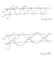
- Figure 6 shows a preferred configuration of stitch which may be used for the line of stitching 7 interconnecting the closure patch 6 and the fabric sheet 1 of the airbag.
- the stitching actually comprises two different types of thread, namely an inner thread 14 and an outer thread 15.
- the inner thread 14 is stronger than the outer thread and is preferably thicker than the outer thread.
- the inner thread is sewn through the fabric sheet 1 of the airbag and the fabric closure patch 6 in a series of successive loops 16 and will thus be exposed the inflating gas directed into the inflatable chamber of the airbag.
- the inner thread 14 is thus preferably heat resistant and is selected so as to be able to sustain the high temperatures typically created by airbag inflating gas.
- the outer thread 15 is not exposed to the inflating gas and instead runs generally along the outside of the closure patch 6, and through the successive loops formed in the inner thread 14, thereby effectively serving as a locking thread.
- the outer thread 15 therefore is therefore not required to be as resistant to heat as the inner thread 14, which means that the outer thread 15 can be weaker than the inner thread.
- the combination of the relatively strong inner thread 14 and the relatively weak outer thread 15 provides stitching which is relatively strong in shear and relatively week in peel, thereby ensuring that the closure patch 6 remains in its closed configuration during inflation and deployment of the airbag, but also ensuring that the patch can subsequently be easily peeled open. It is envisaged that the inner thread will be of M20 yarn, and the outer thread will be of M60 yarn.
- FIG. 7 illustrates an alternative configuration of stitch, which again comprises a relatively strong inner thread 14 and a relatively weak outer thread 15.
- the inner thread 15 is stitched through only the fabric sheet 1 of the airbag in a series of loops, whilst the outer thread 15 is similarly stitched through only the fabric closure patch 6.
- the two threads 14, 15 are looped around each other at positions 17 located between the fabric sheet 1 and the closure patch 6.
- This configuration of stitch is thus also arranged such that only the relatively strong thread 14 is exposed to the high temperature inflating gas inside the airbag.
- the relatively weak outer thread 15 will easily rupture.
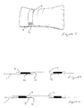
- Figure 8 illustrates a modified form of the closure patch 6 in which the end tab 8 is provided with a gripping aperture 18.
- the gripping aperture has a generally arcuate form and is sized to easily accommodate the fingers of a 90 percentile male, thereby providing a convenient means by which a person may grip the tab 8 in order to peel the closure flap 6 open.
- FIG. 9 represents transverse cross-sections taken through the vent apertures 4 of arrangements in which the closure patches 6 are instead adhesively secured to the front panel of the airbag.
- the closure patch 6 is secured to the fabric sheet 1 by a thin layer of adhesive 19 which is provided around the vent aperture 4.
- the adhesive is selected to be flexible and to be relatively strong in shear and also resistant to the high temperature created by the inflating gas, whilst also being relatively weak in peel in order to permit easy subsequent peeling of the patch 6 from the airbag.
- the inner reinforcing patch is retained, and is secured to the inner surface of the fabric sheet by stitching 20.
- the reinforcing patch 13 may also be adhesively secured in position, as exemplified by the thin layer of adhesive 21 shown between the reinforcing patch and the fabric sheet 1.
- FIG 11 illustrates an alternative form of closure arrangement.
- the vent aperture 4 is formed so as to be substantially circular.
- An annular collar 22 having an outwardly directed peripheral flange 23 is inserted through the vent aperture and is secured in position such that the flange 23 lies against the inner surface of the fabric sheet 1.
- the flange 23 may be secured to the fabric sheet 1 by way of adhesive or stitching as illustrated schematically at 24 in figure 11 .
- the annular collar 22 is externally screw threaded (at 25) and defines a flow passage 26 from the interior of the airbag.
- the flow passage 26 is initially closed by an internally screw threaded cap 27 which is sized and configured for threaded engagement with the collar 25.
- the cap 27 is initially provided in threaded engagement with the collar 25 in order to close the flow passage 26, and remains in this configuration during inflation and deployment of the airbag.
- the cap 27 can be conveniently manually unscrewed from the collar 26, thereby opening the flow passage 26 and permitting the escape therethrough of the inflating gas inside the airbag.
- vent aperture/closure arrangements falling within the scope of the present invention are also envisaged such as, for example, arrangements with frangible seams or zippers or the like.
Priority Applications (1)
| Application Number | Priority Date | Filing Date | Title |
|---|---|---|---|
| EP20100186747 EP2439113B1 (de) | 2010-10-06 | 2010-10-06 | Aufblasbarer Airbag für Fussgängeraufprall |
Applications Claiming Priority (1)
| Application Number | Priority Date | Filing Date | Title |
|---|---|---|---|
| EP20100186747 EP2439113B1 (de) | 2010-10-06 | 2010-10-06 | Aufblasbarer Airbag für Fussgängeraufprall |
Publications (2)
| Publication Number | Publication Date |
|---|---|
| EP2439113A1 true EP2439113A1 (de) | 2012-04-11 |
| EP2439113B1 EP2439113B1 (de) | 2013-06-05 |
Family
ID=43569182
Family Applications (1)
| Application Number | Title | Priority Date | Filing Date |
|---|---|---|---|
| EP20100186747 Active EP2439113B1 (de) | 2010-10-06 | 2010-10-06 | Aufblasbarer Airbag für Fussgängeraufprall |
Country Status (1)
| Country | Link |
|---|---|
| EP (1) | EP2439113B1 (de) |
Cited By (2)
| Publication number | Priority date | Publication date | Assignee | Title |
|---|---|---|---|---|
| DE202013005072U1 (de) | 2013-06-04 | 2013-07-08 | Autoliv Development Ab | Gassack mit einer adaptiven Ventilationseinrichtung und Fußgänger-Schutzeinrichtung mit einem solchen Gassack |
| JP2016168995A (ja) * | 2015-03-09 | 2016-09-23 | タカタ株式会社 | 歩行者用エアバッグ装置 |
Citations (6)
| Publication number | Priority date | Publication date | Assignee | Title |
|---|---|---|---|---|
| EP0785106A1 (de) * | 1996-01-16 | 1997-07-23 | Morton International, Inc. | Druckablass für Airbag |
| EP0835787A1 (de) * | 1996-10-09 | 1998-04-15 | TRW Occupant Restraint Systems GmbH | Gassack für ein Fahrzeuginsassen-Rückhaltesystem |
| DE10059223A1 (de) * | 2000-11-29 | 2002-07-11 | Volkswagen Ag | Sicherheitseinrichtung für eine Frontscheibe eines Kraftfahrzeugs zum Schutz von Fußgängern |
| US20060202456A1 (en) * | 2005-03-09 | 2006-09-14 | Takata Restraint Systems, Inc. | Curtain airbag with deflation mechanism |
| EP1997695A1 (de) * | 2006-02-27 | 2008-12-03 | Mazda Motor Corporation | Airbagvorrichtung |
| US20080309060A1 (en) * | 2004-08-24 | 2008-12-18 | Sam Hakki | Collision air bag and flotation system |
-
2010
- 2010-10-06 EP EP20100186747 patent/EP2439113B1/de active Active
Patent Citations (6)
| Publication number | Priority date | Publication date | Assignee | Title |
|---|---|---|---|---|
| EP0785106A1 (de) * | 1996-01-16 | 1997-07-23 | Morton International, Inc. | Druckablass für Airbag |
| EP0835787A1 (de) * | 1996-10-09 | 1998-04-15 | TRW Occupant Restraint Systems GmbH | Gassack für ein Fahrzeuginsassen-Rückhaltesystem |
| DE10059223A1 (de) * | 2000-11-29 | 2002-07-11 | Volkswagen Ag | Sicherheitseinrichtung für eine Frontscheibe eines Kraftfahrzeugs zum Schutz von Fußgängern |
| US20080309060A1 (en) * | 2004-08-24 | 2008-12-18 | Sam Hakki | Collision air bag and flotation system |
| US20060202456A1 (en) * | 2005-03-09 | 2006-09-14 | Takata Restraint Systems, Inc. | Curtain airbag with deflation mechanism |
| EP1997695A1 (de) * | 2006-02-27 | 2008-12-03 | Mazda Motor Corporation | Airbagvorrichtung |
Cited By (2)
| Publication number | Priority date | Publication date | Assignee | Title |
|---|---|---|---|---|
| DE202013005072U1 (de) | 2013-06-04 | 2013-07-08 | Autoliv Development Ab | Gassack mit einer adaptiven Ventilationseinrichtung und Fußgänger-Schutzeinrichtung mit einem solchen Gassack |
| JP2016168995A (ja) * | 2015-03-09 | 2016-09-23 | タカタ株式会社 | 歩行者用エアバッグ装置 |
Also Published As
| Publication number | Publication date |
|---|---|
| EP2439113B1 (de) | 2013-06-05 |
Similar Documents
| Publication | Publication Date | Title |
|---|---|---|
| EP3375672B1 (de) | Aufblasbarer airbag | |
| EP2502794B1 (de) | Fußgänger-Airbaganordnung | |
| EP2548772A1 (de) | Airbaganordnung | |
| EP0785106A1 (de) | Druckablass für Airbag | |
| US20080042412A1 (en) | Airbag | |
| US8235415B2 (en) | Textile gas guides for use with inflatable cushions | |
| JP5079340B2 (ja) | エアバッグ装置 | |
| US7422233B2 (en) | Air-bag | |
| EP2279101A1 (de) | Textilgasführung für entzündliche vorhänge | |
| EP2520471B1 (de) | Fußgänger-Airbaganordnung | |
| US8419059B2 (en) | Air-bag | |
| EP2607183B1 (de) | Aufblasbarer Airbag für Sicherheitseinrichtung eines Kraftfahrzeugs | |
| US9150184B2 (en) | Air bag having a slit in a border region | |
| EP2439113B1 (de) | Aufblasbarer Airbag für Fussgängeraufprall | |
| US20060202456A1 (en) | Curtain airbag with deflation mechanism | |
| EP2746112B1 (de) | Airbageinheit | |
| JP5112129B2 (ja) | エアバッグ装置 | |
| EP2452856B1 (de) | Aufblasbarer Airbag | |
| EP2765037A1 (de) | Fußgänger-Airbaganordnung | |
| EP2783924A1 (de) | Airbaganordnung | |
| EP2581275B1 (de) | Verbesserungen bei oder im Zusammenhang mit einem Airbag für eine Sicherheitsanordung eines Kraftfahrzeugs | |
| EP2520470B1 (de) | Fußgänger-Airbag | |
| JPH08301037A (ja) | 車両用エアバッグ | |
| EP2876003A1 (de) | Airbag | |
| EP2769886A1 (de) | Aufblasbarer Airbag für eine Sicherheitsvorrichtung eines Kraftfahrzeugs |
Legal Events
| Date | Code | Title | Description |
|---|---|---|---|
| AK | Designated contracting states |
Kind code of ref document: A1 Designated state(s): AL AT BE BG CH CY CZ DE DK EE ES FI FR GB GR HR HU IE IS IT LI LT LU LV MC MK MT NL NO PL PT RO RS SE SI SK SM TR |
|
| AX | Request for extension of the european patent |
Extension state: BA ME |
|
| PUAI | Public reference made under article 153(3) epc to a published international application that has entered the european phase |
Free format text: ORIGINAL CODE: 0009012 |
|
| 17P | Request for examination filed |
Effective date: 20120320 |
|
| 17Q | First examination report despatched |
Effective date: 20121107 |
|
| GRAP | Despatch of communication of intention to grant a patent |
Free format text: ORIGINAL CODE: EPIDOSNIGR1 |
|
| GRAP | Despatch of communication of intention to grant a patent |
Free format text: ORIGINAL CODE: EPIDOSNIGR1 |
|
| GRAS | Grant fee paid |
Free format text: ORIGINAL CODE: EPIDOSNIGR3 |
|
| GRAA | (expected) grant |
Free format text: ORIGINAL CODE: 0009210 |
|
| AK | Designated contracting states |
Kind code of ref document: B1 Designated state(s): AL AT BE BG CH CY CZ DE DK EE ES FI FR GB GR HR HU IE IS IT LI LT LU LV MC MK MT NL NO PL PT RO RS SE SI SK SM TR |
|
| REG | Reference to a national code |
Ref country code: GB Ref legal event code: FG4D |
|
| REG | Reference to a national code |
Ref country code: CH Ref legal event code: EP |
|
| REG | Reference to a national code |
Ref country code: AT Ref legal event code: REF Ref document number: 615479 Country of ref document: AT Kind code of ref document: T Effective date: 20130615 |
|
| REG | Reference to a national code |
Ref country code: IE Ref legal event code: FG4D |
|
| REG | Reference to a national code |
Ref country code: DE Ref legal event code: R096 Ref document number: 602010007521 Country of ref document: DE Effective date: 20130801 |
|
| REG | Reference to a national code |
Ref country code: AT Ref legal event code: MK05 Ref document number: 615479 Country of ref document: AT Kind code of ref document: T Effective date: 20130605 |
|
| PG25 | Lapsed in a contracting state [announced via postgrant information from national office to epo] |
Ref country code: AT Free format text: LAPSE BECAUSE OF FAILURE TO SUBMIT A TRANSLATION OF THE DESCRIPTION OR TO PAY THE FEE WITHIN THE PRESCRIBED TIME-LIMIT Effective date: 20130605 Ref country code: SE Free format text: LAPSE BECAUSE OF FAILURE TO SUBMIT A TRANSLATION OF THE DESCRIPTION OR TO PAY THE FEE WITHIN THE PRESCRIBED TIME-LIMIT Effective date: 20130605 Ref country code: GR Free format text: LAPSE BECAUSE OF FAILURE TO SUBMIT A TRANSLATION OF THE DESCRIPTION OR TO PAY THE FEE WITHIN THE PRESCRIBED TIME-LIMIT Effective date: 20130906 Ref country code: FI Free format text: LAPSE BECAUSE OF FAILURE TO SUBMIT A TRANSLATION OF THE DESCRIPTION OR TO PAY THE FEE WITHIN THE PRESCRIBED TIME-LIMIT Effective date: 20130605 Ref country code: LT Free format text: LAPSE BECAUSE OF FAILURE TO SUBMIT A TRANSLATION OF THE DESCRIPTION OR TO PAY THE FEE WITHIN THE PRESCRIBED TIME-LIMIT Effective date: 20130605 Ref country code: ES Free format text: LAPSE BECAUSE OF FAILURE TO SUBMIT A TRANSLATION OF THE DESCRIPTION OR TO PAY THE FEE WITHIN THE PRESCRIBED TIME-LIMIT Effective date: 20130916 Ref country code: NO Free format text: LAPSE BECAUSE OF FAILURE TO SUBMIT A TRANSLATION OF THE DESCRIPTION OR TO PAY THE FEE WITHIN THE PRESCRIBED TIME-LIMIT Effective date: 20130905 Ref country code: SI Free format text: LAPSE BECAUSE OF FAILURE TO SUBMIT A TRANSLATION OF THE DESCRIPTION OR TO PAY THE FEE WITHIN THE PRESCRIBED TIME-LIMIT Effective date: 20130605 |
|
| REG | Reference to a national code |
Ref country code: NL Ref legal event code: VDEP Effective date: 20130605 |
|
| REG | Reference to a national code |
Ref country code: LT Ref legal event code: MG4D |
|
| PG25 | Lapsed in a contracting state [announced via postgrant information from national office to epo] |
Ref country code: BG Free format text: LAPSE BECAUSE OF FAILURE TO SUBMIT A TRANSLATION OF THE DESCRIPTION OR TO PAY THE FEE WITHIN THE PRESCRIBED TIME-LIMIT Effective date: 20130905 Ref country code: RS Free format text: LAPSE BECAUSE OF FAILURE TO SUBMIT A TRANSLATION OF THE DESCRIPTION OR TO PAY THE FEE WITHIN THE PRESCRIBED TIME-LIMIT Effective date: 20130605 Ref country code: HR Free format text: LAPSE BECAUSE OF FAILURE TO SUBMIT A TRANSLATION OF THE DESCRIPTION OR TO PAY THE FEE WITHIN THE PRESCRIBED TIME-LIMIT Effective date: 20130605 |
|
| PG25 | Lapsed in a contracting state [announced via postgrant information from national office to epo] |
Ref country code: LV Free format text: LAPSE BECAUSE OF FAILURE TO SUBMIT A TRANSLATION OF THE DESCRIPTION OR TO PAY THE FEE WITHIN THE PRESCRIBED TIME-LIMIT Effective date: 20130605 |
|
| PG25 | Lapsed in a contracting state [announced via postgrant information from national office to epo] |
Ref country code: PT Free format text: LAPSE BECAUSE OF FAILURE TO SUBMIT A TRANSLATION OF THE DESCRIPTION OR TO PAY THE FEE WITHIN THE PRESCRIBED TIME-LIMIT Effective date: 20131007 Ref country code: SK Free format text: LAPSE BECAUSE OF FAILURE TO SUBMIT A TRANSLATION OF THE DESCRIPTION OR TO PAY THE FEE WITHIN THE PRESCRIBED TIME-LIMIT Effective date: 20130605 Ref country code: CZ Free format text: LAPSE BECAUSE OF FAILURE TO SUBMIT A TRANSLATION OF THE DESCRIPTION OR TO PAY THE FEE WITHIN THE PRESCRIBED TIME-LIMIT Effective date: 20130605 Ref country code: EE Free format text: LAPSE BECAUSE OF FAILURE TO SUBMIT A TRANSLATION OF THE DESCRIPTION OR TO PAY THE FEE WITHIN THE PRESCRIBED TIME-LIMIT Effective date: 20130605 Ref country code: BE Free format text: LAPSE BECAUSE OF FAILURE TO SUBMIT A TRANSLATION OF THE DESCRIPTION OR TO PAY THE FEE WITHIN THE PRESCRIBED TIME-LIMIT Effective date: 20130605 Ref country code: IS Free format text: LAPSE BECAUSE OF FAILURE TO SUBMIT A TRANSLATION OF THE DESCRIPTION OR TO PAY THE FEE WITHIN THE PRESCRIBED TIME-LIMIT Effective date: 20131005 |
|
| PG25 | Lapsed in a contracting state [announced via postgrant information from national office to epo] |
Ref country code: PL Free format text: LAPSE BECAUSE OF FAILURE TO SUBMIT A TRANSLATION OF THE DESCRIPTION OR TO PAY THE FEE WITHIN THE PRESCRIBED TIME-LIMIT Effective date: 20130605 Ref country code: RO Free format text: LAPSE BECAUSE OF FAILURE TO SUBMIT A TRANSLATION OF THE DESCRIPTION OR TO PAY THE FEE WITHIN THE PRESCRIBED TIME-LIMIT Effective date: 20130605 Ref country code: NL Free format text: LAPSE BECAUSE OF FAILURE TO SUBMIT A TRANSLATION OF THE DESCRIPTION OR TO PAY THE FEE WITHIN THE PRESCRIBED TIME-LIMIT Effective date: 20130605 |
|
| PLBE | No opposition filed within time limit |
Free format text: ORIGINAL CODE: 0009261 |
|
| STAA | Information on the status of an ep patent application or granted ep patent |
Free format text: STATUS: NO OPPOSITION FILED WITHIN TIME LIMIT |
|
| PG25 | Lapsed in a contracting state [announced via postgrant information from national office to epo] |
Ref country code: DK Free format text: LAPSE BECAUSE OF FAILURE TO SUBMIT A TRANSLATION OF THE DESCRIPTION OR TO PAY THE FEE WITHIN THE PRESCRIBED TIME-LIMIT Effective date: 20130605 |
|
| 26N | No opposition filed |
Effective date: 20140306 |
|
| PG25 | Lapsed in a contracting state [announced via postgrant information from national office to epo] |
Ref country code: IT Free format text: LAPSE BECAUSE OF FAILURE TO SUBMIT A TRANSLATION OF THE DESCRIPTION OR TO PAY THE FEE WITHIN THE PRESCRIBED TIME-LIMIT Effective date: 20130605 Ref country code: MC Free format text: LAPSE BECAUSE OF FAILURE TO SUBMIT A TRANSLATION OF THE DESCRIPTION OR TO PAY THE FEE WITHIN THE PRESCRIBED TIME-LIMIT Effective date: 20130605 |
|
| REG | Reference to a national code |
Ref country code: DE Ref legal event code: R097 Ref document number: 602010007521 Country of ref document: DE Effective date: 20140306 |
|
| REG | Reference to a national code |
Ref country code: IE Ref legal event code: MM4A |
|
| PG25 | Lapsed in a contracting state [announced via postgrant information from national office to epo] |
Ref country code: IE Free format text: LAPSE BECAUSE OF NON-PAYMENT OF DUE FEES Effective date: 20131006 |
|
| PG25 | Lapsed in a contracting state [announced via postgrant information from national office to epo] |
Ref country code: SM Free format text: LAPSE BECAUSE OF FAILURE TO SUBMIT A TRANSLATION OF THE DESCRIPTION OR TO PAY THE FEE WITHIN THE PRESCRIBED TIME-LIMIT Effective date: 20130605 |
|
| REG | Reference to a national code |
Ref country code: CH Ref legal event code: PL |
|
| PG25 | Lapsed in a contracting state [announced via postgrant information from national office to epo] |
Ref country code: TR Free format text: LAPSE BECAUSE OF FAILURE TO SUBMIT A TRANSLATION OF THE DESCRIPTION OR TO PAY THE FEE WITHIN THE PRESCRIBED TIME-LIMIT Effective date: 20130605 Ref country code: CY Free format text: LAPSE BECAUSE OF FAILURE TO SUBMIT A TRANSLATION OF THE DESCRIPTION OR TO PAY THE FEE WITHIN THE PRESCRIBED TIME-LIMIT Effective date: 20130605 |
|
| PG25 | Lapsed in a contracting state [announced via postgrant information from national office to epo] |
Ref country code: HU Free format text: LAPSE BECAUSE OF FAILURE TO SUBMIT A TRANSLATION OF THE DESCRIPTION OR TO PAY THE FEE WITHIN THE PRESCRIBED TIME-LIMIT; INVALID AB INITIO Effective date: 20101006 Ref country code: CH Free format text: LAPSE BECAUSE OF NON-PAYMENT OF DUE FEES Effective date: 20141031 Ref country code: LU Free format text: LAPSE BECAUSE OF NON-PAYMENT OF DUE FEES Effective date: 20131006 Ref country code: LI Free format text: LAPSE BECAUSE OF NON-PAYMENT OF DUE FEES Effective date: 20141031 Ref country code: MK Free format text: LAPSE BECAUSE OF FAILURE TO SUBMIT A TRANSLATION OF THE DESCRIPTION OR TO PAY THE FEE WITHIN THE PRESCRIBED TIME-LIMIT Effective date: 20130605 |
|
| PG25 | Lapsed in a contracting state [announced via postgrant information from national office to epo] |
Ref country code: MT Free format text: LAPSE BECAUSE OF FAILURE TO SUBMIT A TRANSLATION OF THE DESCRIPTION OR TO PAY THE FEE WITHIN THE PRESCRIBED TIME-LIMIT Effective date: 20130605 |
|
| REG | Reference to a national code |
Ref country code: FR Ref legal event code: PLFP Year of fee payment: 6 |
|
| REG | Reference to a national code |
Ref country code: FR Ref legal event code: PLFP Year of fee payment: 7 |
|
| REG | Reference to a national code |
Ref country code: FR Ref legal event code: PLFP Year of fee payment: 8 |
|
| PG25 | Lapsed in a contracting state [announced via postgrant information from national office to epo] |
Ref country code: AL Free format text: LAPSE BECAUSE OF FAILURE TO SUBMIT A TRANSLATION OF THE DESCRIPTION OR TO PAY THE FEE WITHIN THE PRESCRIBED TIME-LIMIT Effective date: 20130605 |
|
| REG | Reference to a national code |
Ref country code: FR Ref legal event code: PLFP Year of fee payment: 9 |
|
| PGFP | Annual fee paid to national office [announced via postgrant information from national office to epo] |
Ref country code: GB Payment date: 20231024 Year of fee payment: 14 |
|
| PGFP | Annual fee paid to national office [announced via postgrant information from national office to epo] |
Ref country code: FR Payment date: 20231026 Year of fee payment: 14 Ref country code: DE Payment date: 20231027 Year of fee payment: 14 |