EP2438964A1 - Tracer smoke generator for ventilation tests - Google Patents
Tracer smoke generator for ventilation tests Download PDFInfo
- Publication number
- EP2438964A1 EP2438964A1 EP09845459A EP09845459A EP2438964A1 EP 2438964 A1 EP2438964 A1 EP 2438964A1 EP 09845459 A EP09845459 A EP 09845459A EP 09845459 A EP09845459 A EP 09845459A EP 2438964 A1 EP2438964 A1 EP 2438964A1
- Authority
- EP
- European Patent Office
- Prior art keywords
- smoke
- containers
- tracer
- generating equipment
- row
- Prior art date
- Legal status (The legal status is an assumption and is not a legal conclusion. Google has not performed a legal analysis and makes no representation as to the accuracy of the status listed.)
- Withdrawn
Links
Images



Classifications
-
- G—PHYSICS
- G01—MEASURING; TESTING
- G01M—TESTING STATIC OR DYNAMIC BALANCE OF MACHINES OR STRUCTURES; TESTING OF STRUCTURES OR APPARATUS, NOT OTHERWISE PROVIDED FOR
- G01M99/00—Subject matter not provided for in other groups of this subclass
- G01M99/008—Subject matter not provided for in other groups of this subclass by doing functionality tests
-
- A—HUMAN NECESSITIES
- A62—LIFE-SAVING; FIRE-FIGHTING
- A62C—FIRE-FIGHTING
- A62C37/00—Control of fire-fighting equipment
- A62C37/50—Testing or indicating devices for determining the state of readiness of the equipment
-
- F—MECHANICAL ENGINEERING; LIGHTING; HEATING; WEAPONS; BLASTING
- F41—WEAPONS
- F41H—ARMOUR; ARMOURED TURRETS; ARMOURED OR ARMED VEHICLES; MEANS OF ATTACK OR DEFENCE, e.g. CAMOUFLAGE, IN GENERAL
- F41H9/00—Equipment for attack or defence by spreading flame, gas or smoke or leurres; Chemical warfare equipment
- F41H9/06—Apparatus for generating artificial fog or smoke screens
- F41H9/08—Smoke-pots without propulsive charge, i.e. stationary
-
- G—PHYSICS
- G01—MEASURING; TESTING
- G01M—TESTING STATIC OR DYNAMIC BALANCE OF MACHINES OR STRUCTURES; TESTING OF STRUCTURES OR APPARATUS, NOT OTHERWISE PROVIDED FOR
- G01M9/00—Aerodynamic testing; Arrangements in or on wind tunnels
- G01M9/02—Wind tunnels
- G01M9/04—Details
-
- G—PHYSICS
- G09—EDUCATION; CRYPTOGRAPHY; DISPLAY; ADVERTISING; SEALS
- G09B—EDUCATIONAL OR DEMONSTRATION APPLIANCES; APPLIANCES FOR TEACHING, OR COMMUNICATING WITH, THE BLIND, DEAF OR MUTE; MODELS; PLANETARIA; GLOBES; MAPS; DIAGRAMS
- G09B19/00—Teaching not covered by other main groups of this subclass
Definitions
- the present invention is encompassed in the technical field of tracer smoke generating equipment for ventilation tests, particularly for non destructive tests in existing facilities, and is especially useful in fire safety system tests.
- test systems exist for such verifications, all of which are based on generating smoke by means of equipment which allows generating smoke and conducting it to specific locations, thus simulating the generation of smoke in a fire source:
- Real fire test It is performed by means of a hydrocarbon pit. Hot exiting smoke which is the same as in a real fire situation is achieved, even though said smoke is dirty. Due to this, the real fire test has a destructive character, since many of the elements of the infrastructure or building would be damaged after the test, their repair being able to be more costly than said test itself. Furthermore, controlling the flow of smoke therein is complicated.
- Clean hot smoke test It combines the advantages of the two types of tests described above, the characteristics of this type of test are the cleanliness of the smoke thereof and this smoke is also hot smoke, and is controlled at all times. A real fire scene is therefore produced in the most accurate way possible. Nevertheless, the equipment which allows performing this type of test is complicated in terms of its structure and/or its on site assembly.
- the object of the present invention is to overcome the drawbacks of the state of the art detailed above, by means of a tracer smoke generating equipment for ventilation tests with a plurality of containers for housing at least one smoke pot, a base plate in which the containers are arranged, and collection means for collecting smoke generated by each smoke pot, characterised in that each container is sized for housing a plurality of smoke pots and comprises an upper base, a lower base, a front end, a rear end and respective side walls, an individual smoke outlet in the upper base and, an air inlet in its front end in position close to the upper base and connectable to air driving means, an upper water inlet and a lower water outlet; the containers are arranged in the base plate in a first row and a second row such that the rear ends of the containers of the first row are facing the rear ends of the containers of the second row; the base plate comprises guides for positioning each container in a predetermined position; the collection means comprise a collection box with respective smoke inlets connected to the individual smoke outlets of the containers of at least one of the rows of
- the air driving means can be respective electric fans connected to the air inlets of the containers.
- the equipment can comprise a power supply system comprising strips with respective sockets for the fans mounted on the base plate, preferably at the front, such that a socket is arranged in front of each container.
- the air inlets of the containers are preferably horizontal tubes which can comprise a guide conduit for guiding pyrotechnic initiator cables connectable to the smoke pots.
- Each individual smoke outlet can be a vertical tube emerging from the upper base of the container and the smoke inlets are arranged in the lower face of the collection box.
- the collection means preferably comprise a first collection box connected by its smoke inlets to the smoke outlets of said first row of containers and a second collection box connected to the smoke outlets of said second row of containers.
- the common smoke outlet of each collection box can be a tubular conduit emerging from the front face of the collection box.
- the containers can be filled with water through the water inlets for cooling the smoke pots. That water can then be drained by the water outlets.
- the water inlets of the containers can be provided with respective ball valves, of the faucet type.
- the water outlets of the containers can be provided with respective ball valves.
- the base plate is the platform of a trailer, which allows moving the equipment to the locations in which ventilation tests are to be carried out.
- the equipment can comprise a power supply system in the form of a PLC ("Programmable Logic Circuit") housed in a cabinet for supplying power to the electric fans.
- the PLC receives power supply from an external source and supplies it to the sockets arranged in strips mounted on the base plate in front of the front ends of the containers.
- Test programme data (fan speed and action time, etc.) can be stored in the PLC to enable adapting the equipment operation to the needs of specific test programmes.
- the supply system also comprises an electric panel made up of
- this equipment comprises to plurality of containers -1- each housing five smoke pots -2- and arranged in a base plate -3-, as well as collection means -4- for collecting smoke generated by each smoke pot -2-.
- the base plate -3- is the platform of a trailer.
- the smoke pots -2- are filled with of a mixture of known highly reactive products that once activated by the action of pyrotechnic initiator, it generates smoke and heat (approximately 300oC).
- Each container -1- comprises an upper base -1a-, a lower base -1b-, a front end -1c-, a rear end -1d- and respective side walls -1e, 1f-, an individual smoke outlet -5- in the upper base -1a- and, an air inlet -6- in its front end -1c- in a position close to its upper base -1a-.
- the smoke pots -2- can be introduced in the container -1- through the individual smoke outlet -5-.
- Each air inlet -6- is connected through a horizontal tube -6a-, to an electric fan-7-, for example of 125 W each, driving air into the container -1-.
- Each of the horizontal tubes -6a- comprises a guide conduit -13- for guiding pyrotechnic initiator cables (no shown in the drawings) connectable to the smoke pots -12-.
- Each container further comprises a lower water inlet -8- with a lower ball valve -8a- and an upper water outlet -9- with an upper ball valve-9a-.
- the containers -1- are arranged in the base plate -3- in a first row and a second row such that the rear ends -1d- of the containers -1- of the first row are facing the rear ends -1d- of the containers -1- of the second row.
- the individual smoke outlets -5- of the containers -1- are provided with respective vertical tubes -5a- emerging from the respective upper bases -1a- of the containers -1-.
- a first collection box -4- is connected by the smoke inlets -11- provided in its lower face to the smoke outlets -5- of the first row of containers -1- and a second collection box -4- is connected by the smoke inlets -11- provided in its lower face to the smoke outlets -5- of the second row of containers -1-.
- Each collection box -4- comprises a common smoke outlet -11- in the form a tubular conduit 11a emerging from its front face, through which the smoke is expelled driven by the action of the electric fans -7-.
- each vertical tube can be provided with a perimeter flange-5b- aligned with an anular reinforcement -10a- surrounding the corresponding smoke inlet -10-, with the convenient interposition of ring seal (no shown in the drawings).
- the perimeter flange-5b- can be screwed to the anular reinforcement -10a- in a known way, for example by means of screws or threaded rail sets-nuts (no shown in the drawings).
- the containers -1- are filled with water for cooling the smoke pots -2- when these are heated while generating smoke and heat.
- the water is introduced through the valve -8-.
- the level of the water contained in the containers -1- is below the plane in which the overflow -9- is located and, evidently, below the upper part of the smoke pots -2-.
- the containers -1- are filled with water for cooling the smoke pots -2- through the water inlets -9a-. The water can then be drained later through the water outlets -8-.
- the equipment comprises a power supply system -14- in the form of a PLC (Programmable Logic Circuit) housed in a cabinet for supplying electricity to the electric fans.
- the PLC receives a power supply from an outside source (not shown in the drawings) and supplies it to the sockets -14a- arranged in the strips -14- mounted on the base plate -3- in front of the front ends -1c- of the containers-1-.
- Test programme data (fan speed and action time, etc.) can be stored in the PLC in order to adapt the equipment operation to the needs of specific test programmes.
- the base plate -3- comprises a lower guide -3c-, a front guide -3d- and respective side guides -3a, 3b- emerging from the horizontal plane of the base plate -3- such that they define between each other respective housings -3e- in which the respective lower bases -1b- of the containers -1- fit.
- the containers -1- are thus arranged in predetermined positions allowing their smoke outlets -5- to be aligned with the respective smoke inlets -10- of the collection boxes -4-.
- the smoke pots -2- are placed in the respective containers -1- through the individual smoke outlets -5-.
- pyrotechnic devices the action of which will activate the smoke pots -2- are placed and the cables of the respective devices are taken out through the conduits -13-.
- the two collection boxes -4- are connected to the respective smoke outlets -5- of the rows of the containers -1-.
- the containers -1- are filled with cooling water through the respective water inlets -9- so that the water acts as cooling means for cooling the smoke pots -2-. Filling the containers -1- in an alternating manner is recommended, starting with a container from one row and continuing with the container -1- from the other row to avoid possible oscillations of the trailer supporting them.
- each container -1- is entrained by the action of the air current driven by the fans -7- towards the inside of the respective collection box -4- to which they are connected, and ejected by the common smoke outlet -11- of the collection box -4- to a smoke conductor tube-12- connected to the tubular conduit -11a- of said common outlet -11-.
- a lower ring filter-15- on which a spacer ring -16- is arranged, on which, in turn, an upper ring filter -17- is arranged.
- the filters -15, 17- respectively comprise a ring part surrounding a central sheet part with respective openings -15a, 17a- through which the smoke generated by the smoke pot -2- can penetrate but which simultaneously prevents foreign bodies from entering the inside of the pot -2- and the exit of materials from inside the pot -2-.
- Three threaded rods -19- are equidistantly welded to the outer wall of the smoke pot -2-, the upper ends of which emerge through respective through holes -18a- in respective tabs -18b- emerging from the contour of a locking ring -18-.
- respective brackets -20- are screwed in, the assembly formed by the filters -15, 17-, the spacer ring -16- and the locking ring -18- in the smoke pot -2- being thereby securely immobilised.
Landscapes
- Physics & Mathematics (AREA)
- Engineering & Computer Science (AREA)
- Business, Economics & Management (AREA)
- General Physics & Mathematics (AREA)
- Educational Administration (AREA)
- Emergency Management (AREA)
- Entrepreneurship & Innovation (AREA)
- Public Health (AREA)
- Health & Medical Sciences (AREA)
- Educational Technology (AREA)
- Theoretical Computer Science (AREA)
- Chemical & Material Sciences (AREA)
- Combustion & Propulsion (AREA)
- General Engineering & Computer Science (AREA)
- Fluid Mechanics (AREA)
- Ventilation (AREA)
Abstract
each container (1) has a smoke outlet (5) in the upper base (1a) and an air inlet (6) connectable to air driving means (7) in its front end (1c), a water outlet (8) and a water inlet (9);
the containers (1) are arranged in the base plate (3) in two rows such that the rear ends (1d) of the containers (1) of the first row are facing the rear ends (1d) of the containers (1) of the second row.
Description
- The present invention is encompassed in the technical field of tracer smoke generating equipment for ventilation tests, particularly for non destructive tests in existing facilities, and is especially useful in fire safety system tests.
- Performing more exhaustive and complex studies of fire development and ventilation analysis and smoke extraction is increasingly necessary today. Therefore, in the field of fire safety a revolution inspired by the growing social awareness towards the safety of people affected by fires has been occurring in the last few years, guided by the response of the administration in transforming rules and regulations, the progress of knowledge and related technologies. Within this revolution it is worth noting an important change in the subject of safety priority in case of fire, which has changed to focusing solely on "people", considering both the occupants of the building or infrastructure and the extinguishing and rescue services which must finally deal with the emergency.
- Research is usually conducted in different technology environments to achieve test equipment that reproduces conditions similar to those that would be produced in real life, but controlled in terms of traceability, repeatability and non-destructiveness. Performances that the systems will provide in the actual place where they are installed can be compared and verified in said manner. It is known that deviations with respect to the objectives required by regulation can occur particularly in fire safety system installation projects. Therefore, the possible error accumulated in the different steps can lead to a large deviation from the safety objectives which the designer aimed to fulfil with respect to that really achieved. Thus, on site field verification tests in service conditions of the premises object of the study are desirable. In addition, it is obvious that if the type of action to be tested is intrinsically destructive, as a fire is, a greater difficulty arises at the time of considering a field test producing the effects with which the study premise is to be affected. The on site check by means of tests is, therefore, an efficient tool for verifying the fire safety systems.
- Basically, the following test systems exist for such verifications, all of which are based on generating smoke by means of equipment which allows generating smoke and conducting it to specific locations, thus simulating the generation of smoke in a fire source:
- Cold test of clean smoke: This system has the advantage that the smoke is completely clean but its results are not accurate. The great problem of this type test is that the temperature of the exiting smoke tends to be around 40ºC, such that it can be considered that the smoke generated is cold smoke and, therefore, a rise and stratification thereof is not achieved and therefore a fire scene is not produced in a realistic way.
- Real fire test: It is performed by means of a hydrocarbon pit. Hot exiting smoke which is the same as in a real fire situation is achieved, even though said smoke is dirty. Due to this, the real fire test has a destructive character, since many of the elements of the infrastructure or building would be damaged after the test, their repair being able to be more costly than said test itself. Furthermore, controlling the flow of smoke therein is complicated.
- Clean hot smoke test: It combines the advantages of the two types of tests described above, the characteristics of this type of test are the cleanliness of the smoke thereof and this smoke is also hot smoke, and is controlled at all times. A real fire scene is therefore produced in the most accurate way possible. Nevertheless, the equipment which allows performing this type of test is complicated in terms of its structure and/or its on site assembly.
- The object of the present invention is to overcome the drawbacks of the state of the art detailed above, by means of a tracer smoke generating equipment for ventilation tests with a plurality of containers for housing at least one smoke pot, a base plate in which the containers are arranged, and collection means for collecting smoke generated by each smoke pot, characterised in that
each container is sized for housing a plurality of smoke pots and comprises an upper base, a lower base, a front end, a rear end and respective side walls, an individual smoke outlet in the upper base and, an air inlet in its front end in position close to the upper base and connectable to air driving means, an upper water inlet and a lower water outlet;
the containers are arranged in the base plate in a first row and a second row such that the rear ends of the containers of the first row are facing the rear ends of the containers of the second row;
the base plate comprises guides for positioning each container in a predetermined position;
the collection means comprise a collection box with respective smoke inlets connected to the individual smoke outlets of the containers of at least one of the rows of containers, and a common smoke outlet connectable to smoke conducting means. - The air driving means can be respective electric fans connected to the air inlets of the containers. For supplying electricity to these fans, the equipment can comprise a power supply system comprising strips with respective sockets for the fans mounted on the base plate, preferably at the front, such that a socket is arranged in front of each container. The air inlets of the containers are preferably horizontal tubes which can comprise a guide conduit for guiding pyrotechnic initiator cables connectable to the smoke pots.
- Each individual smoke outlet can be a vertical tube emerging from the upper base of the container and the smoke inlets are arranged in the lower face of the collection box. The collection means preferably comprise a first collection box connected by its smoke inlets to the smoke outlets of said first row of containers and a second collection box connected to the smoke outlets of said second row of containers. The common smoke outlet of each collection box can be a tubular conduit emerging from the front face of the collection box.
- The containers can be filled with water through the water inlets for cooling the smoke pots. That water can then be drained by the water outlets. The water inlets of the containers can be provided with respective ball valves, of the faucet type. Likewise, the water outlets of the containers can be provided with respective ball valves.
- In a preferred embodiment of the invention, the base plate is the platform of a trailer, which allows moving the equipment to the locations in which ventilation tests are to be carried out.
- The equipment can comprise a power supply system in the form of a PLC ("Programmable Logic Circuit") housed in a cabinet for supplying power to the electric fans. The PLC receives power supply from an external source and supplies it to the sockets arranged in strips mounted on the base plate in front of the front ends of the containers. Test programme data (fan speed and action time, etc.) can be stored in the PLC to enable adapting the equipment operation to the needs of specific test programmes.
- In a practical embodiment, the supply system also comprises an electric panel made up of
- Auto-transformer
- Relay fans
- Thermal differential and magneto
- 220V supply inlet
- Due to the need of supplying power to this panel (which in turn supplies the fans of the containers), there is a 220 V female Schuko which must be plugged into a power source. The most convenient alternative is that of using a male-male extension from the electric panel of the heat generating equipment to that of the tracer smoke generating trailer when both parts work together.
- It can be observed that the tracer smoke generating equipment efficiently overcomes the drawbacks of the state of the art by means of highly efficient equipment, of great structural simplicity and easy assembly and handling.
- Aspects and embodiments of the invention are described below based on several drawings, in which
-
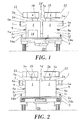
Figure 1 is a schematic front elevational view of an embodiment of the equipment according to the present invention: -
Figure 2 is a schematic rear elevational view of the equipment shown inFigure 1 ; -
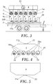
Figure 3 is side schematic view of the equipment shown inFigure 1 ; -
Figure 4 is a schematic lower plan view of the collection box shown inFigure 1 ; -
Figure 5 is a schematic upper plan view of the collection box shown inFigure 1 ; -
Figure 6 is a schematic front elevational view of one of the containers forming part of the equipment shown inFigure 1 ; -
Figure 7 is a schematic side elevational view of one of the containers forming part of the equipment shown inFigure 1 ; -
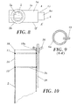
Figure 8 is a schematic upper plan view of the container shown inFigure 7 ; -
Figure 9 is a schematic cross section view of the horizontal tube of the container shown inFigure 7 ; -
Figure 10 is a schematic cross section view of an embodiment of a smoke pot of those which can be housed in the containers of the equipment according to the present invention; -
Figure 11 is a schematic upper plan view of the closing element for the smoke pot shown inFigure 10 ; -
Figure 12 is a schematic upper plan view of the upper filter for the smoke pot shown inFigure 10 ; -
Figure 13 is a schematic upper plan view of the spacer ring for the smoke pot shown inFigure 10 ; -
Figure 14 is a schematic upper plan view of the lower filter for the smoke pot shown inFigure 10 ; -
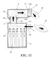
Figure 15 is a side sectional view of the container shown inFigure 7 and of one of the collection boxes shown inFigure 1 ; -
Figure 16 is an upper plan view of an embodiment of the base plate forming part of the equipment shown inFigure 1 . - These figures contain numerical references identifying the following elements:
- 1
- container
- 1a
- upper base
- 1b
- lower base
- 1c
- front end
- 1d
- rear end
- 1e, 1f
- side walls
- 2
- smoke pot
- 2a
- upper opening of the smoke pot
- 3
- base plate
- 3a, 3b, 3c, 3d
- guides
- 3e
- housings
- 4
- collection box
- 5
- individual smoke outlet
- 5a
- vertical tube
- 5b
- perimeter flange
- 6
- air inlet
- 6a
- horizontal tube
- 7
- electric fan
- 8
- lower water outlet
- 8a
- ball valve
- 9
- upper water inlet
- 9a
- ball valve
- 10
- smoke inlet
- 10a
- anular reinforcement
- 11
- common outlet
- 11a
- tubular conduit
- 12
- smoke conductor tube
- 13
- guide conduit
- 14
- power supply system
- 14a
- strip
- 14b
- socket
- 15
- lower filter
- 15a
- opening
- 16
- spacer ring
- 17
- upper filter
- 17a
- opening
- 18
- closing ring
- 18a
- through hole
- 18b
- tab
- 19
- threaded rod
- 20
- bracket
- As can be seen in the embodiment of the of tracer smoke generating equipment for ventilation tests shown in
Figures 1 to 9, 15 and 16 , this equipment comprises to plurality of containers -1- each housing five smoke pots -2- and arranged in a base plate -3-, as well as collection means -4- for collecting smoke generated by each smoke pot -2-. The base plate -3- is the platform of a trailer. The smoke pots -2- are filled with of a mixture of known highly reactive products that once activated by the action of pyrotechnic initiator, it generates smoke and heat (approximately 300ºC). - Each container -1- comprises an upper base -1a-, a lower base -1b-, a front end -1c-, a rear end -1d- and respective side walls -1e, 1f-, an individual smoke outlet -5- in the upper base -1a- and, an air inlet -6- in its front end -1c- in a position close to its upper base -1a-. The smoke pots -2- can be introduced in the container -1- through the individual smoke outlet -5-. Each air inlet -6- is connected through a horizontal tube -6a-, to an electric fan-7-, for example of 125 W each, driving air into the container -1-. Each of the horizontal tubes -6a- comprises a guide conduit -13- for guiding pyrotechnic initiator cables (no shown in the drawings) connectable to the smoke pots -12-.
- Each container further comprises a lower water inlet -8- with a lower ball valve -8a- and an upper water outlet -9- with an upper ball valve-9a-. The containers -1- are arranged in the base plate -3- in a first row and a second row such that the rear ends -1d- of the containers -1- of the first row are facing the rear ends -1d- of the containers -1- of the second row. The individual smoke outlets -5- of the containers -1- are provided with respective vertical tubes -5a- emerging from the respective upper bases -1a- of the containers -1-.
- A first collection box -4- is connected by the smoke inlets -11- provided in its lower face to the smoke outlets -5- of the first row of containers -1- and a second collection box -4- is connected by the smoke inlets -11- provided in its lower face to the smoke outlets -5- of the second row of containers -1-. Each collection box -4- comprises a common smoke outlet -11- in the form a
tubular conduit 11a emerging from its front face, through which the smoke is expelled driven by the action of the electric fans -7-. For securely joining the smoke inlets -10- of the box -4- to the vertical tubes -5a- of the containers -1-, each vertical tube can be provided with a perimeter flange-5b- aligned with an anular reinforcement -10a- surrounding the corresponding smoke inlet -10-, with the convenient interposition of ring seal (no shown in the drawings). The perimeter flange-5b- can be screwed to the anular reinforcement -10a- in a known way, for example by means of screws or threaded rail sets-nuts (no shown in the drawings). - As seen in
Figure 15 , the containers -1- are filled with water for cooling the smoke pots -2- when these are heated while generating smoke and heat. The water is introduced through the valve -8-. The level of the water contained in the containers -1- is below the plane in which the overflow -9- is located and, evidently, below the upper part of the smoke pots -2-.The containers -1- are filled with water for cooling the smoke pots -2- through the water inlets -9a-. The water can then be drained later through the water outlets -8-. - The equipment comprises a power supply system -14- in the form of a PLC (Programmable Logic Circuit) housed in a cabinet for supplying electricity to the electric fans. The PLC receives a power supply from an outside source (not shown in the drawings) and supplies it to the sockets -14a- arranged in the strips -14- mounted on the base plate -3- in front of the front ends -1c- of the containers-1-. Test programme data (fan speed and action time, etc.) can be stored in the PLC in order to adapt the equipment operation to the needs of specific test programmes.
- As can seen in
Figure 16 , the base plate -3- comprises a lower guide -3c-, a front guide -3d- and respective side guides -3a, 3b- emerging from the horizontal plane of the base plate -3- such that they define between each other respective housings -3e- in which the respective lower bases -1b- of the containers -1- fit. The containers -1- are thus arranged in predetermined positions allowing their smoke outlets -5- to be aligned with the respective smoke inlets -10- of the collection boxes -4-. - To prepare the equipment, first the smoke pots -2- are placed in the respective containers -1- through the individual smoke outlets -5-. Next pyrotechnic devices the action of which will activate the smoke pots -2- are placed and the cables of the respective devices are taken out through the conduits -13-. Then the two collection boxes -4- are connected to the respective smoke outlets -5- of the rows of the containers -1-. Next, the containers -1- are filled with cooling water through the respective water inlets -9- so that the water acts as cooling means for cooling the smoke pots -2-. Filling the containers -1- in an alternating manner is recommended, starting with a container from one row and continuing with the container -1- from the other row to avoid possible oscillations of the trailer supporting them. Subsequently, the pyrotechnic devices are switched on to therefore activate the generation of smoke by the smoke pots -2-. The smoke generated in each container -1- is entrained by the action of the air current driven by the fans -7- towards the inside of the respective collection box -4- to which they are connected, and ejected by the common smoke outlet -11- of the collection box -4- to a smoke conductor tube-12- connected to the tubular conduit -11a- of said common outlet -11-.
- In the embodiment shown in
Figures 10-14 , in the upper opening -2a-of the smoke pot -2- there is arranged a lower ring filter-15-, on which a spacer ring -16- is arranged, on which, in turn, an upper ring filter -17- is arranged. The filters -15, 17- respectively comprise a ring part surrounding a central sheet part with respective openings -15a, 17a- through which the smoke generated by the smoke pot -2- can penetrate but which simultaneously prevents foreign bodies from entering the inside of the pot -2- and the exit of materials from inside the pot -2-. - Three threaded rods -19- are equidistantly welded to the outer wall of the smoke pot -2-, the upper ends of which emerge through respective through holes -18a- in respective tabs -18b- emerging from the contour of a locking ring -18-. At the upper ends of the three rods -19- respective brackets -20- are screwed in, the assembly formed by the filters -15, 17-, the spacer ring -16- and the locking ring -18- in the smoke pot -2- being thereby securely immobilised.
Claims (11)
- Tracer smoke generating equipment for ventilation tests with a plurality of containers (1) for housing at least one smoke pot (2), a base plate (3) in which the containers (1) are arranged, and collection means (4) for collecting smoke generated by each smoke pot (2), characterised in that
each container (1) is sized for housing a plurality of smoke pots (2) and comprises an upper base (1a), a lower base (1b), a front end (1c), a rear end (1d) and respective side walls (1e, 1f), an individual smoke outlet (5) in the upper base (1a) and an air inlet (6) in its front end (1c) in a position close to the upper base (1a) and connectable to air driving means (7), a lower water outlet (8) and an upper water inlet (9);
the containers (1) are arranged in the base plate (3) in a first row and a second row such that the rear ends (1d) of the containers (1) of the first row are facing the rear ends (1d) of the containers (1) of the second row;
the base plate (3) comprises guides (3a, 3b, 3c, 3d) for positioning each container (1) in a predetermined position;
the collection means (4) comprise a collection box (4) with respective smoke inlets (10) connected to the individual smoke outlets (5) of the containers (1) of at least one of the rows of containers (1), and a common smoke outlet (11) connectable to smoke conducting means (12). - Tracer smoke generating equipment according to claim 1, characterised in that each individual smoke outlet is a vertical tube (5a) emerging from the upper base (1a) of the container (1) and the smoke inlets (10) are arranged in the lower face of the collection box (4).
- Tracer smoke generating equipment according to claim 1 or 2, characterised in that the air inlet (6) of each container is a horizontal tube (6a).
- Tracer smoke generating equipment according to claim 3, characterised in that the horizontal tube (6a) comprises a guide conduit (13) for guiding pyrotechnic initiator cables connectable to the smoke pots (2).
- Tracer smoke generating equipment according to any one of the preceding claims, characterised in that the base plate (3) is a platform of a trailer.
- Tracer smoke generating equipment according to any one of the preceding claims, characterised in that the air driving means (7) are respective electric fans (7) connected to the air inlets (6) of the containers (1).
- Tracer smoke generating equipment according to claim 6, characterised in that it comprises a power supply system (14) comprising strips (14a) with respective sockets (14b) for said fans (7) mounted on the base plate.
- Tracer smoke generating equipment according to any one of the preceding claims, characterised in that the water inlets (9) of the containers (1) are provided with respective ball valves (9a).
- Tracer generating equipment according to any one of the preceding claims, characterised in that the water outlets (8) of the containers (1) are provided with respective ball valves (8a).
- Tracer smoke generating equipment, according to any one of the preceding claims, characterised in that the common smoke outlet (11) of the collection box (4) is a tubular conduit (11a) emerging from the front face of the collection box (4).
- Tracer smoke generating equipment according to any one of the preceding claims, characterised in that the collection means (4) comprise a first collection box (4) connected by its smoke inlets (11) to the smoke outlets (5) of said first row of containers (1) and a second collection box (4) connected by its smoke inlets (11) to the smoke outlets (5) of said second row of containers (1).
Applications Claiming Priority (1)
| Application Number | Priority Date | Filing Date | Title |
|---|---|---|---|
| PCT/ES2009/070203 WO2010139815A1 (en) | 2009-06-03 | 2009-06-03 | Tracer smoke generator for ventilation tests |
Publications (2)
| Publication Number | Publication Date |
|---|---|
| EP2438964A1 true EP2438964A1 (en) | 2012-04-11 |
| EP2438964A4 EP2438964A4 (en) | 2015-03-11 |
Family
ID=43297296
Family Applications (1)
| Application Number | Title | Priority Date | Filing Date |
|---|---|---|---|
| EP09845459.8A Withdrawn EP2438964A4 (en) | 2009-06-03 | 2009-06-03 | Tracer smoke generator for ventilation tests |
Country Status (2)
| Country | Link |
|---|---|
| EP (1) | EP2438964A4 (en) |
| WO (1) | WO2010139815A1 (en) |
Cited By (3)
| Publication number | Priority date | Publication date | Assignee | Title |
|---|---|---|---|---|
| CN104849634A (en) * | 2015-05-19 | 2015-08-19 | 国家电网公司 | Insulator natural contamination deposit simulation system |
| EP3408637A4 (en) * | 2016-01-25 | 2019-09-25 | Jacobs Technology Inc. | TRANSPORTABLE BLOWERS |
| CN110354436A (en) * | 2019-07-30 | 2019-10-22 | 江苏建筑职业技术学院 | A kind of structural fire protection assembly detection apparatus |
Families Citing this family (5)
| Publication number | Priority date | Publication date | Assignee | Title |
|---|---|---|---|---|
| CZ2011883A3 (en) * | 2011-12-27 | 2013-07-31 | K.B.K. Fire, S.R.O. | Method of verifying functionality of fire ventilation and apparatus for making the same |
| DE102012000376B4 (en) | 2012-01-12 | 2013-08-14 | Ebm-Papst St. Georgen Gmbh & Co. Kg | Axial or diagonal fan |
| CN107290128B (en) * | 2017-08-23 | 2023-12-01 | 公安部天津消防研究所 | Air flow state tracing device at carriage window and experimental method |
| CN109718497B (en) * | 2019-02-25 | 2024-01-23 | 志纳电器有限公司 | Automatic inspection control equipment of fire pump |
| CN114459294B (en) * | 2021-12-29 | 2023-07-14 | 宜昌测试技术研究所 | An air-dispersed cold smoke dispensing device |
Family Cites Families (5)
| Publication number | Priority date | Publication date | Assignee | Title |
|---|---|---|---|---|
| US5173052A (en) * | 1991-09-17 | 1992-12-22 | Duncan Associates, Inc. | Fire safety training trailer for children |
| FR2750783B1 (en) * | 1996-07-03 | 1998-11-06 | Lacroix Soc E | SMOKE GENERATING DETERRENCE SYSTEM |
| ES2239518B1 (en) * | 2003-10-03 | 2006-11-01 | Fundacion Labein | SAFETY TEST EQUIPMENT BEFORE FIRE THROUGH CLEAN HOT SMOKE. |
| US7578225B2 (en) * | 2005-12-02 | 2009-08-25 | Garrett Bosch | Smoke generator machine |
| ES2302492B1 (en) * | 2008-04-18 | 2009-03-16 | Trabajos Tecnicos Y Cientificos, S.L. | SYSTEM FOR VERIFICATION OF THE EVACUATION OF SMOKE AND HEAT IN FIRE PRODUCED IN CLOSED SPACES. |
-
2009
- 2009-06-03 WO PCT/ES2009/070203 patent/WO2010139815A1/en not_active Ceased
- 2009-06-03 EP EP09845459.8A patent/EP2438964A4/en not_active Withdrawn
Cited By (3)
| Publication number | Priority date | Publication date | Assignee | Title |
|---|---|---|---|---|
| CN104849634A (en) * | 2015-05-19 | 2015-08-19 | 国家电网公司 | Insulator natural contamination deposit simulation system |
| EP3408637A4 (en) * | 2016-01-25 | 2019-09-25 | Jacobs Technology Inc. | TRANSPORTABLE BLOWERS |
| CN110354436A (en) * | 2019-07-30 | 2019-10-22 | 江苏建筑职业技术学院 | A kind of structural fire protection assembly detection apparatus |
Also Published As
| Publication number | Publication date |
|---|---|
| EP2438964A4 (en) | 2015-03-11 |
| WO2010139815A1 (en) | 2010-12-09 |
Similar Documents
| Publication | Publication Date | Title |
|---|---|---|
| US11364401B2 (en) | Automatic control type hot smoke testing system | |
| WO2010139815A1 (en) | Tracer smoke generator for ventilation tests | |
| KR102474556B1 (en) | System for Monitoring File of Underground Power Line Connected to a Transformer of New Town | |
| CN113644568A (en) | Outdoor fireproof transformer substation | |
| CN103390868B (en) | A kind of buried substation of safe and intelligent | |
| CN204008014U (en) | Condenser copper tube leak detector | |
| RU2433354C1 (en) | Electric circulation system of water heating | |
| CN101928579B (en) | Installing method of dry quenching fire automatic alarm system | |
| CN209088620U (en) | A kind of power distribution automation monitor terminal | |
| EP1275910B1 (en) | Boiler unit | |
| CN102716558A (en) | Fire-extinguishing system special for wind driven generator cabin | |
| GB2409894A (en) | Boiler unit with removable support rails | |
| EP4026963B1 (en) | Modular building construction system | |
| CN106877215A (en) | Fire-proof type distribution cabinet is installed in the convenient lifting of one kind | |
| CN110285992A (en) | A fire extinguishing performance test device and operation method of a comprehensive utility gallery fire protection system | |
| CN104837319A (en) | Heat radiation control method for electrical cabinets in power distribution room | |
| CN204681116U (en) | Skid-mounted type charging station | |
| KR102532518B1 (en) | Fixing Apparatus for Underground Cable Installed Transformer | |
| CN107424501B (en) | Automatic pay-off fuming device | |
| KR102510251B1 (en) | System for Protecting Supply of Underground Power Line Connected to a Transformer | |
| CN104005423B (en) | A kind of normal pressure underground work well security protection work system and method to set up thereof | |
| KR102551025B1 (en) | System for Detecting Railroad Fire of Underground Distribution Line Connected to Transformer | |
| CN221612753U (en) | Cable heat resistance test box | |
| CN203874905U (en) | Horizontal electrostatic lampblack removing equipment with separated main engine and control electric cabinet | |
| CN105451502B (en) | Module assembling independence cabinet channel obturator |
Legal Events
| Date | Code | Title | Description |
|---|---|---|---|
| PUAI | Public reference made under article 153(3) epc to a published international application that has entered the european phase |
Free format text: ORIGINAL CODE: 0009012 |
|
| 17P | Request for examination filed |
Effective date: 20111228 |
|
| AK | Designated contracting states |
Kind code of ref document: A1 Designated state(s): AT BE BG CH CY CZ DE DK EE ES FI FR GB GR HR HU IE IS IT LI LT LU LV MC MK MT NL NO PL PT RO SE SI SK TR |
|
| DAX | Request for extension of the european patent (deleted) | ||
| A4 | Supplementary search report drawn up and despatched |
Effective date: 20150210 |
|
| RIC1 | Information provided on ipc code assigned before grant |
Ipc: G09B 19/00 20060101ALI20150204BHEP Ipc: F41H 9/06 20060101AFI20150204BHEP Ipc: A62C 37/50 20060101ALI20150204BHEP Ipc: G01M 99/00 20110101ALI20150204BHEP Ipc: G01M 9/04 20060101ALI20150204BHEP |
|
| RAP1 | Party data changed (applicant data changed or rights of an application transferred) |
Owner name: FUNDACION TECNALIA RESEARCH & INNOVATION |
|
| STAA | Information on the status of an ep patent application or granted ep patent |
Free format text: STATUS: THE APPLICATION IS DEEMED TO BE WITHDRAWN |
|
| 18D | Application deemed to be withdrawn |
Effective date: 20150910 |