EP2438937A1 - Blood pump - Google Patents
Blood pump Download PDFInfo
- Publication number
- EP2438937A1 EP2438937A1 EP20110010004 EP11010004A EP2438937A1 EP 2438937 A1 EP2438937 A1 EP 2438937A1 EP 20110010004 EP20110010004 EP 20110010004 EP 11010004 A EP11010004 A EP 11010004A EP 2438937 A1 EP2438937 A1 EP 2438937A1
- Authority
- EP
- European Patent Office
- Prior art keywords
- pump
- stator
- rotor
- motor
- radial bearing
- Prior art date
- Legal status (The legal status is an assumption and is not a legal conclusion. Google has not performed a legal analysis and makes no representation as to the accuracy of the status listed.)
- Granted
Links
- 239000008280 blood Substances 0.000 title claims abstract description 64
- 210000004369 blood Anatomy 0.000 title claims abstract description 64
- 239000012530 fluid Substances 0.000 claims abstract description 29
- 238000005086 pumping Methods 0.000 claims description 18
- 230000005291 magnetic effect Effects 0.000 claims description 13
- 230000009471 action Effects 0.000 claims description 2
- 239000000696 magnetic material Substances 0.000 claims 1
- 230000017531 blood circulation Effects 0.000 abstract description 3
- 239000000463 material Substances 0.000 description 24
- 210000000709 aorta Anatomy 0.000 description 15
- 210000005240 left ventricle Anatomy 0.000 description 13
- 238000004804 winding Methods 0.000 description 12
- 210000002216 heart Anatomy 0.000 description 11
- 210000001147 pulmonary artery Anatomy 0.000 description 10
- 210000005241 right ventricle Anatomy 0.000 description 10
- RTAQQCXQSZGOHL-UHFFFAOYSA-N Titanium Chemical compound [Ti] RTAQQCXQSZGOHL-UHFFFAOYSA-N 0.000 description 9
- 239000010936 titanium Substances 0.000 description 9
- 208000015181 infectious disease Diseases 0.000 description 8
- 230000002861 ventricular Effects 0.000 description 8
- 238000002618 extracorporeal membrane oxygenation Methods 0.000 description 7
- 229910052719 titanium Inorganic materials 0.000 description 7
- XEEYBQQBJWHFJM-UHFFFAOYSA-N Iron Chemical compound [Fe] XEEYBQQBJWHFJM-UHFFFAOYSA-N 0.000 description 6
- 230000002685 pulmonary effect Effects 0.000 description 6
- 230000010100 anticoagulation Effects 0.000 description 5
- 238000013461 design Methods 0.000 description 5
- 230000004907 flux Effects 0.000 description 5
- 210000003709 heart valve Anatomy 0.000 description 5
- 229910001220 stainless steel Inorganic materials 0.000 description 5
- 239000010935 stainless steel Substances 0.000 description 5
- 238000012360 testing method Methods 0.000 description 5
- 239000004809 Teflon Substances 0.000 description 4
- 229920006362 Teflon® Polymers 0.000 description 4
- 239000000560 biocompatible material Substances 0.000 description 4
- 239000000919 ceramic Substances 0.000 description 4
- 238000000576 coating method Methods 0.000 description 4
- 238000010276 construction Methods 0.000 description 4
- 238000011161 development Methods 0.000 description 4
- 229910001172 neodymium magnet Inorganic materials 0.000 description 4
- 210000005245 right atrium Anatomy 0.000 description 4
- OKTJSMMVPCPJKN-UHFFFAOYSA-N Carbon Chemical compound [C] OKTJSMMVPCPJKN-UHFFFAOYSA-N 0.000 description 3
- RYGMFSIKBFXOCR-UHFFFAOYSA-N Copper Chemical compound [Cu] RYGMFSIKBFXOCR-UHFFFAOYSA-N 0.000 description 3
- 208000007536 Thrombosis Diseases 0.000 description 3
- 229910052799 carbon Inorganic materials 0.000 description 3
- 208000014674 injury Diseases 0.000 description 3
- 238000003780 insertion Methods 0.000 description 3
- 230000037431 insertion Effects 0.000 description 3
- 229910052742 iron Inorganic materials 0.000 description 3
- 230000007774 longterm Effects 0.000 description 3
- 230000013011 mating Effects 0.000 description 3
- 230000000541 pulsatile effect Effects 0.000 description 3
- 230000008733 trauma Effects 0.000 description 3
- 208000034309 Bacterial disease carrier Diseases 0.000 description 2
- 208000002330 Congenital Heart Defects Diseases 0.000 description 2
- CWYNVVGOOAEACU-UHFFFAOYSA-N Fe2+ Chemical compound [Fe+2] CWYNVVGOOAEACU-UHFFFAOYSA-N 0.000 description 2
- 229910001200 Ferrotitanium Inorganic materials 0.000 description 2
- 208000010496 Heart Arrest Diseases 0.000 description 2
- MCMNRKCIXSYSNV-UHFFFAOYSA-N Zirconium dioxide Chemical compound O=[Zr]=O MCMNRKCIXSYSNV-UHFFFAOYSA-N 0.000 description 2
- 238000013459 approach Methods 0.000 description 2
- 230000008901 benefit Effects 0.000 description 2
- 230000005540 biological transmission Effects 0.000 description 2
- 230000015572 biosynthetic process Effects 0.000 description 2
- 210000005242 cardiac chamber Anatomy 0.000 description 2
- 238000007675 cardiac surgery Methods 0.000 description 2
- 229910010293 ceramic material Inorganic materials 0.000 description 2
- 230000015271 coagulation Effects 0.000 description 2
- 238000005345 coagulation Methods 0.000 description 2
- 239000002131 composite material Substances 0.000 description 2
- 208000028831 congenital heart disease Diseases 0.000 description 2
- 239000010949 copper Substances 0.000 description 2
- 229910052802 copper Inorganic materials 0.000 description 2
- 230000007797 corrosion Effects 0.000 description 2
- 238000005260 corrosion Methods 0.000 description 2
- 229910003460 diamond Inorganic materials 0.000 description 2
- 239000010432 diamond Substances 0.000 description 2
- 230000000694 effects Effects 0.000 description 2
- 239000007943 implant Substances 0.000 description 2
- 230000006872 improvement Effects 0.000 description 2
- 210000005246 left atrium Anatomy 0.000 description 2
- 238000000034 method Methods 0.000 description 2
- 238000012986 modification Methods 0.000 description 2
- 230000004048 modification Effects 0.000 description 2
- 238000012544 monitoring process Methods 0.000 description 2
- 230000010355 oscillation Effects 0.000 description 2
- 230000035515 penetration Effects 0.000 description 2
- 201000004193 respiratory failure Diseases 0.000 description 2
- 230000002441 reversible effect Effects 0.000 description 2
- 238000005406 washing Methods 0.000 description 2
- 239000000592 Artificial Cell Substances 0.000 description 1
- 208000031729 Bacteremia Diseases 0.000 description 1
- 241001631457 Cannula Species 0.000 description 1
- 206010051093 Cardiopulmonary failure Diseases 0.000 description 1
- 206010009192 Circulatory collapse Diseases 0.000 description 1
- 229910000684 Cobalt-chrome Inorganic materials 0.000 description 1
- 208000028399 Critical Illness Diseases 0.000 description 1
- 206010018985 Haemorrhage intracranial Diseases 0.000 description 1
- 208000032843 Hemorrhage Diseases 0.000 description 1
- 208000008574 Intracranial Hemorrhages Diseases 0.000 description 1
- 208000009525 Myocarditis Diseases 0.000 description 1
- 206010053159 Organ failure Diseases 0.000 description 1
- 238000012356 Product development Methods 0.000 description 1
- 208000004756 Respiratory Insufficiency Diseases 0.000 description 1
- 208000027418 Wounds and injury Diseases 0.000 description 1
- QJVKUMXDEUEQLH-UHFFFAOYSA-N [B].[Fe].[Nd] Chemical compound [B].[Fe].[Nd] QJVKUMXDEUEQLH-UHFFFAOYSA-N 0.000 description 1
- 230000004913 activation Effects 0.000 description 1
- 201000005180 acute myocarditis Diseases 0.000 description 1
- 230000004872 arterial blood pressure Effects 0.000 description 1
- 230000001580 bacterial effect Effects 0.000 description 1
- 230000000740 bleeding effect Effects 0.000 description 1
- 239000003575 carbonaceous material Substances 0.000 description 1
- 230000000747 cardiac effect Effects 0.000 description 1
- 230000002612 cardiopulmonary effect Effects 0.000 description 1
- 210000000170 cell membrane Anatomy 0.000 description 1
- 230000001684 chronic effect Effects 0.000 description 1
- 230000035602 clotting Effects 0.000 description 1
- 239000011248 coating agent Substances 0.000 description 1
- 230000024203 complement activation Effects 0.000 description 1
- 238000011109 contamination Methods 0.000 description 1
- 238000001816 cooling Methods 0.000 description 1
- 238000013016 damping Methods 0.000 description 1
- 238000002716 delivery method Methods 0.000 description 1
- 230000008021 deposition Effects 0.000 description 1
- 238000007599 discharging Methods 0.000 description 1
- 238000006073 displacement reaction Methods 0.000 description 1
- 239000003814 drug Substances 0.000 description 1
- 229940079593 drug Drugs 0.000 description 1
- 230000005294 ferromagnetic effect Effects 0.000 description 1
- 230000006870 function Effects 0.000 description 1
- 239000010437 gem Substances 0.000 description 1
- 229910001751 gemstone Inorganic materials 0.000 description 1
- 230000035876 healing Effects 0.000 description 1
- 230000036541 health Effects 0.000 description 1
- 238000002513 implantation Methods 0.000 description 1
- 230000002458 infectious effect Effects 0.000 description 1
- 230000003960 inflammatory cascade Effects 0.000 description 1
- 238000001802 infusion Methods 0.000 description 1
- 210000004072 lung Anatomy 0.000 description 1
- 238000007726 management method Methods 0.000 description 1
- 238000005259 measurement Methods 0.000 description 1
- 230000007246 mechanism Effects 0.000 description 1
- 238000002483 medication Methods 0.000 description 1
- 230000005012 migration Effects 0.000 description 1
- 238000013508 migration Methods 0.000 description 1
- 239000000203 mixture Substances 0.000 description 1
- 210000000056 organ Anatomy 0.000 description 1
- 230000037361 pathway Effects 0.000 description 1
- 230000000149 penetrating effect Effects 0.000 description 1
- 230000010412 perfusion Effects 0.000 description 1
- 230000035699 permeability Effects 0.000 description 1
- 230000000704 physical effect Effects 0.000 description 1
- 230000037452 priming Effects 0.000 description 1
- 230000002035 prolonged effect Effects 0.000 description 1
- 238000011084 recovery Methods 0.000 description 1
- 238000012827 research and development Methods 0.000 description 1
- 229910052594 sapphire Inorganic materials 0.000 description 1
- 239000010980 sapphire Substances 0.000 description 1
- 206010040560 shock Diseases 0.000 description 1
- 208000010110 spontaneous platelet aggregation Diseases 0.000 description 1
- 230000003068 static effect Effects 0.000 description 1
- 239000011009 synthetic ruby Substances 0.000 description 1
- 230000009885 systemic effect Effects 0.000 description 1
- 230000008718 systemic inflammatory response Effects 0.000 description 1
- 230000009424 thromboembolic effect Effects 0.000 description 1
- 238000012546 transfer Methods 0.000 description 1
- 210000005166 vasculature Anatomy 0.000 description 1
Images


Classifications
-
- A—HUMAN NECESSITIES
- A61—MEDICAL OR VETERINARY SCIENCE; HYGIENE
- A61M—DEVICES FOR INTRODUCING MEDIA INTO, OR ONTO, THE BODY; DEVICES FOR TRANSDUCING BODY MEDIA OR FOR TAKING MEDIA FROM THE BODY; DEVICES FOR PRODUCING OR ENDING SLEEP OR STUPOR
- A61M60/00—Blood pumps; Devices for mechanical circulatory actuation; Balloon pumps for circulatory assistance
- A61M60/80—Constructional details other than related to driving
- A61M60/802—Constructional details other than related to driving of non-positive displacement blood pumps
- A61M60/818—Bearings
- A61M60/82—Magnetic bearings
-
- A—HUMAN NECESSITIES
- A61—MEDICAL OR VETERINARY SCIENCE; HYGIENE
- A61M—DEVICES FOR INTRODUCING MEDIA INTO, OR ONTO, THE BODY; DEVICES FOR TRANSDUCING BODY MEDIA OR FOR TAKING MEDIA FROM THE BODY; DEVICES FOR PRODUCING OR ENDING SLEEP OR STUPOR
- A61M60/00—Blood pumps; Devices for mechanical circulatory actuation; Balloon pumps for circulatory assistance
- A61M60/10—Location thereof with respect to the patient's body
- A61M60/122—Implantable pumps or pumping devices, i.e. the blood being pumped inside the patient's body
- A61M60/126—Implantable pumps or pumping devices, i.e. the blood being pumped inside the patient's body implantable via, into, inside, in line, branching on, or around a blood vessel
- A61M60/135—Implantable pumps or pumping devices, i.e. the blood being pumped inside the patient's body implantable via, into, inside, in line, branching on, or around a blood vessel inside a blood vessel, e.g. using grafting
-
- A—HUMAN NECESSITIES
- A61—MEDICAL OR VETERINARY SCIENCE; HYGIENE
- A61M—DEVICES FOR INTRODUCING MEDIA INTO, OR ONTO, THE BODY; DEVICES FOR TRANSDUCING BODY MEDIA OR FOR TAKING MEDIA FROM THE BODY; DEVICES FOR PRODUCING OR ENDING SLEEP OR STUPOR
- A61M60/00—Blood pumps; Devices for mechanical circulatory actuation; Balloon pumps for circulatory assistance
- A61M60/10—Location thereof with respect to the patient's body
- A61M60/122—Implantable pumps or pumping devices, i.e. the blood being pumped inside the patient's body
- A61M60/165—Implantable pumps or pumping devices, i.e. the blood being pumped inside the patient's body implantable in, on, or around the heart
- A61M60/178—Implantable pumps or pumping devices, i.e. the blood being pumped inside the patient's body implantable in, on, or around the heart drawing blood from a ventricle and returning the blood to the arterial system via a cannula external to the ventricle, e.g. left or right ventricular assist devices
- A61M60/183—Implantable pumps or pumping devices, i.e. the blood being pumped inside the patient's body implantable in, on, or around the heart drawing blood from a ventricle and returning the blood to the arterial system via a cannula external to the ventricle, e.g. left or right ventricular assist devices drawing blood from both ventricles, e.g. bi-ventricular assist devices [BiVAD]
-
- A—HUMAN NECESSITIES
- A61—MEDICAL OR VETERINARY SCIENCE; HYGIENE
- A61M—DEVICES FOR INTRODUCING MEDIA INTO, OR ONTO, THE BODY; DEVICES FOR TRANSDUCING BODY MEDIA OR FOR TAKING MEDIA FROM THE BODY; DEVICES FOR PRODUCING OR ENDING SLEEP OR STUPOR
- A61M60/00—Blood pumps; Devices for mechanical circulatory actuation; Balloon pumps for circulatory assistance
- A61M60/20—Type thereof
- A61M60/205—Non-positive displacement blood pumps
- A61M60/216—Non-positive displacement blood pumps including a rotating member acting on the blood, e.g. impeller
-
- A—HUMAN NECESSITIES
- A61—MEDICAL OR VETERINARY SCIENCE; HYGIENE
- A61M—DEVICES FOR INTRODUCING MEDIA INTO, OR ONTO, THE BODY; DEVICES FOR TRANSDUCING BODY MEDIA OR FOR TAKING MEDIA FROM THE BODY; DEVICES FOR PRODUCING OR ENDING SLEEP OR STUPOR
- A61M60/00—Blood pumps; Devices for mechanical circulatory actuation; Balloon pumps for circulatory assistance
- A61M60/40—Details relating to driving
- A61M60/403—Details relating to driving for non-positive displacement blood pumps
- A61M60/422—Details relating to driving for non-positive displacement blood pumps the force acting on the blood contacting member being electromagnetic, e.g. using canned motor pumps
-
- A—HUMAN NECESSITIES
- A61—MEDICAL OR VETERINARY SCIENCE; HYGIENE
- A61M—DEVICES FOR INTRODUCING MEDIA INTO, OR ONTO, THE BODY; DEVICES FOR TRANSDUCING BODY MEDIA OR FOR TAKING MEDIA FROM THE BODY; DEVICES FOR PRODUCING OR ENDING SLEEP OR STUPOR
- A61M60/00—Blood pumps; Devices for mechanical circulatory actuation; Balloon pumps for circulatory assistance
- A61M60/50—Details relating to control
- A61M60/508—Electronic control means, e.g. for feedback regulation
- A61M60/562—Electronic control means, e.g. for feedback regulation for making blood flow pulsatile in blood pumps that do not intrinsically create pulsatile flow
-
- A—HUMAN NECESSITIES
- A61—MEDICAL OR VETERINARY SCIENCE; HYGIENE
- A61M—DEVICES FOR INTRODUCING MEDIA INTO, OR ONTO, THE BODY; DEVICES FOR TRANSDUCING BODY MEDIA OR FOR TAKING MEDIA FROM THE BODY; DEVICES FOR PRODUCING OR ENDING SLEEP OR STUPOR
- A61M60/00—Blood pumps; Devices for mechanical circulatory actuation; Balloon pumps for circulatory assistance
- A61M60/80—Constructional details other than related to driving
- A61M60/855—Constructional details other than related to driving of implantable pumps or pumping devices
- A61M60/865—Devices for guiding or inserting pumps or pumping devices into the patient's body
-
- A—HUMAN NECESSITIES
- A61—MEDICAL OR VETERINARY SCIENCE; HYGIENE
- A61M—DEVICES FOR INTRODUCING MEDIA INTO, OR ONTO, THE BODY; DEVICES FOR TRANSDUCING BODY MEDIA OR FOR TAKING MEDIA FROM THE BODY; DEVICES FOR PRODUCING OR ENDING SLEEP OR STUPOR
- A61M60/00—Blood pumps; Devices for mechanical circulatory actuation; Balloon pumps for circulatory assistance
- A61M60/80—Constructional details other than related to driving
- A61M60/855—Constructional details other than related to driving of implantable pumps or pumping devices
- A61M60/871—Energy supply devices; Converters therefor
- A61M60/876—Implantable batteries
-
- A—HUMAN NECESSITIES
- A61—MEDICAL OR VETERINARY SCIENCE; HYGIENE
- A61M—DEVICES FOR INTRODUCING MEDIA INTO, OR ONTO, THE BODY; DEVICES FOR TRANSDUCING BODY MEDIA OR FOR TAKING MEDIA FROM THE BODY; DEVICES FOR PRODUCING OR ENDING SLEEP OR STUPOR
- A61M60/00—Blood pumps; Devices for mechanical circulatory actuation; Balloon pumps for circulatory assistance
- A61M60/10—Location thereof with respect to the patient's body
- A61M60/122—Implantable pumps or pumping devices, i.e. the blood being pumped inside the patient's body
- A61M60/126—Implantable pumps or pumping devices, i.e. the blood being pumped inside the patient's body implantable via, into, inside, in line, branching on, or around a blood vessel
- A61M60/148—Implantable pumps or pumping devices, i.e. the blood being pumped inside the patient's body implantable via, into, inside, in line, branching on, or around a blood vessel in line with a blood vessel using resection or like techniques, e.g. permanent endovascular heart assist devices
Landscapes
- Health & Medical Sciences (AREA)
- Heart & Thoracic Surgery (AREA)
- Engineering & Computer Science (AREA)
- Cardiology (AREA)
- Biomedical Technology (AREA)
- Mechanical Engineering (AREA)
- Anesthesiology (AREA)
- Hematology (AREA)
- Life Sciences & Earth Sciences (AREA)
- Animal Behavior & Ethology (AREA)
- General Health & Medical Sciences (AREA)
- Public Health (AREA)
- Veterinary Medicine (AREA)
- Vascular Medicine (AREA)
- Transplantation (AREA)
- External Artificial Organs (AREA)
- Structures Of Non-Positive Displacement Pumps (AREA)
Abstract
Description
- This application claims the benefit of U.S. Provisional Application No.
US 60/687,659, filed June 6, 2005 - The invention described in this application was supported, at least in part, by United Stated Government Contract Nos. HHSN268200448188C and HL67487 with the National Heart, Lung and Blood Institute and the National Institutes of Health.
- The present invention relates to a blood pump. More particularly, the present invention relates to an implantable intravascular or intracorporeal extravascular blood pump that may be used as a ventricular assist device.
- In the field of adult cardiac surgery, ventricular assist devices (VADs) are now reaching high levels of success, with the bridge to transplant cases numbering in the thousands. An appreciation has developed that many adult patients can be successfully treated with much lower levels of device flow than were once considered necessary. Placement of the pumping device, in terms of both size and delivery method, are frequently more critical issues than maximum possible pump output. The recent advances in adult blood pumping now enable pediatric mechanical circulatory support not previously practical. While the pediatric patient numbers are much smaller, the potential in recovered patient-years is relatively high. Given adequate support, the likelihood of long-term recovery for pediatric patients is very high.
- Extracorporeal membrane oxygenation (ECMO) is the most common approach to pediatric cardiac salvage today, regardless of the presence or absence of pulmonary failure. This can be attributed to both a lack of good pediatric assist device systems, and the extensive pediatric experience utilizing ECMO for the treatment of respiratory failure. This is unfortunate because many of the bleeding, thromboembolic, and immune related complications can be attributed to the large surface areas of the oxygenators and the required anticoagulation, as well as high potential for clot formation in flow paths and complement activation by the foreign surfaces. In addition, ECMO systems restrict patient mobility and are suitable only for short-term support.
- While the use of VADs for pediatric circulatory support has been shown to result in significantly fewer long-term complications compared to ECMO support, the development of pediatric VADs remains substantially behind that of adult systems. To this point, VAD experience has been limited primarily to centrifugal pump based systems, and pulsatile systems that are limited to a paracorporeal configuration. To accommodate the entire size range of pediatric patients while maintaining internal pump washout, a large number of different volume pumps must be maintained in most product lines. Due to size constraints, none of these systems are designed to be fully implantable for the majority of children.
- Children who require mechanical circulatory support after failing routine medical management represent the most critically ill subset of an already challenging patient population. As in adult patients, pediatric patients can now benefit from some of the exciting advances that are occurring in the field of mechanical support for cardiorespiratory failure. The pediatric population has not, however, received the same attention in terms of product development, as has the adult population. For example, currently there are no pulsatile or implantable VADs available for infants and small children in the United States, while at many centers ECMO remains their only available form of mechanical circulatory support. In addition, unique features of circulatory failure in children limit the applicability of advances made in device development for adults. Accordingly, there is a need for focused research and development leading to devices that provide circulatory support for children with full consideration of the anatomic and physiologic requirements unique to pediatrics.
- One consideration in the design and development of circulatory support systems for children is related to patient size. It is desirable for the pediatric mechanical circulatory support device to provide support across a large range of patients sizes - from newborns to young adults and through adulthood. Paracorporeal VADs that are currently available for children in Europe rely on a number of pump sizes to cover the range of patients encountered in pediatric practice, which substantially increases both development and patient costs. Also, paracorporeal systems result in major skin penetrations, and expose the circulatory flow path to risk of mechanical damage. Beyond implications for the pump itself, size considerations exist for all aspects of device design for children including cannulas, energy sources and control mechanisms.
- In addition to considerations of patient size, the design of circulatory support systems for children takes into account other physiologic considerations unique to pediatrics. Children, especially newborns, may be more prone to complications related to anticoagulation. Higher doses of anticoagulation medications required for ECMO may make intracranial hemorrhage more common resulting in poorer neurologic outcomes compared to VAD supported children. Therefore, it is desirable that the pediatric circulatory support system operates with minimal or no anticoagulation. Children are vulnerable to infectious complications and, as a result, a large percentage of children who die during mechanical circulatory support are those who succumb to infection. A large percentage of children require the urgent institution of support to treat cardiac arrest after cardiac surgery or in the setting of acute myocarditis. Therefore, it is desirable that designs for the circulatory support system allow for rapid deployment, which has been shown to substantially improve outcomes for children requiring support for cardiac arrest.
- Newborns often manifest an exaggerated systemic inflammatory response after cardiopulmonary bypass, which frequently evolves into multi-system organ failure during prolonged ECMO or VAD support. Therefore, it is desirable that the circulatory support system has maximal biocompatibility to help prevent activation of systemic inflammatory cascades by providing minimal trauma to blood elements and possibly by providing pulsatile perfusion.
- The present invention relates to a blood pump that includes a stator assembly including a fluid inlet and a fluid outlet. The pump includes a rotor assembly including an impeller rotatable about an axis to move fluid from the inlet to the outlet. The pump also includes a motor that imparts rotation of the impeller about the axis. The motor includes a motor stator fixed to the stator assembly, a motor rotor fixed to the rotor assembly, and a radial motor gap between the stator and the rotor. The pump is configured to direct blood flow through the fluid inlet to the fluid outlet and a wash flow through the motor gap.
- The present invention also relates to a blood pump that includes a stator assembly including a fluid inlet and a fluid outlet. The pump includes a rotor assembly including an impeller rotatable about an axis to move fluid from the inlet to the outlet. The pump also includes at least one permanent magnet radial bearing for supporting the rotor assembly for rotation about the axis. The radial bearing includes at least one permanent magnet fixed to the housing and at least one permanent magnet fixed to the rotor assembly. The stator magnets and rotor magnets are axially offset from each other to produce magnetic forces which balance with hydrodynamic forces created by the pumping action of the impeller.
- The present invention also relates to an implantable blood pumping apparatus that includes a pump including a housing with a fluid inlet and a fluid outlet. The pump is operable to move fluid from the inlet to the outlet. An outflow sheath directs the flow along the outside of the pump.
- The present invention further includes a blood pump including a housing including a fluid inlet and a fluid outlet The pump also includes an impeller rotatable about an axis to move fluid from the inlet to the outlet. The pump further includes an inflow stator having vanes with a curvature reversed from the curvature of vanes on the impeller.
- The foregoing and other features of the present invention will become apparent to those skilled in the art to which the present invention relates upon reading the following description with reference to the accompanying drawings, in which:
-
Fig. 1 is a perspective view of a blood pumping system according to a first embodiment of the present invention; -
Fig. 2A is a sectional view of a blood pump of the blood pumping system ofFig. 1 ; -
Figs. 2B and 2C are sectional views illustrating an alternative configuration of the blood pump ofFig. 2A ; -
Fig. 2D is a magnified view of a portion of the blood pump ofFig. 2A ; -
Fig. 2E is a sectional view illustrating an alternative configuration of the blood pump ofFig. 2A ; -
Figs. 2F-H are a magnified views of a portion of the blood pump ofFig. 2A ; -
Fig. 3A is a sectional view of a portion of the blood pump ofFig. 2A ; -
Fig. 3B is a top view of a portion of the blood pump ofFig. 2A ; -
Fig. 3C is a sectional view illustrating an alternative configuration of the blood pump ofFig. 2A ; -
Figs. 4A and 4B are schematic illustrations of a portion of the pump ofFig. 2A ; -
Figs. 5A nd5B illustrate different implementations of the pump ofFig. 2A ; -
Fig. 5C illustrates a guide wire feature of the pump ofFig. 2A ; -
Fig. 5D illustrates another implementation of the pump ofFig. 2A ; -
Fig. 6 is a sectional view of a blood pump of the blood pumping system ofFig. 1 , according to a second embodiment of the present invention; -
Figs. 7A-7C illustrate different implementations of the pump ofFig. 6 ; -
Fig. 8A is a sectional view of the pump ofFig. 2A outfitted with an outflow sheath in accordance with a third embodiment of the present invention; -
Fig. 8B is a sectional view illustrating an alternative construction of the pump ofFig. 8A ; -
Fig. 9 illustrates the pump ofFig. 8A in an activated condition; -
Figs. 10A and10B are charts illustrating pressure vs. flow characteristics for test configurations of the pumps ofFigs. 2A and6 , respectively; and -
Figs. 11A-11F are charts illustrating the effects of an inflow stator configuration of the present invention. - The present invention relates to a blood pump. In the embodiments illustrated herein, the blood pump is depicted as an implantable blood pump for use as a ventricular assist device (VAD). The pump of the present invention provides an implantable adult or pediatric ventricular assist device that may be used for short to long-term applications. Through flexible implant approaches, the pump is adaptable to patient size and to the special anatomic features that may be encountered when treating congenital heart disease. The pump may be implemented as a Right Ventricular Assist Device (RVAD), a Left Ventricular Assist Device (LVAD), or a Bi-Ventricular Assist Device (BVAD), with intravascular and intracorporeal extravascular implant options for each implementation. This flexibility provides the surgeon great freedom in matching the procedure with the range of patient size and anatomical variations found in congenital heart disease.
-
Fig. 1 illustrates an example configuration of asystem 10 that includes amixed flow pump 20 of the present invention. As used herein the term "mixed flow pump" is meant to describe a pump in which, as fluid flows through the impeller, the fluid has significant velocity imparted in both axial and radial directions. - The
pump system 10 includes an electronic control unit 12 (ECU) that is operatively connected to thepump 20 by one ormore cables 14. TheECU 12 is operative to supply pump motor control voltage, such as pulse width modulated (PWM) motor control voltages, to thepump 20 via thecable 14 in a known manner. TheECU 12 is also operative to receive feedback or other I/O from the pump via thecable 14. Those skilled in the art will appreciate that thesystem 10 may be adapted for alternative power/control schemes. For example, thesystem 10 may be adapted such that theECU 12 is a portable battery powered unit for an ambulatory patient. As another example, thesystem 10 may be adapted such that theECU 12 is an implantable battery powered unit that may be recharged either by lead wires or by transcutaneous energy transmission. As a further example, thepump 20 andECU 12 may be adapted for telemetric transmission of data in order to eliminate one or more control wires penetrating the patient's skin. - Referring to
Fig. 2A , thepump 20 includes ahousing 22 with aninlet port 24, one or moreradial outlet ports 26, and awash flow port 28. Thehousing 22 has an openfirst end 30 that forms theinlet port 24 and a closedopposite end 32. Thepump 20 includes animpeller 40 that is supported on ashaft 42 that is rotatable about anaxis 44 of the pump. Aninflow stator 46 is centered on theaxis 44 and is positioned in theinlet port 24 adjacent theimpeller 40. Theimpeller 40,shaft 42, andinflow stator 46 are constructed of non-ferrous materials, such as stainless steel, titanium, ceramics, polymeric materials, composite materials, or a combination of these materials. In one particular embodiment, theshaft 42 may be constructed of a Zirconia material. - The
pump 20 includes amotor portion 50 that is adapted to impart rotation of theshaft 42 andimpeller 40. Themotor 50 may be any suitable electric motor, such as a multi-phase motor in which each phase is excited via pulse-width modulated voltage provided by thecontrol unit 12. Themotor 50 includes astator 52 supported by thehousing 22 and arotor 54 supported on theshaft 42. Thestator 52 comprises one or more poles or windings, such as copper wire windings, wound on a stator core. Therotor 54 comprises one or more permanent magnets, such as Neodymium Iron Boron (NdFeB) magnets, arranged in a cylindrical fashion on theshaft 42 and extending coaxially with the shaft. Thecontrol unit 12 is operative to supply motor control voltage to themotor stator 52 to excite the windings and induce rotation of therotor 54. - Referring to
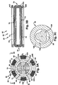
Figs. 3A and 3B , in one particular embodiment of thepump 20, themotor 50 has a four (4) pole, three (3) coil configuration. As shown inFig. 3A , therotor 54 includes aback iron 76 having a cross-shaped cross section that defines recesses having perpendicularly oriented rectangular surfaces in which thepermanent magnets 60 are received and supported. In the four pole configuration, therotor 54 includes fourpermanent magnets 60 spaced equally about theshaft 42. As shown inFig. 3A , therotor 54 has an overall cylindrical configuration. - Referring to
Figs. 3A and 3B , thestator 52 includes astator core 64 and three coils 62, identified individually at 62A, 62B, and 62C, spaced equally about thestator core 64. Thestator core 64 is configured such that the three-phase coils 62 have an elongated configuration withstraight sections 70 that extend axially alongslots 72 in the stator core and end turns 74 at opposite ends of the slots. In this configuration, the end turns 74 of different phase coils 62 do not wrap around or pass over end turns of other phases. - Referring to
Fig. 3A , thestator 52 is an ironless stator, i.e., thestator core 64 is constructed of a low magnetic permeability, non-ferrous material, such as stainless steel, titanium, copper, ceramics, polymeric materials, composite materials, or a combination of these materials. The ironless stator configuration of themotor 50 helps minimize side pull in themotor 50, i.e., the magnetic attraction between therotor 54 andstator 52, which may help reduce the size and stiffness of magnetic radial bearings required to overcome side pull in themotor 50. - Referring to
Fig. 2A , thepump 20 also includesradial bearings 100 that help support theshaft 42 andimpeller 40 for rotation about theaxis 44. In the illustrated embodiment, theradial bearings 100 include a frontradial bearing 102 and a rearradial bearing 104 positioned adjacent opposite ends of themotor 50. Theradial bearings 100 are permanent magnet bearings that utilize permanent magnets, such as NdFeB magnets. Eachradial bearing 100 comprises a plurality of ring-shapedstator magnets 106 and a plurality of ring-shapedrotor magnets 108. In the embodiment ofFig. 2A , the frontradial bearing 102 and rearradial bearing 104 each include tenstator magnets 106 and tenrotor magnets 108. Theradial bearings 100 could have any desired number of stator and rotor magnets. The implementation of the permanentmagnet radial bearings 100 helps eliminate the need for a seal, as is required with conventional mechanical radial bearings. - From the description thus far, it will be appreciated that the
pump 20 includes arotor assembly 120 and astator assembly 122. Therotor assembly 120 includes theimpeller 40,shaft 42,motor magnets 60, backiron 76, radialbearing rotor magnets 108 and any encasing material used to coat or otherwise protect the pump. Thestator assembly 122 includes thehousing 22,inflow stator 46,motor stator core 64, motor stator windings 62, and the radialbearing stator magnets 106 and any encasing material. Themotor 50 imparts rotation of therotor assembly 120 relative to thestator assembly 122. Theradial bearings 100 support therotor assembly 120 for rotation relative to thestator assembly 122. - A
radial motor gap 34 of themotor portion 50 is defined between therotor assembly 120 andstator assembly 122. As shown inFig. 3A , themotor gap 34 has a an annular configuration defined by the spaced cylindrical surfaces of therotor assembly 120 andstator assembly 122. As shown inFig. 3C , however, in an alternative configuration of themotor portion 50, the surface of therotor assembly 120 that helps define themotor gap 34 may comprise aportion 124 may have a non-cylindrical configuration. The non-cylindrical, curved configuration of thesurface 124 can help contribute to the fluid dynamic stability of the flow pattern in themotor gap 34. - The
pump 20 also includes mechanical axial or thrustbearings 140. Theaxial bearings 140 include front and rearaxial bearings rotor assembly 120, that help support therotor assembly 120 for rotation relative to thestator assembly 122. The frontaxial bearing 142 comprises a convex roundedterminal end portion 150 of theimpeller 40 and amating surface 152 of theinlet stator 46. Thesurface 152 acts as a front stop that helps control or limit forward axial movement and the axial position of therotor assembly 120 relative to thestator assembly 122. The rearaxial bearing 142 comprises a convex roundedterminal end portion 154 of therotor assembly 120 and amating surface 156 on thestator assembly 122. Thesurface 156 acts as a rear stop that helps control or limit rearward axial movement and the axial position of therotor assembly 120 relative to thestator assembly 122. - Mating or engaging surfaces of the front and rear
axial bearings rotor assembly 120, i.e., theportions stator assembly 122, i.e., theportions rotor assembly 120, i.e., theportions stator assembly 122, i.e., theportions - The
pump 20 is constructed such that parts that come into contact with blood are made of a biocompatible material. Themotor magnets 60, backiron 76, and radialbearing rotor magnets 108 are encased or otherwise covered or coated on theshaft 42 by abiocompatible material 110. Examples of such materials are titanium and stainless steel. Themotor stator 52, i.e., thestator core 64 and windings 62, and the radialbearing stator magnets 106 are also encased or otherwise covered or coated on thehousing 22 by abiocompatible material 112. Further, theimpeller 40 andinflow stator 46 are constructed, encased, or otherwise covered or coated with a biocompatible material. For example, theimpeller 40 andinflow stator 46 may be constructed of titanium or molded from a biocompatible polymeric material. - Referring to
Fig. 2A , during operation, blood enters thepump 20 axially at theinlet 24, is turned in theimpeller 40, exits the pump at an intermediate angle through theoutlets 26, and flows along the outside diameter of the pump. The flow through theoutlet 26 is thus a mixed flow having both axial and radial components. The primary flow of thepump 20 is thus placed outside thepump 20 instead of through themotor gap 34, which allows the motor gap to be sized without having to consider primary flow requirements through motor gap. This allows thepump 20 to have a small package size while maintaining a motor gap sufficiently large to provide low blood shear. - Also, during operation of the
pump 20, some blood flows into themotor gap 34 through thewash flow port 28. This wash flow washes exposed parts of thepump 20/motor 50 to help prevent deposition and also cools themotor gap 34 before returning to theimpeller 40 and being pumped through theoutlets 26. The wash flow direction is from rear to front, i.e., from thewash flow port 28 to theimpeller 40, due to the pressure rise of the pump. The wash flow may be directed to a midpoint on theimpeller 40 to help improve wash flow. - The
inlet stator 46 may have a vane configuration with a curvature reversed from that of the vanes of theimpeller 40. This helps produce a reverse pre-swirl in the inflow blood, i.e., a swirl in the blood in a direction opposite the rotation of theimpeller 40. Testing has shown that a pre-swirl created in the inflow blood by theinlet stator 46 helps improve the performance characteristics of thepump 20. -
Figs. 11A 11F illustrate selected performance characteristics for a pump configured with the reversedcurvature inlet stator 46 of the present invention versus a pump configured with a conventional non-curved or straight inlet stator. - In the tests used to gather the data shown in
Figs. 11A-11F , the test pump was operated at a nominal speed of 60,000 RPM. To perform the tests, the pump was operated at this nominal speed pumping a fluid having a composition that simulates blood. An outlet conduit connected to the pump was clamped to restrict outlet flow from the pump. The pump was then operated at the nominal speed, the clamp was systematically opened to predefined positions, and data readings were taken at each position to gather the data points inFigs. 11A-11F . Thus, inFigs. 11A-11F , data point pairs for the reverse curved and straight inlet vane configurations correspond to these predefined clamp positions. For example, inFigs. 11A-11F , the data points on the far right ends of the curves correspond to the last of the predefined clamp positions. Going backward or to the left inFigs. 11A-11F , the next-to-last data points correspond to the next-to-last predefined clamp position, and so on. For purposes of this description, a flow of three (3) liters per minute (LPM) at a 90 mmHg pressure rise across the pump are used as nominal or baseline performance characteristics for purposes of comparing the different inlet stator configurations. -
Fig. 11A illustrates stage pressure rise versus flow characteristics for a pump fit with acurved inlet stator 46 at the line indicated at 400 versus a pump fit with a conventional or non-curved inlet stator at the line indicated at 402. The stage pressure rise is the inlet pressure measured immediately before the stator vane within the shroud diameter, subtracted from the outlet pressure measured in the outlet chamber representative of the aorta. -
Fig. 11B illustrates adjusted stage pressure rise versus flow characteristics for a pump fit with acurved inlet stator 46 at the line indicated at 404 versus a pump fit with a conventional or non-curved inlet stator at the line indicated at 406. For comparison, the non-adjusted values fromFig. 11A are included inFig. 11B at 400 and 402. The adjusted stage pressure rise is the estimated pressure just outside the pump inlet subtracted from the outlet pressure measured in the outlet chamber representative of the aorta. The estimated pressure outside the pump inlet is calculated by subtracting reentrant flow losses due to pump insertion into a larger cavity from the measured inlet pressure. - Referring to
Figs. 11A and11B , it can be seen that, other conditions being equal, the pump outfitted with the reversed curved vane inlet stator is capable of achieving the 3 LPM flow at a pressure rise far in excess of the nominal value of 90 mmHg. In comparison, in the same conditions, the straight vane inlet stator falls to meet the 3 LPM flow. -
Fig. 11C illustrates adjusted motor current versus flow characteristics for a pump fit with acurved inlet stator 46 at the line indicated at 410 versus a pump fit with a conventional or non-curved inlet stator at the line indicated at 412. The adjusted motor current is the free running speed current subtracted from the recorded motor current. -
Fig. 11D illustrates estimated motor torque versus flow characteristics for a pump fit with acurved inlet stator 46 at the line indicated at 414 versus a pump fit with a conventional or non-curved inlet stator at the line indicated at 416. The adjusted motor torque is the adjusted motor power divided by pump speed. Adjusted motor power is the adjusted motor current multiplied by the supply voltage. -
Fig. 11E illustrates stage efficiency versus flow characteristics for a pump fit with acurved inlet stator 46 at the line indicated at 420 versus a pump fit with a conventional or non-curved inlet stator at the line indicated at 422. The stage efficiency is the non-adjusted hydraulic power divided by the adjusted motor power. -
Fig. 11F illustrates adjusted stage efficiency versus flow characteristics for a pump fit with acurved inlet stator 46 at the line indicated at 424 versus a pump fit with a conventional or non-curved inlet stator at the line indicated at 426. For comparison, the non-adjusted values fromFig. 11E are included inFig. 11B at 420 and 422. The adjusted stage efficiency is the adjusted hydraulic power divided by the adjusted motor power. The adjusted hydraulic power is the adjusted stage differential pressure rise multiplied by flow. The adjusted stage differential pressure is determined by subtracting reentrant flow losses due to pump insertion into a larger cavity from measured inlet pressure. Non-adjusted stage efficiency takes into account only the adjusted motor power. - As shown in
Figs. 11C-11F , the reversed curved vane inlet stator had higher current and torque ratings for corresponding conditions and also proved to have better efficiency while pumping at 3 LPM. - From the data of
Figs. 11A-11F , it will be appreciated that the reversed curve inlet vane configuration improves the overall performance of the pump in comparison with a conventional straight vane inlet vane configuration. Thus, at the same speed, a pump fitted with the reversed curve inlet vanes will have a higher output flow. Similarly, to achieve the same output, the pump fitted with the reversed curve inlet vanes will operate at a lower speed. Because, of this, blood shear and resulting thrombosis formation can be reduced. This may also help reduce pump power consumption and extend battery life. - Referring to
Fig. 2E , to help further the performance of thepump 20, the pump may include anoutlet stator 88 in addition to theinlet stator 46. Theoutlet stator 88 is constructed in a manner and with materials similar or identical to those described above in regard to theinlet stator 46. Theoutlet stator 88 turns the flow from theimpeller 40 and helps decelerate the flow efficiently and direct the flow through thepump outlet 26. As shown inFig. 2E , theblades 90 of theinlet stator 46 andoutlet stator 88 have a variable thickness from leading edge to trailing edge. This generally tapered shape can be tailored to help lower drag and thereby reduce pressure drop. - Referring to
Figs. 2B and 2C , theimpeller 40 may include ashroud 48 that helps to further improve the pump performance. Theshroud 48 has a generally cylindrical configuration and may be formed as a single piece of material with theimpeller 40 or may be formed separately and subsequently attached to the impeller. Theshroud 48 adds damping which helps stabilize the dynamics of theimpeller 40 and/orrotor assembly 120. - Referring to
Figs. 2B-2D , theimpeller 40 includes ahub 82 and a plurality ofimpeller blades 80 that project outwardly from the hub. Theblades 80 project from thehub 82 in a curved or curvilinear manner, as best shown inFigs. 2C and 2D . Referring toFig. 2D , theblades 80 each have a curved leading edge 84. The curve of the leading edge 84 is configured such that the blade angle varies from thehub 82 to thetip 86 of the blade. As illustrated at α and β inFig. 2D , the blade angle at locations on theblades 80 increase as the location moves from thehub 82 toward thetip 86. This helps compensate for the fact that, as the diameter of theimpeller 40 increases, the local blade speed increases. Varying the blade angle at theleading edge 86 helps to better match the flow angle with the blade angle. - Referring to
Figs. 4A and 4B , theradial bearings 100 operate on a repulsive force principle. Each pair of permanent magnet (PM) rings 106 and 108 has north and south poles aligned in the radial direction. In operation, theradial bearings 100 help overcome the side pull of themotor 50 and maintain therotor assembly 120 suspended relative to thestator assembly 122. Theradial bearings 100 also have an axial stiffness that, in combination with hydraulic forces, helps determine the position of therotor assembly 120 relative to thestator assembly 122. To increase the bearing stiffness, the neighboring PM stator rings 106 and rotor rings 108 are placed in opposing polarity, i.e., north-to-north and south-to-south. The non-ferromagnetic construction of the pump components adjacent theradial bearings 100 helps maintain the magnetic flux paths of themagnets pump 20. ThePM stator magnets 106 may extend 360° about therotor assembly 120. Alternatively, one or more of thePM stator magnets 106 may extend less than 360° about therotor assembly 120. This may help produce a net magnetic force that helps stabilize the submergedrotor assembly 120 during use. -
Figs. 4A and 4B illustrate an unstable equilibrium condition and an axially offset condition, respectively, of theradial bearings 100. Referring toFig. 4A , in the unstable equilibrium condition of theradial bearings 100, the magnetic poles of therotor magnets 108 andstator magnets 106 are axially aligned with each other. This is the desired condition of theradial bearings 100 during operation of thepump 20 because, when the bearings are in this position, therotor assembly 120 is in a position in which theaxial bearings 140 are not loaded. The magnetic flux paths resulting from this arrangement are indicated generally by the arrows in therotor magnets 108 andstator magnets 106. In this axially aligned position, the flux paths are aligned and the attractive/repulsive forces of themagnets stator assembly 122 androtor assembly 120 are radial in nature, as shown by the arrows identified at 170 inFig. 4A . - Referring to
Fig. 4B , in the axially offset condition of theradial bearings 100, the magnetic poles of therotor magnets 108 andstator magnets 106 are offset from each other along the axis ofrotation 44. This distance may be relatively small (e.g., .0002-.002 in.). This is the pre-loaded, axially offset condition prior to operation of thepump 20. The magnetic flux paths resulting from this arrangement are indicated generally by the arrows in therotor magnets 108 andstator magnets 106. In this axially offset position, the flux paths are misaligned and the attractive/repulsive forces of themagnets stator assembly 122 androtor assembly 120 have radial components, as shown by the arrows identified at 172 inFig. 4B , and axial components, as shown by the arrows identified at 174 inFig. 4B . - According to the present invention, the
pump 20 is constructed to produce a net axial force that urges therotor assembly 120 to move axially relative to thestator assembly 122 to the axially offset condition ofFig. 4B . To achieve this, therear stop 156 of the rearaxial bearing 144 and thefront stop 152 of the frontaxial bearing 142 are moved rearward from the positions that would maintain theradial bearings 100 at the unstable equilibrium point. As a result, when thepump 20 is at rest, therotor assembly 120 moves rearward against therear stop 156 under the net axial pull of theradial bearing magnets Fig. 4B . - According to the present invention, the thrust of energy transfer to the fluid by the
impeller 40 and the static pressure gradient front to back on therotor assembly 120 produce hydrodynamic forces that counteract the net axial force of the radial bearing misalignment and help move themagnets Fig. 4A . In operation of thepump 20, fluctuations in applied load, such as those resulting from the natural heart beat of the patient, result in a cyclical front-to-back oscillation of therotor assembly 120 relative to thestator assembly 122. This helps cycle the loads on theaxial bearings 140, which helps reduce friction and heat in the bearings and also helps produce a cyclical washing of the bearings. As a result, these cyclical loads help prevent thrombosis formation in thepump 20 by permitting cyclical washing at the front andrear stops - According to the present invention, the
front stop 152, therear stop 156, or both, may be configured with features that help create axial forces that help minimize or eliminate contact forces when therotor assembly 120 comes close to the contact point Two such features are illustrated inFigs. 2F-2H. Figs. 2F-2H illustrate by way of example therear stop point 156. It will be appreciated, however, that the features ofFigs. 2F-2H could be implemented in therear stop point 156, thefront stop point 152, or both. - Referring to
Figs. 2F-2H , thestop point 156 includes a permanent magnetaxial bearing 160 that exerts an axial force on therotor assembly 120. The force exerted on therotor assembly 120 by thebearing 160 opposes axial forces placed on the rotor assembly by theradial bearings 100 and helps eliminate occasional mechanical contact at thestop point 156. Thestop point 156 also includes surface profiles, such asrecesses 162. As shown inFigs. 2G and 2H , the surface profiles 162 have a generally concave curved configuration and are recessed into the surface of thestop point 156. Theprofiles 162 help generate hydrodynamic lifting forces that help minimize or eliminate contact forces when therotor 120 comes very close to thestop point 156. These hydrodynamic forces help counteract the residuals from the summing of the other axial forces acting on therotor 120. - The
pump 20 may be configured for a number of different implementations, including intravascular and intracorporeal extravascular implementations, as appropriate for patient size. Intravascular implementations may be used for larger patients, such as larger pediatric patients through adolescence and adulthood. Intracorporeal extravascular implementations may be used for smaller patients, such as neonatal and very young pediatric patients. Thepump 20 illustrated in the embodiment ofFigs. 1-3 is configured for intravascular implementations. Examples of these intravascular implementations are shown inFigs. 5A-5C . - Referring to
Fig. 5A , thepump 20 is shown in an intravascular implementation as a right ventricular assist device (RVAD). In the RVAD implementation, thepump 20 is inserted into theheart 200 through anincision 202 in thepulmonary artery 206 at the intersection of thepulmonary trunk 204 and the pulmonary artery. Thepump 20 is positioned with theinlet 24 extending through the pulmonarysemilunar valve 212 into theright ventricle 210 and theoutlet 26 positioned in thepulmonary trunk 204. In operation, thepump 20 operates as described above to assist theright ventricle 210 in pumping blood to thepulmonary artery 206. - Referring to
Fig. 5B , thepump 20 is shown in an intravascular implementation as a left ventricular assist device (LVAD). In the LVAD implementation, thepump 20 is inserted into theheart 200 through anincision 220 in theaorta 222. Thepump 20 is positioned with theinlet 24 extending through the aorticsemilunar valve 226 into theleft ventricle 224 and theoutlet 26 positioned in theaorta 222. In operation, thepump 20 operates as described above to assist theleft ventricle 224 in pumping blood to theaorta 222. - Referring to
Figs. 5A-5C , thepump 20 is fitted with aguide wire 230 that helps direct the pump into the desired position in theheart 200. Theguide wire 230 extends through a sheath or cover 232 of thepower cable 14 of thepump 20, exiting through an opening 234 adjacent or near the location where the cable enters the pump. Thesheath 232 includes a flap 236 that covers and closes the opening 234 when theguide wire 230 is removed. The guide wire may be constructed of a suitable material, such as stainless steel or titanium, selected to exhibit a desired combination of physical properties, such as strength and ductility, that allow the guide wire to be deformable to a desired shape and capable of maintaining the desired shape. - Referring to
Figs. 5A and5B , theguide wire 230 and pump 20 are inserted into theheart 200 through theincisions guide wire 230 may be advanced forward of thepump 20 and guided to the desired location in the organ, i.e., theright ventricle 210 orleft ventricle 224. Thepump 20 can then be delivered to the desired location using the stiffenedguide wire 230 to maneuver and guide placement of the pump. The position of thepump 20 can then be adjusted by sliding thesheath 232 of thepower cable 14 over theguide wire 230. - Referring to
Fig. 5D , twopumps 20 are shown in an intravascular implementation as bi-ventricular assist devices (BVAD). Essentially, the BVAD implementation incorporates twopumps 20 arranged in the RVAD and an LVAD implementations described above inFigs. 5A and5B . InFig. 5D , theguide wire 230 ofFigs. 5A-5C is not shown for purposes of illustrating thepumps 20 with out this feature. Theguide wire 230 ofFigs, 5A-5C is suited for use in the BVAD implementation ofFig. 5D . Thus, in the BVAD implementation, an RVAD pump 20R is inserted through anincision 202 in thepulmonary artery 206 and is oriented with theinlet 24 positioned in theright ventricle 210 and theoutlet 26 positioned in thepulmonary trunk 204. An LVAD pump 20L is inserted through anincision 220 in theaorta 222 and is oriented with theinlet 24 positioned in theleft ventricle 224 and theoutlet 26 positioned in theaorta 222. In operation, the RVAD pump 20R assists theright ventricle 210 in pumping blood to thepulmonary artery 206 and the LVAD pump 20L assists theleft ventricle 224 in pumping blood to theaorta 222. - A second embodiment of the present invention is illustrated in
Fig. 6 . The second embodiment of the invention is similar to the first embodiment of the invention illustrated inFigs. 1-5D . Accordingly, numerals similar to those ofFigs. 1-5D will be utilized inFig. 6 to identify similar components, the suffix letter "a" being associated with the numerals ofFig. 6 to avoid confusion. According to the second embodiment, thepump 20a is configured for intracorporeal extravascular RVAD, LVAD, or BVAD implementations. To accomplish this, thepump 20a of the second embodiment includes an attached catheter or cannula that facilitates insertion in the heart and a catherter or graft to facilitate connection to the vasculature. The catheter or cannula is axially deformable, radially non-collapsible, and impermeable under the physiological and biological conditions associated with the blood pump usages described herein. - Referring to
Fig. 6 , thepump 20a includes apump head housing 250 configured to accommodate an inlet catheter orcannula 252 and an outlet catheter orcannula 252. As shown inFig. 6 , thepump 20a also includes animpeller 260, accommodated in thepump housing 250, that has a configuration varied from that of the first embodiment. Components other than thepump head housing 250 and the impeller 260 (e.g., theinlet stator 46a,motor 50a,radial bearings 100a andaxial bearings 140a) may be similar or identical to that shown and described in conjunction with the first embodiment ofFigs. 1-5D . - The
pump head housing 250 includes aninlet portion 270 connectable with theinlet cannula 252 and anoutlet portion 274 connectable with theoutlet cannula 254. Theinlet portion 270 may include means 272, such as ribs on an outer surface of the inlet portion, that facilitate a secure and reliable connection between the inlet portion and theinlet cannula 252. Likewise, theoutlet portion 274 may include means 276, such as ribs on an outer surface of the outlet portion, that facilitate a secure and reliable connection between the outlet portion and theoutlet cannula 254. This connection may be facilitated, for example, by a wire loop retainer or a threaded clamp retainer. - The configuration of the
pump head housing 250 of the second embodiment helps facilitate extravascular implementations of thepump 20a. More particularly, thepump head housing 250 helps facilitate discharging blood along the outside diameter of the motor/bearinghousing 22a into theoutlet cannula 254. The configuration ofFig. 6 permits wash flow in themotor gap 34a through thewash flow ports 28a under the influence of arterial pressure. As an additional feature of the embodiment ofFig. 6 , the primary flow, being contained within theoutlet cannula 254 next to themotor 50a andmotor housing 22a, may also have some enhanced cooling effects on the motor. Since the primary flow of thepump 20a is outside the pump rather than through themotor gap 34a, the motor gap can be kept at a minimum size, which helps reduce the overall diameter and size of the pump. -
Figs. 7A-7C illustrate intracorporeal extravascular implementations of thepump 20a ofFig. 6 . Referring toFig. 7A , thepump 20a is shown in an intracorporeal extravascular RVAD implementation. In this RVAD implementation, thepump 20a is implanted in the patient next to theheart 200a. Theoutlet cannula 254 is connected viaincision 202a to thepulmonary artery 206a at the intersection of thepulmonary trunk 204a and the pulmonary artery. Theinlet cannula 252 is connected viaincision 282 to theright atrium 280 or, alternatively, theright ventricle 210a. In operation, thepump 20a operates as described above to assist theright ventricle 210a by pumping blood from theright atrium 280 through theinlet cannula 252 to thepulmonary artery 206a via theoutlet cannula 254. - Referring to
Fig. 7B , thepump 20a is shown in an intracorporeal extravascular LVAD implementation. In this LVAD implementation, thepump 20a is implanted in the patient next to theheart 200a. Theoutlet cannula 254 is connected viaincision 220a to theaorta 222a. Theinlet cannula 252 is connected viaincision 286 to the apex 284 of theleft ventricle 224a or, alternatively, the left atrium. In operation, thepump 20a operates as described above to assist theleft ventricle 224a by pumping blood from the left ventricle through theinlet cannula 252 to theaorta 222a via theoutlet cannula 254. - Referring to
Fig. 7C , twopumps 20a are shown in an intracorporeal extravascular implementation as bi-ventricular assist devices (BVAD). Essentially, the BVAD implementation incorporates twopumps 20a arranged in the RVAD and an LVAD implementations described above inFigs. 7A and7B . An RVAD pump 20Ra is implanted in the patient next to theheart 200a. Theoutlet cannula 254R is connected viaincision 202a to thepulmonary artery 206a and theinlet cannula 252R is connected viaincision 282 to theright atrium 280 or, alternatively, the right ventricle. An LVAD pump 20La is implanted in the patient next to theheart 200a. Theoutlet cannula 254L is connected viaincision 220a to theaorta 222a and theinlet cannula 252L is connected viaincision 286 to the apex 284 of theleft ventricle 224a or, alternatively, the left atrium. In operation, the RVAD pump 20Ra assists theright ventricle 210a by pumping blood from theright atrium 280 through theinlet cannula 252R to thepulmonary artery 206a via theoutlet cannula 254R. In operation, the LVAD pump 20La assists theleft ventricle 224a by pumping blood from the left ventricle through theinlet cannula 252L to theaorta 222a via theoutlet cannula 254L. - A third embodiment of the present invention is illustrated in
Figs. 8A-9 . The third embodiment of the invention is similar to the first embodiment of the invention illustrated inFigs. 1-5D . Accordingly, numerals similar to those ofFigs. 1-5D will be utilized inFigs. 8A-9 to identify similar components, the suffix letter "b" being associated with the numerals ofFigs. 8A-9 to avoid confusion. - According to the third embodiment, the
pump 20b is fit with anoutflow sheath 300 for directing the primary mixed flow along the outside of the pump. Theoutflow sheath 300 has a flexible construction that allows the sheath to be wrapped around anouter surface 302 of thepump 20b during implantation. This is shown in dashed lines at 300' inFigs. 8A and8B . During operation of thepump 20b, the flow expands and unwraps thesheath 300 to the position shown in solid lines at 300 inFigs. 8A-9 . This allows the flow to pass through aradial space 304 defined between thepump 20b and thesheath 300. As shown inFigs. 8A and8B , thesheath 300 may include means 320, such as wire bands or a helical coil, that helps limit expansion of the sheath to a desired diameter. The means 320 could, for example, be molded or extruded with thesheath 300 or bonded to the sheath. - Referring to
Fig. 8B , in an alternative configuration, theoutflow sheath 300 has anend portion 310 connected with thepower cable 14b of thepump 20b. This helps resist migration of thesheath 30 back along theouter surface 302 of thepump 20b. Theend portion 310 is connected to thepower cable 14b bymeans 312, such as a clamp. Because thesheath 300 is clamped to thepower cable 14b,outlet flow openings 314 are formed in thesheath 300. - The
sheath 300 allows for reducing the overall size of thepump 20b. For reference, referring back to the embodiment ofFigs. 5A-5D , those skilled in the art will appreciate that, for intravascular implementations of a pump that is not fit with asheath 300, the pump extends through the heart valve and is positioned with the inlet and outlet positioned on opposite sides of the valve. For example, in an LVAD implementation, the pump extends through the heart valve with the inlet positioned in the left ventricle and the outlet positioned in the aorta. As another example, in an RVAD implementation, the pump extends through the heart valve with the inlet positioned in the right ventricle and the outlet positioned in the pulmonary trunk. As shown inFigs. 5A-5D , to achieve these extents, the pump has a configuration in which the inlet is extended to reach into the heart chamber while the outlet is positioned on the opposite side of the heart valve. Those skilled in the art, however, will appreciate that this may result in an unwanted pressure drop on the inlet side of the pump. - Referring to
Fig. 9 , according to the present invention, thesheath 300 functions to extend the outlet of thepump 20b, which eliminates the need to extend the inlet.Fig. 9 illustrates an implementation of thepump 20b ofFig. 8A . Those skilled in the art, however, will appreciate that the pump ofFig. 8B may also be used in the implementation ofFig. 9 . In the LVAD implementation shown inFig. 9 , theinlet 24b andoutlet 26b of thepump 20b are positioned in the heart chamber, i.e., theleft ventricle 224b. Thesheath 300, however, extends through theheart valve 226b into theaorta 222b and thereby effectively places the outlet in the aorta. It will be appreciated that, using this technique, the need for an inlet extension, and any resulting pressure drop, can be eliminated. - The materials used to construct the various components of the
pump 20 are selected to provide a high degree of biocompatibility, corrosion resistance, and manufacturability. For example, materials such as titanium and stainless steel may used to achieve these properties. For performance reasons, the materials of themotor 50 andradial bearings 100 include items of poor corrosion resistance (e.g., copper windings and NdFeB magnets). These materials are dehydrated, plated as appropriate, and hermetically sealed within titanium enclosures. Blood contacting surfaces may be coated with a low-friction, wear resistant material, such as Teflon® or a diamond-like carbon material, to help achieve high blood compatibility and for wear resistance at the axial touch points. Infection resisting coatings may also be used to cover the exterior of the pump in order to resist bacterial colonization and growth around the pump within a tissue pocket. - The
pump 20 also incorporates features that help provide high thrombus resistance without anticoagulation. One such feature is that all surfaces are continuously washed with flowing blood. There are no dead end spaces or crevice-like geometries. The back and forth oscillation of the rotor helps ensure that the blood contacting surfaces inside the pump, including the front and rear stop points 152 an 156, are washed. Also, most surfaces are slightly heated, which helps inhibit platelet aggregation. Further, the Teflon® and diamond-like carbon coatings applied to various pump surfaces may also help prevent coagulation. Another coating that may be used to help prevent coagulation is a synthetic cell membrane material. - The
pump 20 may also include provisions for monitoring motor winding temperatures. Increased winding temperatures may, for example, be indicative of insufficient wash flow, which may result in damage to the blood or tissue. The temperature may be measured using a thermocouple, which requires the addition of hardware and wiring. Alternatively, according to the present invention, winding temperatures may be monitored by measuring the resistance in the motor windings 62 between commutations of the motor phases. The measured resistance can be used to detect increasing temperatures in the motor windings 62. Since the windings are electrically connected to theECU 12 via thecable 14, these measurements may be implemented through reconfiguring the controller without reconfiguring thepump 20. - The
pump 20 further incorporates features that help resist infection. There are at least three areas in which the risk of infection is of heightened concern: pump infection by bacteremia, pocket infections around implanted hardware, and driveline infections around percutaneous lines. By design, thepump 20 has no infusion or monitoring lines that could provide a contamination pathway directly from the environment to the blood stream. Thepump 20 is implanted, which minimizes the number and size of skin penetrations, as well as potential for trauma to these sites. A single, small diameter, very low stiffness wire exits the skin, which minimizes chronic trauma to the site and facilitates healing around the wire surface, which is textured to encourage tissue in-growth. The surface area of the implantedpump 20 body is extremely small, limiting the potential bacterial load that could be carried into a skin pocket. The pump housing may be Teflon® coated, which may help limit bacterial colonization. - The construction of the
pumps 20 , 20A and 20B disclosed herein have small package sizes in comparison with other implantable VADs. This allows for implementation of thepump 20 in the various intravascular and intercorporeal extravascular LVAD, RVAD, and BVAD scenarios described above. The small package size of thepump 20 is made possible by a variety of factors. One such factor is that the primary flow of thepump 20 being placed outside the pump. Another factor is that thepump 20, operating at high RPM (up to 60,000 RPM or more), is able to produce a relatively high output from a relatively small displacement volume. Example configurations illustrating small package size characteristics of thepumps 20 and 20A are set forth in Table 1:Table 1 Intravascular Pump ( Fig. 2A )Intracorporeal Extravascular Pump ( Figs. 6 ,8A ,8B )Diameter, mm 7 11 Length, mm 60 60 Displaced Volwne, ml 2.3 4 Pump Priming Volume, ml 0.55 2.2 Blood Contacting Surface Area, cm2 15.8 33.5 Weight, grams 8.6 10.6 Figs. 10A and10B , even with the small package sizes shown in Table 1, the intravascular pump (seeFig. 2A ) and the intracorporeal pump (seeFig. 6 ) are easily capable of operating at or around the nominal performance ratings for flow (3 LPM) and pressure (90 mmHg). - From the above description of the invention, those skilled in the art will perceive improvements, changes and modifications. Such improvements, changes and modifications within the skill of the art are intended to be covered by the appended claims.
Claims (13)
- A blood pump comprising:a stator assembly comprising a motor stator, a fluid inlet, and a fluid outlet;a rotor assembly comprising a motor rotor and an impeller rotatable about an axis to move fluid from the inlet to the outlet; anda permanent magnet radial bearing for supporting the rotor assembly for rotation about the axis, the radial bearing comprising:a permanent magnet radial bearing stator fixed to the stator assembly and a permanent magnet radial bearing rotor fixed to the rotor assembly, the radial bearing being configured such that the radial bearing stator magnets and the radial bearing rotor magnets are axially offset from each other when the pump is at rest.
- The blood pump recited in claim 1, wherein the offset of the radial bearing stator magnets and the radial bearing rotor magnets is configured to balance with hydrodynamic forces created by pumping action of the impeller.
- The blood pump recited in claim 1, further comprising front and rear stop points configured to limit an axial range of motion of the rotor assembly relative to the stator assembly in order to maintain the axial offset of the radial bearing stator magnets and the radial bearing rotor magnets.
- The blood pump recited in claim 3, wherein at least one of the front and rear stop points comprises a magnetic axial bearing.
- The blood pump recited in claim 3, wherein the stop points comprises surface profiles configured to generate hydrodynamic lifting forces.
- The blood pump recited in claim 3, wherein the stop points are configured to prevent the radial bearings from statically crossing over an unstable magnetic equilibrium point.
- The blood pump recited in claim 1, wherein the radial bearing stator comprises at least one permanent magnet that extends less than 360 degrees about the stator assembly.
- The blood pump recited in claim 1, wherein:the radial bearing stator comprises a plurality of ring shaped stator magnets arranged next to each other in opposing polarity; andthe radial bearing rotor comprises a plurality of ring shaped rotor magnets arranged next to each other in opposing polarity;the pump being configured such that, during operation, the stator magnets and rotor magnets are positioned with like polarities opposing each other.
- The blood pump of claim 8, wherein the ring shaped rotor and stator magnets include a combination of axially and radially polarized elements.
- The blood pump recited in claim 1, wherein the motor stator comprises an ironless motor stator.
- The blood pump recited in claim 1, wherein the rotor has a 2-pole magnetic geometry.
- The blood pump recited in claim 1, the motor stator further comprising a thin outer shell of magnetic material.
- The blood pump recited in claim 1, wherein a radial motor gap is defined between the between the motor stator and the motor rotor, the pump being configured to direct a primary flow from the fluid inlet to the fluid outlet over an outside diameter of the motor and being configured to direct a wash flow through the motor gap.
Applications Claiming Priority (2)
| Application Number | Priority Date | Filing Date | Title |
|---|---|---|---|
| US68765905P | 2005-06-06 | 2005-06-06 | |
| EP06784606.3A EP1898971B1 (en) | 2005-06-06 | 2006-06-06 | Blood pump |
Related Parent Applications (3)
| Application Number | Title | Priority Date | Filing Date |
|---|---|---|---|
| EP06784606.3 Division | 2006-06-06 | ||
| EP06784606.3A Division-Into EP1898971B1 (en) | 2005-06-06 | 2006-06-06 | Blood pump |
| EP06784606.3A Division EP1898971B1 (en) | 2005-06-06 | 2006-06-06 | Blood pump |
Publications (2)
| Publication Number | Publication Date |
|---|---|
| EP2438937A1 true EP2438937A1 (en) | 2012-04-11 |
| EP2438937B1 EP2438937B1 (en) | 2015-10-28 |
Family
ID=37054580
Family Applications (3)
| Application Number | Title | Priority Date | Filing Date |
|---|---|---|---|
| EP11010004.7A Active EP2438937B1 (en) | 2005-06-06 | 2006-06-06 | Blood pump |
| EP11010003.9A Active EP2438936B1 (en) | 2005-06-06 | 2006-06-06 | Blood pump |
| EP06784606.3A Active EP1898971B1 (en) | 2005-06-06 | 2006-06-06 | Blood pump |
Family Applications After (2)
| Application Number | Title | Priority Date | Filing Date |
|---|---|---|---|
| EP11010003.9A Active EP2438936B1 (en) | 2005-06-06 | 2006-06-06 | Blood pump |
| EP06784606.3A Active EP1898971B1 (en) | 2005-06-06 | 2006-06-06 | Blood pump |
Country Status (5)
| Country | Link |
|---|---|
| US (5) | US8177703B2 (en) |
| EP (3) | EP2438937B1 (en) |
| AU (1) | AU2006255059A1 (en) |
| CA (1) | CA2611313A1 (en) |
| WO (1) | WO2006133209A1 (en) |
Cited By (4)
| Publication number | Priority date | Publication date | Assignee | Title |
|---|---|---|---|---|
| WO2019178173A1 (en) * | 2018-03-14 | 2019-09-19 | The Cleveland Clinic Foundation | Blood pump with magnetically loaded partial arc journal bearings |
| US11754075B2 (en) | 2018-07-10 | 2023-09-12 | Kardion Gmbh | Impeller for an implantable, vascular support system |
| US11804767B2 (en) | 2018-01-24 | 2023-10-31 | Kardion Gmbh | Magnetic coupling element with a magnetic bearing function |
| US11944805B2 (en) | 2020-01-31 | 2024-04-02 | Kardion Gmbh | Pump for delivering a fluid and method of manufacturing a pump |
Families Citing this family (169)
| Publication number | Priority date | Publication date | Assignee | Title |
|---|---|---|---|---|
| AT500427B1 (en) * | 2002-05-29 | 2009-02-15 | Anagnostics Bioanalysis Gmbh | DEVICE FOR ANALYZING INGREDIENTS OF A SAMPLE |
| US8012079B2 (en) | 2004-08-13 | 2011-09-06 | Procyrion, Inc. | Method and apparatus for long-term assisting a left ventricle to pump blood |
| US7393181B2 (en) | 2004-09-17 | 2008-07-01 | The Penn State Research Foundation | Expandable impeller pump |
| WO2006133209A1 (en) * | 2005-06-06 | 2006-12-14 | The Cleveland Clinic Foundation | Blood pump |
| AT502549B1 (en) * | 2005-10-07 | 2007-06-15 | Anagnostics Bioanalysis Gmbh | DEVICE FOR THE ANALYSIS OF LIQUID SAMPLES |
| JP2009530041A (en) | 2006-03-23 | 2009-08-27 | ザ・ペン・ステート・リサーチ・ファンデーション | Cardiac assist device with expandable impeller pump |
| US8079948B2 (en) * | 2007-08-29 | 2011-12-20 | NuCardia, Inc. | Article comprising an impeller |
| US8439859B2 (en) * | 2007-10-08 | 2013-05-14 | Ais Gmbh Aachen Innovative Solutions | Catheter device |
| WO2009091965A1 (en) * | 2008-01-18 | 2009-07-23 | Med Institute, Inc. | Intravascular device attachment system having tubular expandable body |
| EP2194278A1 (en) | 2008-12-05 | 2010-06-09 | ECP Entwicklungsgesellschaft mbH | Fluid pump with a rotor |
| EP2216059A1 (en) | 2009-02-04 | 2010-08-11 | ECP Entwicklungsgesellschaft mbH | Catheter device with a catheter and an actuation device |
| EP2229965A1 (en) | 2009-03-18 | 2010-09-22 | ECP Entwicklungsgesellschaft mbH | Fluid pump with particular form of a rotor blade |
| DE102009014462B4 (en) * | 2009-03-23 | 2019-01-17 | Siemens Healthcare Gmbh | A blood pump, medical device, comprising a blood pump and methods for assisting the placement of a blood pump |
| EP2246078A1 (en) | 2009-04-29 | 2010-11-03 | ECP Entwicklungsgesellschaft mbH | Shaft assembly with a shaft which moves within a fluid-filled casing |
| EP2248544A1 (en) | 2009-05-05 | 2010-11-10 | ECP Entwicklungsgesellschaft mbH | Fluid pump with variable circumference, particularly for medical use |
| US9782527B2 (en) | 2009-05-27 | 2017-10-10 | Tc1 Llc | Monitoring of redundant conductors |
| EP2266640A1 (en) | 2009-06-25 | 2010-12-29 | ECP Entwicklungsgesellschaft mbH | Compressible and expandable turbine blade for a fluid pump |
| CA2769631A1 (en) | 2009-07-01 | 2011-01-06 | The Penn State Research Foundation | Blood pump with expandable cannula |
| EP2282070B1 (en) | 2009-08-06 | 2012-10-17 | ECP Entwicklungsgesellschaft mbH | Catheter device with a coupling device for a drive device |
| EP2298373A1 (en) | 2009-09-22 | 2011-03-23 | ECP Entwicklungsgesellschaft mbH | Fluid pump with at least one turbine blade and a seating device |
| EP2298372A1 (en) | 2009-09-22 | 2011-03-23 | ECP Entwicklungsgesellschaft mbH | Rotor for an axial pump for transporting a fluid |
| EP2298371A1 (en) | 2009-09-22 | 2011-03-23 | ECP Entwicklungsgesellschaft mbH | Function element, in particular fluid pump with a housing and a transport element |
| DK3441616T3 (en) | 2009-09-22 | 2023-05-30 | Ecp Entw Mbh | COMPRESSIBLE ROTOR FOR A FLUID PUMP |
| EP2314331B1 (en) | 2009-10-23 | 2013-12-11 | ECP Entwicklungsgesellschaft mbH | Catheter pump arrangement and flexible shaft arrangement with a cable core |
| EP2314330A1 (en) | 2009-10-23 | 2011-04-27 | ECP Entwicklungsgesellschaft mbH | Flexible shaft arrangement |
| EP2338539A1 (en) | 2009-12-23 | 2011-06-29 | ECP Entwicklungsgesellschaft mbH | Pump device with a detection device |
| EP2338541A1 (en) | 2009-12-23 | 2011-06-29 | ECP Entwicklungsgesellschaft mbH | Radial compressible and expandable rotor for a fluid pump |
| EP2338540A1 (en) | 2009-12-23 | 2011-06-29 | ECP Entwicklungsgesellschaft mbH | Delivery blade for a compressible rotor |
| US8562508B2 (en) | 2009-12-30 | 2013-10-22 | Thoratec Corporation | Mobility-enhancing blood pump system |
| EP2347778A1 (en) | 2010-01-25 | 2011-07-27 | ECP Entwicklungsgesellschaft mbH | Fluid pump with a radially compressible rotor |
| EP2537247A4 (en) * | 2010-02-16 | 2018-01-31 | CircuLite, Inc. | Test controller for a rotary pump |
| EP2363157A1 (en) | 2010-03-05 | 2011-09-07 | ECP Entwicklungsgesellschaft mbH | Device for exerting mechanical force on a medium, in particular fluid pump |
| EP2388029A1 (en) | 2010-05-17 | 2011-11-23 | ECP Entwicklungsgesellschaft mbH | Pump array |
| TW201217010A (en) | 2010-06-22 | 2012-05-01 | Thoratec Corp | Apparatus and method for modifying pressure-flow characteristics of a pump |
| EP2399639A1 (en) | 2010-06-25 | 2011-12-28 | ECP Entwicklungsgesellschaft mbH | System for introducing a pump |
| EP2407187A3 (en) | 2010-07-15 | 2012-06-20 | ECP Entwicklungsgesellschaft mbH | Blood pump for invasive application within the body of a patient |
| EP2407186A1 (en) | 2010-07-15 | 2012-01-18 | ECP Entwicklungsgesellschaft mbH | Rotor for a pump, produced with an initial elastic material |
| EP2407185A1 (en) | 2010-07-15 | 2012-01-18 | ECP Entwicklungsgesellschaft mbH | Radial compressible and expandable rotor for a pump with a turbine blade |
| WO2012012552A1 (en) | 2010-07-22 | 2012-01-26 | Thoratec Corporation | Controlling implanted blood pumps |
| US9091271B2 (en) | 2010-08-20 | 2015-07-28 | Thoratec Corporation | Implantable blood pump |
| EP2422735A1 (en) | 2010-08-27 | 2012-02-29 | ECP Entwicklungsgesellschaft mbH | Implantable blood transportation device, manipulation device and coupling device |
| JP5577506B2 (en) | 2010-09-14 | 2014-08-27 | ソーラテック コーポレイション | Centrifugal pump device |
| AU2011305250B2 (en) | 2010-09-24 | 2014-10-02 | Thoratec Corporation | Generating artificial pulse |
| EP2627366B1 (en) * | 2010-10-13 | 2016-08-31 | Thoratec Corporation | Blood pump |
| US8597170B2 (en) * | 2011-01-05 | 2013-12-03 | Thoratec Corporation | Catheter pump |
| US8485961B2 (en) | 2011-01-05 | 2013-07-16 | Thoratec Corporation | Impeller housing for percutaneous heart pump |
| WO2012094641A2 (en) | 2011-01-06 | 2012-07-12 | Thoratec Corporation | Percutaneous heart pump |
| WO2012094535A2 (en) * | 2011-01-06 | 2012-07-12 | Thoratec Corporation | Percutaneous heart pump |
| EP2497521A1 (en) | 2011-03-10 | 2012-09-12 | ECP Entwicklungsgesellschaft mbH | Push device for axial insertion of a string-shaped, flexible body |
| EP2693609B1 (en) | 2011-03-28 | 2017-05-03 | Thoratec Corporation | Rotation and drive device and centrifugal pump device using same |
| CA2835212A1 (en) * | 2011-05-13 | 2012-11-22 | Heartware, Inc. | Intravascular blood pump and method of implantation |
| US10226558B2 (en) | 2011-05-13 | 2019-03-12 | Mayo Foundation For Medical Education And Research | Cannula apparatus and ventricular assist systems using the cannula apparatus |
| EP2549113B1 (en) * | 2011-07-20 | 2018-10-24 | Levitronix GmbH | Magnetic rotor and rotation pump with a magnetic rotor |
| EP2564771A1 (en) | 2011-09-05 | 2013-03-06 | ECP Entwicklungsgesellschaft mbH | Medicinal product with a functional element for invasive use in the body of a patient |
| US8926492B2 (en) | 2011-10-11 | 2015-01-06 | Ecp Entwicklungsgesellschaft Mbh | Housing for a functional element |
| WO2013056131A1 (en) | 2011-10-13 | 2013-04-18 | Reichenbach Steven H | Pump and method for mixed flow blood pumping |
| KR102109391B1 (en) | 2011-11-28 | 2020-05-13 | 미-바드, 아이엔씨. | Ventricular assist device and method |
| AU2012345572C1 (en) | 2011-12-03 | 2018-05-31 | Indiana University Research And Technology Corporation | Cavopulmonary viscous impeller assist device and method |
| DE102012202411B4 (en) * | 2012-02-16 | 2018-07-05 | Abiomed Europe Gmbh | INTRAVASAL BLOOD PUMP |
| WO2013134319A1 (en) | 2012-03-05 | 2013-09-12 | Justin Aron Callaway | Modular implantable medical pump |
| GB2504176A (en) | 2012-05-14 | 2014-01-22 | Thoratec Corp | Collapsible impeller for catheter pump |
| US9872947B2 (en) * | 2012-05-14 | 2018-01-23 | Tc1 Llc | Sheath system for catheter pump |
| US9327067B2 (en) | 2012-05-14 | 2016-05-03 | Thoratec Corporation | Impeller for catheter pump |
| US9446179B2 (en) | 2012-05-14 | 2016-09-20 | Thoratec Corporation | Distal bearing support |
| US8721517B2 (en) | 2012-05-14 | 2014-05-13 | Thoratec Corporation | Impeller for catheter pump |
| EP4186557A1 (en) | 2012-07-03 | 2023-05-31 | Tc1 Llc | Motor assembly for catheter pump |
| US9421311B2 (en) | 2012-07-03 | 2016-08-23 | Thoratec Corporation | Motor assembly for catheter pump |
| US9358329B2 (en) | 2012-07-03 | 2016-06-07 | Thoratec Corporation | Catheter pump |
| EP2890419B1 (en) | 2012-08-31 | 2019-07-31 | Tc1 Llc | Start-up algorithm for an implantable blood pump |
| US9579436B2 (en) | 2012-08-31 | 2017-02-28 | Thoratec Corporation | Sensor mounting in an implantable blood pump |
| US10857274B2 (en) | 2012-11-06 | 2020-12-08 | Queen Mary University Of London | Mechanical circulatory support device with centrifugal impeller designed for implantation in the descending aorta |
| WO2014085806A1 (en) | 2012-11-30 | 2014-06-05 | The Penn State Research Foundation | Smart tip lvad inlet cannula |
| US9371826B2 (en) | 2013-01-24 | 2016-06-21 | Thoratec Corporation | Impeller position compensation using field oriented control |
| US9556873B2 (en) | 2013-02-27 | 2017-01-31 | Tc1 Llc | Startup sequence for centrifugal pump with levitated impeller |
| US11033728B2 (en) | 2013-03-13 | 2021-06-15 | Tc1 Llc | Fluid handling system |
| EP2968718B1 (en) | 2013-03-13 | 2021-04-21 | Tc1 Llc | Fluid handling system |
| US11077294B2 (en) | 2013-03-13 | 2021-08-03 | Tc1 Llc | Sheath assembly for catheter pump |
| WO2014143593A1 (en) | 2013-03-15 | 2014-09-18 | Thoratec Corporation | Catheter pump assembly including a stator |
| US9308302B2 (en) | 2013-03-15 | 2016-04-12 | Thoratec Corporation | Catheter pump assembly including a stator |
| EP2983732B1 (en) * | 2013-04-08 | 2022-02-23 | Systol Dynamics | Left ventricular cardiac assist pump and methods therefor |
| US10052420B2 (en) | 2013-04-30 | 2018-08-21 | Tc1 Llc | Heart beat identification and pump speed synchronization |
| DE102013208038B4 (en) | 2013-05-02 | 2016-09-08 | Michael Siegenthaler | Catheter-based cardiac assist system |
| US10111994B2 (en) | 2013-05-14 | 2018-10-30 | Heartware, Inc. | Blood pump with separate mixed-flow and axial-flow impeller stages and multi-stage stators |
| DE102013211848A1 (en) | 2013-06-21 | 2014-12-24 | Heraeus Precious Metals Gmbh & Co. Kg | Pump housing made of at least two different sinterable materials |
| DE102013211844A1 (en) | 2013-06-21 | 2014-12-24 | Heraeus Precious Metals Gmbh & Co. Kg | Pump housing made of a magnetic and a non-magnetic material |
| US9474644B2 (en) | 2014-02-07 | 2016-10-25 | Zoll Circulation, Inc. | Heat exchange system for patient temperature control with multiple coolant chambers for multiple heat exchange modalities |
| US10500088B2 (en) | 2014-02-14 | 2019-12-10 | Zoll Circulation, Inc. | Patient heat exchange system with two and only two fluid loops |
| US10792185B2 (en) | 2014-02-14 | 2020-10-06 | Zoll Circulation, Inc. | Fluid cassette with polymeric membranes and integral inlet and outlet tubes for patient heat exchange system |
| US11033424B2 (en) | 2014-02-14 | 2021-06-15 | Zoll Circulation, Inc. | Fluid cassette with tensioned polymeric membranes for patient heat exchange system |
| EP3110468B1 (en) | 2014-02-25 | 2021-11-03 | Kushwaha, Sudhir | Ventricular assist device and method |
| DE102014004121A1 (en) | 2014-03-24 | 2015-09-24 | Heraeus Deutschland GmbH & Co. KG | Pump housing made of at least three different sinterable materials |
| US9744280B2 (en) | 2014-04-15 | 2017-08-29 | Tc1 Llc | Methods for LVAD operation during communication losses |
| WO2015160990A1 (en) | 2014-04-15 | 2015-10-22 | Thoratec Corporation | Catheter pump introducer systems and methods |
| EP3131600B1 (en) | 2014-04-15 | 2021-06-16 | Tc1 Llc | Methods and systems for providing battery feedback to patient |
| WO2015160995A1 (en) | 2014-04-15 | 2015-10-22 | Thoratec Corporation | Ventricular assist devices |
| WO2015160943A1 (en) | 2014-04-15 | 2015-10-22 | Thoratec Corporation | Sensors for catheter pumps |
| WO2015160942A1 (en) | 2014-04-15 | 2015-10-22 | Thoratec Corporation | Catheter pump with off-set motor position |
| WO2015160994A1 (en) | 2014-04-15 | 2015-10-22 | Thoratec Corporation | Methods and systems for upgrading ventricle assist devices |
| WO2015160979A1 (en) | 2014-04-15 | 2015-10-22 | Thoratec Corporation | Catheter pump with access ports |
| CN106456853B (en) | 2014-04-15 | 2019-04-23 | Tc1有限责任公司 | For controlling the method and system of blood pump |
| GB2527059A (en) | 2014-06-10 | 2015-12-16 | Calon Cardio Technology Ltd | Cardiac pump |
| CN104056314A (en) * | 2014-06-20 | 2014-09-24 | 冯森铭 | Implantable mini-type shaftless efficient heat transfer axial blood pump |
| US10449279B2 (en) | 2014-08-18 | 2019-10-22 | Tc1 Llc | Guide features for percutaneous catheter pump |
| US9623161B2 (en) | 2014-08-26 | 2017-04-18 | Tc1 Llc | Blood pump and method of suction detection |
| EP3200846B1 (en) | 2014-10-01 | 2020-01-15 | Heartware, Inc. | Backup controller system with updating |
| US11359620B2 (en) * | 2015-04-01 | 2022-06-14 | Zoll Circulation, Inc. | Heat exchange system for patient temperature control with easy loading high performance peristaltic pump |
| US9784263B2 (en) | 2014-11-06 | 2017-10-10 | Zoll Circulation, Inc. | Heat exchange system for patient temperature control with easy loading high performance peristaltic pump |
| US10724534B2 (en) | 2014-11-26 | 2020-07-28 | Tc1 Llc | Pump and method for mixed flow blood pumping |
| WO2016118777A1 (en) | 2015-01-22 | 2016-07-28 | Thoratec Corporation | Reduced rotational mass motor assembly for catheter pump |
| EP3598986B1 (en) | 2015-01-22 | 2021-02-17 | Tc1 Llc | Motor assembly with heat exchanger for catheter pump |
| WO2016118784A1 (en) | 2015-01-22 | 2016-07-28 | Thoratec Corporation | Attachment mechanisms for motor of catheter pump |
| EP3256183A4 (en) | 2015-02-11 | 2018-09-19 | Tc1 Llc | Heart beat identification and pump speed synchronization |
| US10371152B2 (en) | 2015-02-12 | 2019-08-06 | Tc1 Llc | Alternating pump gaps |
| US10166318B2 (en) | 2015-02-12 | 2019-01-01 | Tc1 Llc | System and method for controlling the position of a levitated rotor |
| US10245361B2 (en) | 2015-02-13 | 2019-04-02 | Tc1 Llc | Impeller suspension mechanism for heart pump |
| US10537465B2 (en) | 2015-03-31 | 2020-01-21 | Zoll Circulation, Inc. | Cold plate design in heat exchanger for intravascular temperature management catheter and/or heat exchange pad |
| US10022265B2 (en) | 2015-04-01 | 2018-07-17 | Zoll Circulation, Inc. | Working fluid cassette with hinged plenum or enclosure for interfacing heat exchanger with intravascular temperature management catheter |
| US9907890B2 (en) | 2015-04-16 | 2018-03-06 | Tc1 Llc | Catheter pump with positioning brace |
| EP3313471A4 (en) | 2015-06-29 | 2019-02-20 | Tc1 Llc | Ventricular assist devices having a hollow rotor and methods of use |
| WO2017015268A1 (en) | 2015-07-20 | 2017-01-26 | Thoratec Corporation | Flow estimation using hall-effect sensors |
| EP3324840A4 (en) | 2015-07-20 | 2019-03-20 | Tc1 Llc | Strain gauge for flow estimation |
| EP3341052B1 (en) * | 2015-08-28 | 2021-09-29 | Crisi Medical Systems, Inc. | Flow sensor system with absorber |
| CA2999986A1 (en) * | 2015-09-25 | 2017-03-30 | Procyrion, Inc. | Non-occluding intravascular blood pump providing reduced hemolysis |
| EP3153191A1 (en) | 2015-10-09 | 2017-04-12 | ECP Entwicklungsgesellschaft mbH | Blood pump |
| US10117983B2 (en) | 2015-11-16 | 2018-11-06 | Tc1 Llc | Pressure/flow characteristic modification of a centrifugal pump in a ventricular assist device |
| US10441693B2 (en) * | 2016-04-01 | 2019-10-15 | Heartware, Inc. | Axial flow blood pump with radially offset rotor |
| AU2016405653B2 (en) * | 2016-05-02 | 2021-05-13 | Star Bp, Inc. | Heart assist device |
| EP3808401A1 (en) * | 2016-07-21 | 2021-04-21 | Tc1 Llc | Gas-filled chamber for catheter pump motor assembly |
| US10857273B2 (en) | 2016-07-21 | 2020-12-08 | Tc1 Llc | Rotary seal for cantilevered rotor pump and methods for axial flow blood pumping |
| US11160970B2 (en) | 2016-07-21 | 2021-11-02 | Tc1 Llc | Fluid seals for catheter pump motor assembly |
| RU2629054C1 (en) * | 2016-08-10 | 2017-08-24 | Федеральное государственное бюджетное учреждение "Национальный исследовательский центр "Курчатовский институт" | Axial pump of auxiliary circulation |
| WO2018031741A1 (en) | 2016-08-12 | 2018-02-15 | Tc1 Llc | Devices and methods for monitoring bearing and seal performance |
| US11524153B2 (en) | 2016-10-03 | 2022-12-13 | Queen Mary University Of London | Mechanical circulatory support device with axial flow turbomachine optimized for heart failure and cardio-renal syndrome by implantation in the descending aorta |
| JP7383476B2 (en) | 2016-10-25 | 2023-11-20 | マジェンタ・メディカル・リミテッド | ventricular assist device |
| RU2637605C1 (en) * | 2016-11-09 | 2017-12-05 | Алексей Васильевич Коротеев | Microaxial pump for circulation maintenance (versions) |
| US11185440B2 (en) | 2017-02-02 | 2021-11-30 | Zoll Circulation, Inc. | Devices, systems and methods for endovascular temperature control |
| US11116657B2 (en) | 2017-02-02 | 2021-09-14 | Zoll Circulation, Inc. | Devices, systems and methods for endovascular temperature control |
| EP3630218A4 (en) * | 2017-06-01 | 2021-05-12 | Queen Mary University of London | Mechanical circulatory support device with centrifugal impeller designed for implantation in the descending aorta |
| EP3634528B1 (en) | 2017-06-07 | 2023-06-07 | Shifamed Holdings, LLC | Intravascular fluid movement devices, systems, and methods of use |
| DE102017210883A1 (en) * | 2017-06-28 | 2019-01-03 | Robert Bosch Gmbh | A rotor assembly for a cardiac assist system and method and apparatus for manufacturing a rotor assembly for a cardiac assist system |
| CN111556763B (en) | 2017-11-13 | 2023-09-01 | 施菲姆德控股有限责任公司 | Intravascular fluid movement device and system |
| CA3088846A1 (en) * | 2018-01-08 | 2019-07-11 | Vadovations, Inc. | Heart assist device |
| US10973967B2 (en) | 2018-01-10 | 2021-04-13 | Tc1 Llc | Bearingless implantable blood pump |
| US10905808B2 (en) | 2018-01-10 | 2021-02-02 | Magenta Medical Ltd. | Drive cable for use with a blood pump |
| EP4039321A1 (en) | 2018-01-10 | 2022-08-10 | Magenta Medical Ltd. | Ventricular assist device |
| EP4085965A1 (en) | 2018-02-01 | 2022-11-09 | Shifamed Holdings, LLC | Intravascular blood pumps and methods of use and manufacture |
| CA3094838A1 (en) | 2018-03-23 | 2019-09-26 | Abiomed Europe Gmbh | Method of manufacturing a blood pump |
| EP3542836A1 (en) * | 2018-03-23 | 2019-09-25 | Abiomed Europe GmbH | Intravascular blood pump with ceramic inner sleeve |
| DK3542837T3 (en) | 2018-03-23 | 2020-09-21 | Abiomed Europe Gmbh | INTRAVASCULAR BLOOD PUMP |
| WO2019195480A1 (en) | 2018-04-04 | 2019-10-10 | Theodosios Korakianitis | Removable mechanical circulatory support for short term use |
| US11690997B2 (en) | 2018-04-06 | 2023-07-04 | Puzzle Medical Devices Inc. | Mammalian body conduit intralumenal device and lumen wall anchor assembly, components thereof and methods of implantation and explanation thereof |
| DE102018208879A1 (en) * | 2018-06-06 | 2020-01-30 | Kardion Gmbh | Method for determining a total fluid volume flow in the area of an implanted, vascular support system |
| CA3109530A1 (en) * | 2018-08-07 | 2020-02-13 | Kardion Gmbh | Bearing device for a cardiac support system, and method for flushing an intermediate space in a bearing device for a cardiac support |
| CN112655142A (en) * | 2018-08-28 | 2021-04-13 | 波士顿科学国际有限公司 | Axial flux motor of percutaneous circulation supporting device |
| CN112689716B (en) | 2018-10-18 | 2023-06-30 | 波士顿科学国际有限公司 | Blood pump shaft bearing |
| US11484698B2 (en) * | 2019-07-09 | 2022-11-01 | Boston Scientific Scimed, Inc. | Circulatory support device |
| WO2020152611A2 (en) | 2019-01-24 | 2020-07-30 | Magenta Medical Ltd | Ventricular assist device |
| US11471683B2 (en) | 2019-01-29 | 2022-10-18 | Synapse Biomedical, Inc. | Systems and methods for treating sleep apnea using neuromodulation |
| JP2020128745A (en) | 2019-02-01 | 2020-08-27 | ホワイト ナイト フルイド ハンドリング インコーポレーテッドWhite Knight Fluid Handling Inc. | Pump having magnet for journaling and magnetically axially positioning rotor thereof, and related method |
| CN113993576A (en) * | 2019-03-26 | 2022-01-28 | 益智医疗器械股份有限公司 | Modular mammalian body implantable fluid flow affecting devices and related methods |
| CN114828942A (en) | 2019-06-28 | 2022-07-29 | 狄奥多西·亚历山大 | Removable mechanical circulation support device for short-term use |
| US11964145B2 (en) | 2019-07-12 | 2024-04-23 | Shifamed Holdings, Llc | Intravascular blood pumps and methods of manufacture and use |
| US11654275B2 (en) | 2019-07-22 | 2023-05-23 | Shifamed Holdings, Llc | Intravascular blood pumps with struts and methods of use and manufacture |
| US11583672B2 (en) * | 2019-08-30 | 2023-02-21 | Boston Scientific Scimed, Inc. | Glass impeller for a blood pump |
| US11724089B2 (en) | 2019-09-25 | 2023-08-15 | Shifamed Holdings, Llc | Intravascular blood pump systems and methods of use and control thereof |
| IL293625A (en) | 2019-12-03 | 2022-08-01 | Procyrion Inc | Blood pumps |
| AU2020403115A1 (en) | 2019-12-13 | 2022-07-14 | Procyrion, Inc. | Support structures for intravascular blood pumps |
| EP3859954A1 (en) * | 2020-01-30 | 2021-08-04 | Maxon International AG | Functionally safe brushless dc electric motor |
| CN115666708A (en) * | 2021-03-17 | 2023-01-31 | 怡忠生命科学有限公司 | Implantable ventricular epitaxy co-pulsation circulation support system with seamless flow guide pipe assembly |
Citations (6)
| Publication number | Priority date | Publication date | Assignee | Title |
|---|---|---|---|---|
| EP0150320A1 (en) * | 1983-11-29 | 1985-08-07 | Fraunhofer-Gesellschaft Zur Förderung Der Angewandten Forschung E.V. | Magnetic bearing |
| US5507629A (en) * | 1994-06-17 | 1996-04-16 | Jarvik; Robert | Artificial hearts with permanent magnet bearings |
| WO1998014225A2 (en) * | 1996-10-04 | 1998-04-09 | United States Surgical Corporation | Circulatory support system |
| US5851174A (en) * | 1996-09-17 | 1998-12-22 | Robert Jarvik | Cardiac support device |
| US20030193252A1 (en) * | 2001-06-14 | 2003-10-16 | Mohawk Innovative Technology, Inc. | Combination magnetic radial and thrust bearing |
| WO2004101029A1 (en) * | 2003-05-13 | 2004-11-25 | Cardianove Inc. | Blood pump with frusto-conical bearing structure |
Family Cites Families (68)
| Publication number | Priority date | Publication date | Assignee | Title |
|---|---|---|---|---|
| US4625712A (en) | 1983-09-28 | 1986-12-02 | Nimbus, Inc. | High-capacity intravascular blood pump utilizing percutaneous access |
| US4704121A (en) | 1983-09-28 | 1987-11-03 | Nimbus, Inc. | Anti-thrombogenic blood pump |
| US4753221A (en) * | 1986-10-22 | 1988-06-28 | Intravascular Surgical Instruments, Inc. | Blood pumping catheter and method of use |
| US4779614A (en) | 1987-04-09 | 1988-10-25 | Nimbus Medical, Inc. | Magnetically suspended rotor axial flow blood pump |
| US4817586A (en) | 1987-11-24 | 1989-04-04 | Nimbus Medical, Inc. | Percutaneous bloom pump with mixed-flow output |
| US4846152A (en) | 1987-11-24 | 1989-07-11 | Nimbus Medical, Inc. | Single-stage axial flow blood pump |
| US4895557A (en) | 1987-12-07 | 1990-01-23 | Nimbus Medical, Inc. | Drive mechanism for powering intravascular blood pumps |
| US4906229A (en) | 1988-05-03 | 1990-03-06 | Nimbus Medical, Inc. | High-frequency transvalvular axisymmetric blood pump |
| US4908012A (en) | 1988-08-08 | 1990-03-13 | Nimbus Medical, Inc. | Chronic ventricular assist system |
| US4957504A (en) | 1988-12-02 | 1990-09-18 | Chardack William M | Implantable blood pump |
| US5211546A (en) | 1990-05-29 | 1993-05-18 | Nu-Tech Industries, Inc. | Axial flow blood pump with hydrodynamically suspended rotor |
| US5112200A (en) | 1990-05-29 | 1992-05-12 | Nu-Tech Industries, Inc. | Hydrodynamically suspended rotor axial flow blood pump |
| EP0543099A3 (en) | 1991-11-19 | 1994-05-25 | Bristol Myers Squibb Co | Implant fixation stem |
| US5227820A (en) | 1992-06-01 | 1993-07-13 | Ctx-Electronics Corporation | Shading device of the LCD projecting plate |
| SE501215C2 (en) | 1992-09-02 | 1994-12-12 | Oeyvind Reitan | catheter Pump |
| US5376114A (en) | 1992-10-30 | 1994-12-27 | Jarvik; Robert | Cannula pumps for temporary cardiac support and methods of their application and use |
| US5393207A (en) | 1993-01-21 | 1995-02-28 | Nimbus, Inc. | Blood pump with disposable rotor assembly |
| US5947892A (en) | 1993-11-10 | 1999-09-07 | Micromed Technology, Inc. | Rotary blood pump |
| US5527159A (en) | 1993-11-10 | 1996-06-18 | The United States Of America As Represented By The Administrator Of The National Aeronautics And Space Administration | Rotary blood pump |
| US5957672A (en) | 1993-11-10 | 1999-09-28 | The United States Of America As Represented By The Administrator Of The National Aeronautics And Space Administration | Blood pump bearing system |
| US5755785A (en) | 1994-08-12 | 1998-05-26 | The University Of South Florida | Sutureless corneal transplantation method |
| US5613935A (en) | 1994-12-16 | 1997-03-25 | Jarvik; Robert | High reliability cardiac assist system |
| US5588812A (en) | 1995-04-19 | 1996-12-31 | Nimbus, Inc. | Implantable electric axial-flow blood pump |
| US5707218A (en) | 1995-04-19 | 1998-01-13 | Nimbus, Inc. | Implantable electric axial-flow blood pump with blood cooled bearing |
| US5938412A (en) | 1995-06-01 | 1999-08-17 | Advanced Bionics, Inc. | Blood pump having rotor with internal bore for fluid flow |
| US5924848A (en) | 1995-06-01 | 1999-07-20 | Advanced Bionics, Inc. | Blood pump having radial vanes with enclosed magnetic drive components |
| EP0764448B1 (en) | 1995-09-22 | 2003-07-30 | United States Surgical Corporation | Cardiac support device |
| US5824070A (en) | 1995-10-30 | 1998-10-20 | Jarvik; Robert | Hybrid flow blood pump |
| US5840070A (en) | 1996-02-20 | 1998-11-24 | Kriton Medical, Inc. | Sealless rotary blood pump |
| DE19613565C1 (en) | 1996-04-04 | 1997-07-24 | Guenter Prof Dr Rau | Intravasal blood pump with drive motor |
| DE19613564C1 (en) * | 1996-04-04 | 1998-01-08 | Guenter Prof Dr Rau | Intravascular blood pump |
| EP0903003B1 (en) | 1996-04-30 | 2005-03-30 | Foster-Miller, Inc. | Rotary torque-to-axial force energy conversion apparatus |
| US6394769B1 (en) | 1996-05-03 | 2002-05-28 | Medquest Products, Inc. | Pump having a magnetically suspended rotor with one active control axis |
| US6074180A (en) | 1996-05-03 | 2000-06-13 | Medquest Products, Inc. | Hybrid magnetically suspended and rotated centrifugal pumping apparatus and method |
| US6302661B1 (en) | 1996-05-03 | 2001-10-16 | Pratap S. Khanwilkar | Electromagnetically suspended and rotated centrifugal pumping apparatus and method |
| US6254359B1 (en) | 1996-05-10 | 2001-07-03 | The United States Of America As Represented By The Administrator Of The National Aeronautics And Space Administration | Method for providing a jewel bearing for supporting a pump rotor shaft |
| DE19625300A1 (en) | 1996-06-25 | 1998-01-02 | Guenter Prof Dr Rau | Blood pump |
| US6015272A (en) | 1996-06-26 | 2000-01-18 | University Of Pittsburgh | Magnetically suspended miniature fluid pump and method of designing the same |
| US6244835B1 (en) | 1996-06-26 | 2001-06-12 | James F. Antaki | Blood pump having a magnetically suspended rotor |
| EP1481698B1 (en) | 1996-10-04 | 2009-02-11 | United States Surgical Corporation | Circulatory support system |
| US5888242A (en) | 1996-11-01 | 1999-03-30 | Nimbus, Inc. | Speed control system for implanted blood pumps |
| US5964694A (en) | 1997-04-02 | 1999-10-12 | Guidant Corporation | Method and apparatus for cardiac blood flow assistance |
| US6093001A (en) | 1997-05-02 | 2000-07-25 | University Of Pittsburgh | Rotary pump having a bearing which dissipates heat |
| EP1019117B2 (en) | 1997-10-02 | 2015-03-18 | Micromed Technology, Inc. | Controller module for implantable pump system |
| US6176822B1 (en) | 1998-03-31 | 2001-01-23 | Impella Cardiotechnik Gmbh | Intracardiac blood pump |
| DE19821307C1 (en) | 1998-05-13 | 1999-10-21 | Impella Cardiotech Gmbh | Intra-cardiac blood pump |
| DE29821564U1 (en) | 1998-12-02 | 2000-07-13 | Impella Cardiotech Ag | Fluid-cooled electric motor with high power density |
| EP1135845B8 (en) | 1998-12-03 | 2005-09-14 | C-Mac Invotronics Inc. | Power actuator having an electromagnetic clutch assembly |
| US6186665B1 (en) | 1999-01-26 | 2001-02-13 | Nimbus, Inc. | Motor rotor bearing assembly for a blood pump |
| US6123659A (en) | 1999-01-26 | 2000-09-26 | Nimbus Inc. | Blood pump with profiled outflow region |
| US6018208A (en) | 1999-01-26 | 2000-01-25 | Nimbus, Inc. | Articulated motor stator assembly for a pump |
| US6234772B1 (en) | 1999-04-28 | 2001-05-22 | Kriton Medical, Inc. | Rotary blood pump |
| US6344022B1 (en) | 1999-07-19 | 2002-02-05 | Robert Jarvik | Right ventricular bypass devices and methods of their use during heart surgery |
| US6227820B1 (en) | 1999-10-05 | 2001-05-08 | Robert Jarvik | Axial force null position magnetic bearing and rotary blood pumps which use them |
| DE29921352U1 (en) * | 1999-12-04 | 2001-04-12 | Impella Cardiotech Ag | Intravascular blood pump |
| JP2001207988A (en) | 2000-01-26 | 2001-08-03 | Nipro Corp | Magnetic driving type axial flow pump |
| US6527699B1 (en) | 2000-06-02 | 2003-03-04 | Michael P. Goldowsky | Magnetic suspension blood pump |
| DE10040403A1 (en) * | 2000-08-18 | 2002-02-28 | Impella Cardiotech Ag | Intracardiac blood pump |
| DE10058669B4 (en) | 2000-11-25 | 2004-05-06 | Impella Cardiotechnik Ag | micromotor |
| US6761532B2 (en) | 2001-03-14 | 2004-07-13 | Vascor, Inc. | Touch down of blood pump impellers |
| US20030023131A1 (en) | 2001-06-06 | 2003-01-30 | Antaki James F. | Apparatus and method for reducing heart pump backflow |
| US20030144574A1 (en) | 2001-12-19 | 2003-07-31 | Heilman Marlin S. | Method and apparatus for providing limited back-flow in a blood pump during a non-pumping state |
| US7396327B2 (en) | 2002-01-07 | 2008-07-08 | Micromed Technology, Inc. | Blood pump system and method of operation |
| CA2374989A1 (en) | 2002-03-08 | 2003-09-08 | Andre Garon | Ventricular assist device comprising a dual inlet hybrid flow blood pump |
| US7338521B2 (en) | 2002-06-13 | 2008-03-04 | World Heart, Inc. | Low profile inlet for an implantable blood pump |
| AU2003902255A0 (en) * | 2003-05-09 | 2003-05-29 | Queensland University Of Technology | Motor |
| US20040241019A1 (en) | 2003-05-28 | 2004-12-02 | Michael Goldowsky | Passive non-contacting smart bearing suspension for turbo blood-pumps |
| WO2006133209A1 (en) * | 2005-06-06 | 2006-12-14 | The Cleveland Clinic Foundation | Blood pump |
-
2006
- 2006-06-06 WO PCT/US2006/021955 patent/WO2006133209A1/en active Application Filing
- 2006-06-06 AU AU2006255059A patent/AU2006255059A1/en not_active Abandoned
- 2006-06-06 EP EP11010004.7A patent/EP2438937B1/en active Active
- 2006-06-06 CA CA002611313A patent/CA2611313A1/en not_active Abandoned
- 2006-06-06 US US11/447,350 patent/US8177703B2/en active Active
- 2006-06-06 EP EP11010003.9A patent/EP2438936B1/en active Active
- 2006-06-06 EP EP06784606.3A patent/EP1898971B1/en active Active
-
2012
- 2012-05-14 US US13/470,539 patent/US8992407B2/en active Active
- 2012-05-14 US US13/470,631 patent/US9950101B2/en active Active
-
2015
- 2015-03-06 US US14/640,124 patent/US10369260B2/en active Active
-
2018
- 2018-12-17 US US16/221,760 patent/US11185678B2/en active Active
Patent Citations (6)
| Publication number | Priority date | Publication date | Assignee | Title |
|---|---|---|---|---|
| EP0150320A1 (en) * | 1983-11-29 | 1985-08-07 | Fraunhofer-Gesellschaft Zur Förderung Der Angewandten Forschung E.V. | Magnetic bearing |
| US5507629A (en) * | 1994-06-17 | 1996-04-16 | Jarvik; Robert | Artificial hearts with permanent magnet bearings |
| US5851174A (en) * | 1996-09-17 | 1998-12-22 | Robert Jarvik | Cardiac support device |
| WO1998014225A2 (en) * | 1996-10-04 | 1998-04-09 | United States Surgical Corporation | Circulatory support system |
| US20030193252A1 (en) * | 2001-06-14 | 2003-10-16 | Mohawk Innovative Technology, Inc. | Combination magnetic radial and thrust bearing |
| WO2004101029A1 (en) * | 2003-05-13 | 2004-11-25 | Cardianove Inc. | Blood pump with frusto-conical bearing structure |
Cited By (5)
| Publication number | Priority date | Publication date | Assignee | Title |
|---|---|---|---|---|
| US11804767B2 (en) | 2018-01-24 | 2023-10-31 | Kardion Gmbh | Magnetic coupling element with a magnetic bearing function |
| WO2019178173A1 (en) * | 2018-03-14 | 2019-09-19 | The Cleveland Clinic Foundation | Blood pump with magnetically loaded partial arc journal bearings |
| US11872385B2 (en) | 2018-03-14 | 2024-01-16 | The Cleveland Clinic Foundation | Blood pump with magnetically loaded partial arc journal bearing |
| US11754075B2 (en) | 2018-07-10 | 2023-09-12 | Kardion Gmbh | Impeller for an implantable, vascular support system |
| US11944805B2 (en) | 2020-01-31 | 2024-04-02 | Kardion Gmbh | Pump for delivering a fluid and method of manufacturing a pump |
Also Published As
| Publication number | Publication date |
|---|---|
| US8177703B2 (en) | 2012-05-15 |
| AU2006255059A1 (en) | 2006-12-14 |
| US20070156006A1 (en) | 2007-07-05 |
| US20120245404A1 (en) | 2012-09-27 |
| EP1898971B1 (en) | 2015-03-11 |
| US10369260B2 (en) | 2019-08-06 |
| US9950101B2 (en) | 2018-04-24 |
| EP1898971A1 (en) | 2008-03-19 |
| US11185678B2 (en) | 2021-11-30 |
| CA2611313A1 (en) | 2006-12-14 |
| US20160175503A1 (en) | 2016-06-23 |
| EP2438936B1 (en) | 2015-10-07 |
| WO2006133209A1 (en) | 2006-12-14 |
| US8992407B2 (en) | 2015-03-31 |
| US20120226097A1 (en) | 2012-09-06 |
| US20190111193A1 (en) | 2019-04-18 |
| EP2438937B1 (en) | 2015-10-28 |
| EP2438936A1 (en) | 2012-04-11 |
Similar Documents
| Publication | Publication Date | Title |
|---|---|---|
| US11185678B2 (en) | Blood pump | |
| US11813445B2 (en) | Mechanical circulatory support device with centrifugal impeller designed for implantation in the descending aorta | |
| US7972122B2 (en) | Multiple rotor, wide blade, axial flow pump | |
| EP0847767B1 (en) | Rotary blood pump | |
| CA2253435C (en) | Hybrid magnetically suspended and rotated centrifugal pumping apparatus and method | |
| WO2006060260A2 (en) | Wide blade axial flow pump | |
| WO1998053864A1 (en) | Ventricular assist device comprising an enclosed-impeller axial flow blood pump | |
| EP0897477A1 (en) | Electromagnetically suspended and rotated centrifugal pumping apparatus and method | |
| EP3630218A1 (en) | Mechanical circulatory support device with centrifugal impeller designed for implantation in the descending aorta | |
| Wampler et al. | A sealless centrifugal blood pump with passive magnetic and hydrodynamic bearings | |
| US20240058594A1 (en) | Mechanical circulatory support device with centrifugal impeller designed for implantation in the descending aorta | |
| Benkowski et al. | Rotary blood pump | |
| WO2023278351A1 (en) | Axial flow pumps for supporting cardiac function | |
| CA2292432A1 (en) | Ventricular assist device comprising an enclosed-impeller axial flow blood pump |
Legal Events
| Date | Code | Title | Description |
|---|---|---|---|
| 17P | Request for examination filed |
Effective date: 20111220 |
|
| AC | Divisional application: reference to earlier application |
Ref document number: 1898971 Country of ref document: EP Kind code of ref document: P |
|
| AK | Designated contracting states |
Kind code of ref document: A1 Designated state(s): AT BE BG CH CY CZ DE DK EE ES FI FR GB GR HU IE IS IT LI LT LU LV MC NL PL PT RO SE SI SK TR |
|
| PUAI | Public reference made under article 153(3) epc to a published international application that has entered the european phase |
Free format text: ORIGINAL CODE: 0009012 |
|
| RIN1 | Information on inventor provided before grant (corrected) |
Inventor name: PRISCO, CHARLES J. Inventor name: CHAPMAN, PETER A., JR. Inventor name: SMITH, WILLIAM A. Inventor name: LORENZ, MARKUS Inventor name: VITALE, NICHOLAS G. Inventor name: CHEN, HSIANG MING Inventor name: WEBER, STEPHAN Inventor name: DUDZINSKI, DAVID |
|
| 17Q | First examination report despatched |
Effective date: 20130312 |
|
| GRAP | Despatch of communication of intention to grant a patent |
Free format text: ORIGINAL CODE: EPIDOSNIGR1 |
|
| INTG | Intention to grant announced |
Effective date: 20150618 |
|
| RIN1 | Information on inventor provided before grant (corrected) |
Inventor name: CHAPMAN, PETER A., JR. Inventor name: CHEN, HSIANG MING Inventor name: VITALE, NICHOLAS G. Inventor name: SMITH, WILLIAM A. Inventor name: PRISCO, CHARLES J. Inventor name: WEBER, STEPHAN Inventor name: DUDZINSKI, DAVID Inventor name: LORENZ, MARKUS |
|
| GRAP | Despatch of communication of intention to grant a patent |
Free format text: ORIGINAL CODE: EPIDOSNIGR1 |
|
| GRAS | Grant fee paid |
Free format text: ORIGINAL CODE: EPIDOSNIGR3 |
|
| GRAA | (expected) grant |
Free format text: ORIGINAL CODE: 0009210 |
|
| INTG | Intention to grant announced |
Effective date: 20150917 |
|
| AC | Divisional application: reference to earlier application |
Ref document number: 1898971 Country of ref document: EP Kind code of ref document: P |
|
| AK | Designated contracting states |
Kind code of ref document: B1 Designated state(s): AT BE BG CH CY CZ DE DK EE ES FI FR GB GR HU IE IS IT LI LT LU LV MC NL PL PT RO SE SI SK TR |
|
| REG | Reference to a national code |
Ref country code: GB Ref legal event code: FG4D |
|
| REG | Reference to a national code |
Ref country code: CH Ref legal event code: EP |
|
| REG | Reference to a national code |
Ref country code: AT Ref legal event code: REF Ref document number: 757577 Country of ref document: AT Kind code of ref document: T Effective date: 20151115 |
|
| REG | Reference to a national code |
Ref country code: IE Ref legal event code: FG4D |
|
| REG | Reference to a national code |
Ref country code: DE Ref legal event code: R096 Ref document number: 602006047118 Country of ref document: DE |
|
| REG | Reference to a national code |
Ref country code: LT Ref legal event code: MG4D |
|
| REG | Reference to a national code |
Ref country code: NL Ref legal event code: MP Effective date: 20151028 |
|
| REG | Reference to a national code |
Ref country code: AT Ref legal event code: MK05 Ref document number: 757577 Country of ref document: AT Kind code of ref document: T Effective date: 20151028 |
|
| PG25 | Lapsed in a contracting state [announced via postgrant information from national office to epo] |
Ref country code: IS Free format text: LAPSE BECAUSE OF FAILURE TO SUBMIT A TRANSLATION OF THE DESCRIPTION OR TO PAY THE FEE WITHIN THE PRESCRIBED TIME-LIMIT Effective date: 20160228 Ref country code: NL Free format text: LAPSE BECAUSE OF FAILURE TO SUBMIT A TRANSLATION OF THE DESCRIPTION OR TO PAY THE FEE WITHIN THE PRESCRIBED TIME-LIMIT Effective date: 20151028 Ref country code: LT Free format text: LAPSE BECAUSE OF FAILURE TO SUBMIT A TRANSLATION OF THE DESCRIPTION OR TO PAY THE FEE WITHIN THE PRESCRIBED TIME-LIMIT Effective date: 20151028 Ref country code: IT Free format text: LAPSE BECAUSE OF FAILURE TO SUBMIT A TRANSLATION OF THE DESCRIPTION OR TO PAY THE FEE WITHIN THE PRESCRIBED TIME-LIMIT Effective date: 20151028 Ref country code: ES Free format text: LAPSE BECAUSE OF FAILURE TO SUBMIT A TRANSLATION OF THE DESCRIPTION OR TO PAY THE FEE WITHIN THE PRESCRIBED TIME-LIMIT Effective date: 20151028 |
|
| PG25 | Lapsed in a contracting state [announced via postgrant information from national office to epo] |
Ref country code: FI Free format text: LAPSE BECAUSE OF FAILURE TO SUBMIT A TRANSLATION OF THE DESCRIPTION OR TO PAY THE FEE WITHIN THE PRESCRIBED TIME-LIMIT Effective date: 20151028 Ref country code: PL Free format text: LAPSE BECAUSE OF FAILURE TO SUBMIT A TRANSLATION OF THE DESCRIPTION OR TO PAY THE FEE WITHIN THE PRESCRIBED TIME-LIMIT Effective date: 20151028 Ref country code: SE Free format text: LAPSE BECAUSE OF FAILURE TO SUBMIT A TRANSLATION OF THE DESCRIPTION OR TO PAY THE FEE WITHIN THE PRESCRIBED TIME-LIMIT Effective date: 20151028 Ref country code: LV Free format text: LAPSE BECAUSE OF FAILURE TO SUBMIT A TRANSLATION OF THE DESCRIPTION OR TO PAY THE FEE WITHIN THE PRESCRIBED TIME-LIMIT Effective date: 20151028 Ref country code: GR Free format text: LAPSE BECAUSE OF FAILURE TO SUBMIT A TRANSLATION OF THE DESCRIPTION OR TO PAY THE FEE WITHIN THE PRESCRIBED TIME-LIMIT Effective date: 20160129 Ref country code: AT Free format text: LAPSE BECAUSE OF FAILURE TO SUBMIT A TRANSLATION OF THE DESCRIPTION OR TO PAY THE FEE WITHIN THE PRESCRIBED TIME-LIMIT Effective date: 20151028 Ref country code: PT Free format text: LAPSE BECAUSE OF FAILURE TO SUBMIT A TRANSLATION OF THE DESCRIPTION OR TO PAY THE FEE WITHIN THE PRESCRIBED TIME-LIMIT Effective date: 20160229 |
|
| REG | Reference to a national code |
Ref country code: FR Ref legal event code: PLFP Year of fee payment: 11 |
|
| PG25 | Lapsed in a contracting state [announced via postgrant information from national office to epo] |
Ref country code: CZ Free format text: LAPSE BECAUSE OF FAILURE TO SUBMIT A TRANSLATION OF THE DESCRIPTION OR TO PAY THE FEE WITHIN THE PRESCRIBED TIME-LIMIT Effective date: 20151028 |
|
| REG | Reference to a national code |
Ref country code: DE Ref legal event code: R097 Ref document number: 602006047118 Country of ref document: DE |
|
| PG25 | Lapsed in a contracting state [announced via postgrant information from national office to epo] |
Ref country code: EE Free format text: LAPSE BECAUSE OF FAILURE TO SUBMIT A TRANSLATION OF THE DESCRIPTION OR TO PAY THE FEE WITHIN THE PRESCRIBED TIME-LIMIT Effective date: 20151028 Ref country code: RO Free format text: LAPSE BECAUSE OF FAILURE TO SUBMIT A TRANSLATION OF THE DESCRIPTION OR TO PAY THE FEE WITHIN THE PRESCRIBED TIME-LIMIT Effective date: 20151028 Ref country code: DK Free format text: LAPSE BECAUSE OF FAILURE TO SUBMIT A TRANSLATION OF THE DESCRIPTION OR TO PAY THE FEE WITHIN THE PRESCRIBED TIME-LIMIT Effective date: 20151028 Ref country code: SK Free format text: LAPSE BECAUSE OF FAILURE TO SUBMIT A TRANSLATION OF THE DESCRIPTION OR TO PAY THE FEE WITHIN THE PRESCRIBED TIME-LIMIT Effective date: 20151028 |
|
| PLBE | No opposition filed within time limit |
Free format text: ORIGINAL CODE: 0009261 |
|
| STAA | Information on the status of an ep patent application or granted ep patent |
Free format text: STATUS: NO OPPOSITION FILED WITHIN TIME LIMIT |
|
| 26N | No opposition filed |
Effective date: 20160729 |
|
| PG25 | Lapsed in a contracting state [announced via postgrant information from national office to epo] |
Ref country code: SI Free format text: LAPSE BECAUSE OF FAILURE TO SUBMIT A TRANSLATION OF THE DESCRIPTION OR TO PAY THE FEE WITHIN THE PRESCRIBED TIME-LIMIT Effective date: 20151028 |
|
| PG25 | Lapsed in a contracting state [announced via postgrant information from national office to epo] |
Ref country code: BE Free format text: LAPSE BECAUSE OF FAILURE TO SUBMIT A TRANSLATION OF THE DESCRIPTION OR TO PAY THE FEE WITHIN THE PRESCRIBED TIME-LIMIT Effective date: 20151028 |
|
| PG25 | Lapsed in a contracting state [announced via postgrant information from national office to epo] |
Ref country code: MC Free format text: LAPSE BECAUSE OF FAILURE TO SUBMIT A TRANSLATION OF THE DESCRIPTION OR TO PAY THE FEE WITHIN THE PRESCRIBED TIME-LIMIT Effective date: 20151028 |
|
| REG | Reference to a national code |
Ref country code: CH Ref legal event code: PL |
|
| REG | Reference to a national code |
Ref country code: IE Ref legal event code: MM4A |
|
| PG25 | Lapsed in a contracting state [announced via postgrant information from national office to epo] |
Ref country code: LI Free format text: LAPSE BECAUSE OF NON-PAYMENT OF DUE FEES Effective date: 20160630 Ref country code: CH Free format text: LAPSE BECAUSE OF NON-PAYMENT OF DUE FEES Effective date: 20160630 |
|
| PG25 | Lapsed in a contracting state [announced via postgrant information from national office to epo] |
Ref country code: IE Free format text: LAPSE BECAUSE OF NON-PAYMENT OF DUE FEES Effective date: 20160606 |
|
| REG | Reference to a national code |
Ref country code: FR Ref legal event code: PLFP Year of fee payment: 12 |
|
| PG25 | Lapsed in a contracting state [announced via postgrant information from national office to epo] |
Ref country code: HU Free format text: LAPSE BECAUSE OF FAILURE TO SUBMIT A TRANSLATION OF THE DESCRIPTION OR TO PAY THE FEE WITHIN THE PRESCRIBED TIME-LIMIT; INVALID AB INITIO Effective date: 20060606 Ref country code: CY Free format text: LAPSE BECAUSE OF FAILURE TO SUBMIT A TRANSLATION OF THE DESCRIPTION OR TO PAY THE FEE WITHIN THE PRESCRIBED TIME-LIMIT Effective date: 20151028 |
|
| REG | Reference to a national code |
Ref country code: FR Ref legal event code: PLFP Year of fee payment: 13 |
|
| PG25 | Lapsed in a contracting state [announced via postgrant information from national office to epo] |
Ref country code: TR Free format text: LAPSE BECAUSE OF FAILURE TO SUBMIT A TRANSLATION OF THE DESCRIPTION OR TO PAY THE FEE WITHIN THE PRESCRIBED TIME-LIMIT Effective date: 20151028 Ref country code: LU Free format text: LAPSE BECAUSE OF NON-PAYMENT OF DUE FEES Effective date: 20160606 |
|
| PG25 | Lapsed in a contracting state [announced via postgrant information from national office to epo] |
Ref country code: BG Free format text: LAPSE BECAUSE OF FAILURE TO SUBMIT A TRANSLATION OF THE DESCRIPTION OR TO PAY THE FEE WITHIN THE PRESCRIBED TIME-LIMIT Effective date: 20151028 |
|
| REG | Reference to a national code |
Ref country code: DE Ref legal event code: R079 Ref document number: 602006047118 Country of ref document: DE Free format text: PREVIOUS MAIN CLASS: A61M0001100000 Ipc: A61M0060000000 |
|
| PGFP | Annual fee paid to national office [announced via postgrant information from national office to epo] |
Ref country code: GB Payment date: 20220628 Year of fee payment: 17 |
|
| PGFP | Annual fee paid to national office [announced via postgrant information from national office to epo] |
Ref country code: FR Payment date: 20220627 Year of fee payment: 17 |
|
| PGFP | Annual fee paid to national office [announced via postgrant information from national office to epo] |
Ref country code: DE Payment date: 20220629 Year of fee payment: 17 |
|
| P01 | Opt-out of the competence of the unified patent court (upc) registered |
Effective date: 20230531 |
|
| REG | Reference to a national code |
Ref country code: DE Ref legal event code: R119 Ref document number: 602006047118 Country of ref document: DE |
|
| GBPC | Gb: european patent ceased through non-payment of renewal fee |
Effective date: 20230606 |