EP2438834A1 - Reinforcement and adjustment device for slide assembly - Google Patents
Reinforcement and adjustment device for slide assembly Download PDFInfo
- Publication number
- EP2438834A1 EP2438834A1 EP11182324A EP11182324A EP2438834A1 EP 2438834 A1 EP2438834 A1 EP 2438834A1 EP 11182324 A EP11182324 A EP 11182324A EP 11182324 A EP11182324 A EP 11182324A EP 2438834 A1 EP2438834 A1 EP 2438834A1
- Authority
- EP
- European Patent Office
- Prior art keywords
- reinforcement
- flange
- rail
- support
- face
- Prior art date
- Legal status (The legal status is an assumption and is not a legal conclusion. Google has not performed a legal analysis and makes no representation as to the accuracy of the status listed.)
- Granted
Links
Images



Classifications
-
- A—HUMAN NECESSITIES
- A47—FURNITURE; DOMESTIC ARTICLES OR APPLIANCES; COFFEE MILLS; SPICE MILLS; SUCTION CLEANERS IN GENERAL
- A47B—TABLES; DESKS; OFFICE FURNITURE; CABINETS; DRAWERS; GENERAL DETAILS OF FURNITURE
- A47B88/00—Drawers for tables, cabinets or like furniture; Guides for drawers
- A47B88/40—Sliding drawers; Slides or guides therefor
- A47B88/49—Sliding drawers; Slides or guides therefor with double extensible guides or parts
Definitions
- the present invention relates to a reinforcement and adjustment device, and more particularly, to a reinforcement and adjustment device for reinforcing the rails and providing function of adjustment to the rails of the slide assembly.
- U.S. 2006/0152115 to Dubon discloses an "Adjustable reinforcing bracket for telescoping slide rail assembly" and the slide rail assembly comprises a stationary slide rail 22 which has a wall with an outer surface and the two ends of the stationary slide rail are connected to two posts of a rack by two respective mounting elements 26, 40.
- the slide rail assembly comprises a reinforcing element 32 connected to the outer surface of the stationary slide rail and a mounting slide rail 34 is slidably connected to the reinforcing element.
- the reinforcing element is fixed to the outer surface of the stationary slide rail and cannot be adjusted, so that only the specific portion of the stationary slide rail is reinforced.
- the mounting slide rail can only be adjusted relative to the reinforcing element to a limited length so that it cannot be used for the rack with posts separated by a longer distance.
- the present invention intends to provide a reinforcement and adjustment device to improve the shortcomings of the existed embodiment.
- the present invention relates to a reinforcement and adjustment device for a slide assembly and the device comprises a rail having a top wall, a bottom wall located corresponding to the top wall, and a sidewall connected between the top wall and the bottom wall.
- the sidewall has a first face and a second face which is located opposite to the first face.
- a space between the top wall, the bottom wall and the first face of the sidewall define a slide path.
- the second face of the sidewall defines a recessed reinforcement path.
- a reinforcement member is movably located in the reinforcement path of the rail.
- An extension support is fixed to the reinforcement member and has a first flange, a second flange located corresponding to the first flange, and a first connection portion connected between the first flange and the second flange.
- the first flange, the second flange and the first connection portion define an arm.
- the first flange and the second flange hold the top wall and the bottom wall.
- An installation support is movably connected to the extension support and an installation portion is connected to an end of the installation support.
- the reinforcement path is substantially parallel to the slide path.
- a top protrusion extends downward from the second face of the sidewall of the rail and reaches into the reinforcement path.
- a lower protrusion extends upward from the second face of the sidewall of the rail and reaches into the reinforcement path. The reinforcement member contacts the top and lower protrusions so as to hold a movement of the reinforcement member in the reinforcement path of the rail.
- the installation support has a first support portion, a second support portion located corresponding to the first support portion, and a second connection portion connected between the first support portion and the second support portion.
- the first support portion contacts the first flange and the second support portion contacts the second flange.
- the second connection portion of the installation support has two separated longitudinal slots and at least two positioning members which respectively extend the longitudinal slots and are connected to the extension support.
- the primary object of the present invention is to provide a reinforcement and adjustment device for a slide assembly, the reinforcement member reinforces the rail and the attached parts on the rail provide the slide assembly with a telescoping feature.
- the reinforcement and adjustment device of the present invention comprises a rail 10 which comprises a top wall 12a, a bottom wall 12b located corresponding to the top wall 12a, and a sidewall 14 connected between the top wall 12a and the bottom wall 12b.
- the sidewall 14 has a first face 16a and a second face 16b which is located opposite to the first face 16a.
- a space between the top wall 12a, the bottom wall 12b and the first face 16a of the sidewall 14 is defined as a slide path 18.
- the second face 16b of the sidewall 14 defines a recessed reinforcement path 20.
- the reinforcement path (20) is substantially parallel to the slide path (18).
- the reinforcement path 20 is formed substantially along the longitudinal direction of the rail 10 to reinforce the rail 10 by the multiple bent portions of the reinforcement path 20.
- a top protrusion 22 extends downward from the second face 16b of the sidewall 14 of the rail 10 and reaches into the reinforcement path 20
- a lower protrusion 24 extends upward from the second face 16b of the sidewall 14 of the rail 10 and reaches into the reinforcement path 20.
- the top and lower protrusions 22, 24 are located in multiple numbers and located corresponding to each other.
- a reinforcement member 26 is movably located in the reinforcement path 20 of the second face 16b of the sidewall 14 of the rail 10.
- An extension support 28 is fixed to the reinforcement member 26.
- the top and lower protrusions 22, 24 keep the reinforcement member 26 to be movable in the reinforcement path 20 along the longitudinal direction of the rail 10.
- the extension support 28 comprises a first flange 30a, a second flange 30b located corresponding to the first flange 30a, and a first connection portion 32 connected between the first flange 30a and the second flange 30b.
- the first flange 30a, the second flange 30b and the first connection portion 32 define an arm.
- the first connection portion 32 of the extension support 28 is connected to the reinforcement member 26 by way of riveting, the first flange 30a and the second flange 30b hold the top wall 12a and the bottom wall 12b of the rail 10, so that the reinforcement member 26 and the extension support 28 are slidable relative to the rail 10, and the slide assembly is properly reinforced.
- An installation support 34 is movably connected to the extension support 28.
- the installation support 34 has a first support portion 36a, a second support portion 36b located corresponding to the first support portion 36a, and a second connection portion 38 connected between the first support portion 36a and the second support portion 36b.
- the second connection portion 38 of the installation support 34 has two separated longitudinal slots 40 and at least two positioning members 42 respectively extend the longitudinal slots 40 and are connected to the extension support 28.
- the installation support 34 is movable relative to the extension support 28 and along the longitudinal slots 40 by the positioning members 42.
- the first support portion 36a contacts the first flange 30a and the second support portion 36b contacts the second flange 30b.
- An installation portion 44 is connected to an end of the installation support 34.
- the reinforcement member 26 is moved along the reinforcement path 20 simultaneously so as to have the first stage of adjustment. Furthermore, the installation support 34 is movable relative to the extension support 28 to have the second stage of adjustment. Therefore, the installation support 34 can be used to the racks of different depths. Besides, the reinforcement member 26 is moved in the reinforcement path 20 of the rail 10 provides the rail 10 with options to reinforce desired sections.
Landscapes
- Drawers Of Furniture (AREA)
- Seats For Vehicles (AREA)
Abstract
Description
- The present invention relates to a reinforcement and adjustment device, and more particularly, to a reinforcement and adjustment device for reinforcing the rails and providing function of adjustment to the rails of the slide assembly.
-
U.S. 2006/0152115 to Dubon discloses an "Adjustable reinforcing bracket for telescoping slide rail assembly" and the slide rail assembly comprises astationary slide rail 22 which has a wall with an outer surface and the two ends of the stationary slide rail are connected to two posts of a rack by tworespective mounting elements element 32 connected to the outer surface of the stationary slide rail and amounting slide rail 34 is slidably connected to the reinforcing element. - However, the reinforcing element is fixed to the outer surface of the stationary slide rail and cannot be adjusted, so that only the specific portion of the stationary slide rail is reinforced. Besides, the mounting slide rail can only be adjusted relative to the reinforcing element to a limited length so that it cannot be used for the rack with posts separated by a longer distance.
- The present invention intends to provide a reinforcement and adjustment device to improve the shortcomings of the existed embodiment.
- The present invention relates to a reinforcement and adjustment device for a slide assembly and the device comprises a rail having a top wall, a bottom wall located corresponding to the top wall, and a sidewall connected between the top wall and the bottom wall. The sidewall has a first face and a second face which is located opposite to the first face. A space between the top wall, the bottom wall and the first face of the sidewall define a slide path. The second face of the sidewall defines a recessed reinforcement path. A reinforcement member is movably located in the reinforcement path of the rail. An extension support is fixed to the reinforcement member and has a first flange, a second flange located corresponding to the first flange, and a first connection portion connected between the first flange and the second flange. The first flange, the second flange and the first connection portion define an arm. The first flange and the second flange hold the top wall and the bottom wall. An installation support is movably connected to the extension support and an installation portion is connected to an end of the installation support.
- Preferably, the reinforcement path is substantially parallel to the slide path.
- Preferably, a top protrusion extends downward from the second face of the sidewall of the rail and reaches into the reinforcement path. A lower protrusion extends upward from the second face of the sidewall of the rail and reaches into the reinforcement path. The reinforcement member contacts the top and lower protrusions so as to hold a movement of the reinforcement member in the reinforcement path of the rail.
- Preferably, the installation support has a first support portion, a second support portion located corresponding to the first support portion, and a second connection portion connected between the first support portion and the second support portion. The first support portion contacts the first flange and the second support portion contacts the second flange.
- Preferably, the second connection portion of the installation support has two separated longitudinal slots and at least two positioning members which respectively extend the longitudinal slots and are connected to the extension support.
- The primary object of the present invention is to provide a reinforcement and adjustment device for a slide assembly, the reinforcement member reinforces the rail and the attached parts on the rail provide the slide assembly with a telescoping feature.
- The present invention will become more obvious from the following description when taken in connection with the accompanying drawings which show, for purposes of illustration only, a preferred embodiment in accordance with the present invention.
-
-
Fig. 1 is an exploded view to show the reinforcement device of the present invention; -
Fig. 2 is a cross sectional view to show that the reinforcement member, the extension support and the installation support are connected to the rail; -
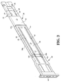
Fig. 3 is a perspective view to show that the reinforcement member, the extension support and the installation support are connected to the rail, and -
Fig. 4 is a perspective view to show that the reinforcement member, the extension support and the installation support are telescoped relative to the rail. - Referring to
Figs. 1 and2 , the reinforcement and adjustment device of the present invention comprises arail 10 which comprises atop wall 12a, abottom wall 12b located corresponding to thetop wall 12a, and asidewall 14 connected between thetop wall 12a and thebottom wall 12b. Thesidewall 14 has afirst face 16a and asecond face 16b which is located opposite to thefirst face 16a. A space between thetop wall 12a, thebottom wall 12b and thefirst face 16a of thesidewall 14 is defined as aslide path 18. Thesecond face 16b of thesidewall 14 defines arecessed reinforcement path 20. The reinforcement path (20) is substantially parallel to the slide path (18). Preferably, thereinforcement path 20 is formed substantially along the longitudinal direction of therail 10 to reinforce therail 10 by the multiple bent portions of thereinforcement path 20. Besides, atop protrusion 22 extends downward from thesecond face 16b of thesidewall 14 of therail 10 and reaches into thereinforcement path 20, and alower protrusion 24 extends upward from thesecond face 16b of thesidewall 14 of therail 10 and reaches into thereinforcement path 20. Preferably, the top andlower protrusions - A
reinforcement member 26 is movably located in thereinforcement path 20 of thesecond face 16b of thesidewall 14 of therail 10. Anextension support 28 is fixed to thereinforcement member 26. The top andlower protrusions reinforcement member 26 to be movable in thereinforcement path 20 along the longitudinal direction of therail 10. Furthermore, theextension support 28 comprises afirst flange 30a, asecond flange 30b located corresponding to thefirst flange 30a, and afirst connection portion 32 connected between thefirst flange 30a and thesecond flange 30b. Thefirst flange 30a, thesecond flange 30b and thefirst connection portion 32 define an arm. Thefirst connection portion 32 of theextension support 28 is connected to thereinforcement member 26 by way of riveting, thefirst flange 30a and thesecond flange 30b hold thetop wall 12a and thebottom wall 12b of therail 10, so that thereinforcement member 26 and theextension support 28 are slidable relative to therail 10, and the slide assembly is properly reinforced. - An
installation support 34 is movably connected to theextension support 28. Theinstallation support 34 has afirst support portion 36a, asecond support portion 36b located corresponding to thefirst support portion 36a, and asecond connection portion 38 connected between thefirst support portion 36a and thesecond support portion 36b. Preferably, thesecond connection portion 38 of theinstallation support 34 has two separatedlongitudinal slots 40 and at least twopositioning members 42 respectively extend thelongitudinal slots 40 and are connected to theextension support 28. By this arrangement, theinstallation support 34 is movable relative to theextension support 28 and along thelongitudinal slots 40 by thepositioning members 42. Thefirst support portion 36a contacts thefirst flange 30a and thesecond support portion 36b contacts thesecond flange 30b. Aninstallation portion 44 is connected to an end of theinstallation support 34. - Referring to
Figs. 3 and4 , when theextension support 28 is moved relative to therail 10, thereinforcement member 26 is moved along thereinforcement path 20 simultaneously so as to have the first stage of adjustment. Furthermore, theinstallation support 34 is movable relative to theextension support 28 to have the second stage of adjustment. Therefore, theinstallation support 34 can be used to the racks of different depths. Besides, thereinforcement member 26 is moved in thereinforcement path 20 of therail 10 provides therail 10 with options to reinforce desired sections. - While we have shown and described the embodiment in accordance with the present invention, it should be clear to those skilled in the art that further embodiments may be made without departing from the scope of the present invention.
Claims (5)
- A reinforcement and adjustment device comprising:a rail (10) having a top wall (12a), a bottom wall (12b) located corresponding to the top wall (12a), and a sidewall (14) connected between the top wall (12a) and the bottom wall (12b), the sidewall (14) having a first face (16a) and a second face (16b) which is located opposite to the first face (16a), a space between the top wall (12a), the bottom wall (12b) and the first face (16a) of the sidewall (14) defining a slide path (18), the second face (16b) of the sidewall (14) defining a recessed reinforcement path (20);a reinforcement member (26) movably located in the reinforcement path (20) of the rail (10);an extension support (28) fixed to the reinforcement member (26) and having a first flange (30a), a second flange (30b) located corresponding to the first flange (30a), and a first connection portion (32) connected between the first flange (30a) and the second flange (30b), the first flange (30a), the second flange (30b) and the first connection portion (32) defining an arm, the first flange (30a) and the second flange (30b) holding the top wall (12a) and the bottom wall (12b), andan installation support (34) movably connected to the extension support (28) and an installation portion (44) connected to an end of the installation support (34).
- The device as claimed in claim 1, wherein the reinforcement path (20) is substantially parallel to the slide path (18).
- The device as claimed in claim 1, wherein a top protrusion (22) extends downward from the second face (16b) of the sidewall (14) of the rail (10) and reaches into the reinforcement path (20), a lower protrusion (24) extends upward from the second face (16b) of the sidewall (14) of the rail (10) and reaches into the reinforcement path (20), the reinforcement member (26) contacts the top and lower protrusions (22, 24) so as to hold a movement of the reinforcement member (26) in the reinforcement path (20) of the rail (10).
- The device as claimed in claim 1, wherein the installation support (34) has a first support portion (36a), a second support portion (36b) located corresponding to the first support portion (36a), and a second connection portion (38) connected between the first support portion (36a) and the second support portion (36b), the first support portion (36a) contacts the first flange (30a) and the second support portion (36b) contacts the second flange (30b).
- The device as claimed in claim 4, wherein the second connection portion (38) of the installation support (34) has two separated longitudinal slots (40) and at least two positioning members (42) respectively extend the longitudinal slots (40) and are connected to the extension support (28).
Applications Claiming Priority (1)
| Application Number | Priority Date | Filing Date | Title |
|---|---|---|---|
| TW099134831A TWI454231B (en) | 2010-10-11 | 2010-10-11 | Slide rail with reinforced and adjustable structure |
Publications (2)
| Publication Number | Publication Date |
|---|---|
| EP2438834A1 true EP2438834A1 (en) | 2012-04-11 |
| EP2438834B1 EP2438834B1 (en) | 2013-09-11 |
Family
ID=44674551
Family Applications (1)
| Application Number | Title | Priority Date | Filing Date |
|---|---|---|---|
| EP11182324.1A Active EP2438834B1 (en) | 2010-10-11 | 2011-09-22 | Reinforcement and adjustment device for slide assembly |
Country Status (4)
| Country | Link |
|---|---|
| US (1) | US8721012B2 (en) |
| EP (1) | EP2438834B1 (en) |
| JP (1) | JP3171399U (en) |
| TW (1) | TWI454231B (en) |
Cited By (3)
| Publication number | Priority date | Publication date | Assignee | Title |
|---|---|---|---|---|
| EP3094166A1 (en) * | 2015-05-15 | 2016-11-16 | King Slide Works Co., Ltd. | Slide rail assembly |
| JP2020185369A (en) * | 2019-05-15 | 2020-11-19 | 川湖科技股▲分▼有限公司 | Slide rail assembly |
| AT526835B1 (en) * | 2023-09-04 | 2024-08-15 | Blum Gmbh Julius | Procedure for mounting a profile |
Families Citing this family (20)
| Publication number | Priority date | Publication date | Assignee | Title |
|---|---|---|---|---|
| US9144173B2 (en) | 2013-02-06 | 2015-09-22 | King Slide Works Co., Ltd. | Slide rail assembly for use in rack system and reinforcement member thereof |
| CN104582397B (en) * | 2013-10-16 | 2017-05-03 | 川湖科技股份有限公司 | Slide rail assembly |
| US9504319B2 (en) * | 2014-06-13 | 2016-11-29 | Environmental Compliance Solutions, Llc | Adjustable rack and method of making and using the same |
| DE102014111806B4 (en) * | 2014-08-01 | 2025-05-22 | Rittal Gmbh & Co. Kg | Cabinet system |
| US9328769B1 (en) | 2015-01-27 | 2016-05-03 | King Slide Works Co., Ltd. | Slide rail assembly and bracket device thereof |
| EP3050462B1 (en) | 2015-01-28 | 2018-03-14 | King Slide Works Co., Ltd. | Slide rail assembly and bracket device thereof |
| US9861197B2 (en) | 2015-02-13 | 2018-01-09 | King Slide Works Co., Ltd. | Slide rail assembly |
| US9635942B2 (en) | 2015-03-26 | 2017-05-02 | King Slide Works Co., Ltd. | Slide rail assembly |
| TWI578882B (en) * | 2015-07-15 | 2017-04-11 | King Slide Works Co Ltd | Slide rail assembly |
| TWI552670B (en) * | 2015-10-06 | 2016-10-01 | King Slide Works Co Ltd | Slide rail assembly and bracket device thereof |
| US10117352B2 (en) * | 2016-01-06 | 2018-10-30 | King Slide Works Co., Ltd. | Slide rail assembly |
| CN107007050B (en) * | 2016-01-11 | 2020-12-01 | 川湖科技股份有限公司 | Slide rail assembly |
| TWI601473B (en) | 2016-10-13 | 2017-10-01 | 川湖科技股份有限公司 | Slide rail assembly |
| CN108235643B (en) * | 2016-12-21 | 2020-06-05 | 伊姆西Ip控股有限责任公司 | Guide rail for cabinet, cabinet and cabinet |
| CN108958386B (en) * | 2017-05-23 | 2021-10-01 | 鸿富锦精密电子(天津)有限公司 | Sliding rail bracket structure |
| NL2022397B1 (en) * | 2019-01-14 | 2020-08-14 | Walraven Holding Bv J Van | Profiled section element with stepped sidewall |
| CN112312713B (en) * | 2019-07-31 | 2022-08-26 | 川湖科技股份有限公司 | Slide rail mechanism |
| US11382235B2 (en) * | 2019-12-11 | 2022-07-05 | Martas Precision Slide Co., Ltd. | Fixing bracket for slide rail of open rack |
| CN114232858B (en) * | 2022-01-13 | 2023-04-21 | 三箭建设工程集团有限公司 | Waterproof grid baffle installation structure on inner side of open type clay plate curtain wall and construction method thereof |
| US12538980B2 (en) * | 2023-01-09 | 2026-02-03 | Vertiv Corporation | Universal rail kit |
Citations (4)
| Publication number | Priority date | Publication date | Assignee | Title |
|---|---|---|---|---|
| US20010040203A1 (en) * | 2000-03-17 | 2001-11-15 | Brock Patty J. | Computer server mounting apparatus |
| US20010040142A1 (en) * | 1999-10-27 | 2001-11-15 | Gerome A. Haney | Vertical locating slide bracket |
| US20060152115A1 (en) | 2005-01-07 | 2006-07-13 | William Dubon | Adjustable reinforcing bracket for telescoping slide rail assembly |
| US20100295432A1 (en) * | 2009-05-19 | 2010-11-25 | Hightower Robert C | Inset Undermounted Bracket for Drawer and Tray Slides in Cabinetry |
Family Cites Families (8)
| Publication number | Priority date | Publication date | Assignee | Title |
|---|---|---|---|---|
| US6230903B1 (en) * | 1999-10-27 | 2001-05-15 | Hewlett-Packard Company | Snap-on rack slide mounting system |
| US20020074915A1 (en) * | 2000-12-15 | 2002-06-20 | Shoei-Yuan Shih | Slideout support for server cabinet |
| DE10156931C2 (en) * | 2001-11-19 | 2003-10-30 | Rittal Gmbh & Co Kg | Universal installation kit for a device that can be built into a frame |
| US6615992B1 (en) * | 2002-03-11 | 2003-09-09 | Hewlett-Packard Development Company L.P. | Adjustable rackmount assembly |
| US20040217073A1 (en) * | 2003-05-01 | 2004-11-04 | Dobler Karl J. | System and method for utilizing a tool-less rail in a rack |
| JP4175325B2 (en) * | 2005-01-18 | 2008-11-05 | 日本電気株式会社 | rack |
| TWM374793U (en) * | 2008-05-16 | 2010-03-01 | zhen-hong Zhuang | Multi-sectioned slide rail structure |
| US8132874B2 (en) * | 2009-05-08 | 2012-03-13 | Oracle America, Inc. | Server chassis rack rail with self-aligning, magnetic guide assembly for positioning servers in storage rack |
-
2010
- 2010-10-11 TW TW099134831A patent/TWI454231B/en active
-
2011
- 2011-08-19 JP JP2011004856U patent/JP3171399U/en not_active Expired - Lifetime
- 2011-08-30 US US13/220,966 patent/US8721012B2/en active Active
- 2011-09-22 EP EP11182324.1A patent/EP2438834B1/en active Active
Patent Citations (4)
| Publication number | Priority date | Publication date | Assignee | Title |
|---|---|---|---|---|
| US20010040142A1 (en) * | 1999-10-27 | 2001-11-15 | Gerome A. Haney | Vertical locating slide bracket |
| US20010040203A1 (en) * | 2000-03-17 | 2001-11-15 | Brock Patty J. | Computer server mounting apparatus |
| US20060152115A1 (en) | 2005-01-07 | 2006-07-13 | William Dubon | Adjustable reinforcing bracket for telescoping slide rail assembly |
| US20100295432A1 (en) * | 2009-05-19 | 2010-11-25 | Hightower Robert C | Inset Undermounted Bracket for Drawer and Tray Slides in Cabinetry |
Cited By (5)
| Publication number | Priority date | Publication date | Assignee | Title |
|---|---|---|---|---|
| EP3094166A1 (en) * | 2015-05-15 | 2016-11-16 | King Slide Works Co., Ltd. | Slide rail assembly |
| JP2020185369A (en) * | 2019-05-15 | 2020-11-19 | 川湖科技股▲分▼有限公司 | Slide rail assembly |
| AT526835B1 (en) * | 2023-09-04 | 2024-08-15 | Blum Gmbh Julius | Procedure for mounting a profile |
| AT526835A4 (en) * | 2023-09-04 | 2024-08-15 | Blum Gmbh Julius | Procedure for mounting a profile |
| TWI898811B (en) * | 2023-09-04 | 2025-09-21 | 奧地利商朱利葉斯百隆股份有限公司 | Method to assemble a moulding, moulding for a supporting structure, and furniture with the moulding |
Also Published As
| Publication number | Publication date |
|---|---|
| TWI454231B (en) | 2014-10-01 |
| US20120087606A1 (en) | 2012-04-12 |
| JP3171399U (en) | 2011-10-27 |
| TW201215349A (en) | 2012-04-16 |
| US8721012B2 (en) | 2014-05-13 |
| EP2438834B1 (en) | 2013-09-11 |
Similar Documents
| Publication | Publication Date | Title |
|---|---|---|
| EP2438834B1 (en) | Reinforcement and adjustment device for slide assembly | |
| EP2438835A1 (en) | Reinforcement device for slide assembly | |
| EP2446779B1 (en) | Slide assembly with quick-mount system | |
| JP6050314B2 (en) | Drawer guide for drawer | |
| US8028965B2 (en) | Adjustable bracket for a slide assembly | |
| EP3154320B1 (en) | Slide rail assembly and bracket device thereof | |
| US8733866B2 (en) | Combination of bracket and slide assembly | |
| EP3094165B1 (en) | Slide rail assembly | |
| JP5964410B2 (en) | Drawer rail system | |
| EP3197252A1 (en) | Slide rail assembly and guiding mechanism thereof | |
| KR20160065725A (en) | Fixing apparatus for sliding rail | |
| JP2021522000A (en) | Slider device for elevating columns | |
| EP3094166B1 (en) | Slide rail assembly | |
| EP3310033B1 (en) | Slide rail assembly | |
| EP3014716B1 (en) | Mounting frame and rail for electronics and instrumentation enclosure | |
| CN104363793B (en) | Drawer rear wall | |
| EP2777431B1 (en) | Support structure for support bracket and rail | |
| EP2389837A1 (en) | Elastic force adjustment device for slide assembly | |
| CN111972885B (en) | Slide rail assembly | |
| JP4713527B2 (en) | Support device | |
| KR101697763B1 (en) | Structure of doorroom for protecting outdoor of doorguideshoe | |
| JP5905478B2 (en) | Support rail for the drawer bottom | |
| EP2813160A1 (en) | Fixing device for a slide assembly | |
| CN112261891A (en) | Panel for drawer | |
| CN109555762B (en) | Clamp mounting base |
Legal Events
| Date | Code | Title | Description |
|---|---|---|---|
| AK | Designated contracting states |
Kind code of ref document: A1 Designated state(s): AL AT BE BG CH CY CZ DE DK EE ES FI FR GB GR HR HU IE IS IT LI LT LU LV MC MK MT NL NO PL PT RO RS SE SI SK SM TR |
|
| AX | Request for extension of the european patent |
Extension state: BA ME |
|
| PUAI | Public reference made under article 153(3) epc to a published international application that has entered the european phase |
Free format text: ORIGINAL CODE: 0009012 |
|
| 17P | Request for examination filed |
Effective date: 20121011 |
|
| RIC1 | Information provided on ipc code assigned before grant |
Ipc: A47B 88/08 20060101ALI20130206BHEP Ipc: A47B 88/04 20060101AFI20130206BHEP |
|
| GRAP | Despatch of communication of intention to grant a patent |
Free format text: ORIGINAL CODE: EPIDOSNIGR1 |
|
| GRAS | Grant fee paid |
Free format text: ORIGINAL CODE: EPIDOSNIGR3 |
|
| GRAA | (expected) grant |
Free format text: ORIGINAL CODE: 0009210 |
|
| AK | Designated contracting states |
Kind code of ref document: B1 Designated state(s): AL AT BE BG CH CY CZ DE DK EE ES FI FR GB GR HR HU IE IS IT LI LT LU LV MC MK MT NL NO PL PT RO RS SE SI SK SM TR |
|
| REG | Reference to a national code |
Ref country code: GB Ref legal event code: FG4D |
|
| REG | Reference to a national code |
Ref country code: CH Ref legal event code: EP |
|
| REG | Reference to a national code |
Ref country code: AT Ref legal event code: REF Ref document number: 631126 Country of ref document: AT Kind code of ref document: T Effective date: 20130915 |
|
| REG | Reference to a national code |
Ref country code: IE Ref legal event code: FG4D |
|
| REG | Reference to a national code |
Ref country code: DE Ref legal event code: R096 Ref document number: 602011003014 Country of ref document: DE Effective date: 20131107 |
|
| PG25 | Lapsed in a contracting state [announced via postgrant information from national office to epo] |
Ref country code: NO Free format text: LAPSE BECAUSE OF FAILURE TO SUBMIT A TRANSLATION OF THE DESCRIPTION OR TO PAY THE FEE WITHIN THE PRESCRIBED TIME-LIMIT Effective date: 20131211 Ref country code: LT Free format text: LAPSE BECAUSE OF FAILURE TO SUBMIT A TRANSLATION OF THE DESCRIPTION OR TO PAY THE FEE WITHIN THE PRESCRIBED TIME-LIMIT Effective date: 20130911 Ref country code: SE Free format text: LAPSE BECAUSE OF FAILURE TO SUBMIT A TRANSLATION OF THE DESCRIPTION OR TO PAY THE FEE WITHIN THE PRESCRIBED TIME-LIMIT Effective date: 20130911 Ref country code: HR Free format text: LAPSE BECAUSE OF FAILURE TO SUBMIT A TRANSLATION OF THE DESCRIPTION OR TO PAY THE FEE WITHIN THE PRESCRIBED TIME-LIMIT Effective date: 20130911 Ref country code: CY Free format text: LAPSE BECAUSE OF FAILURE TO SUBMIT A TRANSLATION OF THE DESCRIPTION OR TO PAY THE FEE WITHIN THE PRESCRIBED TIME-LIMIT Effective date: 20130821 |
|
| REG | Reference to a national code |
Ref country code: NL Ref legal event code: VDEP Effective date: 20130911 |
|
| REG | Reference to a national code |
Ref country code: AT Ref legal event code: MK05 Ref document number: 631126 Country of ref document: AT Kind code of ref document: T Effective date: 20130911 |
|
| REG | Reference to a national code |
Ref country code: LT Ref legal event code: MG4D |
|
| PG25 | Lapsed in a contracting state [announced via postgrant information from national office to epo] |
Ref country code: FI Free format text: LAPSE BECAUSE OF FAILURE TO SUBMIT A TRANSLATION OF THE DESCRIPTION OR TO PAY THE FEE WITHIN THE PRESCRIBED TIME-LIMIT Effective date: 20130911 Ref country code: SI Free format text: LAPSE BECAUSE OF FAILURE TO SUBMIT A TRANSLATION OF THE DESCRIPTION OR TO PAY THE FEE WITHIN THE PRESCRIBED TIME-LIMIT Effective date: 20130911 Ref country code: LV Free format text: LAPSE BECAUSE OF FAILURE TO SUBMIT A TRANSLATION OF THE DESCRIPTION OR TO PAY THE FEE WITHIN THE PRESCRIBED TIME-LIMIT Effective date: 20130911 |
|
| PG25 | Lapsed in a contracting state [announced via postgrant information from national office to epo] |
Ref country code: CY Free format text: LAPSE BECAUSE OF FAILURE TO SUBMIT A TRANSLATION OF THE DESCRIPTION OR TO PAY THE FEE WITHIN THE PRESCRIBED TIME-LIMIT Effective date: 20130911 Ref country code: BE Free format text: LAPSE BECAUSE OF FAILURE TO SUBMIT A TRANSLATION OF THE DESCRIPTION OR TO PAY THE FEE WITHIN THE PRESCRIBED TIME-LIMIT Effective date: 20130911 |
|
| PG25 | Lapsed in a contracting state [announced via postgrant information from national office to epo] |
Ref country code: IS Free format text: LAPSE BECAUSE OF FAILURE TO SUBMIT A TRANSLATION OF THE DESCRIPTION OR TO PAY THE FEE WITHIN THE PRESCRIBED TIME-LIMIT Effective date: 20140111 Ref country code: RO Free format text: LAPSE BECAUSE OF FAILURE TO SUBMIT A TRANSLATION OF THE DESCRIPTION OR TO PAY THE FEE WITHIN THE PRESCRIBED TIME-LIMIT Effective date: 20130911 Ref country code: SK Free format text: LAPSE BECAUSE OF FAILURE TO SUBMIT A TRANSLATION OF THE DESCRIPTION OR TO PAY THE FEE WITHIN THE PRESCRIBED TIME-LIMIT Effective date: 20130911 Ref country code: NL Free format text: LAPSE BECAUSE OF FAILURE TO SUBMIT A TRANSLATION OF THE DESCRIPTION OR TO PAY THE FEE WITHIN THE PRESCRIBED TIME-LIMIT Effective date: 20130911 Ref country code: EE Free format text: LAPSE BECAUSE OF FAILURE TO SUBMIT A TRANSLATION OF THE DESCRIPTION OR TO PAY THE FEE WITHIN THE PRESCRIBED TIME-LIMIT Effective date: 20130911 |
|
| PG25 | Lapsed in a contracting state [announced via postgrant information from national office to epo] |
Ref country code: ES Free format text: LAPSE BECAUSE OF FAILURE TO SUBMIT A TRANSLATION OF THE DESCRIPTION OR TO PAY THE FEE WITHIN THE PRESCRIBED TIME-LIMIT Effective date: 20130911 Ref country code: AT Free format text: LAPSE BECAUSE OF FAILURE TO SUBMIT A TRANSLATION OF THE DESCRIPTION OR TO PAY THE FEE WITHIN THE PRESCRIBED TIME-LIMIT Effective date: 20130911 Ref country code: PL Free format text: LAPSE BECAUSE OF FAILURE TO SUBMIT A TRANSLATION OF THE DESCRIPTION OR TO PAY THE FEE WITHIN THE PRESCRIBED TIME-LIMIT Effective date: 20130911 |
|
| REG | Reference to a national code |
Ref country code: DE Ref legal event code: R097 Ref document number: 602011003014 Country of ref document: DE |
|
| PG25 | Lapsed in a contracting state [announced via postgrant information from national office to epo] |
Ref country code: PT Free format text: LAPSE BECAUSE OF FAILURE TO SUBMIT A TRANSLATION OF THE DESCRIPTION OR TO PAY THE FEE WITHIN THE PRESCRIBED TIME-LIMIT Effective date: 20140113 Ref country code: MC Free format text: LAPSE BECAUSE OF FAILURE TO SUBMIT A TRANSLATION OF THE DESCRIPTION OR TO PAY THE FEE WITHIN THE PRESCRIBED TIME-LIMIT Effective date: 20130911 |
|
| REG | Reference to a national code |
Ref country code: IE Ref legal event code: MM4A |
|
| PLBE | No opposition filed within time limit |
Free format text: ORIGINAL CODE: 0009261 |
|
| STAA | Information on the status of an ep patent application or granted ep patent |
Free format text: STATUS: NO OPPOSITION FILED WITHIN TIME LIMIT |
|
| PG25 | Lapsed in a contracting state [announced via postgrant information from national office to epo] |
Ref country code: IE Free format text: LAPSE BECAUSE OF NON-PAYMENT OF DUE FEES Effective date: 20130922 |
|
| REG | Reference to a national code |
Ref country code: FR Ref legal event code: ST Effective date: 20140709 |
|
| 26N | No opposition filed |
Effective date: 20140612 |
|
| PG25 | Lapsed in a contracting state [announced via postgrant information from national office to epo] |
Ref country code: IT Free format text: LAPSE BECAUSE OF FAILURE TO SUBMIT A TRANSLATION OF THE DESCRIPTION OR TO PAY THE FEE WITHIN THE PRESCRIBED TIME-LIMIT Effective date: 20130911 |
|
| REG | Reference to a national code |
Ref country code: DE Ref legal event code: R097 Ref document number: 602011003014 Country of ref document: DE Effective date: 20140612 |
|
| PG25 | Lapsed in a contracting state [announced via postgrant information from national office to epo] |
Ref country code: DK Free format text: LAPSE BECAUSE OF FAILURE TO SUBMIT A TRANSLATION OF THE DESCRIPTION OR TO PAY THE FEE WITHIN THE PRESCRIBED TIME-LIMIT Effective date: 20130911 |
|
| PG25 | Lapsed in a contracting state [announced via postgrant information from national office to epo] |
Ref country code: FR Free format text: LAPSE BECAUSE OF NON-PAYMENT OF DUE FEES Effective date: 20131112 |
|
| REG | Reference to a national code |
Ref country code: CH Ref legal event code: PL |
|
| PG25 | Lapsed in a contracting state [announced via postgrant information from national office to epo] |
Ref country code: SM Free format text: LAPSE BECAUSE OF FAILURE TO SUBMIT A TRANSLATION OF THE DESCRIPTION OR TO PAY THE FEE WITHIN THE PRESCRIBED TIME-LIMIT Effective date: 20130911 |
|
| PG25 | Lapsed in a contracting state [announced via postgrant information from national office to epo] |
Ref country code: MT Free format text: LAPSE BECAUSE OF FAILURE TO SUBMIT A TRANSLATION OF THE DESCRIPTION OR TO PAY THE FEE WITHIN THE PRESCRIBED TIME-LIMIT Effective date: 20130911 Ref country code: TR Free format text: LAPSE BECAUSE OF FAILURE TO SUBMIT A TRANSLATION OF THE DESCRIPTION OR TO PAY THE FEE WITHIN THE PRESCRIBED TIME-LIMIT Effective date: 20130911 |
|
| PG25 | Lapsed in a contracting state [announced via postgrant information from national office to epo] |
Ref country code: RS Free format text: LAPSE BECAUSE OF FAILURE TO SUBMIT A TRANSLATION OF THE DESCRIPTION OR TO PAY THE FEE WITHIN THE PRESCRIBED TIME-LIMIT Effective date: 20131211 Ref country code: MK Free format text: LAPSE BECAUSE OF FAILURE TO SUBMIT A TRANSLATION OF THE DESCRIPTION OR TO PAY THE FEE WITHIN THE PRESCRIBED TIME-LIMIT Effective date: 20130911 Ref country code: LI Free format text: LAPSE BECAUSE OF NON-PAYMENT OF DUE FEES Effective date: 20140930 Ref country code: LU Free format text: LAPSE BECAUSE OF NON-PAYMENT OF DUE FEES Effective date: 20130922 Ref country code: HU Free format text: LAPSE BECAUSE OF FAILURE TO SUBMIT A TRANSLATION OF THE DESCRIPTION OR TO PAY THE FEE WITHIN THE PRESCRIBED TIME-LIMIT; INVALID AB INITIO Effective date: 20110922 Ref country code: CH Free format text: LAPSE BECAUSE OF NON-PAYMENT OF DUE FEES Effective date: 20140930 Ref country code: BG Free format text: LAPSE BECAUSE OF FAILURE TO SUBMIT A TRANSLATION OF THE DESCRIPTION OR TO PAY THE FEE WITHIN THE PRESCRIBED TIME-LIMIT Effective date: 20130911 |
|
| PG25 | Lapsed in a contracting state [announced via postgrant information from national office to epo] |
Ref country code: GR Free format text: LAPSE BECAUSE OF NON-PAYMENT OF DUE FEES Effective date: 20130911 |
|
| REG | Reference to a national code |
Ref country code: DE Ref legal event code: R079 Ref document number: 602011003014 Country of ref document: DE Free format text: PREVIOUS MAIN CLASS: A47B0088040000 Ipc: A47B0088400000 |
|
| PG25 | Lapsed in a contracting state [announced via postgrant information from national office to epo] |
Ref country code: AL Free format text: LAPSE BECAUSE OF FAILURE TO SUBMIT A TRANSLATION OF THE DESCRIPTION OR TO PAY THE FEE WITHIN THE PRESCRIBED TIME-LIMIT Effective date: 20130911 |
|
| PGFP | Annual fee paid to national office [announced via postgrant information from national office to epo] |
Ref country code: DE Payment date: 20250714 Year of fee payment: 15 |
|
| PGFP | Annual fee paid to national office [announced via postgrant information from national office to epo] |
Ref country code: GB Payment date: 20250708 Year of fee payment: 15 |
|
| PGFP | Annual fee paid to national office [announced via postgrant information from national office to epo] |
Ref country code: CZ Payment date: 20250911 Year of fee payment: 15 |