EP2437951B1 - A support means, a device for attaching a first vehicle member to a second vehicle member and a vehicle suspension arrangement - Google Patents
A support means, a device for attaching a first vehicle member to a second vehicle member and a vehicle suspension arrangement Download PDFInfo
- Publication number
- EP2437951B1 EP2437951B1 EP10783649.6A EP10783649A EP2437951B1 EP 2437951 B1 EP2437951 B1 EP 2437951B1 EP 10783649 A EP10783649 A EP 10783649A EP 2437951 B1 EP2437951 B1 EP 2437951B1
- Authority
- EP
- European Patent Office
- Prior art keywords
- rigid elements
- flexible element
- edge surfaces
- support means
- vehicle
- Prior art date
- Legal status (The legal status is an assumption and is not a legal conclusion. Google has not performed a legal analysis and makes no representation as to the accuracy of the status listed.)
- Not-in-force
Links
- 239000000725 suspension Substances 0.000 title claims description 41
- 239000007787 solid Substances 0.000 claims description 4
- 230000013011 mating Effects 0.000 description 3
- 239000000463 material Substances 0.000 description 2
- 239000007769 metal material Substances 0.000 description 2
- 239000000853 adhesive Substances 0.000 description 1
- 230000001070 adhesive effect Effects 0.000 description 1
- 238000010276 construction Methods 0.000 description 1
- 239000003292 glue Substances 0.000 description 1
- 229910052751 metal Inorganic materials 0.000 description 1
- 238000012986 modification Methods 0.000 description 1
- 230000004048 modification Effects 0.000 description 1
- 239000003381 stabilizer Substances 0.000 description 1
- 239000000126 substance Substances 0.000 description 1
Images


Classifications
-
- B—PERFORMING OPERATIONS; TRANSPORTING
- B60—VEHICLES IN GENERAL
- B60G—VEHICLE SUSPENSION ARRANGEMENTS
- B60G11/00—Resilient suspensions characterised by arrangement, location or kind of springs
- B60G11/02—Resilient suspensions characterised by arrangement, location or kind of springs having leaf springs only
- B60G11/10—Resilient suspensions characterised by arrangement, location or kind of springs having leaf springs only characterised by means specially adapted for attaching the spring to axle or sprung part of the vehicle
- B60G11/113—Mountings on the axle
-
- F—MECHANICAL ENGINEERING; LIGHTING; HEATING; WEAPONS; BLASTING
- F16—ENGINEERING ELEMENTS AND UNITS; GENERAL MEASURES FOR PRODUCING AND MAINTAINING EFFECTIVE FUNCTIONING OF MACHINES OR INSTALLATIONS; THERMAL INSULATION IN GENERAL
- F16F—SPRINGS; SHOCK-ABSORBERS; MEANS FOR DAMPING VIBRATION
- F16F1/00—Springs
- F16F1/02—Springs made of steel or other material having low internal friction; Wound, torsion, leaf, cup, ring or the like springs, the material of the spring not being relevant
- F16F1/18—Leaf springs
- F16F1/26—Attachments or mountings
- F16F1/30—Attachments or mountings comprising intermediate pieces made of rubber or similar elastic material
-
- F—MECHANICAL ENGINEERING; LIGHTING; HEATING; WEAPONS; BLASTING
- F16—ENGINEERING ELEMENTS AND UNITS; GENERAL MEASURES FOR PRODUCING AND MAINTAINING EFFECTIVE FUNCTIONING OF MACHINES OR INSTALLATIONS; THERMAL INSULATION IN GENERAL
- F16F—SPRINGS; SHOCK-ABSORBERS; MEANS FOR DAMPING VIBRATION
- F16F1/00—Springs
- F16F1/36—Springs made of rubber or other material having high internal friction, e.g. thermoplastic elastomers
- F16F1/373—Springs made of rubber or other material having high internal friction, e.g. thermoplastic elastomers characterised by having a particular shape
-
- F—MECHANICAL ENGINEERING; LIGHTING; HEATING; WEAPONS; BLASTING
- F16—ENGINEERING ELEMENTS AND UNITS; GENERAL MEASURES FOR PRODUCING AND MAINTAINING EFFECTIVE FUNCTIONING OF MACHINES OR INSTALLATIONS; THERMAL INSULATION IN GENERAL
- F16F—SPRINGS; SHOCK-ABSORBERS; MEANS FOR DAMPING VIBRATION
- F16F1/00—Springs
- F16F1/36—Springs made of rubber or other material having high internal friction, e.g. thermoplastic elastomers
- F16F1/42—Springs made of rubber or other material having high internal friction, e.g. thermoplastic elastomers characterised by the mode of stressing
- F16F1/44—Springs made of rubber or other material having high internal friction, e.g. thermoplastic elastomers characterised by the mode of stressing loaded mainly in compression
- F16F1/445—Springs made of rubber or other material having high internal friction, e.g. thermoplastic elastomers characterised by the mode of stressing loaded mainly in compression the spring material being contained in a generally closed space
-
- B—PERFORMING OPERATIONS; TRANSPORTING
- B60—VEHICLES IN GENERAL
- B60G—VEHICLE SUSPENSION ARRANGEMENTS
- B60G2202/00—Indexing codes relating to the type of spring, damper or actuator
- B60G2202/10—Type of spring
- B60G2202/11—Leaf spring
- B60G2202/112—Leaf spring longitudinally arranged
-
- B—PERFORMING OPERATIONS; TRANSPORTING
- B60—VEHICLES IN GENERAL
- B60G—VEHICLE SUSPENSION ARRANGEMENTS
- B60G2204/00—Indexing codes related to suspensions per se or to auxiliary parts
- B60G2204/10—Mounting of suspension elements
- B60G2204/12—Mounting of springs or dampers
- B60G2204/121—Mounting of leaf springs
-
- B—PERFORMING OPERATIONS; TRANSPORTING
- B60—VEHICLES IN GENERAL
- B60G—VEHICLE SUSPENSION ARRANGEMENTS
- B60G2204/00—Indexing codes related to suspensions per se or to auxiliary parts
- B60G2204/40—Auxiliary suspension parts; Adjustment of suspensions
- B60G2204/43—Fittings, brackets or knuckles
- B60G2204/4306—Bracket or knuckle for rigid axles, e.g. for clamping
-
- B—PERFORMING OPERATIONS; TRANSPORTING
- B60—VEHICLES IN GENERAL
- B60G—VEHICLE SUSPENSION ARRANGEMENTS
- B60G2206/00—Indexing codes related to the manufacturing of suspensions: constructional features, the materials used, procedures or tools
- B60G2206/01—Constructional features of suspension elements, e.g. arms, dampers, springs
- B60G2206/80—Manufacturing procedures
- B60G2206/82—Joining
- B60G2206/8207—Joining by screwing
-
- B—PERFORMING OPERATIONS; TRANSPORTING
- B60—VEHICLES IN GENERAL
- B60G—VEHICLE SUSPENSION ARRANGEMENTS
- B60G2300/00—Indexing codes relating to the type of vehicle
- B60G2300/02—Trucks; Load vehicles
- B60G2300/026—Heavy duty trucks
-
- F—MECHANICAL ENGINEERING; LIGHTING; HEATING; WEAPONS; BLASTING
- F16—ENGINEERING ELEMENTS AND UNITS; GENERAL MEASURES FOR PRODUCING AND MAINTAINING EFFECTIVE FUNCTIONING OF MACHINES OR INSTALLATIONS; THERMAL INSULATION IN GENERAL
- F16B—DEVICES FOR FASTENING OR SECURING CONSTRUCTIONAL ELEMENTS OR MACHINE PARTS TOGETHER, e.g. NAILS, BOLTS, CIRCLIPS, CLAMPS, CLIPS OR WEDGES; JOINTS OR JOINTING
- F16B7/00—Connections of rods or tubes, e.g. of non-circular section, mutually, including resilient connections
- F16B7/04—Clamping or clipping connections
- F16B7/044—Clamping or clipping connections for rods or tubes being in angled relationship
- F16B7/048—Clamping or clipping connections for rods or tubes being in angled relationship for rods or for tubes without using the innerside thereof
Definitions
- the first vehicle member will below be referred to as a vehicle suspension member.
- the second vehicle member will below be referred to as a vehicle axle.
- a device is arranged for attaching the vehicle suspension member to the vehicle axle, wherein the device comprises said two U-bolts and the support means (normalcy called saddle bracket) for supporting the U-bolts.
- the saddle bracket forms a metallic element and is positioned on top of the spring member.
- the U-bolts are positioned so that they straddle the saddle bracket and the spring member at a distance from each other.
- the legs of the U-bolts extend downwardly and a U-bolt cross element connecting the legs seat on the saddle bracket.
- the device comprises means for securing the distal ends of the U-bolts.
- the U-bolts should be tightened extremely hard. However, due to relaxation, the U-bolts may be somewhat loosened during operation. This problem also contributes to the play between the rounded surfaces of the U-bolts and the saddle bracket. The play due to relaxation is more problematic the shorter the legs of the U-bolt are. In a truck, the legs of the U-bolts for the front axle are substantially shorter than the legs of the U-bolts for the rear axles. Thus, this problem is more evident at the front axle suspension.
- US 1 952 128 discloses a spring supports or stabilizers adapted to hold the springs and axles, as well as the axle housings, in alignment.
- US 2006/0103103 discloses a saddle which is configured to support two spaced apart U-bolts for attaching a vehicle suspension member to a vehicle axle.
- the saddle is made of a ductile material and comprises troughs that are configured to fit U-bolts.
- JP 62 075 144 discloses an elastic body and a metallic plate which are fixed to each other by adhesives and which are configured to support a U-bolt.
- US 6,352,245 discloses a member for connecting a front axle and front leaf spring.
- a support member is positioned between the leaf spring and a pair of U-bolts.
- US 2005/0253351 discloses a mount interface for mounting a vehicle suspension to an axle housing. Support members are positioned between U-bolts and the vehicle suspension.
- BE 464 855 discloses an assembly device for rails and sleepers which is applicable to pre-constraint sleepers.
- An object of the invention is to achieve a support means which creates conditions for a longer life of a suspension device, and especially the U-bolts, during operation.
- a support means according to claim 1.
- the support means comprises two opposed edge surfaces, each configured for contacting an inner surface of the U-bolts wherein two at least partly spaced, rigid elements are provided, each comprising one of said edge, wherein the two rigid elements are biased in a direction separating the elements.
- the relative movement of the two opposed edge surfaces allows a relative movement of the two opposed edge surfaces towards each other during mounting.
- This design of the support means creates conditions for a tight fit between the two opposed edge surfaces of the support means and the corresponding inner surfaces (inner corners) of the U-bolts during operation. More specifically, the flexibility of the support means allows for a tight fit between the edge surfaces and the U-bolts irrespective of any misalignment between the support means and the U-bolts during mounting.
- This design of the support means further creates conditions for using thinner U-bolts than prior art with the same clamping force or a higher clamping force. This in turn reduces the risk of clamping relaxation.
- the rigid elements are biased in the separating direction by at least one control surface which controls movement of the rigid elements relative to each other when the rigid elements move along the control surface.
- the rigid elements are biased in the direction separating the elements by a flexible element arranged between the rigid elements, which flexible element is adapted for allowing a relative movement of the two opposed edge surfaces.
- the flexibility of the support means allows for a tight fit between the edge surfaces and the U-bolts irrespective of any misalignment between the support means and the U-bolts during mounting.
- the flexible element is positioned between the two opposed edge surfaces. This design creates conditions for a robust and space-efficient support means.
- the support means comprises two at least partly spaced, rigid elements, that each rigid element comprises one of said edge surfaces and that the flexible element is positioned between the rigid elements. Due to this design, the flexible element allows movement between the two rigid elements.
- the flexible element and the two spaced, rigid elements are connected to each other. This can be achieved in several different ways, such as a firm attachment of the mating surfaces, such as a chemical bonding, glue or the like.
- the flexible element and the two spaced, rigid elements are designed with complimentary shaped surfaces for achieving a form fit.
- Figure 1 shows a truck ,1 in a perspective view from behind. More precisely, a semi-trailer tractor is shown in figure 1 . A semi-trailer can be connected to the semi-tractor 1 via a so-called fifth wheel (not shown).
- the suspension arrangement 3 comprises a first vehicle member 5 in the form of a suspension member extending in a longitudinal (front-to-rear) direction of the vehicle. Opposite ends of the suspension member 5 are rigidly connected to one of said frame side members 2. More precisely, the suspension member forms a leaf spring.
- the suspension arrangement 3 further comprises a second vehicle member 6 in the form of a transverse vehicle member.
- transverse vehicle member means a member extending in a vehicle transverse direction, i.e. in a direction perpendicular to the longitudinal direction of the vehicle.
- the transverse member forms a vehicle axle (or vehicle axle housing).
- the suspension arrangement 3 further comprises a device 7 for attaching the vehicle suspension member 5 to the vehicle axle 6.
- FIG. 2 shows the vehicle suspension device 7 according to a first embodiment.
- the suspension device 7 comprises a vehicle suspension support means 8 for supporting two spaced U-bolts 9.
- the support means 8 is formed by a block, which is configured to be positioned on top of and in contact with the suspension member 5.
- the U-bolts 9 are configured to straddle the support means 8 at a distance from each other. Further, the U-bolts 9 are configured to straddle the vehicle suspension member 5.
- the device 7 comprises means 15 for securing distal ends of the U-bolt legs in relation to the vehicle axle 6.
- the support means 8 comprises two at least partly spaced, rigid elements 13, 14, wherein each rigid element 13, 14 comprises one of said edge surfaces 10, 11.
- the two rigid elements 13, 14 are biased in a direction separating the elements 13, 14 by the flexible element 12 positioned between the rigid elements 13, 14.
- the rigid element preferably forms a solid, elongated piece. Further, the rigid element is preferably formed by a metallic material.
- Each of the rigid elements 13,14 and the flexible element 12 has the same cross sectional shape along its complete length.
- the rigid elements 13,14 are completely spaced from each other along the entire length of the support means 8.
- the flexible element 12 and the two spaced, rigid elements 13,14 are connected to each .other.
- Each of said edge surfaces 10,'I 1 ⁇ defines a longitudinal direction of the rigid element 13,14.
- the flexible element 12 is continuous in a direction in parallel with the longitudinal direction of said opposed edge surfaces. Thus, the flexible element 12 is not interrupted in said direction.
- the support means 8 comprises a means 16 for directing the support means to its intended position on the spring member 5.
- Said direction means 16 is formed by an opening configured for mating with a correspondingly shaped projection.
- the support means 8 has a symmetric design with regard to the position of the flexible element between said opposed edge surfaces. More specifically, the support means 8 is mirrored in a plane which is perpendicular to a plane defined by a lower, substantially flat surface of the support means 8 and which is parallel with the extension direction of the rigid elements 13, 14.
- the flexible element 12 forms a solid piece.
- the flexible element 12 is elongated with a main extension direction in parallel with the extension direction of the edge surfaces 10, 11. Further, the flexible element 12 at least to a predominant content comprises rubber.
- the flexible element is formed by a one-piece rubber unit.
- FIG. 4 shows a schematic side view of one of said U-bolts 9.
- the U-bolt comprises two legs.18, 19 extending downwardly at each end of a U-bolt cross element 20.
- the legs 18, 19 and the cross element 20 is of one-piece construction.
- the legs 18, 19 of the U-bolt 9 extend in a diverging manner from the cross element 20 towards the distal ends.
- Each of the legs 18,19 is substantially straight.
- the extension direction of one of the legs 18 crosses the extension direction of the other leg 19 at a relatively small angle, preferably ⁇ 30°.
- the angular relationship of the legs 18,19 will both guide the U-bolt 9 when mounting it to the support means 8 and also add an initial pre-pressure tension in the corner area of the U-bolt (see dashed line in figure 3C ) when it is torqued to the axle.
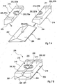
- Fig 5A-5C shows a vehicle suspension support means 108 according to a second embodiment.
- the second embodiment differs from the first embodiment in that the flexible element 112 comprises a portion 113 projecting from the elongated main portion between the rigid elements 13, 14.
- the projecting portion 113 forms a one-piece unit with the elongated main portion of the flexible element.
- the projecting portion 113 forms a bump stop.
- the projecting portion 113 projects between the U-bolts 9.
- An upper surface 114 of the projecting portion 113 is configured to allow abutment against the frame during operation and thereby form a limit for the vertical movements of the suspension member 5 and the vehicle axle 6.
- Figs. 6 to 8 depict another embodiment of the invention.
- Fig. 6 shows a perspective view of a vehicle suspension arrangement according to a further embodiment in the truck in figure 1 .
- Fig 7A, 7B schematically shows a suspension element 208 in a exploded view ( Fig. 7A ) and in an assembled view ( Fig. 7B ); and
- Fig. 8 schematically shows a U-bolt 9 during assembly.
- FIG. 6 shows the vehicle suspension device 7 according to a first embodiment.
- the suspension device 7 comprises a vehicle suspension support means 208 for supporting two spaced U-bolts 9.
- the support means 208 is formed by a block, which is configured to be positioned on top of and in contact with the suspension member 5.
- the U-bolts 9 are configured to straddle the support means 8 at a distance from each other. Further, the U-bolts 9 are configured to straddle the vehicle suspension member 5.
- the device 7 comprises means 15 for securing distal ends of the U-bolt legs in relation to the vehicle axle 6.
- the support means 208 comprises two opposed edge surfaces 210, 211, each configured for contacting an inner surface of the U-bolts. Said edge surfaces 210, 211 are elongated, substantially straight and parallel to each other.
- the support means 208 comprises a control element 200, which is adapted for allowing a relative movement of the two opposed edge surfaces 210, 211.
- the control element 200 is positioned beneath the two opposed edge surfaces 210, 211 for allowing a movement of the two opposed edge surfaces 210, 211 towards each other during mounting.
- the term inner surface refers to a region at the inner corner of the U-bolt 9.
- the support means 208 comprises two at least partly spaced, rigid elements 213, 214, wherein each rigid element 213, 214 comprises one of said edge surfaces 210, 211.
- the two rigid elements 213, 214 are biased in a direction separating the elements 213, 214 by control surfaces 202, 204 of the control element 200 positioned below the rigid elements 213, 214.
- the rigid element 213, 214 preferably forms a solid, elongated piece. Further, the rigid element is preferably formed by a metallic material.
- Each of the rigid elements 213, 214 and the control element 200 has the same cross sectional shape along its complete length. The control element 200 and the two spaced, rigid elements 213, 214 are connected to each other.
- Each of said edge surfaces 210, 211 defines a longitudinal direction of the rigid element 213, 214. Further, the control element 200 is continuous in a direction in parallel with the longitudinal direction of said opposed edge surfaces 210, 211. Thus, the control element 200 is not interrupted in said direction.
- the support means 208 comprises a means 216 for directing the support means 208 to its intended position on the spring member 5.
- Said direction means 216 is formed by an opening configured for mating with a correspondingly shaped projection.
- the direction means 216 is in the mounted stated of the rigid elements 213, 214 and the control element 200 an opening extending throughout the elements 213, 214 and the control element 200.
- Each of the rigid elements 213, 214 comprises a recess 218a, 218b which forms the upper part of the direction means 216, and the control element 200 comprises a lower part 218c of the direction means 216.
- the rigid elements 213, 214 comprise surfaces 223 and 224, respectively, at the backside which correspond the control surfaces 202, 204 of the control element 200.
- the surfaces 223, 224 are inclined with respect to the front surfaces of the rigid elements 213, 214.
- the rigid elements 213, 214 may each comprise two parallel grooves, grooves 221 a, 222a on rigid element 213 and grooves 221b, 222b on rigid element 214, which form two parallel grooves 220 for receiving the U-bolts when the rigid elements 213, 214 are assembled with the U-bolts.
- a longitudinal groove 230 is formed between the rigid elements 213, 214, which may be empty, or, in an alternative embodiment, filled with a flexible element 12 as described in the preceding embodiments.
- the rigid elements 213, 214 are forced in a separating direction when pressed down on the control surfaces 202, 204 of the control element 200.
- the rigid elements 213, 214 will slide on the control surfaces 202, 204 to the outside and give a perfect contact between the inner U-bolt radius and the outer radius of the two opposed edge surfaces 210, 211 of the rigid elements 213, 214, in the same way as depicted in Fig. 3c of the previous embodiments.
- a portion 113 can be mounted to the control element 200 projecting with a first part 242 from the elongated main portion between the,.rigid elements 213, 214 and with a second part 244 into the direction means 216.
- the projecting portion 113 may form a one-piece unit with the elongated main portion of the flexible element.
- the projecting portion 113 forms a bump stop.
- the projecting portion 113 projects between the U-bolts 9 with its upper part 242.
- An upper surface of the projecting portion 113 is configured to allow abutment against the frame during operation and thereby form a limit for the vertical movements of the suspension member 5 and the vehicle axle 6.
- the flexible element may be interrupted in a direction in parallel with the longitudinal direction of the opposed, rounded corners.
- the flexible element comprises at least one spring element, a flexible sheet structure or other flexible structure.
- the support means is not necessarily a separate member, but at least part of it may form part of a rigid structure, such as the vehicle suspension member.
- a rigid structure such as the vehicle suspension member.
- one of said two spaced, rigid elements may be formed integral with said rigid structure and the other rigid element may be formed by a movable unit.
- the invention covers also solutions wherein the flexible element is not positioned directly between the rigid elements comprising the two opposed edge surfaces in a plane defined by the extension directions of the rigid elements.
- a flexible element may be connected to each rigid element at a portion thereof facing away from the U-bolt cross element, which bridges the distance between the two U-bolt legs.
- the flexible element can be arranged below the rigid elements and between the downwardly extending U-bolt legs.
Landscapes
- Engineering & Computer Science (AREA)
- General Engineering & Computer Science (AREA)
- Mechanical Engineering (AREA)
- Health & Medical Sciences (AREA)
- Child & Adolescent Psychology (AREA)
- Body Structure For Vehicles (AREA)
- Vehicle Body Suspensions (AREA)
Description
- The present invention relates to a support means for supporting two spaced U-bolts in a device for attaching a first vehicle member to a second vehicle member, wherein the support means comprises two opposed edge surfaces, each configured for contacting an inner surface of the U-bolts. The invention is further directed to a device for attaching a first vehicle member to a second vehicle member and a vehicle suspension arrangement.
- The first vehicle member will below be referred to as a vehicle suspension member. The second vehicle member will below be referred to as a vehicle axle.
- The invention will below be described for a heavy vehicle in the form of a cargo-transporting road vehicle in the form of a truck. This should however only be regarded as one possible application and the invention may further be applied in a people-transporting vehicle, such as a bus, an agricultural machine or a work machine for transporting cargo, material, earth etc.
- In a truck, a transverse wheel axle is suspended to the vehicle frame via two elongated vehicle suspension members in the form of spring members. Each of the spring members is directed along frame side members. End portions of each spring member are connected to one of said frame aide members. The wheel axle extends perpendicularly to the frame side members (and thereby also perpendicularly to the spring member). Further, the spring member extends above the wheel axle. The wheel axle is rigidly connected to the spring member at a central position between the end portions. Further, the spring member may be in the form of a leaf spring.
- A device is arranged for attaching the vehicle suspension member to the vehicle axle, wherein the device comprises said two U-bolts and the support means (normalcy called saddle bracket) for supporting the U-bolts. The saddle bracket forms a metallic element and is positioned on top of the spring member. The U-bolts are positioned so that they straddle the saddle bracket and the spring member at a distance from each other. Thus, the legs of the U-bolts extend downwardly and a U-bolt cross element connecting the legs seat on the saddle bracket. Further, the device comprises means for securing the distal ends of the U-bolts.
- According to one prior art design, the U-bolt cross element is substantially straight and the legs extend substantially at right angles to the cross element. The inner corners at the junction of the legs and the cross element have a rounded shape. Further, the corresponding outer corners of the saddle bracket have a complimentary rounded shape for contacting the inner corners of the U-bolts. However, due to tolerances, there will be a play between the rounded surfaces of the U-bolts and the saddle bracket. This play results in high stresses in the bent parts of the U-bolts during operation. This problem may be further amplified if the saddle bracket is displaced towards one of said U-bolt corners during mounting, wherein the complete play will be present on the other side.
- Further, the U-bolts should be tightened extremely hard. However, due to relaxation, the U-bolts may be somewhat loosened during operation. This problem also contributes to the play between the rounded surfaces of the U-bolts and the saddle bracket. The play due to relaxation is more problematic the shorter the legs of the U-bolt are. In a truck, the legs of the U-bolts for the front axle are substantially shorter than the legs of the U-bolts for the rear axles. Thus, this problem is more evident at the front axle suspension.
-
US 1 952 128 discloses a spring supports or stabilizers adapted to hold the springs and axles, as well as the axle housings, in alignment. -
US 2006/0103103 discloses a saddle which is configured to support two spaced apart U-bolts for attaching a vehicle suspension member to a vehicle axle. The saddle is made of a ductile material and comprises troughs that are configured to fit U-bolts. -
JP 62 075 144 - DE 10 2004 010621 discloses a pressure plate positioned on top of parcel springs. The parcel"of springs is joined to a pivotal carrying element with an elastic U-bolt.
-
US 6,352,245 discloses a member for connecting a front axle and front leaf spring. A support member is positioned between the leaf spring and a pair of U-bolts. -
US 2005/0253351 discloses a mount interface for mounting a vehicle suspension to an axle housing. Support members are positioned between U-bolts and the vehicle suspension. -
BE 464 855 - An object of the invention is to achieve a support means which creates conditions for a longer life of a suspension device, and especially the U-bolts, during operation.
- This object is achieved by a support means according to claim 1. Thus it is achieved by a the support means comprises two opposed edge surfaces, each configured for contacting an inner surface of the U-bolts wherein two at least partly spaced, rigid elements are provided, each comprising one of said edge, wherein the two rigid elements are biased in a direction separating the elements.
- "Biased in a direction separating the elements" is to be understood that the two rigid elements would separate if let loose and have to be forced together.
- Especially, the relative movement of the two opposed edge surfaces allows a relative movement of the two opposed edge surfaces towards each other during mounting.
- This design of the support means creates conditions for a tight fit between the two opposed edge surfaces of the support means and the corresponding inner surfaces (inner corners) of the U-bolts during operation. More specifically, the flexibility of the support means allows for a tight fit between the edge surfaces and the U-bolts irrespective of any misalignment between the support means and the U-bolts during mounting.
- This design of the support means further creates conditions for using thinner U-bolts than prior art with the same clamping force or a higher clamping force. This in turn reduces the risk of clamping relaxation.
- According to an example embodiment, the rigid elements are biased in the separating direction by at least one control surface which controls movement of the rigid elements relative to each other when the rigid elements move along the control surface.
- According to an example embodiment, the rigid elements are biased in the direction separating the elements by a flexible element arranged between the rigid elements, which flexible element is adapted for allowing a relative movement of the two opposed edge surfaces. The flexibility of the support means allows for a tight fit between the edge surfaces and the U-bolts irrespective of any misalignment between the support means and the U-bolts during mounting.
- According to an example embodiment, the flexible element is positioned between the two opposed edge surfaces. This design creates conditions for a robust and space-efficient support means.
- According to a further example embodiment, the support means comprises two at least partly spaced, rigid elements, that each rigid element comprises one of said edge surfaces and that the flexible element is positioned between the rigid elements. Due to this design, the flexible element allows movement between the two rigid elements.
- According to a further example embodiment, the flexible element and the two spaced, rigid elements are connected to each other. This can be achieved in several different ways, such as a firm attachment of the mating surfaces, such as a chemical bonding, glue or the like. Preferably, the flexible element and the two spaced, rigid elements are designed with complimentary shaped surfaces for achieving a form fit.
- Further preferred embodiment and advantages thereof emerge from the description below, the figures and the claims.
- The present invention together with the above-mentioned and other objects and advantages may best be understood from the following detailed description of the embodiment(s), but not restricted to the embodiments, wherein
- Fig. 1
- is perspective view of a truck from behind;
- Fig. 2
- is a perspective view of a vehicle suspension arrangement according to a first embodiment in the truck in
figure 1 ; - Fig. 3A-3C
- show a vehicle suspension support means according to a first embodiment;
- Fig. 4
- schematically shows a U-bolt during mounting;
- Fig. 5A-5C
- show a vehicle suspension support means according to a second embodiment;
- Fig. 6
- is a perspective view of a vehicle suspension arrangement according to a further embodiment in the truck in
figure 1 ; - Fig. 7A, 7B
- schematically shows a suspension element in an exploded view (
Fig. 7A ) and in an assembled view (Fig. 7B ); and - Fig. 8
- schematically shows a U-bolt during mounting.
- In the drawings, equal or similar elements are referred to by equal reference numerals. The drawings are merely schematic representations, not intended to portray specific parameters of the invention. Moreover, the drawings are intended to depict only typical embodiments of the invention and therefore should not be considered as limiting the scope of the invention.
-
Figure 1 shows a truck ,1 in a perspective view from behind. More precisely, a semi-trailer tractor is shown infigure 1 . A semi-trailer can be connected to the semi-tractor 1 via a so-called fifth wheel (not shown). - The truck 1 comprises a
frame 2, in the form of two substantially parallel longitudinal side members, each with a U-shaped profile, which are united by a plurality of cross members (not shown). The side and cross members are joined together by bolt or rivet fastenings. Further,figure 1 shows that a vehicle suspension arrangement 3 is arranged at a front axle 4. - The suspension arrangement 3 comprises a
first vehicle member 5 in the form of a suspension member extending in a longitudinal (front-to-rear) direction of the vehicle. Opposite ends of thesuspension member 5 are rigidly connected to one of saidframe side members 2. More precisely, the suspension member forms a leaf spring. The suspension arrangement 3 further comprises asecond vehicle member 6 in the form of a transverse vehicle member. The term "transverse vehicle member" means a member extending in a vehicle transverse direction, i.e. in a direction perpendicular to the longitudinal direction of the vehicle. The transverse member forms a vehicle axle (or vehicle axle housing). - The suspension arrangement 3 further comprises a
device 7 for attaching thevehicle suspension member 5 to thevehicle axle 6. -
Figure 2 shows thevehicle suspension device 7 according to a first embodiment. Thesuspension device 7 comprises a vehicle suspension support means 8 for supporting two spaced U-bolts 9. The support means 8 is formed by a block, which is configured to be positioned on top of and in contact with thesuspension member 5. The U-bolts 9 are configured to straddle the support means 8 at a distance from each other. Further, the U-bolts 9 are configured to straddle thevehicle suspension member 5. Further, thedevice 7 comprises means 15 for securing distal ends of the U-bolt legs in relation to thevehicle axle 6. - The support means 8 comprises two opposed edge surfaces 10, 11, each configured for contacting an inner surface of the U-bolts. Said edge surfaces are elongated, substantially straight and parallel to each other. The support means 8 comprises a
flexible element 12, which is adapted for allowing a relative movement of the two opposed edge surfaces. Theflexible element 12 is positioned between the two opposed edge surfaces 10, 11 for allowing a movement of the two opposed edge surfaces 10, 11 towards each other during mounting. The term inner surface refers to a region at the inner corner of theU-bolt 9. - The support means 8 comprises two at least partly spaced,
rigid elements rigid element rigid elements elements flexible element 12 positioned between therigid elements rigid elements flexible element 12 has the same cross sectional shape along its complete length. Therigid elements flexible element 12 and the two spaced,rigid elements rigid element flexible element 12 is continuous in a direction in parallel with the longitudinal direction of said opposed edge surfaces. Thus, theflexible element 12 is not interrupted in said direction. - Further, the support means 8 comprises a
means 16 for directing the support means to its intended position on the spring member 5.- Said direction means 16 is formed by an opening configured for mating with a correspondingly shaped projection. -
Figure 3A shows a perspective view of the support means 8 and the two spaced U-bolts 9 in their intended position. Theflexible element 12 and the two spaced,rigid elements flexible element 12 and the two spaced,rigid elements - The support means 8 has a symmetric design with regard to the position of the flexible element between said opposed edge surfaces. More specifically, the support means 8 is mirrored in a plane which is perpendicular to a plane defined by a lower, substantially flat surface of the support means 8 and which is parallel with the extension direction of the
rigid elements - The
flexible element 12 forms a solid piece. Theflexible element 12 is elongated with a main extension direction in parallel with the extension direction of the edge surfaces 10, 11. Further, theflexible element 12 at least to a predominant content comprises rubber. Preferably, the flexible element is formed by a one-piece rubber unit. -
Figure 3B shows the support means 8 and the spaced U-bolts infigure 3A in a view from above.Figure 3C shows a partly cut view in the cross section A-A infigure 3B . Each of said two opposed edge surfaces 10,11 has a rounded shape (seereference numeral 11 infigure 3C ) in a plane perpendicular to said longitudinal direction of therigid element 14 along substantially the complete length. Further, theinner corner 17 of the U-bolt has a complimentary rounded shape. Due to the flexibility of therubber element 12, in operation, there is substantially no play between theinner corner 17 of the U-bolt 9 and theexternal corner 11 of the support means 8. -
Figure 4 shows a schematic side view of one of said U-bolts 9. The U-bolt comprises two legs.18, 19 extending downwardly at each end of aU-bolt cross element 20. Thelegs cross element 20 is of one-piece construction. Thelegs cross element 20 towards the distal ends. Each of thelegs legs legs 18 crosses the extension direction of theother leg 19 at a relatively small angle, preferably <30°. The angular relationship of thelegs figure 3C ) when it is torqued to the axle. - Further, an
external surface 21 of the support means 8 extending between the opposed edge surfaces 10,11 has a convex shape. Thus, the convex shape faces aninner surface 22 of theU-bolt connection element 20. -
Fig 5A-5C shows a vehicle suspension support means 108 according to a second embodiment. The second embodiment differs from the first embodiment in that theflexible element 112 comprises aportion 113 projecting from the elongated main portion between therigid elements portion 113 forms a one-piece unit with the elongated main portion of the flexible element. The projectingportion 113 forms a bump stop. The projectingportion 113 projects between the U-bolts 9. Anupper surface 114 of the projectingportion 113 is configured to allow abutment against the frame during operation and thereby form a limit for the vertical movements of thesuspension member 5 and thevehicle axle 6. -
Figs. 6 to 8 depict another embodiment of the invention.Fig. 6 shows a perspective view of a vehicle suspension arrangement according to a further embodiment in the truck infigure 1 .Fig 7A, 7B schematically shows asuspension element 208 in a exploded view (Fig. 7A ) and in an assembled view (Fig. 7B ); andFig. 8 schematically shows a U-bolt 9 during assembly. -
Figure 6 shows thevehicle suspension device 7 according to a first embodiment. Thesuspension device 7 comprises a vehicle suspension support means 208 for supporting two spaced U-bolts 9. The support means 208 is formed by a block, which is configured to be positioned on top of and in contact with thesuspension member 5. The U-bolts 9 are configured to straddle the support means 8 at a distance from each other. Further, the U-bolts 9 are configured to straddle thevehicle suspension member 5. Further, thedevice 7 comprises means 15 for securing distal ends of the U-bolt legs in relation to thevehicle axle 6. - The support means 208 comprises two opposed edge surfaces 210, 211, each configured for contacting an inner surface of the U-bolts. Said edge surfaces 210, 211 are elongated, substantially straight and parallel to each other. The support means 208 comprises a
control element 200, which is adapted for allowing a relative movement of the two opposed edge surfaces 210, 211. Thecontrol element 200 is positioned beneath the two opposed edge surfaces 210, 211 for allowing a movement of the two opposed edge surfaces 210, 211 towards each other during mounting. The term inner surface refers to a region at the inner corner of theU-bolt 9. - The support means 208 comprises two at least partly spaced,
rigid elements rigid element rigid elements elements control surfaces control element 200 positioned below therigid elements rigid element rigid elements control element 200 has the same cross sectional shape along its complete length. Thecontrol element 200 and the two spaced,rigid elements rigid element control element 200 is continuous in a direction in parallel with the longitudinal direction of said opposed edge surfaces 210, 211. Thus, thecontrol element 200 is not interrupted in said direction. - Further, the support means 208 comprises a
means 216 for directing the support means 208 to its intended position on thespring member 5. Said direction means 216 is formed by an opening configured for mating with a correspondingly shaped projection. - As seen in more detail in
Figures 7A and 7B , the direction means 216 is in the mounted stated of therigid elements control element 200 an opening extending throughout theelements control element 200. Each of therigid elements control element 200 comprises a lower part 218c of the direction means 216. - The
rigid elements surfaces control surfaces control element 200. Thesurfaces rigid elements - The
rigid elements rigid element 213 and grooves 221b, 222b onrigid element 214, which form two parallel grooves 220 for receiving the U-bolts when therigid elements longitudinal groove 230 is formed between therigid elements flexible element 12 as described in the preceding embodiments. - When the U-bolts 9 are mounted to the support means 208, as illustrated in
Figure 8 , therigid elements control surfaces control element 200. Therigid elements control surfaces rigid elements Fig. 3c of the previous embodiments. - A
portion 113 can be mounted to thecontrol element 200 projecting with afirst part 242 from the elongated main portion between the,.rigid elements second part 244 into the direction means 216. In case a flexible element is provided, the projectingportion 113 may form a one-piece unit with the elongated main portion of the flexible element. The projectingportion 113 forms a bump stop. The projectingportion 113 projects between the U-bolts 9 with itsupper part 242. An upper surface of the projectingportion 113 is configured to allow abutment against the frame during operation and thereby form a limit for the vertical movements of thesuspension member 5 and thevehicle axle 6. - The invention is not in any way limited to the above described embodiments, instead a number of alternatives and modifications are possible without departing from the scope of the following claims.
- According to an alternative design of the flexible element, it may be interrupted in a direction in parallel with the longitudinal direction of the opposed, rounded corners.
- According to an alternative, or complimentary, design of the flexible element, it comprises at least one spring element, a flexible sheet structure or other flexible structure.
- Further, the support means is not necessarily a separate member, but at least part of it may form part of a rigid structure, such as the vehicle suspension member. For example, one of said two spaced, rigid elements may be formed integral with said rigid structure and the other rigid element may be formed by a movable unit.
- Further, the support means may have a non-symmetric design with regard to the position of the flexible element between said opposed edge surfaces. In other words, one of said rigid elements may have a larger extension in a direction perpendicular to the extension direction of the edges than the other rigid element.
- Further, the flexible rubber element and the two spaced, rigid elements may be rigidly attached to each other, such as via a vulcanized joint.
- Further, the invention covers also solutions wherein the flexible element is not positioned directly between the rigid elements comprising the two opposed edge surfaces in a plane defined by the extension directions of the rigid elements. For example, a flexible element may be connected to each rigid element at a portion thereof facing away from the U-bolt cross element, which bridges the distance between the two U-bolt legs. In other words, the flexible element can be arranged below the rigid elements and between the downwardly extending U-bolt legs.
Claims (14)
- A device for attaching a first vehicle member (5) to a second vehicle member (6), wherein the device comprises two U-bolts (9) and a support means (8, 108, 208) for supporting the U-bolts, wherein the U-bolts are configured to straddle the support means (8, 108, 208) at a distance from each other, characterized in that the support means (8, 108, 208) comprises two opposed edge surfaces (10, 11, 210, 211), each configured for contacting an inner surface (17) of the U-bolts (9), wherein two at least partly spaced, rigid elements (13, 14; 213, 214) are provided, each comprising one of said edge surfaces (10, 11, 210, 211), wherein the two rigid elements (13,14; 213, 214) are biased in a direction separating the.elements (13, 14; 213, 214) during mounting.
- A device according to claim 1, characterized in that the rigid elements (13, 14; 213, 214) are biased in the separating direction by at least one control surface (202, 204) which controls movement of the rigid elements (13, 14; 213, 214) relative to each other when the rigid elements (13, 14; 213, 214) move along the control surface (202, 204).
- A device according to claim 1 or 2, characterized in that the rigid elements (13, 14; 213, 214) are biased in the direction separating the elements (13, 14; 213, 214) by a flexible element (12, 112) arranged between the rigid elements (13, 14; 213, 214), which flexible element (12,112) is adapted for allowing a relative movement of the two opposed edge surfaces (10, 11, 210, 211).
- A device according to claim 3, characterized in that the flexible element (12, 112) is positioned between the two opposed edge surfaces (10, 11, 210, 211).
- A device according to claim 3 or 4, characterized in that the flexible element (12, 112) is positioned between the rigid elements (13, 14; 213, 214).
- A device according to claim 5, characterized in that the flexible element (12, 112) and the two spaced, rigid elements (13, 14; 213, 214) are connected to each other.
- A device according to claim 5 or 6, characterized in that the flexible element (12, 112) and the two spaced, rigid elements (13,14; 213, 214) are designed with complimentary shaped surfaces for achieving a form fit.
- A device according to any one of claims 5 to 7, characterized in that each of said edge surfaces (10, 11, 210, 211) is elongated and defines a longitudinal direction of the rigid element (13, 14; 213, 214) and that the flexible element (12, 112) is continuous in a direction in parallel with said opposed edge surfaces.
- A device according to any preceding claim, characterized in that the support means (8, 108, 208) has a symmetric design with regard to the position of the flexible element (12, 112) in relation to said opposed edge surfaces (10, 11, 210, 211) and/or in that the flexible element (12, 112) forms a solid piece.
- A device according to any preceding claim, characterized in that the flexible element (12, 112) at least to a predominant content comprises rubber and/or a that each of said two opposed edge surfaces (10, 11, 210, 211) has a rounded shape.
- A device according to any preceding claim, characterized in that an external surface (21) of the support means (8) extending between the opposed edge surfaces (10, 11, 210, 211) has a convex shape.
- A device according to any one of the preceding claims, characterized in that the legs (18, 19) of the U-bolt (9) extend in a diverging manner towards the distal ends and/or that the device comprises means (15) for securing distal ends of the U-bolts (9).
- A vehicle suspension arrangement comprising a first vehicle member (5), a second vehicle member (6), and a device according to any one of the preceding claims.
- A vehicle suspension arrangement according to claim 13, characterized in that the first vehicle member (5) is a leaf spring or in that the second vehicle member (6) is a vehicle axle.
Applications Claiming Priority (2)
| Application Number | Priority Date | Filing Date | Title |
|---|---|---|---|
| PCT/SE2009/000285 WO2010140928A1 (en) | 2009-06-01 | 2009-06-01 | A support means, a device for attaching a first vehicle member to a second vehicle member and a vehicle suspension arrangement |
| PCT/SE2010/000149 WO2010140950A1 (en) | 2009-06-01 | 2010-06-01 | A support means, a device for attaching a first vehicle member to a second vehicle member and a vehicle suspension arrangement |
Publications (3)
| Publication Number | Publication Date |
|---|---|
| EP2437951A1 EP2437951A1 (en) | 2012-04-11 |
| EP2437951A4 EP2437951A4 (en) | 2012-11-07 |
| EP2437951B1 true EP2437951B1 (en) | 2016-10-12 |
Family
ID=43297917
Family Applications (2)
| Application Number | Title | Priority Date | Filing Date |
|---|---|---|---|
| EP09845599.1A Not-in-force EP2437950B1 (en) | 2009-06-01 | 2009-06-01 | A support means, a device for attaching a first vehicle member to a second vehicle member and a vehicle suspension arrangement |
| EP10783649.6A Not-in-force EP2437951B1 (en) | 2009-06-01 | 2010-06-01 | A support means, a device for attaching a first vehicle member to a second vehicle member and a vehicle suspension arrangement |
Family Applications Before (1)
| Application Number | Title | Priority Date | Filing Date |
|---|---|---|---|
| EP09845599.1A Not-in-force EP2437950B1 (en) | 2009-06-01 | 2009-06-01 | A support means, a device for attaching a first vehicle member to a second vehicle member and a vehicle suspension arrangement |
Country Status (2)
| Country | Link |
|---|---|
| EP (2) | EP2437950B1 (en) |
| WO (2) | WO2010140928A1 (en) |
Families Citing this family (3)
| Publication number | Priority date | Publication date | Assignee | Title |
|---|---|---|---|---|
| US9114685B2 (en) | 2012-08-06 | 2015-08-25 | Hendrickson Usa, L.L.C. | Reduced weight axle coupling assembly for vehicle suspension systems |
| US10513018B2 (en) | 2014-09-18 | 2019-12-24 | Atlas Copco Tools & Assembly Systems, Llc | Adaptive U-bolt joint stabilization process |
| JP6587141B2 (en) * | 2015-12-25 | 2019-10-09 | いすゞ自動車株式会社 | Bump stopper |
Citations (1)
| Publication number | Priority date | Publication date | Assignee | Title |
|---|---|---|---|---|
| BE464855A (en) * |
Family Cites Families (7)
| Publication number | Priority date | Publication date | Assignee | Title |
|---|---|---|---|---|
| US1952128A (en) | 1931-04-06 | 1934-03-27 | Frank R Hahn | Spring and stabilizer |
| JPS6275144A (en) | 1985-09-30 | 1987-04-07 | Nhk Spring Co Ltd | Spacer for laminated spring device |
| JP2917710B2 (en) * | 1992-08-28 | 1999-07-12 | 三菱自動車工業株式会社 | Rear wheel steering device such as truck |
| US6352245B1 (en) | 2000-04-19 | 2002-03-05 | International Truck And Engine Corp. | Integrated front lower shock mount, axle spacer and caster wedge |
| DE102004010621A1 (en) | 2004-03-02 | 2005-09-22 | Man Nutzfahrzeuge Ag | Axle suspension for lorry with twin axles, comprising rope segment encompassing spring parcel and pressure plate |
| US20050253351A1 (en) | 2004-05-14 | 2005-11-17 | Jaw-Ping Pan | Preloaded suspension bracket assembly for axle housing |
| US20060103103A1 (en) | 2004-11-12 | 2006-05-18 | Land Jonathan L | Lightweight, low part-count, suspension system for wheeled vehicles |
-
2009
- 2009-06-01 WO PCT/SE2009/000285 patent/WO2010140928A1/en active Application Filing
- 2009-06-01 EP EP09845599.1A patent/EP2437950B1/en not_active Not-in-force
-
2010
- 2010-06-01 WO PCT/SE2010/000149 patent/WO2010140950A1/en active Application Filing
- 2010-06-01 EP EP10783649.6A patent/EP2437951B1/en not_active Not-in-force
Patent Citations (1)
| Publication number | Priority date | Publication date | Assignee | Title |
|---|---|---|---|---|
| BE464855A (en) * |
Also Published As
| Publication number | Publication date |
|---|---|
| WO2010140950A1 (en) | 2010-12-09 |
| EP2437950B1 (en) | 2016-04-27 |
| EP2437950A4 (en) | 2012-11-07 |
| EP2437951A1 (en) | 2012-04-11 |
| EP2437950A1 (en) | 2012-04-11 |
| WO2010140928A1 (en) | 2010-12-09 |
| EP2437951A4 (en) | 2012-11-07 |
Similar Documents
| Publication | Publication Date | Title |
|---|---|---|
| CA2776799C (en) | Wheel axle suspension having clamp bodies with a protrusion for attaching an indented tubular axle to trailing arms | |
| US7896372B2 (en) | Suspension device | |
| KR100950126B1 (en) | Vehicle body structure | |
| CN102712230B (en) | Heavy-duty axle-to-beam connection | |
| CN103358848A (en) | Stabilizer bar bushing attachment assembly | |
| EP2437951B1 (en) | A support means, a device for attaching a first vehicle member to a second vehicle member and a vehicle suspension arrangement | |
| JP6507554B2 (en) | Vehicle packing box mounting bracket | |
| US20040222670A1 (en) | Cross-member at automobile front | |
| EP1120299B1 (en) | Mounting structure for suspension V-Rod | |
| CN106660760A (en) | Rail clip assembly | |
| US9096108B2 (en) | Wheel axle suspension | |
| EP2969605B1 (en) | Wheel axle suspension with rectangular axle body | |
| US20220169318A1 (en) | Joint for mounting an elongate element to a structural element in a vehicle | |
| EP1580044A1 (en) | Connection between a wheel axle of a vehicle and a said wheel axle carrying trailing arm | |
| US7980574B2 (en) | Torque rod bracket assembly | |
| CN103963584A (en) | Trailer coupling | |
| WO2018181082A1 (en) | Steering device | |
| CN114633595A (en) | Hub bracket structure | |
| CN109941343B (en) | Crossbeam structure for automobile | |
| KR100644485B1 (en) | Cross member structure of truck incoporating with spring bracket | |
| JP3890942B2 (en) | Vehicle suspension system | |
| CN216545603U (en) | Limiting block structure | |
| JPH10217741A (en) | Suspension subframe structure | |
| KR20230150082A (en) | Bushing for trailing arm | |
| JP7038010B2 (en) | Stabilizer bush |
Legal Events
| Date | Code | Title | Description |
|---|---|---|---|
| PUAI | Public reference made under article 153(3) epc to a published international application that has entered the european phase |
Free format text: ORIGINAL CODE: 0009012 |
|
| 17P | Request for examination filed |
Effective date: 20120102 |
|
| AK | Designated contracting states |
Kind code of ref document: A1 Designated state(s): AL AT BE BG CH CY CZ DE DK EE ES FI FR GB GR HR HU IE IS IT LI LT LU LV MC MK MT NL NO PL PT RO SE SI SK SM TR |
|
| DAX | Request for extension of the european patent (deleted) | ||
| A4 | Supplementary search report drawn up and despatched |
Effective date: 20121009 |
|
| RIC1 | Information provided on ipc code assigned before grant |
Ipc: B60G 11/10 20060101AFI20121003BHEP Ipc: F16B 7/00 20060101ALI20121003BHEP Ipc: B60G 9/00 20060101ALI20121003BHEP Ipc: B60G 11/113 20060101ALI20121003BHEP |
|
| 17Q | First examination report despatched |
Effective date: 20150409 |
|
| REG | Reference to a national code |
Ref country code: DE Ref legal event code: R079 Ref document number: 602010037173 Country of ref document: DE Free format text: PREVIOUS MAIN CLASS: B60G0011100000 Ipc: B60G0011113000 |
|
| GRAP | Despatch of communication of intention to grant a patent |
Free format text: ORIGINAL CODE: EPIDOSNIGR1 |
|
| RIC1 | Information provided on ipc code assigned before grant |
Ipc: F16F 1/373 20060101ALI20160418BHEP Ipc: F16B 7/04 20060101ALI20160418BHEP Ipc: F16F 1/44 20060101AFI20160418BHEP Ipc: F16F 1/30 20060101ALI20160418BHEP |
|
| RIC1 | Information provided on ipc code assigned before grant |
Ipc: F16B 7/04 20060101ALI20160426BHEP Ipc: F16F 1/373 20060101ALI20160426BHEP Ipc: F16F 1/44 20060101ALI20160426BHEP Ipc: F16F 1/30 20060101ALI20160426BHEP Ipc: B60G 11/113 20060101AFI20160426BHEP |
|
| INTG | Intention to grant announced |
Effective date: 20160512 |
|
| GRAS | Grant fee paid |
Free format text: ORIGINAL CODE: EPIDOSNIGR3 |
|
| GRAA | (expected) grant |
Free format text: ORIGINAL CODE: 0009210 |
|
| AK | Designated contracting states |
Kind code of ref document: B1 Designated state(s): AL AT BE BG CH CY CZ DE DK EE ES FI FR GB GR HR HU IE IS IT LI LT LU LV MC MK MT NL NO PL PT RO SE SI SK SM TR |
|
| REG | Reference to a national code |
Ref country code: GB Ref legal event code: FG4D |
|
| REG | Reference to a national code |
Ref country code: CH Ref legal event code: EP |
|
| REG | Reference to a national code |
Ref country code: AT Ref legal event code: REF Ref document number: 836156 Country of ref document: AT Kind code of ref document: T Effective date: 20161015 |
|
| REG | Reference to a national code |
Ref country code: IE Ref legal event code: FG4D |
|
| REG | Reference to a national code |
Ref country code: DE Ref legal event code: R096 Ref document number: 602010037173 Country of ref document: DE |
|
| REG | Reference to a national code |
Ref country code: SE Ref legal event code: TRGR |
|
| REG | Reference to a national code |
Ref country code: LT Ref legal event code: MG4D |
|
| REG | Reference to a national code |
Ref country code: NL Ref legal event code: MP Effective date: 20161012 |
|
| PG25 | Lapsed in a contracting state [announced via postgrant information from national office to epo] |
Ref country code: LV Free format text: LAPSE BECAUSE OF FAILURE TO SUBMIT A TRANSLATION OF THE DESCRIPTION OR TO PAY THE FEE WITHIN THE PRESCRIBED TIME-LIMIT Effective date: 20161012 |
|
| REG | Reference to a national code |
Ref country code: AT Ref legal event code: MK05 Ref document number: 836156 Country of ref document: AT Kind code of ref document: T Effective date: 20161012 |
|
| PG25 | Lapsed in a contracting state [announced via postgrant information from national office to epo] |
Ref country code: NO Free format text: LAPSE BECAUSE OF FAILURE TO SUBMIT A TRANSLATION OF THE DESCRIPTION OR TO PAY THE FEE WITHIN THE PRESCRIBED TIME-LIMIT Effective date: 20170112 Ref country code: GR Free format text: LAPSE BECAUSE OF FAILURE TO SUBMIT A TRANSLATION OF THE DESCRIPTION OR TO PAY THE FEE WITHIN THE PRESCRIBED TIME-LIMIT Effective date: 20170113 Ref country code: LT Free format text: LAPSE BECAUSE OF FAILURE TO SUBMIT A TRANSLATION OF THE DESCRIPTION OR TO PAY THE FEE WITHIN THE PRESCRIBED TIME-LIMIT Effective date: 20161012 |
|
| PG25 | Lapsed in a contracting state [announced via postgrant information from national office to epo] |
Ref country code: PL Free format text: LAPSE BECAUSE OF FAILURE TO SUBMIT A TRANSLATION OF THE DESCRIPTION OR TO PAY THE FEE WITHIN THE PRESCRIBED TIME-LIMIT Effective date: 20161012 Ref country code: NL Free format text: LAPSE BECAUSE OF FAILURE TO SUBMIT A TRANSLATION OF THE DESCRIPTION OR TO PAY THE FEE WITHIN THE PRESCRIBED TIME-LIMIT Effective date: 20161012 Ref country code: FI Free format text: LAPSE BECAUSE OF FAILURE TO SUBMIT A TRANSLATION OF THE DESCRIPTION OR TO PAY THE FEE WITHIN THE PRESCRIBED TIME-LIMIT Effective date: 20161012 Ref country code: AT Free format text: LAPSE BECAUSE OF FAILURE TO SUBMIT A TRANSLATION OF THE DESCRIPTION OR TO PAY THE FEE WITHIN THE PRESCRIBED TIME-LIMIT Effective date: 20161012 Ref country code: ES Free format text: LAPSE BECAUSE OF FAILURE TO SUBMIT A TRANSLATION OF THE DESCRIPTION OR TO PAY THE FEE WITHIN THE PRESCRIBED TIME-LIMIT Effective date: 20161012 Ref country code: IS Free format text: LAPSE BECAUSE OF FAILURE TO SUBMIT A TRANSLATION OF THE DESCRIPTION OR TO PAY THE FEE WITHIN THE PRESCRIBED TIME-LIMIT Effective date: 20170212 Ref country code: BE Free format text: LAPSE BECAUSE OF FAILURE TO SUBMIT A TRANSLATION OF THE DESCRIPTION OR TO PAY THE FEE WITHIN THE PRESCRIBED TIME-LIMIT Effective date: 20161012 Ref country code: PT Free format text: LAPSE BECAUSE OF FAILURE TO SUBMIT A TRANSLATION OF THE DESCRIPTION OR TO PAY THE FEE WITHIN THE PRESCRIBED TIME-LIMIT Effective date: 20170213 Ref country code: HR Free format text: LAPSE BECAUSE OF FAILURE TO SUBMIT A TRANSLATION OF THE DESCRIPTION OR TO PAY THE FEE WITHIN THE PRESCRIBED TIME-LIMIT Effective date: 20161012 |
|
| REG | Reference to a national code |
Ref country code: FR Ref legal event code: PLFP Year of fee payment: 8 |
|
| REG | Reference to a national code |
Ref country code: DE Ref legal event code: R097 Ref document number: 602010037173 Country of ref document: DE |
|
| PG25 | Lapsed in a contracting state [announced via postgrant information from national office to epo] |
Ref country code: RO Free format text: LAPSE BECAUSE OF FAILURE TO SUBMIT A TRANSLATION OF THE DESCRIPTION OR TO PAY THE FEE WITHIN THE PRESCRIBED TIME-LIMIT Effective date: 20161012 Ref country code: CZ Free format text: LAPSE BECAUSE OF FAILURE TO SUBMIT A TRANSLATION OF THE DESCRIPTION OR TO PAY THE FEE WITHIN THE PRESCRIBED TIME-LIMIT Effective date: 20161012 Ref country code: EE Free format text: LAPSE BECAUSE OF FAILURE TO SUBMIT A TRANSLATION OF THE DESCRIPTION OR TO PAY THE FEE WITHIN THE PRESCRIBED TIME-LIMIT Effective date: 20161012 Ref country code: SK Free format text: LAPSE BECAUSE OF FAILURE TO SUBMIT A TRANSLATION OF THE DESCRIPTION OR TO PAY THE FEE WITHIN THE PRESCRIBED TIME-LIMIT Effective date: 20161012 Ref country code: DK Free format text: LAPSE BECAUSE OF FAILURE TO SUBMIT A TRANSLATION OF THE DESCRIPTION OR TO PAY THE FEE WITHIN THE PRESCRIBED TIME-LIMIT Effective date: 20161012 |
|
| PLBE | No opposition filed within time limit |
Free format text: ORIGINAL CODE: 0009261 |
|
| STAA | Information on the status of an ep patent application or granted ep patent |
Free format text: STATUS: NO OPPOSITION FILED WITHIN TIME LIMIT |
|
| PG25 | Lapsed in a contracting state [announced via postgrant information from national office to epo] |
Ref country code: IT Free format text: LAPSE BECAUSE OF FAILURE TO SUBMIT A TRANSLATION OF THE DESCRIPTION OR TO PAY THE FEE WITHIN THE PRESCRIBED TIME-LIMIT Effective date: 20161012 Ref country code: BG Free format text: LAPSE BECAUSE OF FAILURE TO SUBMIT A TRANSLATION OF THE DESCRIPTION OR TO PAY THE FEE WITHIN THE PRESCRIBED TIME-LIMIT Effective date: 20170112 Ref country code: SM Free format text: LAPSE BECAUSE OF FAILURE TO SUBMIT A TRANSLATION OF THE DESCRIPTION OR TO PAY THE FEE WITHIN THE PRESCRIBED TIME-LIMIT Effective date: 20161012 |
|
| 26N | No opposition filed |
Effective date: 20170713 |
|
| PG25 | Lapsed in a contracting state [announced via postgrant information from national office to epo] |
Ref country code: SI Free format text: LAPSE BECAUSE OF FAILURE TO SUBMIT A TRANSLATION OF THE DESCRIPTION OR TO PAY THE FEE WITHIN THE PRESCRIBED TIME-LIMIT Effective date: 20161012 |
|
| PG25 | Lapsed in a contracting state [announced via postgrant information from national office to epo] |
Ref country code: MC Free format text: LAPSE BECAUSE OF FAILURE TO SUBMIT A TRANSLATION OF THE DESCRIPTION OR TO PAY THE FEE WITHIN THE PRESCRIBED TIME-LIMIT Effective date: 20161012 |
|
| REG | Reference to a national code |
Ref country code: CH Ref legal event code: PL |
|
| GBPC | Gb: european patent ceased through non-payment of renewal fee |
Effective date: 20170601 |
|
| REG | Reference to a national code |
Ref country code: IE Ref legal event code: MM4A |
|
| PG25 | Lapsed in a contracting state [announced via postgrant information from national office to epo] |
Ref country code: IE Free format text: LAPSE BECAUSE OF NON-PAYMENT OF DUE FEES Effective date: 20170601 Ref country code: CH Free format text: LAPSE BECAUSE OF NON-PAYMENT OF DUE FEES Effective date: 20170630 Ref country code: LU Free format text: LAPSE BECAUSE OF NON-PAYMENT OF DUE FEES Effective date: 20170601 Ref country code: GB Free format text: LAPSE BECAUSE OF NON-PAYMENT OF DUE FEES Effective date: 20170601 Ref country code: LI Free format text: LAPSE BECAUSE OF NON-PAYMENT OF DUE FEES Effective date: 20170630 |
|
| REG | Reference to a national code |
Ref country code: FR Ref legal event code: PLFP Year of fee payment: 9 |
|
| PGFP | Annual fee paid to national office [announced via postgrant information from national office to epo] |
Ref country code: DE Payment date: 20180613 Year of fee payment: 9 |
|
| PGFP | Annual fee paid to national office [announced via postgrant information from national office to epo] |
Ref country code: FR Payment date: 20180626 Year of fee payment: 9 |
|
| PG25 | Lapsed in a contracting state [announced via postgrant information from national office to epo] |
Ref country code: MT Free format text: LAPSE BECAUSE OF NON-PAYMENT OF DUE FEES Effective date: 20170601 |
|
| PGFP | Annual fee paid to national office [announced via postgrant information from national office to epo] |
Ref country code: SE Payment date: 20180627 Year of fee payment: 9 |
|
| PG25 | Lapsed in a contracting state [announced via postgrant information from national office to epo] |
Ref country code: HU Free format text: LAPSE BECAUSE OF FAILURE TO SUBMIT A TRANSLATION OF THE DESCRIPTION OR TO PAY THE FEE WITHIN THE PRESCRIBED TIME-LIMIT; INVALID AB INITIO Effective date: 20100601 |
|
| PG25 | Lapsed in a contracting state [announced via postgrant information from national office to epo] |
Ref country code: CY Free format text: LAPSE BECAUSE OF NON-PAYMENT OF DUE FEES Effective date: 20161012 |
|
| PG25 | Lapsed in a contracting state [announced via postgrant information from national office to epo] |
Ref country code: MK Free format text: LAPSE BECAUSE OF FAILURE TO SUBMIT A TRANSLATION OF THE DESCRIPTION OR TO PAY THE FEE WITHIN THE PRESCRIBED TIME-LIMIT Effective date: 20161012 |
|
| REG | Reference to a national code |
Ref country code: DE Ref legal event code: R119 Ref document number: 602010037173 Country of ref document: DE |
|
| REG | Reference to a national code |
Ref country code: SE Ref legal event code: EUG |
|
| PG25 | Lapsed in a contracting state [announced via postgrant information from national office to epo] |
Ref country code: SE Free format text: LAPSE BECAUSE OF NON-PAYMENT OF DUE FEES Effective date: 20190602 |
|
| PG25 | Lapsed in a contracting state [announced via postgrant information from national office to epo] |
Ref country code: TR Free format text: LAPSE BECAUSE OF FAILURE TO SUBMIT A TRANSLATION OF THE DESCRIPTION OR TO PAY THE FEE WITHIN THE PRESCRIBED TIME-LIMIT Effective date: 20161012 |
|
| PG25 | Lapsed in a contracting state [announced via postgrant information from national office to epo] |
Ref country code: DE Free format text: LAPSE BECAUSE OF NON-PAYMENT OF DUE FEES Effective date: 20200101 |
|
| PG25 | Lapsed in a contracting state [announced via postgrant information from national office to epo] |
Ref country code: FR Free format text: LAPSE BECAUSE OF NON-PAYMENT OF DUE FEES Effective date: 20190630 |
|
| PG25 | Lapsed in a contracting state [announced via postgrant information from national office to epo] |
Ref country code: AL Free format text: LAPSE BECAUSE OF FAILURE TO SUBMIT A TRANSLATION OF THE DESCRIPTION OR TO PAY THE FEE WITHIN THE PRESCRIBED TIME-LIMIT Effective date: 20161012 |