EP2437533A1 - Opportunistischer Spektrumszugang in mobilen kognitiven Funknetzwerken - Google Patents
Opportunistischer Spektrumszugang in mobilen kognitiven Funknetzwerken Download PDFInfo
- Publication number
- EP2437533A1 EP2437533A1 EP11007875A EP11007875A EP2437533A1 EP 2437533 A1 EP2437533 A1 EP 2437533A1 EP 11007875 A EP11007875 A EP 11007875A EP 11007875 A EP11007875 A EP 11007875A EP 2437533 A1 EP2437533 A1 EP 2437533A1
- Authority
- EP
- European Patent Office
- Prior art keywords
- units
- channel
- spectrum
- secondary unlicensed
- access
- Prior art date
- Legal status (The legal status is an assumption and is not a legal conclusion. Google has not performed a legal analysis and makes no representation as to the accuracy of the status listed.)
- Granted
Links
- 238000001228 spectrum Methods 0.000 title claims abstract description 85
- 230000001149 cognitive effect Effects 0.000 title description 4
- 238000004891 communication Methods 0.000 claims abstract description 31
- 238000009826 distribution Methods 0.000 claims abstract description 30
- 238000000034 method Methods 0.000 claims abstract description 28
- 230000001413 cellular effect Effects 0.000 claims description 5
- 229920001690 polydopamine Polymers 0.000 claims 2
- 230000002123 temporal effect Effects 0.000 description 12
- 230000005540 biological transmission Effects 0.000 description 11
- 238000005516 engineering process Methods 0.000 description 8
- 238000012545 processing Methods 0.000 description 8
- 238000001514 detection method Methods 0.000 description 6
- 238000005457 optimization Methods 0.000 description 6
- 238000004088 simulation Methods 0.000 description 6
- 230000006399 behavior Effects 0.000 description 5
- 230000000694 effects Effects 0.000 description 5
- 230000006870 function Effects 0.000 description 5
- 230000008569 process Effects 0.000 description 5
- 230000007423 decrease Effects 0.000 description 4
- 229920005630 polypropylene random copolymer Polymers 0.000 description 4
- 230000004044 response Effects 0.000 description 4
- 230000007704 transition Effects 0.000 description 4
- 230000009471 action Effects 0.000 description 3
- 230000008901 benefit Effects 0.000 description 3
- 238000012937 correction Methods 0.000 description 3
- 238000010586 diagram Methods 0.000 description 3
- 230000007246 mechanism Effects 0.000 description 3
- WVMLRRRARMANTD-FHLIZLRMSA-N ram-316 Chemical compound C1=CCC[C@@]2(O)[C@H]3CC4=CC=C(OC)C(O)=C4[C@]21CCN3C WVMLRRRARMANTD-FHLIZLRMSA-N 0.000 description 3
- 238000012360 testing method Methods 0.000 description 3
- 238000004458 analytical method Methods 0.000 description 2
- 230000008859 change Effects 0.000 description 2
- 230000001276 controlling effect Effects 0.000 description 2
- 230000008878 coupling Effects 0.000 description 2
- 238000010168 coupling process Methods 0.000 description 2
- 238000005859 coupling reaction Methods 0.000 description 2
- 238000013461 design Methods 0.000 description 2
- 230000002452 interceptive effect Effects 0.000 description 2
- 238000010295 mobile communication Methods 0.000 description 2
- 230000003287 optical effect Effects 0.000 description 2
- 229940036051 sojourn Drugs 0.000 description 2
- 230000005236 sound signal Effects 0.000 description 2
- 230000003068 static effect Effects 0.000 description 2
- PXFBZOLANLWPMH-UHFFFAOYSA-N 16-Epiaffinine Natural products C1C(C2=CC=CC=C2N2)=C2C(=O)CC2C(=CC)CN(C)C1C2CO PXFBZOLANLWPMH-UHFFFAOYSA-N 0.000 description 1
- 241000985610 Forpus Species 0.000 description 1
- 241000282342 Martes americana Species 0.000 description 1
- 241000053208 Porcellio laevis Species 0.000 description 1
- 238000013459 approach Methods 0.000 description 1
- 230000033228 biological regulation Effects 0.000 description 1
- 238000003490 calendering Methods 0.000 description 1
- 238000012512 characterization method Methods 0.000 description 1
- 230000001186 cumulative effect Effects 0.000 description 1
- 238000009795 derivation Methods 0.000 description 1
- 230000009977 dual effect Effects 0.000 description 1
- 230000008030 elimination Effects 0.000 description 1
- 238000003379 elimination reaction Methods 0.000 description 1
- 238000011156 evaluation Methods 0.000 description 1
- 230000006872 improvement Effects 0.000 description 1
- 239000004973 liquid crystal related substance Substances 0.000 description 1
- 230000007774 longterm Effects 0.000 description 1
- 238000012986 modification Methods 0.000 description 1
- 230000004048 modification Effects 0.000 description 1
- 238000003032 molecular docking Methods 0.000 description 1
- 230000006855 networking Effects 0.000 description 1
- 230000001105 regulatory effect Effects 0.000 description 1
- 230000035945 sensitivity Effects 0.000 description 1
- 238000000926 separation method Methods 0.000 description 1
- 239000007787 solid Substances 0.000 description 1
- 239000013589 supplement Substances 0.000 description 1
- 238000012795 verification Methods 0.000 description 1
Images


Classifications
-
- H—ELECTRICITY
- H04—ELECTRIC COMMUNICATION TECHNIQUE
- H04W—WIRELESS COMMUNICATION NETWORKS
- H04W16/00—Network planning, e.g. coverage or traffic planning tools; Network deployment, e.g. resource partitioning or cells structures
- H04W16/14—Spectrum sharing arrangements between different networks
-
- H—ELECTRICITY
- H04—ELECTRIC COMMUNICATION TECHNIQUE
- H04W—WIRELESS COMMUNICATION NETWORKS
- H04W74/00—Wireless channel access, e.g. scheduled or random access
- H04W74/08—Non-scheduled or contention based access, e.g. random access, ALOHA, CSMA [Carrier Sense Multiple Access]
Definitions
- the present invention relates generally to spectrum access in cognitive radio networks, and more particularly relates to opportunistic spectrum access in such networks.
- channel availability is an interesting parameter with respect to providing spectrum access in networks such as cognitive radio networks (CRNs).
- CRNs cognitive radio networks
- PU's primary unit's
- SUs secondary units
- the invention provides a method of spectrum access for wireless communications by a secondary unlicensed unit in a CRN environment comprising one or more secondary unlicensed units and one or more primary licensed units, wherein the one or more secondary units are mobile units.
- the method comprises receiving information indicative of a location and movement of one or more secondary unlicensed units and a channel usage pattern and spatial distribution of one or more primary licensed units.
- a guard distance is provided to shield the one or more primary licensed units from interference induced by the one or more secondary unlicensed units.
- the guard distance specifies a radius of the one or more primary licensed units within which the one or more secondary unlicensed units will not have spectrum access.
- Channel availability to the one or more secondary unlicensed units is calculated according to a two-state Markov model including the guard distance as a constraint and based on the information indicative of the location and movement of the one or more secondary unlicensed units and the channel usage pattern and spatial distribution of the one or more primary licensed units. Access to the spectrum is granted to the one or more secondary unlicensed units based on the calculated channel availability.
- CR cognitive radio
- CRNs CRNs
- CR Networks CR Networks
- enabling opportunistic spectrum access in CRNs can be challenging to execute due to the need to accurately estimate and predict spectrum availability, protect primary communications, and efficiently and fairly share any spectrum opportunities.
- CRNs CRNs
- a channel availability model considers the mobility of SUs and the channel usage patterns of PUs and their spatial distributions. With respect to mobile CRNs, the availability of licensed channels not only depends on the PUs' traffic statistics, but also the SUs' location relative to the active primary transmitters. In an embodiment of the invention, the channel availability for mobile SUs is accurately modeled as a two-state Markov model, which captures the effects of various system parameters, such as the speed of SUs, the PU density, and any interference constraints.
- Protection mechanisms are employed to shield the PUs from interference induced by mobile SUs, e.g., to maximize the spectrum efficiency while protecting primary communications.
- both the time domain and space domain are employed to allow joint optimization of the spectrum sensing interval and the primary protection region.
- There is a tradeoff in selecting a "guard distance" for primary protection in that too small a guard distance will result in large sensing time overhead.
- An optimal (i.e., minimal effective) guard distance is provided in closed-form expression that maximizes the overall spectrum opportunity in the spatio-temporal domain.
- a distributed channel access strategy maximizes the secondary network throughput.
- each licensed channel may provide or require a different amount of spectrum opportunities and overheads, depending not only on the PUs' channel usage patterns, but also on the SUs' mobility.
- the problem of optimal channel selection is solved as an optimization problem, and more particularly, a convex optimization.
- embodiments of the invention provide a closed-form expression for optimal channel selection strategy, including the impacts of various network parameters, such as SU density, on the channel access strategy.
- the spectrum availability model for mobile CRN the mobility-aware spectrum sensing scheduling algorithm, the use of a guard distance maximizing spatio-temporal spectrum opportunities, and the derivation of an optimal channel selection strategy combine to provide improved opportunistic spectrum access in mobile CRNs.
- FIG. 1 shows components of one embodiment of an environment in which the invention may be practiced. Not all the components may be required to practice the invention, and variations in the arrangement and type of the components may be made without departing from the spirit or scope of the invention.
- system 100 of FIG. 1 include network 106, wireless network 110, mobile devices 102-104, fixed network devices 105 and 107-109.
- system 100 has a Peer-to-Peer (P2P) distributed network structure including network nodes (devices) that make a portion of their resources, such as processing power, network bandwidth, or data stored thereon, directly available to other network nodes, without the need for central coordination instances, such as servers or stable hosts.
- a network node such as mobile devices 102-104 or fixed network devices 105 or 107-109, can directly request and receive data from a plurality of other participants and assemble them to recover the information.
- mobile device 102 can request video data be sent from fixed network devices 107-109 in parallel and assemble them to form a single video stream, which is then played back on the screen of the mobile device 102. Because the system 100 is organized in a P2P structure, there is no server-client relationship among the devices 102-105 and 107-109. Each device can potentially contribute to data available within the system 100.
- mobile devices 102-104 may include virtually any mobile computing device capable of receiving data over a network, such as wireless network 110, or the like.
- Such devices include portable devices such as, cellular telephones, smart phones, radio frequency (RF) devices, infrared devices, Personal Digital Assistants (PDAs), handheld computers, laptop computers, wearable computers, tablet computers, integrated devices combining one or more of the preceding devices, or the like.
- RF radio frequency
- PDAs Personal Digital Assistants
- handheld computers laptop computers, wearable computers, tablet computers, integrated devices combining one or more of the preceding devices, or the like.
- Network device 105 may include virtually any computing device that typically connects using a wired communications medium such as personal computers, multiprocessor systems, microprocessor-based or programmable consumer electronics, network PCs, or the like.
- Network devices 107-109 include personal computers desktop computers, multiprocessor systems, microprocessor-based or programmable consumer electronics, network PCs, servers, and the like.
- the fixed network devices 107-109 have higher processing power and larger disk storage and bandwidth, and, therefore, are configured to receive as well as supply resources or data to other participants in system 100.
- Some of the fixed network devices, on the other hand, such as device 105 have very limited processing power or storage space. Therefore, devices such as 105 are configured as consumers of data, meaning that they only receive data provided by other participants, but do not provide data to other network nodes.
- most mobile devices 102-104 are generally configured as data consumer, which only receive but do not supply data, because of their limited processing power, bandwidth, and storage space.
- Server device 107 may further provide a variety of services that include, but are not limited to web services, third-party services, audio services, video services, email services, IM services, SMS services, VOIP services, calendaring services, photo services, or the like.
- Content may include web content, audio content, video content, FTP data, or the like.
- Wireless network 110 is configured to couple mobile devices 102-104 with network 105.
- Wireless network 110 may include any of a variety of wireless sub-networks that may further overlay stand-alone ad-hoc networks, or the like, to provide a connection for mobile devices 102-104.
- Such sub-networks may include mesh networks, Wireless LAN (WLAN) networks, cellular networks, or the like.
- WLAN Wireless LAN
- Wireless network 110 may further include an autonomous system of terminals, gateways, routers, or the like connected by wireless radio links, or the like. These connectors may be configured to move freely and randomly and organize themselves arbitrarily, such that the topology of wireless network 110 may change rapidly.
- Wireless network 110 may further employ a plurality of access technologies including 2nd (2G), 3rd (3G), 4th (4G) generation radio access for cellular systems, WLAN, Wireless Router (WR) mesh, or the like.
- Access technologies such as 2G, 2.5G, 3G, 4G, and future access networks may enable wide area coverage for mobile devices, such as mobile devices 102-104 with various degrees of mobility.
- wireless network 110 may enable a radio connection through a radio network access such as Global System for Mobile communication (GSM), General Packet Radio Services (GPRS), Enhanced Data GSM Environment (EDGE), Wideband Code Division Multiple Access (WCDMA), Bluetooth, or the like.
- GSM Global System for Mobile communication
- GPRS General Packet Radio Services
- EDGE Enhanced Data GSM Environment
- WCDMA Wideband Code Division Multiple Access
- Bluetooth or the like.
- wireless network 110 may include virtually any wireless communication mechanism by which information may travel between mobile devices 102-104 and another computing device, network, or the like.
- Network 105 is configured to couple network devices 105 and 107-109 with other computing devices, including through wireless network 110 to mobile devices 102-104.
- Network 105 is enabled to employ any form of computer readable media for communicating information from one electronic device to another.
- network 105 can include the Internet in addition to local area networks (LANs), wide area networks (WANs), direct connections, such as through a universal serial bus (USB) port, other forms of computer-readable media, or any combination thereof.
- LANs local area networks
- WANs wide area networks
- USB universal serial bus
- a router acts as a link between LANs, enabling messages to be sent from one to another.
- communication links within LANs typically include twisted wire pair or coaxial cable
- communication links between networks may utilize analog telephone lines, full or fractional dedicated digital lines including T1, T2, T3, and T4, Integrated Services Digital Networks (ISDNs), Digital Subscriber Lines (DSLs), wireless links including satellite links, or other communications links known to those skilled in the art.
- ISDNs Integrated Services Digital Networks
- DSLs Digital Subscriber Lines
- wireless links including satellite links, or other communications links known to those skilled in the art.
- remote computers and other related electronic devices could be remotely connected to either LANs or WANs via a modem and temporary telephone link.
- network includes any communication method by which information may travel between computing devices.
- FIG. 2 shows one embodiment of device 200 that may be included in system 100 implementing the invention.
- Device 200 may include many more or less components than those shown in FIG. 2 . However, the components shown are sufficient to implement an illustrative embodiment for practicing the present invention.
- Device 200 may represent, for example, one embodiment of at least one of mobile devices 102-104 and network device 105 of FIG. 1 .
- device 200 includes a processing unit (CPU) 222 in communication with a mass memory 230 via a bus 224.
- Device 200 also includes a power supply 226, one or more network interfaces 250, an audio interface 252, a display 254, a keypad 256, an illuminator 258, and an input/output interface 260.
- Power supply 226 provides power to device 200.
- a rechargeable or non-rechargeable battery may be used to provide power.
- the power may also be provided by an external power source, such as an AC adapter or a powered docking cradle that supplements and/or recharges a battery.
- Network interface 250 includes circuitry for coupling device 200 to one or more networks, and is constructed for use with one or more communication protocols and technologies including, but not limited to, global system for mobile communication (GSM), code division multiple access (CDMA), time division multiple access (TDMA), user datagram protocol (UDP), transmission control protocol/Internet protocol (TCP/IP), SMS, general packet radio service (GPRS), WAP, ultra wide band (UWB), IEEE 802.16 Worldwide Interoperability for Microwave Access (WiMax), SIP/RTP, or any of a variety of other wireless communication protocols.
- GSM global system for mobile communication
- CDMA code division multiple access
- TDMA time division multiple access
- UDP user datagram protocol
- TCP/IP transmission control protocol/Internet protocol
- SMS general packet radio service
- GPRS general packet radio service
- WAP ultra wide band
- WiMax Worldwide Interoperability for Microwave Access
- SIP/RTP Worldwide Interoperability for Microwave Access
- Network interface 250 is sometimes known as a transceiver, trans
- Audio interface 252 is arranged to produce and receive audio signals such as the sound of a human voice.
- audio interface 252 may be coupled to a speaker and microphone to enable telecommunication with others and/or generate an audio acknowledgement for some action.
- Display 254 may be a liquid crystal display (LCD), gas plasma, light emitting diode (LED), or any other type of display used with a computing device.
- Display 254 may also include a touch sensitive screen arranged to receive input from an object such as a stylus or a digit from a human hand.
- device 200 may further include video adaptor 262, which is configured to provide video signals to an external display.
- Keypad 256 may comprise any input device arranged to receive input from a user.
- keypad 256 may include a push button numeric dial, or a keyboard.
- Keypad 256 may also include command buttons that are associated with selecting and sending images.
- Illuminator 258 may provide a status indication and/or provide light. Illuminator 258 may remain active for specific periods of time or in response to events. For example, when illuminator 258 is active, it may backlight the buttons on keypad 256 and stay on while the device is powered. In addition, illuminator 258 may backlight these buttons in various patterns when particular actions are performed, such as dialing another device. Illuminator 258 may also cause light sources positioned within a transparent or translucent case of the device to illuminate in response to actions.
- Device 200 also comprises input/output interface 260 for communicating with external devices, such as a headset.
- Input/output interface 260 can utilize one or more communication technologies, such as USB, infrared, BluetoothTM, or the like.
- a cell phone 104 may have a numeric keypad and a few lines of monochrome LCD display on which only text may be displayed.
- a web-enabled mobile device such as a PDA 103 may have a touch sensitive screen, a stylus, and several lines of color LCD display in which both text and graphics may be displayed.
- a multimedia-enabled mobile device such as laptop 102 may include a multimedia application 245 such as a video player application, which is configured to render images, videos streams, audio signals, or the like through a multimedia interface such as a color LCD or LED screen or a microphone.
- device 200 may also include a browser application configured to receive and display graphics, text, multimedia, or the like, employing virtually any web-based language, including a wireless application protocol messages (WAP), or the like.
- WAP wireless application protocol
- the browser application is enabled to employ Handheld Device Markup Language (HDML), Wireless Markup Language (WML), WMLScript, JavaScript, Standard Generalized Markup Language (SMGL), HyperText Markup Language (HTML), extensible Markup Language (XML), or the like, to display and send information.
- HDML Handheld Device Markup Language
- WML Wireless Markup Language
- WMLScript Wireless Markup Language
- JavaScript Standard Generalized Markup Language
- SMGL Standard Generalized Markup Language
- HTML HyperText Markup Language
- XML extensible Markup Language
- device 200 also includes a decoder.
- the decoder is part of the multimedia application 245 described above or a standalone application 247 running in parallel with the multimedia application on the device.
- the decoder is provided in a hardware module 261 as part of the hardware circuit in the device.
- the decoder is configured to decode multimedia data from the data stream received by the device and feed the decoded data to the multimedia application 245 such as the video player.
- the decoder can perform loss or lossless decoding.
- the decoder may utilize proprietary decoding techniques or standardized decoding techniques defined in standard specifications such as H.261, H.264, JPEG, or MPEG.
- Device 200 further include a P2P streaming module, which is configured to process the coded data stream received from other computing devices through network interface 250 in accordance with a P2P transmission scheme.
- the P2P streaming module can be part of the decoder 247 or 261 as described above or can be a standalone application 245, which operates in conjunction with the decoder.
- the P2P streaming module operates on top of the Internet Protocol (IP) or other networking protocol as well known in the art.
- IP Internet Protocol
- the P2P streaming module is further configured to provide information that identifies device 200, including a type, capability, name, or the like.
- device 200 may uniquely identify themselves through any of a variety of mechanisms, including a phone number, Mobile Identification Number (MIN), an electronic serial number (ESN), mobile device identifier, network address, or other identifier.
- MIN Mobile Identification Number
- ESN electronic serial number
- the P2P streaming module 248 is configured to perform peer indexing and discovery.
- the P2P streaming module 248 may broadcast through network interface 250 a message, such as the "Hello" message, to each network devices in system 100.
- the message also identifies certain data, such as a digital video file, that device 200 requests from other devices in the system.
- the P2P streaming module 248 identifies a number of network devices that has the requested data and assigns an identification (ID) to each of these network devices.
- the P2P streaming module 248 also conducts negotiations with other network devices to determine transmission rates, bandwidth, packet size, etc.
- the P2P streaming module 248 may exam the responses received from the network devices that have the requested data, and select a predetermined number of network devices according to the uplink data rate or bandwidth offered by these network devices.
- P2P streaming module 248 can further provide data assembling, retransmission request, and error correction.
- P2P streaming module 248 can generate a copy of the requested data by assembling the data streams received from a plurality of computing devices in system 100.
- P2P streaming module 248 can request retransmissions of the unavailable data and/or correct the errors by applying an error correction method to the received data.
- FIG. 3 shows one embodiment of network devices 300.
- Network device 300 may include many more or less components than those shown. The components shown, however, are sufficient to disclose an illustrative embodiment for practicing the invention.
- Network device 300 may represent, for example, network device 107-109 of FIG. 1 and/or network device 105 of FIG. 1 .
- network device 300 includes processing unit 312, video display adapter 314, and a mass memory, all in communication with each other via bus 322.
- the mass memory generally includes RAM 316, ROM 332, and one or more permanent mass storage devices, such as hard disk drive 328, tape drive, optical drive, and/or floppy disk drive.
- the mass memory stores operating system 320 for controlling the operation of network device 300. Any general-purpose operating system may be employed.
- BIOS Basic input/output system
- network device 300 also can communicate with the Internet, or some other communications network, via network interface unit 310, which is constructed for use with various communication protocols including the TCP/IP protocol.
- Network interface unit 310 is sometimes known as a transceiver, transceiving device, or network interface card (NIC).
- Computer-readable storage media refers to physical, tangible devices.
- Computer-readable storage media may include volatile, nonvolatile, removable, and non-removable media implemented in any method or technology for storage of information, such as computer readable instructions, data structures, program modules, or other data. Examples of computer-readable storage media include RAM, ROM, EEPROM, flash memory or other memory technology, CD-ROM, digital versatile disks (DVD) or other optical storage, magnetic cassettes, magnetic tape, magnetic disk storage or other magnetic storage devices, or any other physical devices which can be used to store the desired information and which can be accessed by a computing device.
- RAM 316 may include one or more data stores, which can be utilized by network device 300 to store, among other things, applications 350 and/or other data. RAM 316 can also be used to store database information. The mass memory also stores program code and data. One or more applications 350 are loaded into mass memory and run on operating system 320 by central processing unit 312. Examples of application programs may include transcoder 353, P2P streaming module 354, schedulers, calendars, database programs, word processing programs, HTTP programs, customizable user interface programs, IPSec applications, encryption programs, security programs, SMS message servers, IM message servers, email servers, account managers, and so forth.
- application programs may include transcoder 353, P2P streaming module 354, schedulers, calendars, database programs, word processing programs, HTTP programs, customizable user interface programs, IPSec applications, encryption programs, security programs, SMS message servers, IM message servers, email servers, account managers, and so forth.
- P2P streaming module 354 provides various functions required by the P2P transmission of data, including identification of device 300 and other computing devices within system 100, index and discovery, data assembling, error correction, etc.
- the exemplary CRN 400 includes infrastructure-based fixed primary networks 401 and mobile ad-hoc secondary networks 403 in the same geographical area, as shown in FIG. 4 .
- Fixed units 405 are shown as small open discs while mobile units 407 are shown as solid vectored discs.
- the model assumes a non-empty set ⁇ of licensed channels where the number of channels is much smaller than the number of SUs in the network.
- each cell consists of a single access point (AP) and multiple receivers.
- PUs operating on the same channels are assumed to belong to the same type of systems and to have same temporal channel usage statistics, e.g., average channel busy/idle time durations.
- PUs are further assumed to be distributed following a point Poisson process with different average density for each channel, i.e., n p,i ⁇ Poi ( k ; ⁇ p,i ), where ⁇ p,i is the average PU density on channel i ⁇ ⁇ .
- SUs are mobile, but do not have capability of accessing geo-location spectrum database to obtain local spectrum availability information. Therefore, each SU must rely on local spectrum sensing (i.e., feature detection) to identify the availability of the channels, i.e., the presence/absence of primary signals. To avoid causing excessive interference to primary communications, SUs are allowed within the model to access any licensed channels in the set ⁇ , only when their distance relative to any active primary transmitter is larger than a certain threshold, i.e., outside the primary protection area.
- a certain threshold i.e., outside the primary protection area.
- SUs individually make decisions on the presence/absence of a primary signal based on local spectrum sensing result, using feature detection as a PHY-layer sensing technique.
- Feature detection provides high accuracy even without sensor collaboration, and is thus suitable for ad-hoc secondary networks, where collaboration among sensors may not be feasible due to the needs for information exchange and global time synchronization.
- an SU Once an SU detects and selects an available channel, it will access the channel by contending with other neighboring SUs on the same channel via a suitable random access scheme such as CSMA (Carrier Sense Multiple Access).
- CSMA Carrier Sense Multiple Access
- the spectrum access behavior of an SU is depicted in the multi-channel time plot 500 of FIG. 5 .
- SUs are assumed to generally use maximum transmission power allowed by regulation when accessing the channel.
- the SU behavior as a function of time includes sensing intervals 501 and switching intervals 503. Three channel usage epochs 505 are shown in FIG. 5 .
- a mobility-aware channel availability model takes into account the mobility of SUs and spatio-temporal spectrum opportunities due to PU's spatial distributions and temporal traffic patterns. It is assumed that primary transmitters on the licensed channel i ⁇ are separated by at least twice their interference range, R i , in order to avoid mutual interference. For example, in practice, TV transmitters are deployed far enough from each other to minimize the inter-cell interference. Under this assumption, the density of primary transmitters can be derived by eliminating such overlapping PUs in the original Poisson process, called Marten Hardcore Process.
- ⁇ p , i 1 - exp - 4 ⁇ ⁇ m , i ⁇ ⁇ ⁇ R i 2 4 ⁇ ⁇ ⁇ R i 2 , where ⁇ m,i is the primary transmitter density in the original point Poisson process
- I tot ( ⁇ s,i ) is the total interference generated by SUs at a primary receiver located at the edge of the primary coverage area
- ⁇ s,i the density of secondary transmitters on channel i
- ITL the interference temperature limit set by an applicable regulatory body such as the FCC.
- the keep-out radius of channel i increases as the average SU density, ⁇ s,i, increases, as shown in Fig. 3 , radius-density plot 601. This is because, a higher SU density will increase the aggregated interference at a primary receiver, and thus, the keep-out radius must be expanded to meet the interference constraint.
- the keep-out radius in Eq. (4) is, however, derived assuming all the SUs are stationary and may not provide sufficient protection when SUs are mobile.
- a mobile SU can move close to a PU and cause significant interference before detecting the primary signal.
- an additional protection layer (guard distance) is provided, denoted as ⁇ i .
- ⁇ i denotes a set of primary transmitters on channel i .
- R e,i is the keep-out radius, and ⁇ i the guard distance.
- T hit denote the first (hitting) time that a mobile SUn moves into a PPR of an active PU (i.e., in busy state).
- T hit can be approximated as: T hit , n ⁇ Exp ⁇ 2 ⁇ R e , i + ⁇ i ⁇ ⁇ ⁇ n ⁇ ⁇ p , i ⁇ busy , i , where ⁇ n is the average speed of SUn.
- the time duration during which an SU stays within a PPR can be derived from the link-lifetime distribution analysis in a mobile ad-hoc network.
- the link lifetime i.e., the time duration at which transmitter-receiver pair is located closer than a transmission range, can be accurately approximated as an exponential distribution with intensity ⁇ ⁇ R where ⁇ is the relative speed of the transceiver and R is the transmission range.
- three states are defined based on the SU's location relative to the PPRs and PUs' traffic patterns, as shown in the state transition diagram 700 of Fig. 4 . It is assumed that channel i is available (i.e., OFF state 701) when a mobile SU is located outside the PPR of any active primary transmitters on channel i (i.e., idle 705 or PPR 707); otherwise, the channel is not available (i.e., busy state 703).
- the Markov chain can be reduced into a two-state model by merging the states idle 705 and PPR 707 states into an OFF state 701, as shown in FIG. 7 .
- the state transitions occur in the following cases:
- the distributions of ON(unavailable) and OFF(available) durations are derived based on the Markov model in Fig. 4 .
- a channel becomes available, i.e., OFF to ON, either when PU stops transmitting (i.e., busy to idle) or when an SU moves out of the PPR, both assumed to be following exponential distributions.
- the sojourn time of the ON state of channel i also follows an exponential distribution: T on , i ⁇ Exp ⁇ ⁇ busy , i + ⁇ ⁇ n R e , i + ⁇ i , where ⁇ busy,i is the rate, at which a PU resumes data transmission, ⁇ n the average speed of an SU,4 and R e,i and ⁇ i are the keep-out radius and guard distance on channel i , respectively.
- the OFF period duration is a hitting time of the busy state having either idle or PPR as an initial state.
- the inventors measured the channel ON/OFF periods via simulations.
- the duration plots 801 and 803 of FIG. 8 compare the empirical cumulative distributed function (c.d.f.) of channel ON/OFF time durations with the analytical results in Eqs. (9) and (11).
- the duration plots 801 and 803 show that the empirical results closely match the analytical results, corroborating the accuracy of the proposed model.
- the inventors measured the Kullback-Leibler Divergence (KLD) that indicates the distance between two distributions.
- KLD Kullback-Leibler Divergence
- the KLD plots 901 and 903 of FIG. 9 plot the average and ⁇ 0.5 ⁇ interval of KLD for the ON/OFF durations while varying the maximum speed of SUs in the range of [2, 50] m/s.
- the figure shows that the KLD increases as the maximum speed of the SU's increases for both ON/OFF periods. This is because the estimation of the ON/OFF durations becomes less accurate as the channel ON/OFF status has monitored at a discrete spectrum sensing interval of 1 second.
- embodiments of the invention provide primary protection via joint optimization of spectrum sensing interval and guard distance.
- the minimum spectrum sensing interval is selected such that it minimizes spectrum sensing time overhead under primary interference constraints. From this, an optimal guard distance is derived to maximize the spatio-temporal spectrum opportunities.
- SUs perform spectrum sensing frequently enough so as to detect the presence of a primary signal before they move into the PPR of active PUs. It is assumed that spectrum sensing can perfectly detect the presence of primary signal when an SU is located within the PPR of any active Pus. This level of sensitivity can be accomplished by adjusting the detection threshold of feature detection.
- an SU senses its operating channel either (i) when the c.d.f. of the channel busy state reaches a predefined threshold, ⁇ (0 ⁇ 1) or (ii) when it travels a certain distance, whichever comes first.
- the second term guarantees that an SU performs sensing at least once before it moves into the keep-out radius R s,i . Therefore, SUs preferably adjust their sensing interval based on their speed.
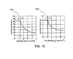
- the minimum sensing interval depends not only on temporal features such as primary traffic statistics, but also spatial features such as SU's average speed ⁇ n and primary density ⁇ p,i .
- the sensing interval plots 1001 and 1003 of FIG. 10 illustrate this behavior.
- Plot 1001 shows that, when an SU moves slowly (Region I ), the sensing interval will be determined by the PUs' traffic patterns, i.e., ⁇ idle , whereas when the SU moves more quickly (Region II ), the interval will be determined by the speed of SUs.
- Plot 1003 shows that, when PU density is low (Region I ), sensor mobility determines the sensing interval, and the interval is determines by primary traffic patterns when PU density increases (Region II ).
- the temporal features e.g., PUs' traffic patterns
- the spatial features e.g., sensor mobility and PU distribution
- this selection entails a tradeoff in exploring space and time domain spectrum opportunities. That is, a larger guard distance (thus enlarging the area of PPRs) will reduce the amount of spatial spectrum opportunities, while allowing mobile SUs to increase the sensing interval (see Eq. (13) increases spectrum opportunity in the temporal domain.
- Plot 1101 of FIG. 11 plots the spatio-temporal channel availability ⁇ i for various guard distances.
- ⁇ i is relatively small, ⁇ i suffers from a large sensing (temporal) overhead, whereas when ⁇ i is too large, spatial spectrum opportunity decreases considerably.
- ⁇ i too large ⁇ i decreases due to a large spatial overhead.
- u i can be approximated as u i ⁇ 1 - ⁇ ⁇ ⁇ T s , i ⁇ i .
- the channel availability in the spatio-temporal domain can be expressed as ⁇ i ( ⁇ i ) ⁇ i ( ⁇ i ) u i ( ⁇ i ), i.e., ⁇ i ⁇ i ⁇ e - f ⁇ i ⁇ 1 - ⁇ ⁇ ⁇ T s , i ⁇ i .
- the optimal guard distance increases as the average speed of the SUs increases. This implies that when SUs are highly mobile, it is preferable to increase the guard distance at the cost of reduced spatial spectrum opportunity, rather than reducing the sensing interval in the temporal domain.
- the total number of SUs in the network can be estimated as N ⁇ s A where A is the entire network area and ⁇ s is the average SU density.
- ] T where ⁇ i ⁇ p i 1.
- the total number of SUs selecting channel i in the network can be approximated as Np i .
- the probability that an arbitrarily chosen SU on channel i has m ⁇ interfering neighbors that have chosen the same channel follows a binomial distribution, i.e., M i ⁇ Bin ( m ; Np i -1, f i ).
- KKT Karush-Kuhn-Tucker
- the optimal channel selection strategy, p* is derived as described in the following proposition.
- the optimal channel selection probability becomes independent of the spatio-temporal spectrum opportunities ⁇ i , i.e., p i * ⁇ 1 K ⁇ i as N ⁇ ⁇ , where K is the number of licensed channels, and N the total number of SUs in the network.
- the optimal channel selection probability p* in Eq. (24) is affected by the SU density on each channel. This is due to the fact that as the SU density increases, the area of PPR needs to be enlarged, resulting in the reduced spatial spectrum opportunity.
- the performance of proposed algorithms was evaluated via both numerical and simulation study.
- the evaluation considered a CRN wherein mobile SUs coexist with PUs in a 5 ⁇ 5 km 2 area. It was assumed that there are 5 licensed channels and that the PU density on each channel is in the range of [0.12] ⁇ 10 -6 /m 2 and the average channel idle probability is in the range of [0.3 0.7], unless specified otherwise.
- channel index plot 1201 of FIG. 12 shows that the channel selection probability is higher for the channels with higher temporal availability, i.e., p i > p j when ⁇ idle,i > ⁇ idle,j .
- the three-dimensional plot 1301 of FIG. 13 shows the impact of heterogeneous PU density on channel selection probability.
- the plot 1301 shows that the channel selection probabilities differ depending on the PU density on each channel. The lower the PU density, the higher the channel selection probability. However, the PU density becomes less influential as the average secondary density increases, similar to the case in plot 1303 of FIG. 13 .
- the channel index plots 1401-1407 of FIG. 14 show the impact of average speed of SUs on the optimal channel selection strategy.
- SUs prefer to choose a channel with low PU density because high speed of SUs require a significant increase of guard distance ( ⁇ ) for primary protection (as can be seen in plot 1403 of FIG. 14 ), resulting in the PPRs on the channels with high PU density covering most of the network area.
- RAND random channel selection
- OPT-T temporal channel availability model
- OPT-ST optimal channel selection strategy with the proposed spatio-temporal channel availability model
- RAND random channel selection
- OPT-T optimal channel selection strategy only based on temporal channel availability model
- OPT-ST optimal channel selection strategy with the proposed spatio-temporal channel availability model
- the data plots 1501-1505 of FIG. 15 show the average and ⁇ 0.2 ⁇ interval of the achieved throughput and fairness of the testing schemes for various speeds of the SUs.
- the inventors ran simulations over 1600 randomly-generated topologies to study the average behavior.
- Plot 1501 of FIG. 15 shows that OPT-ST outperforms the other channel access strategies (i.e., OPT-T and RAND) under all simulated scenarios due to its ability to optimally select channels based on SUs mobility and the available spectrum opportunities in the spatio-temporal domains.
- Plot 1503 of FIG. 15 also shows that OPT-ST outperforms the other schemes in terms of fairness due to its ability to optimally select channels in such a way that the average lint throughput (or channel access time) is maximized.
- Plot 1505 of FIG. 15 shows the throughput performance of the testing schemes for various secondary density values.
- the plot 1505 shows that the throughput performance degrades as the SU density increase because of the increased level of channel access contention among SUs.
- the throughput performance improvement of OPT-ST over RAND decreases as the density increases. This is due to the fact that the optimal channel selection strategy will be independent of the channel availability (i.e., ⁇ s) in a dense network.
Landscapes
- Engineering & Computer Science (AREA)
- Computer Networks & Wireless Communication (AREA)
- Signal Processing (AREA)
- Mobile Radio Communication Systems (AREA)
Applications Claiming Priority (1)
| Application Number | Priority Date | Filing Date | Title |
|---|---|---|---|
| US12/894,663 US8351861B2 (en) | 2010-09-30 | 2010-09-30 | Opportunistic spectrum access in mobile cognitive radio networks |
Publications (2)
| Publication Number | Publication Date |
|---|---|
| EP2437533A1 true EP2437533A1 (de) | 2012-04-04 |
| EP2437533B1 EP2437533B1 (de) | 2017-03-08 |
Family
ID=44720511
Family Applications (1)
| Application Number | Title | Priority Date | Filing Date |
|---|---|---|---|
| EP11007875.5A Active EP2437533B1 (de) | 2010-09-30 | 2011-09-28 | Opportunistischer Spektrumszugang in mobilen kognitiven Funknetzwerken |
Country Status (2)
| Country | Link |
|---|---|
| US (1) | US8351861B2 (de) |
| EP (1) | EP2437533B1 (de) |
Cited By (4)
| Publication number | Priority date | Publication date | Assignee | Title |
|---|---|---|---|---|
| CN102869111A (zh) * | 2012-10-09 | 2013-01-09 | 南京大学 | 一种认知无线电中基于三态学习策略的机会频谱接入方法 |
| CN104365129A (zh) * | 2012-04-11 | 2015-02-18 | 英特尔公司 | 用于实施动态频带访问的多个无线电设备 |
| CN105338532A (zh) * | 2014-08-08 | 2016-02-17 | 普天信息技术有限公司 | 一种授权频点的认知方法及授权频点管理系统 |
| CN111262638A (zh) * | 2020-01-17 | 2020-06-09 | 合肥工业大学 | 基于高效样本学习的动态频谱接入方法 |
Families Citing this family (15)
| Publication number | Priority date | Publication date | Assignee | Title |
|---|---|---|---|---|
| FR2965993B1 (fr) * | 2010-10-08 | 2013-03-15 | Thales Sa | Procede et dispositif de transmission d'informations en contention sur des creneaux temporels entre des noeuds emetteurs-recepteurs d'un reseau ad hoc |
| US8488505B2 (en) * | 2011-02-02 | 2013-07-16 | College Of William And Mary | Method/system for conserving resources during conversation over wireless network transport media |
| JP5796325B2 (ja) | 2011-03-31 | 2015-10-21 | ソニー株式会社 | 通信制御装置、通信制御方法及び通信制御システム |
| US20130012138A1 (en) * | 2011-07-06 | 2013-01-10 | Qualcomm Incorporated | Method for improving robustness of spectrum sensing in presence of bursty interference |
| US9094836B2 (en) * | 2012-09-15 | 2015-07-28 | Electronics And Telecommunications Research Institute | Method for calculating fairness index and method for allocating resources based on the fairness index in coexistence management system |
| US8948038B1 (en) | 2012-12-10 | 2015-02-03 | Google Inc. | Augmenting spectrum sharing using network measurements |
| US9164820B1 (en) | 2013-05-30 | 2015-10-20 | Dell Software Inc. | System and method for correcting scrambled messages |
| WO2014193217A1 (en) | 2013-05-31 | 2014-12-04 | Mimos Berhad | A system and method for managing a cognitive radio network |
| US20150296386A1 (en) * | 2014-04-15 | 2015-10-15 | Eden Rock Communications, Llc | System and method for spectrum sharing |
| EP3226642A4 (de) * | 2014-11-27 | 2018-06-27 | LG Electronics Inc. | Direktzugriffsverfahren und vorrichtung dafür |
| CN112584388A (zh) | 2014-11-28 | 2021-03-30 | 索尼公司 | 用于无线通信系统的控制设备和控制方法、通信设备 |
| AU2015101185A4 (en) * | 2015-07-26 | 2015-10-08 | Macau University Of Science And Technology | Power control method for spectrum sharing cognitive radio network |
| CN107666720A (zh) * | 2016-07-29 | 2018-02-06 | 索尼公司 | 电子设备和用于电子设备的方法 |
| US10650621B1 (en) | 2016-09-13 | 2020-05-12 | Iocurrents, Inc. | Interfacing with a vehicular controller area network |
| US10813169B2 (en) | 2018-03-22 | 2020-10-20 | GoTenna, Inc. | Mesh network deployment kit |
Citations (3)
| Publication number | Priority date | Publication date | Assignee | Title |
|---|---|---|---|---|
| WO2009018300A1 (en) * | 2007-07-31 | 2009-02-05 | Motorola, Inc. | Method and apparatus for spectrum sharing between an incumbent communication system and a cognitive radio system |
| WO2009031825A2 (en) * | 2007-09-05 | 2009-03-12 | Electronics And Telecommunications Research Institute | Method and system for managing channel set for dynamic channel allocation |
| EP2205016A1 (de) * | 2009-01-06 | 2010-07-07 | Huawei Technologies Co., Ltd. | Verfahren und Vorrichtung für den Spektrumszugang von Sekundärbenutzern in einem kognitiven Funksystem |
Family Cites Families (4)
| Publication number | Priority date | Publication date | Assignee | Title |
|---|---|---|---|---|
| US8223699B2 (en) * | 2007-03-30 | 2012-07-17 | Motorola Solutions, Inc. | Method and apparatus for detecting and identifying spectrum opportunities |
| US8103217B2 (en) * | 2008-06-11 | 2012-01-24 | Samsung Electronics Co., Ltd. | Apparatus and method for radio communication |
| KR101491555B1 (ko) * | 2008-10-10 | 2015-02-11 | 삼성전자주식회사 | 특징 검출을 이용하여 충돌을 검사하는 인지 무선 통신 단말기 및 인지 무선 통신 방법 |
| US8660498B2 (en) * | 2009-06-29 | 2014-02-25 | Motorola Solutions, Inc. | Method for database driven channel quality estimation in a cognitive radio network |
-
2010
- 2010-09-30 US US12/894,663 patent/US8351861B2/en active Active
-
2011
- 2011-09-28 EP EP11007875.5A patent/EP2437533B1/de active Active
Patent Citations (3)
| Publication number | Priority date | Publication date | Assignee | Title |
|---|---|---|---|---|
| WO2009018300A1 (en) * | 2007-07-31 | 2009-02-05 | Motorola, Inc. | Method and apparatus for spectrum sharing between an incumbent communication system and a cognitive radio system |
| WO2009031825A2 (en) * | 2007-09-05 | 2009-03-12 | Electronics And Telecommunications Research Institute | Method and system for managing channel set for dynamic channel allocation |
| EP2205016A1 (de) * | 2009-01-06 | 2010-07-07 | Huawei Technologies Co., Ltd. | Verfahren und Vorrichtung für den Spektrumszugang von Sekundärbenutzern in einem kognitiven Funksystem |
Non-Patent Citations (2)
| Title |
|---|
| QING ZHAO ET AL: "Decentralized cognitive mac for dynamic spectrum access", 2005 1ST IEEE INTERNATIONAL SYMPOSIUM ON NEW FRONTIERS IN DYNAMIC SPECTRUM ACCESS NETWORKS, BALTIMORE, MD, USA, 8 November 2005 (2005-11-08), pages 224 - 232, XP010855119, ISBN: 978-1-4244-0013-3, DOI: 10.1109/DYSPAN.2005.1542638 * |
| QING ZHAO ET AL: "Decentralized cognitive MAC for opportunistic spectrum access in ad hoc networks: A POMDP framework", IEEE JOURNAL ON SELECTED AREAS IN COMMUNICATIONS, IEEE SERVICE CENTER, PISCATAWAY, US, vol. 25, no. 3, 1 April 2007 (2007-04-01), pages 589 - 600, XP011177058, ISSN: 0733-8716, DOI: 10.1109/JSAC.2007.070409 * |
Cited By (8)
| Publication number | Priority date | Publication date | Assignee | Title |
|---|---|---|---|---|
| CN104365129A (zh) * | 2012-04-11 | 2015-02-18 | 英特尔公司 | 用于实施动态频带访问的多个无线电设备 |
| CN104365129B (zh) * | 2012-04-11 | 2018-04-27 | 英特尔公司 | 用于实施动态频带访问的多个无线电设备 |
| CN102869111A (zh) * | 2012-10-09 | 2013-01-09 | 南京大学 | 一种认知无线电中基于三态学习策略的机会频谱接入方法 |
| CN102869111B (zh) * | 2012-10-09 | 2017-02-22 | 南京大学 | 一种认知无线电中基于三态学习策略的机会频谱接入方法 |
| CN105338532A (zh) * | 2014-08-08 | 2016-02-17 | 普天信息技术有限公司 | 一种授权频点的认知方法及授权频点管理系统 |
| CN105338532B (zh) * | 2014-08-08 | 2019-02-05 | 普天信息技术有限公司 | 一种授权频点的认知方法及授权频点管理系统 |
| CN111262638A (zh) * | 2020-01-17 | 2020-06-09 | 合肥工业大学 | 基于高效样本学习的动态频谱接入方法 |
| CN111262638B (zh) * | 2020-01-17 | 2021-09-24 | 合肥工业大学 | 基于高效样本学习的动态频谱接入方法 |
Also Published As
| Publication number | Publication date |
|---|---|
| US20120083303A1 (en) | 2012-04-05 |
| EP2437533B1 (de) | 2017-03-08 |
| US8351861B2 (en) | 2013-01-08 |
Similar Documents
| Publication | Publication Date | Title |
|---|---|---|
| EP2437533B1 (de) | Opportunistischer Spektrumszugang in mobilen kognitiven Funknetzwerken | |
| Liu et al. | Cooperative spectrum sensing optimization in energy-harvesting cognitive radio networks | |
| Yang et al. | Wireless coexistence between IEEE 802.11-and IEEE 802.15. 4-based networks: A survey | |
| Zhang et al. | Enabling coexistence of heterogeneous wireless systems: Case for ZigBee and WiFi | |
| Langendoen et al. | Analyzing MAC protocols for low data-rate applications | |
| Mesodiakaki et al. | Performance analysis of a cognitive radio contention-aware channel selection algorithm | |
| Lim et al. | Cognitive radio network in vehicular ad hoc network (VANET): A survey | |
| Chong et al. | An adaptive WLAN interference mitigation scheme for ZigBee sensor networks | |
| Rehmani et al. | Activity pattern impact of primary radio nodes on channel selection strategies | |
| Winter et al. | Wireless coexistence and spectrum sensing in industrial Internet of Things: An experimental study | |
| Zhang et al. | Optimization of MAC frame structure for opportunistic spectrum access | |
| Sun et al. | Cross-layer QoS optimization of wireless sensor network for smart grid | |
| Liu et al. | Throughput assurance of wireless body area networks coexistence based on stochastic geometry | |
| Ben Hamida et al. | On the complexity of an accurate and precise performance evaluation of wireless networks using simulations | |
| Bezunartea et al. | Impact of cross-layer interactions between radio duty cycling and routing on the efficiency of a wireless sensor network: A testbed study involving contikiMAC and RPL | |
| WO2013187753A2 (en) | System and method for dynamic spectrum access with coordinated primary user management | |
| Goratti et al. | An urn occupancy approach for cognitive radio networks in DTVB white spaces | |
| Guo et al. | Novel energy-efficient miner monitoring system with duty-cycled wireless sensor networks | |
| Watfa et al. | A battery-aware high-throughput MAC layer protocol in sensor networks | |
| Wang et al. | Modeling and parameter analysis of IEEE 802.15. 4-based networks and the metering application | |
| Zlobinsky et al. | Spectrum Sensing and SINR Estimation in an IEEE 802.11 s Dynamic Spectrum Access Wireless Mesh Network | |
| Šolc et al. | Whitelisting in RFDMA Networks | |
| Sun | Spectrum Sensing for Cognitive Radio Networks | |
| Mondal | Sensing-assisted spectrum access strategy and optimisation in cognitive radio networks | |
| Muppirisetty | Location-aware Communications |
Legal Events
| Date | Code | Title | Description |
|---|---|---|---|
| PUAI | Public reference made under article 153(3) epc to a published international application that has entered the european phase |
Free format text: ORIGINAL CODE: 0009012 |
|
| 17P | Request for examination filed |
Effective date: 20111027 |
|
| AK | Designated contracting states |
Kind code of ref document: A1 Designated state(s): AL AT BE BG CH CY CZ DE DK EE ES FI FR GB GR HR HU IE IS IT LI LT LU LV MC MK MT NL NO PL PT RO RS SE SI SK SM TR |
|
| AX | Request for extension of the european patent |
Extension state: BA ME |
|
| RIN1 | Information on inventor provided before grant (corrected) |
Inventor name: MIN, ALEXANDER Inventor name: KIM, KYU-HAN Inventor name: SINGH, JATINDER PAL |
|
| 17Q | First examination report despatched |
Effective date: 20130927 |
|
| RIC1 | Information provided on ipc code assigned before grant |
Ipc: H04W 74/08 20090101ALN20160727BHEP Ipc: H04W 16/14 20090101AFI20160727BHEP |
|
| RIC1 | Information provided on ipc code assigned before grant |
Ipc: H04W 74/08 20090101ALN20160729BHEP Ipc: H04W 16/14 20090101AFI20160729BHEP |
|
| GRAP | Despatch of communication of intention to grant a patent |
Free format text: ORIGINAL CODE: EPIDOSNIGR1 |
|
| INTG | Intention to grant announced |
Effective date: 20160929 |
|
| STAA | Information on the status of an ep patent application or granted ep patent |
Free format text: STATUS: GRANT OF PATENT IS INTENDED |
|
| GRAS | Grant fee paid |
Free format text: ORIGINAL CODE: EPIDOSNIGR3 |
|
| GRAA | (expected) grant |
Free format text: ORIGINAL CODE: 0009210 |
|
| STAA | Information on the status of an ep patent application or granted ep patent |
Free format text: STATUS: THE PATENT HAS BEEN GRANTED |
|
| AK | Designated contracting states |
Kind code of ref document: B1 Designated state(s): AL AT BE BG CH CY CZ DE DK EE ES FI FR GB GR HR HU IE IS IT LI LT LU LV MC MK MT NL NO PL PT RO RS SE SI SK SM TR |
|
| REG | Reference to a national code |
Ref country code: GB Ref legal event code: FG4D |
|
| REG | Reference to a national code |
Ref country code: CH Ref legal event code: EP Ref country code: AT Ref legal event code: REF Ref document number: 874531 Country of ref document: AT Kind code of ref document: T Effective date: 20170315 |
|
| REG | Reference to a national code |
Ref country code: IE Ref legal event code: FG4D |
|
| REG | Reference to a national code |
Ref country code: DE Ref legal event code: R096 Ref document number: 602011035619 Country of ref document: DE |
|
| REG | Reference to a national code |
Ref country code: LT Ref legal event code: MG4D |
|
| REG | Reference to a national code |
Ref country code: NL Ref legal event code: MP Effective date: 20170308 |
|
| PG25 | Lapsed in a contracting state [announced via postgrant information from national office to epo] |
Ref country code: GR Free format text: LAPSE BECAUSE OF FAILURE TO SUBMIT A TRANSLATION OF THE DESCRIPTION OR TO PAY THE FEE WITHIN THE PRESCRIBED TIME-LIMIT Effective date: 20170609 Ref country code: LT Free format text: LAPSE BECAUSE OF FAILURE TO SUBMIT A TRANSLATION OF THE DESCRIPTION OR TO PAY THE FEE WITHIN THE PRESCRIBED TIME-LIMIT Effective date: 20170308 Ref country code: NO Free format text: LAPSE BECAUSE OF FAILURE TO SUBMIT A TRANSLATION OF THE DESCRIPTION OR TO PAY THE FEE WITHIN THE PRESCRIBED TIME-LIMIT Effective date: 20170608 Ref country code: HR Free format text: LAPSE BECAUSE OF FAILURE TO SUBMIT A TRANSLATION OF THE DESCRIPTION OR TO PAY THE FEE WITHIN THE PRESCRIBED TIME-LIMIT Effective date: 20170308 Ref country code: FI Free format text: LAPSE BECAUSE OF FAILURE TO SUBMIT A TRANSLATION OF THE DESCRIPTION OR TO PAY THE FEE WITHIN THE PRESCRIBED TIME-LIMIT Effective date: 20170308 |
|
| REG | Reference to a national code |
Ref country code: AT Ref legal event code: MK05 Ref document number: 874531 Country of ref document: AT Kind code of ref document: T Effective date: 20170308 |
|
| PG25 | Lapsed in a contracting state [announced via postgrant information from national office to epo] |
Ref country code: LV Free format text: LAPSE BECAUSE OF FAILURE TO SUBMIT A TRANSLATION OF THE DESCRIPTION OR TO PAY THE FEE WITHIN THE PRESCRIBED TIME-LIMIT Effective date: 20170308 Ref country code: SE Free format text: LAPSE BECAUSE OF FAILURE TO SUBMIT A TRANSLATION OF THE DESCRIPTION OR TO PAY THE FEE WITHIN THE PRESCRIBED TIME-LIMIT Effective date: 20170308 Ref country code: ES Free format text: LAPSE BECAUSE OF FAILURE TO SUBMIT A TRANSLATION OF THE DESCRIPTION OR TO PAY THE FEE WITHIN THE PRESCRIBED TIME-LIMIT Effective date: 20170308 Ref country code: RS Free format text: LAPSE BECAUSE OF FAILURE TO SUBMIT A TRANSLATION OF THE DESCRIPTION OR TO PAY THE FEE WITHIN THE PRESCRIBED TIME-LIMIT Effective date: 20170308 Ref country code: BG Free format text: LAPSE BECAUSE OF FAILURE TO SUBMIT A TRANSLATION OF THE DESCRIPTION OR TO PAY THE FEE WITHIN THE PRESCRIBED TIME-LIMIT Effective date: 20170608 |
|
| REG | Reference to a national code |
Ref country code: FR Ref legal event code: PLFP Year of fee payment: 7 |
|
| PG25 | Lapsed in a contracting state [announced via postgrant information from national office to epo] |
Ref country code: NL Free format text: LAPSE BECAUSE OF FAILURE TO SUBMIT A TRANSLATION OF THE DESCRIPTION OR TO PAY THE FEE WITHIN THE PRESCRIBED TIME-LIMIT Effective date: 20170308 |
|
| PG25 | Lapsed in a contracting state [announced via postgrant information from national office to epo] |
Ref country code: AT Free format text: LAPSE BECAUSE OF FAILURE TO SUBMIT A TRANSLATION OF THE DESCRIPTION OR TO PAY THE FEE WITHIN THE PRESCRIBED TIME-LIMIT Effective date: 20170308 Ref country code: RO Free format text: LAPSE BECAUSE OF FAILURE TO SUBMIT A TRANSLATION OF THE DESCRIPTION OR TO PAY THE FEE WITHIN THE PRESCRIBED TIME-LIMIT Effective date: 20170308 Ref country code: EE Free format text: LAPSE BECAUSE OF FAILURE TO SUBMIT A TRANSLATION OF THE DESCRIPTION OR TO PAY THE FEE WITHIN THE PRESCRIBED TIME-LIMIT Effective date: 20170308 Ref country code: CZ Free format text: LAPSE BECAUSE OF FAILURE TO SUBMIT A TRANSLATION OF THE DESCRIPTION OR TO PAY THE FEE WITHIN THE PRESCRIBED TIME-LIMIT Effective date: 20170308 Ref country code: SK Free format text: LAPSE BECAUSE OF FAILURE TO SUBMIT A TRANSLATION OF THE DESCRIPTION OR TO PAY THE FEE WITHIN THE PRESCRIBED TIME-LIMIT Effective date: 20170308 Ref country code: IT Free format text: LAPSE BECAUSE OF FAILURE TO SUBMIT A TRANSLATION OF THE DESCRIPTION OR TO PAY THE FEE WITHIN THE PRESCRIBED TIME-LIMIT Effective date: 20170308 |
|
| PG25 | Lapsed in a contracting state [announced via postgrant information from national office to epo] |
Ref country code: PT Free format text: LAPSE BECAUSE OF FAILURE TO SUBMIT A TRANSLATION OF THE DESCRIPTION OR TO PAY THE FEE WITHIN THE PRESCRIBED TIME-LIMIT Effective date: 20170710 Ref country code: SM Free format text: LAPSE BECAUSE OF FAILURE TO SUBMIT A TRANSLATION OF THE DESCRIPTION OR TO PAY THE FEE WITHIN THE PRESCRIBED TIME-LIMIT Effective date: 20170308 Ref country code: PL Free format text: LAPSE BECAUSE OF FAILURE TO SUBMIT A TRANSLATION OF THE DESCRIPTION OR TO PAY THE FEE WITHIN THE PRESCRIBED TIME-LIMIT Effective date: 20170308 Ref country code: IS Free format text: LAPSE BECAUSE OF FAILURE TO SUBMIT A TRANSLATION OF THE DESCRIPTION OR TO PAY THE FEE WITHIN THE PRESCRIBED TIME-LIMIT Effective date: 20170708 |
|
| REG | Reference to a national code |
Ref country code: DE Ref legal event code: R097 Ref document number: 602011035619 Country of ref document: DE |
|
| PLBE | No opposition filed within time limit |
Free format text: ORIGINAL CODE: 0009261 |
|
| STAA | Information on the status of an ep patent application or granted ep patent |
Free format text: STATUS: NO OPPOSITION FILED WITHIN TIME LIMIT |
|
| PG25 | Lapsed in a contracting state [announced via postgrant information from national office to epo] |
Ref country code: DK Free format text: LAPSE BECAUSE OF FAILURE TO SUBMIT A TRANSLATION OF THE DESCRIPTION OR TO PAY THE FEE WITHIN THE PRESCRIBED TIME-LIMIT Effective date: 20170308 |
|
| 26N | No opposition filed |
Effective date: 20171211 |
|
| PG25 | Lapsed in a contracting state [announced via postgrant information from national office to epo] |
Ref country code: SI Free format text: LAPSE BECAUSE OF FAILURE TO SUBMIT A TRANSLATION OF THE DESCRIPTION OR TO PAY THE FEE WITHIN THE PRESCRIBED TIME-LIMIT Effective date: 20170308 |
|
| REG | Reference to a national code |
Ref country code: CH Ref legal event code: PL |
|
| PG25 | Lapsed in a contracting state [announced via postgrant information from national office to epo] |
Ref country code: MC Free format text: LAPSE BECAUSE OF FAILURE TO SUBMIT A TRANSLATION OF THE DESCRIPTION OR TO PAY THE FEE WITHIN THE PRESCRIBED TIME-LIMIT Effective date: 20170308 |
|
| REG | Reference to a national code |
Ref country code: IE Ref legal event code: MM4A |
|
| REG | Reference to a national code |
Ref country code: BE Ref legal event code: MM Effective date: 20170930 |
|
| PG25 | Lapsed in a contracting state [announced via postgrant information from national office to epo] |
Ref country code: LU Free format text: LAPSE BECAUSE OF NON-PAYMENT OF DUE FEES Effective date: 20170928 |
|
| PG25 | Lapsed in a contracting state [announced via postgrant information from national office to epo] |
Ref country code: LI Free format text: LAPSE BECAUSE OF NON-PAYMENT OF DUE FEES Effective date: 20170930 Ref country code: CH Free format text: LAPSE BECAUSE OF NON-PAYMENT OF DUE FEES Effective date: 20170930 Ref country code: IE Free format text: LAPSE BECAUSE OF NON-PAYMENT OF DUE FEES Effective date: 20170928 |
|
| PG25 | Lapsed in a contracting state [announced via postgrant information from national office to epo] |
Ref country code: BE Free format text: LAPSE BECAUSE OF NON-PAYMENT OF DUE FEES Effective date: 20170930 |
|
| REG | Reference to a national code |
Ref country code: FR Ref legal event code: PLFP Year of fee payment: 8 |
|
| PG25 | Lapsed in a contracting state [announced via postgrant information from national office to epo] |
Ref country code: MT Free format text: LAPSE BECAUSE OF NON-PAYMENT OF DUE FEES Effective date: 20170928 |
|
| PG25 | Lapsed in a contracting state [announced via postgrant information from national office to epo] |
Ref country code: HU Free format text: LAPSE BECAUSE OF FAILURE TO SUBMIT A TRANSLATION OF THE DESCRIPTION OR TO PAY THE FEE WITHIN THE PRESCRIBED TIME-LIMIT; INVALID AB INITIO Effective date: 20110928 |
|
| PG25 | Lapsed in a contracting state [announced via postgrant information from national office to epo] |
Ref country code: CY Free format text: LAPSE BECAUSE OF NON-PAYMENT OF DUE FEES Effective date: 20170308 |
|
| PG25 | Lapsed in a contracting state [announced via postgrant information from national office to epo] |
Ref country code: MK Free format text: LAPSE BECAUSE OF FAILURE TO SUBMIT A TRANSLATION OF THE DESCRIPTION OR TO PAY THE FEE WITHIN THE PRESCRIBED TIME-LIMIT Effective date: 20170308 |
|
| PG25 | Lapsed in a contracting state [announced via postgrant information from national office to epo] |
Ref country code: TR Free format text: LAPSE BECAUSE OF FAILURE TO SUBMIT A TRANSLATION OF THE DESCRIPTION OR TO PAY THE FEE WITHIN THE PRESCRIBED TIME-LIMIT Effective date: 20170308 |
|
| PG25 | Lapsed in a contracting state [announced via postgrant information from national office to epo] |
Ref country code: AL Free format text: LAPSE BECAUSE OF FAILURE TO SUBMIT A TRANSLATION OF THE DESCRIPTION OR TO PAY THE FEE WITHIN THE PRESCRIBED TIME-LIMIT Effective date: 20170308 |
|
| PGFP | Annual fee paid to national office [announced via postgrant information from national office to epo] |
Ref country code: GB Payment date: 20230921 Year of fee payment: 13 |
|
| PGFP | Annual fee paid to national office [announced via postgrant information from national office to epo] |
Ref country code: FR Payment date: 20230918 Year of fee payment: 13 Ref country code: DE Payment date: 20230919 Year of fee payment: 13 |