EP2437234B1 - Système et procédé d'indication de proximité du sol avec suivi de vision - Google Patents
Système et procédé d'indication de proximité du sol avec suivi de vision Download PDFInfo
- Publication number
- EP2437234B1 EP2437234B1 EP11183156.6A EP11183156A EP2437234B1 EP 2437234 B1 EP2437234 B1 EP 2437234B1 EP 11183156 A EP11183156 A EP 11183156A EP 2437234 B1 EP2437234 B1 EP 2437234B1
- Authority
- EP
- European Patent Office
- Prior art keywords
- boundaries
- obstacle
- path
- display
- determining
- Prior art date
- Legal status (The legal status is an assumption and is not a legal conclusion. Google has not performed a legal analysis and makes no representation as to the accuracy of the status listed.)
- Active
Links
- 238000000034 method Methods 0.000 title claims description 21
- 230000004044 response Effects 0.000 claims description 17
- 238000013459 approach Methods 0.000 claims description 7
- 230000001360 synchronised effect Effects 0.000 claims description 2
- 230000000007 visual effect Effects 0.000 description 14
- 210000003128 head Anatomy 0.000 description 11
- 230000008859 change Effects 0.000 description 7
- 230000006870 function Effects 0.000 description 7
- 238000012545 processing Methods 0.000 description 7
- 238000004891 communication Methods 0.000 description 4
- 238000010586 diagram Methods 0.000 description 3
- 239000004973 liquid crystal related substance Substances 0.000 description 3
- 230000008569 process Effects 0.000 description 3
- 230000009471 action Effects 0.000 description 2
- 238000005516 engineering process Methods 0.000 description 2
- 238000007726 management method Methods 0.000 description 2
- 238000012544 monitoring process Methods 0.000 description 2
- 230000037361 pathway Effects 0.000 description 2
- 230000001960 triggered effect Effects 0.000 description 2
- 235000004522 Pentaglottis sempervirens Nutrition 0.000 description 1
- XUIMIQQOPSSXEZ-UHFFFAOYSA-N Silicon Chemical compound [Si] XUIMIQQOPSSXEZ-UHFFFAOYSA-N 0.000 description 1
- 230000003044 adaptive effect Effects 0.000 description 1
- 238000010276 construction Methods 0.000 description 1
- 238000007796 conventional method Methods 0.000 description 1
- 230000008878 coupling Effects 0.000 description 1
- 238000010168 coupling process Methods 0.000 description 1
- 238000005859 coupling reaction Methods 0.000 description 1
- 230000003247 decreasing effect Effects 0.000 description 1
- 238000001514 detection method Methods 0.000 description 1
- 206010013395 disorientation Diseases 0.000 description 1
- 238000003384 imaging method Methods 0.000 description 1
- 230000000977 initiatory effect Effects 0.000 description 1
- 239000011159 matrix material Substances 0.000 description 1
- 230000003287 optical effect Effects 0.000 description 1
- 238000009877 rendering Methods 0.000 description 1
- 229910052710 silicon Inorganic materials 0.000 description 1
- 239000010703 silicon Substances 0.000 description 1
- 239000013589 supplement Substances 0.000 description 1
- 239000010409 thin film Substances 0.000 description 1
Images


Classifications
-
- G—PHYSICS
- G08—SIGNALLING
- G08G—TRAFFIC CONTROL SYSTEMS
- G08G5/00—Traffic control systems for aircraft, e.g. air-traffic control [ATC]
- G08G5/0017—Arrangements for implementing traffic-related aircraft activities, e.g. arrangements for generating, displaying, acquiring or managing traffic information
- G08G5/0021—Arrangements for implementing traffic-related aircraft activities, e.g. arrangements for generating, displaying, acquiring or managing traffic information located in the aircraft
-
- G—PHYSICS
- G02—OPTICS
- G02B—OPTICAL ELEMENTS, SYSTEMS OR APPARATUS
- G02B27/00—Optical systems or apparatus not provided for by any of the groups G02B1/00 - G02B26/00, G02B30/00
- G02B27/0093—Optical systems or apparatus not provided for by any of the groups G02B1/00 - G02B26/00, G02B30/00 with means for monitoring data relating to the user, e.g. head-tracking, eye-tracking
-
- G—PHYSICS
- G02—OPTICS
- G02B—OPTICAL ELEMENTS, SYSTEMS OR APPARATUS
- G02B27/00—Optical systems or apparatus not provided for by any of the groups G02B1/00 - G02B26/00, G02B30/00
- G02B27/01—Head-up displays
-
- G—PHYSICS
- G08—SIGNALLING
- G08G—TRAFFIC CONTROL SYSTEMS
- G08G5/00—Traffic control systems for aircraft, e.g. air-traffic control [ATC]
- G08G5/06—Traffic control systems for aircraft, e.g. air-traffic control [ATC] for control when on the ground
- G08G5/065—Navigation or guidance aids, e.g. for taxiing or rolling
-
- G—PHYSICS
- G02—OPTICS
- G02B—OPTICAL ELEMENTS, SYSTEMS OR APPARATUS
- G02B27/00—Optical systems or apparatus not provided for by any of the groups G02B1/00 - G02B26/00, G02B30/00
- G02B27/01—Head-up displays
- G02B27/0101—Head-up displays characterised by optical features
- G02B2027/0138—Head-up displays characterised by optical features comprising image capture systems, e.g. camera
-
- G—PHYSICS
- G02—OPTICS
- G02B—OPTICAL ELEMENTS, SYSTEMS OR APPARATUS
- G02B27/00—Optical systems or apparatus not provided for by any of the groups G02B1/00 - G02B26/00, G02B30/00
- G02B27/01—Head-up displays
- G02B27/0101—Head-up displays characterised by optical features
- G02B2027/014—Head-up displays characterised by optical features comprising information/image processing systems
Definitions
- the exemplary embodiments described herein generally relate to aircraft ground operations and more particularly to displaying conformal taxiways and obstacles to a pilot of a taxiing aircraft.
- NTE near-to-eye
- HWD head worn display
- the NTE display is semi-transparent (such as a liquid crystal display (LCD), liquid crystal on silicon (LCos) display, or organic light emitting diode (OLED) display) so that the information presented on the NTE display appears to the user superimposed on the visible scene.
- a NTE display can provide a three-dimensional view of a scene outside the vehicle for use by the vehicle's operator even in poor visibility conditions, such as thick fog conditions.
- a method and apparatus are provided for displaying obstacles to an operator of a vehicle while moving along a path.
- the apparatus comprises a near-to-eye (NTE) display device that allows an operator of the vehicle to see an obstacle on, including the conformal edges of, a pathway of the vehicle.
- NTE near-to-eye
- a method of presenting an obstacle on a near-to-eye display to an operator of a vehicle comprises determining a path on which the vehicle may travel; determining a location of the vehicle on the path; determining a location of the obstacle on the path; and displaying a graphical representation of the path and the obstacle on the near-to-eye system.
- a method of displaying a taxiway and an obstacle on a near-to-eye display to a pilot of an aircraft comprises obtaining dimensions of the taxiway on which the aircraft is taxing, the taxiway defined by boundaries; determining the position of the aircraft on the taxiway; displaying the taxiway including the boundaries on the near-to-eye system worn by the pilot; providing a real time video from an infrared camera positioned on the aircraft and focused to display the taxiway or runway for identifying an obstacle, the infrared camera being synced to the direction of the gaze of the pilot as determined by the near-to-eye system; and displaying the obstacle on the near-to-eye system
- a system for viewing boundaries of a taxiway on which an aircraft is taxing comprises a near-to-eye display configured to be positioned adjacent an eye of a pilot of the aircraft; a flight management system configured to provide dimensions of the taxiway; a navigation system configured to determine the location of the aircraft on the taxiway; and a controller configured to provide, in response to the dimensions of the taxiway and the location of the aircraft, data including boundaries of the taxiway to the near-to-eye display for display thereon.
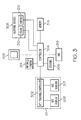
- FIG. 1 is a functional block diagram of a flight display system
- FIG. 2 is an exemplary embodiment of a near-to-eye display system
- FIG. 3 is a functional block diagram of the near-to-eye display system of FIG. 2 ;
- FIG. 4 is an exemplary view from an aircraft of the birds eye view ahead
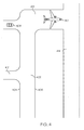
- FIG. 5 is an exemplary view on the conformal near-to-eye display of the view of FIG. 4 ;
- FIG. 6 is a flow chart in accordance with an exemplary embodiment.
- FIG. 7 is a flow chart in accordance with another exemplary embodiment.
- the exemplary embodiments described herein include a near-to-eye (NTE) display device that allows the pilot of an aircraft to see an obstacle on, including the conformal edges of, the runway or taxiway.
- NTE head tracking system provides a left to right range of motion, for example, 180 degrees, for visual scanning. Graphics generated for display tracks to the pilot's eye gaze.
- Input from a gimbaled head tracking Infrared camera gives the pilot the ability to scan the runway/taxiway for obstructions.
- a pixel to pixel linear interpolation of the video input will provide a movement and direction of a possible obstruction relative to the aircraft, thereby alerting the pilot to the hazard.
- the airport runway/taxiway information may be provided by the aircraft flight management system (FMS).
- FMS flight management system
- the aircraft's position may be determined from a global positioning system (GPS) or other sensors. While the system continually processes the runway/taxiway edges and obstacles, the presentation on the NTE display optionally may be initiated only when the need is determined.
- GPS global positioning system
- an embodiment of a system or a component may employ various integrated circuit components, e.g., memory elements, digital signal processing elements, logic elements, look-up tables, or the like, which may carry out a variety of functions under the control of one or more microprocessors or other control devices.
- integrated circuit components e.g., memory elements, digital signal processing elements, logic elements, look-up tables, or the like, which may carry out a variety of functions under the control of one or more microprocessors or other control devices.
- a flight deck display system 100 includes a user interface 102, a processor 104, one or more terrain databases 106 (including runway and taxiway information), one or more navigation databases 108, sensors 112, external data sources 114, and one or more display devices 116 (including the NTE system 117 subsequently discussed in more detail).
- the user interface 102 is in operable communication with the processor 104 and is configured to receive input from a user 109 (e.g., a pilot) and, in response to the user input, supplies command signals to the processor 104.
- the user interface 102 may be any one, or combination, of various known user interface devices including, but not limited to, one or more buttons, switches, knobs, and touch panels (not shown).
- the processor 104 may be implemented or realized with a general purpose processor, a content addressable memory, a digital signal processor, an application specific integrated circuit, a field programmable gate array, any suitable programmable logic device, discrete gate or transistor logic, discrete hardware components, or any combination designed to perform the functions described herein.
- a processor device may be realized as a microprocessor, a controller, a microcontroller, or a state machine.
- a processor device may be implemented as a combination of computing devices, e.g., a combination of a digital signal processor and a microprocessor, a plurality of microprocessors, one or more microprocessors in conjunction with a digital signal processor core, or any other such configuration.
- the processor 104 includes on-board RAM (random access memory) 103, and on-board ROM (read-only memory) 105.
- the program instructions that control the processor 104 may be stored in either or both the RAM 103 and the ROM 105.
- the operating system software may be stored in the ROM 105
- various operating mode software routines and various operational parameters may be stored in the RAM 103.
- the software executing the exemplary embodiment is stored in either the ROM 105 or the RAM 103. It will be appreciated that this is merely exemplary of one scheme for storing operating system software and software routines, and that various other storage schemes may be implemented.
- the memory 103, 105 may be realized as RAM memory, flash memory, EPROM memory, EEPROM memory, registers, a hard disk, a removable disk, a CD-ROM, or any other form of storage medium known in the art.
- the memory 103, 105 can be coupled to the processor 104 such that the processor 104 can read information from, and write information to, the memory 103, 105.
- the memory 103, 105 may be integral to the processor 104.
- the processor 104 and the memory 103, 105 may reside in an ASIC.
- a functional or logical module/component of the display system 100 might be realized using program code that is maintained in the memory 103, 105.
- the memory 103, 105 can be used to store data utilized to support the operation of the display system 100, as will become apparent from the following description.
- the processor 104 is in operable communication with the terrain databases 106, the navigation databases 108, and the display devices 116, and is coupled to receive various types of inertial data from the sensors 112, and various other avionics-related data from the external data sources 114.
- the processor 104 is configured, in response to the inertial data and the avionics-related data, to selectively retrieve terrain data from one or more of the terrain databases 106 and navigation data from one or more of the navigation databases 108, and to supply appropriate display commands to the display devices 116.
- the display devices 116 in response to the display commands, selectively render various types of textual, graphic, and/or iconic information.
- the terrain databases 106 include various types of data representative of the taxiways and runways over which the aircraft is taxing, and the navigation databases 108 include various types of navigation-related data.
- the sensors 112 may be implemented using various types of inertial sensors, systems, and or subsystems, now known or developed in the future, for supplying various types of inertial data, for example, representative of the state of the aircraft including aircraft speed, heading, altitude, and attitude.
- the sensors 112 include an Infrared camera.
- the other avionics receivers 118 include, for example, an ILS receiver and a GPS receiver.
- the ILS receiver provides aircraft with horizontal (or localizer) and vertical (or glide slope) guidance just before and during landing and, at certain fixed points, indicates the distance to the reference point of landing on a particular runway.
- the ILS receiver may also give ground position.
- the GPS receiver is a multi-channel receiver, with each channel tuned to receive one or more of the GPS broadcast signals transmitted by the constellation of GPS satellites (not illustrated) orbiting the earth.
- the display devices 116 in response to display commands supplied from the processor 104, selectively render various textual, graphic, and/or iconic information, and thereby supply visual feedback to the user 109.
- the display device 116 may be implemented using any one of numerous known display devices suitable for rendering textual, graphic, and/or iconic information in a format viewable by the user 109.
- Non-limiting examples of such display devices include various flat panel displays such as various types of LCD (liquid crystal display), TFT (thin film transistor) displays, and projection display LCD light engines.
- the display devices 116 may additionally be implemented as a panel mounted display, or any one of numerous known technologies.
- the display devices 116 include a near-to-eye (NTE) display system 117.
- NTE near-to-eye
- the preferred exemplary embodiment described in U. S. Patent Application 12/707,293 and shown in FIG. 2 , includes the operator 109 of a vehicle, such as a flight crew member of an aircraft, wearing a near-to-eye (NTE) display system 117.
- the NTE display system 117 includes a headband 206 coupled to a semi-transparent display 208 such that when correctly worn by the operator 109, the semi-transparent display 208 is placed in the line of sight of the right eye 210 at a predetermined distance from the right eye 210.
- LEDs 214 are located on a portion 212 of the headband 206 to sense a direction of gaze of the operator 109 (e.g. looking up, looking down, looking at one portion of a cockpit or another portion, etc.) at any point in time in order to present appropriate information on the display 208.
- the LEDs 214 are utilized to provide more detailed information about the state and actions of the operator 109.
- the NTE display system 117 is configured to monitor the head position of operator 109 by monitoring the position and orientation of the NTE display device (i.e., the NTE display system 117). In this manner, the operator's direction of gaze at any point in time can be sensed for generation and presentation of an appropriate transparent view including conformal graphics and/or other information on the display 208.
- the configuration of the NTE display system 117 is not limited to the device shown in FIG. 2 .
- the NTE display system 117 is a monocular NTE display system
- a binocular NTE display system could also be employed in the present embodiment.
- the monocular NTE display system 117 in accordance with the present embodiment has the display 208 situated over the right eye 210
- the present embodiment could also use a monocular NTE display system having the display positioned in the line of sight of the left eye 220.
- the LEDs 214 are incorporated in the portion 212 of the headband 206, the number and location of the LEDs 214 can be anywhere on the headband 206, such as in portion 222 or portion 224, or even located around the display 214.
- the LEDs 214 are infrared in order to emit wavelengths not visible to the operator 109 and thereby not interfere with operation of the aircraft and/or the view of the operator 109.
- the LEDs 214 are positioned on the headband 206 to allow sensing of the position and orientation of the NTE display system 117.
- the present embodiment is not limited to the use of infrared LEDs or, in fact, is not limited to the use of LEDs 214, and may include any reflective or emissive device attachable to the NTE display system 117 that would allow sensing of the position and orientation of the NTE display system 117 and, consequently, determination of the direction of gaze or focus of the pilot.
- FIG. 3 depicts a block diagram of a system 300 for aircraft operation in accordance with the present embodiment.
- the NTE display system 117 includes an NTE display 208, the NTE sensors 301 and a NTE tracking controller 302.
- the NTE tracking controller 302 receives signals from the NTE sensors 301, such as cockpit cameras (not shown) or infrared sensors 214, and generates signals which are provided to the display 208.
- the signals present appropriate information on the display 208 for generating the view of conformal graphics or other information for presentation to the operator 109.
- the NTE tracking controller 302 also generates focus data corresponding to the direction of gaze of the operator 109 in response to the information monitored by the NTE sensors 301, for example, whether the operator 109 is looking out the window (not shown) and in which direction, at the in-cockpit displays 306, or at some other point of interest.
- the NTE tracking controller 302 is coupled to a controller 304 for providing the focus data corresponding to the direction of gaze of the operator 109 thereto.
- the focus data (e.g., the operator head tracking data resulting from monitoring the position and orientation of the NTE display system 117) is utilized by the controller 304 for several purposes.
- the focus data is used for initiating a change in system operation and/or adaptive operation of cockpit alerting devices.
- Additional avionics sensors 306 are coupled to the controller 304 and when triggered, initiate a change in system operation or provide operator sensible alerts to the flight crew.
- a change in system operation may include changing the information and or visual presentation on one of the display monitors 306 or moving a visual presentation of flight information from one of the display monitors 306 to another one of the display monitors 306.
- the controller 304 may initiate such change in system operation in response to the focus data corresponding to the direction of gaze of the operator 109 received from the NTE controller 302.
- data representative of the dimensions and location of the taxiway (and optionally the runway), and specifically its boundaries, on which the aircraft is taxiing are provided to the processor 104 and the NTE tracking controller 302 from the terrain database 106.
- the location of the aircraft is determined, preferably by GPS coordinates obtained from the GPS receiver 118.
- the data provided by the processor 104 is converted to a video for presentation on the NTE display 208.
- an Infrared camera 314 is positioned on the aircraft for imaging any obstacles in its view within taxiing distance of the aircraft.
- the forward looking Infrared camera 314 can operate in any one of three modes. It may display the images as Infrared images in a first mode of operation, being gimbaled to the pilot's glaze by the NTE display system 117. In this first mode, the Infrared camera 314 preferably can rotate about 180 degrees, 90 degrees to either direction from the nose of the aircraft and in a plane with the taxiway, and is coupled to the NTE controller 302 (through the controller 304) for displaying the video taken by the Infrared camera 314 on the NTE display 208.
- a second mode it can operate in a graphics processing mode where the image is shown only as a threat circle with a center dot.
- the center dot becomes a line indicting a direction when the pixel to pixel interpolation algorithm detects a movement.
- the threat circle can grow in size when approached by the aircraft.
- it can supplement the conformal edges of the runway (or taxiway) by graphic processing the runway light's position and subtract that known distance from the conformal edge of the runway (or taxiway). In this mode the image is not shown, but the light intensity and position is processed to aid in the positioning of the conformal edges of the runway (or taxiway).
- a similar mode of graphic processing can be applied to the reflective center line of the runway (or taxiway).
- FIG. 4 a bird's eye view of the actual environment ahead of the aircraft is shown.
- an image (video) of the taxiway 402 and optionally other taxiways 412 or the runway 414 are presented on the NTE display 208 ( FIG. 5 ).
- the boundaries 404, 406 of the displayed taxiway 402, and an obstacle when present, for example a truck 408 or another aircraft 410 when present, are highlighted in some manner on the conformal NTE display.
- the boundaries 404, 406 and obstacle 408, 410 may be of a different format than other items displayed, for example, brighter, a different color, or thicker.
- the presentation on the conformal NTE display includes the taxiway 502, boundaries 504, 506 of the taxiway 502, taxiway 512, runway 514, truck 508, and aircraft 510.
- Obstacles such as the truck 508 and aircraft 510, are, for example, shown as a threat circle.
- An arrow protruding from the circles 508, 510 indicates any movement of the obstacle 508, 510.
- the truck 508 is moving to the left away from the taxiway 502 and the aircraft 510 is moving towards/onto the runway 514.
- the boundaries 404, 406 of the taxiway 402 and/or the obstacle 408, 410 may be displayed only when the processor 104 has determined they present a hazard. An alert by one of the alerting devices 308 may be initiated at that time.
- Operator sensible alerts are alerts that can be sensed by an operator, such as visual or audible alerts. Since the focus data indicates where the pilot's head (and potentially direction of gaze) are pointed, the controller 304 decides where and/or how to present an alert to warn the operator 109 of a condition requiring attention such as the approach to an obstacle or taxiway boundaries. Therefore, when the avionics sensors 306 are triggered, an alert signal is provided to the controller 304. The controller 304 then activates one or more of several cockpit alerting devices 308 selected in response to the focus data corresponding to the direction of gaze of the operator 109.
- the cockpit alerting devices 308 may include visual alerting devices 310 and audible alerting devices 312 in one or more areas of the cockpit.
- the controller 304 determines whether to provide the alert signal to one of the visual alerting devices 310 and/or one of the audible alerting devices 312 in response to the approach to an obstacle or taxiway boundaries by selecting between the visual alerting devices 310 and the audible alerting devices 312 in response to the focus data received from the NTE tracking controller 302. Accordingly, a visual alert could be repositioned from one of the visual alerting devices 310 to another one of the visual alerting devices 310 within the direction of focus or gaze of the operator 109 or to the NTE display 208 as determined by the focus data.
- the controller 304 may decide to present an audible tone from one of the audible alerting devices 312 rather than a flashing light from a visual alerting device 310 or the NTE display 208 to warn the operator 109 of a condition requiring an action by the pilot 109.
- the controller 304 may determine to provide the alert signal to the operator 109 by providing signals to the head down display 306 to present an alert message on the head down display 306 in response to the focus data received from the NTE tracking controller 302.
- the operator 109 could be directed to look outside the cockpit by a message and/or instructions on the head down display 306.
- the alert message on the head down display 306 could be a specific alphanumeric message or could be a change of the visual presentation or any portion thereof, such as a change of the background, a change of the color, or a flashing of the visual presentation.
- the NTE tracking controller 302 for determining the focus (direction) of the operator 109 and the controller 304 for controlling the alert operation of the aircraft are depicted as two separate controllers. For distributed operation, separate controllers would be appropriate. However, the present embodiment is not limited to such distributed computing and those skilled in the art will realize that both determining the focus of the operator 109 and controlling the alert operation of the aircraft could be implemented in a single controller.
- FIGS. 6 and 7 are flow charts that illustrate exemplary embodiments 600, 700 of a NTE display system 117 for presenting obstacles, including pathway boundaries, suitable for use with moving vehicles.
- the various tasks performed in connection with the embodiments 600, 700 may be performed by software, hardware, firmware, or any combination thereof.
- the following description may refer to elements mentioned above in connection with FIGS. 1-3 .
- portions may be performed by different elements of the described system, e.g., a processor, a display element, or a data communication component.
- the embodiments 600, 700 may include any number of additional or alternative tasks, the tasks shown in FIGS.
- embodiments 600, 700 may be incorporated into a more comprehensive procedure or process having additional functionality not described in detail herein. Moreover, one or more of the tasks shown in FIGS. 6 and 7 could be omitted from the embodiment 600, 700 as long as the intended overall functionality remains intact.
- the exemplary embodiment 600 of FIG. 6 includes determining 602 a path on which a vehicle is traveling, determining 604 the location of the vehicle on the path, determining 606 the location of an obstacle on the path, and displaying 608 a graphical representation of the path and the obstacle on a near-to-eye system worn by an operator of the vehicle.
- the exemplary embodiment 700 of FIG. 7 includes obtaining 702 dimensions of a taxiway on which an aircraft is traveling, the taxiway being defined by boundaries, determining 704 the position of the aircraft on the taxiway, displaying 706 the taxiway including the boundaries on a near-to-eye system worn by a pilot of the aircraft, providing 708 a real time video from an infrared camera on the aircraft of the taxiway for identifying an obstacle, the infrared camera being synchronized to the detection of the gaze of the pilot as determined by the near-to-eye system, and displaying 710 the obstacle on the near-to-eye system.
Landscapes
- Physics & Mathematics (AREA)
- General Physics & Mathematics (AREA)
- Engineering & Computer Science (AREA)
- Aviation & Aerospace Engineering (AREA)
- Optics & Photonics (AREA)
- Radar, Positioning & Navigation (AREA)
- Remote Sensing (AREA)
- Traffic Control Systems (AREA)
Claims (14)
- Procédé de présentation d'un obstacle sur un affichage proche de l'oeil à un opérateur d'un véhicule, comprenant les étapes suivantes :déterminer (602) une voie sur lequel le véhicule peut circuler ;déterminer (604) un emplacement du véhicule sur la voie ;fournir une vidéo en temps réel de la voie depuis le véhicule ;déterminer (606) un emplacement de l'obstacle sur la voie ; etafficher (608) une représentation graphique conforme de la voie et de l'obstacle sur le système proche de l'oeil ;caractérisé par les étapes suivantes :effectuer une interpolation linéaire pixel à pixel de la vidéo ; etafficher une indication du mouvement de l'obstacle affiché en réponse à l'interpolation linéaire pixel à pixel.
- Procédé selon la revendication 1, dans lequel la détermination d'un emplacement de l'obstacle comprend de :déterminer les limites de la voie ; etoù l'étape d'affichage comprend :d'afficher les limites conformes de la voie.
- Procédé selon la revendication 1, dans lequel la détermination d'un emplacement de l'obstacle comprend de :délivrer sur l'affichage proche de l'oeil une vidéo infrarouge prise par une caméra positionnée sur le véhicule.
- Procédé selon la revendication 3, comprenant les étapes suivantes :déterminer une direction du regard de l'opérateur en réponse à l'orientation de l'affichage proche de l'oeil, etoù la détermination d'un emplacement de l'obstacle comprend de délivrer la vidéo infrarouge par la caméra ayant une direction synchronisée avec la direction du regard de l'opérateur.
- Procédé selon la revendication 2, comprenant en outre l'étape suivante :déterminer les limites de la voie en soustrayant une distance d'une pluralité de lumières délimitant la voie.
- Procédé selon la revendication 2, comprenant en outre l'étape suivante :déterminer les limites de la voie en mesurant une distance d'une pluralité de marqueurs réfléchissants.
- Procédé selon la revendication 2, dans lequel l'étape d'affichage comprend de :modifier un format des limites affichées lorsque le véhicule approche une des limites.
- Procédé selon la revendication 2, dans lequel l'étape d'affichage comprend :d'afficher la représentation graphique des limites et de l'obstacle lorsque le véhicule atteint un seuil d'une distance aux limites ou à l'obstacle, respectivement.
- Procédé selon la revendication 8, comprenant en outre de délivrer une alerte à l'opérateur lorsque le véhicule approche une des limites.
- Procédé selon la revendication 1, comprenant en outre les étapes suivantes :délivrer une alerte à l'approche des limites ou d'un obstacle ; etsélectionner un affichage parmi une pluralité d'affichages en réponse à la direction de l'affichage proche de l'oeil pour afficher l'alerte.
- Système de visualisation de limites d'une voie de circulation sur laquelle circule un aéronef, comprenant :un affichage proche de l'oeil (117, 208) configuré pour être positionné de manière adjacente à l'oeil (210) d'un pilote (109) de l'aéronef ;un système de gestion de vol (318) configuré pour fournir les dimensions de la voie de circulation ;un système de navigation (108) configuré pour déterminer l'emplacement de l'aéronef sur la voie de circulation ;un capteur configuré pour fournir une vidéo en temps réel de la voie depuis le véhicule ; etun contrôleur (304) configuré pour délivrer, en réponse aux dimensions de la voie de circulation et de l'emplacement de l'aéronef, des données comprenant les limites de la voie de circulation et d'un obstacle à l'affichage proche de l'oeil afin d'y être affichées,caractérisé en ce que :le contrôleur est en outre configuré pour :effectuer une interpolation linéaire pixel à pixel de la vidéo ; etafficher sur l'affichage proche de l'oeil une indication du mouvement de l'obstacle affiché en réponse à l'interpolation linéaire pixel à pixel.
- Système selon la revendication 11 comprenant en outre :une caméra infrarouge configurée pour délivrer la vidéo de la voie sur l'affichage proche de l'oeil, où la direction de la caméra infrarouge est synchronisée avec la direction du regard du pilote.
- Système selon la revendication 11, dans lequel le contrôleur est configuré pour modifier un format des limites lorsque le véhicule approche une des limites.
- Système selon la revendication 11, dans lequel le contrôleur est en outre configuré pour :délivrer une alerte à l'approche de l'obstacle ; etsélectionner un affichage parmi une pluralité d'affichages pour afficher l'alerte en réponse à la direction de l'affichage proche de l'oeil.
Applications Claiming Priority (1)
| Application Number | Priority Date | Filing Date | Title |
|---|---|---|---|
| US12/894,452 US8487787B2 (en) | 2010-09-30 | 2010-09-30 | Near-to-eye head tracking ground obstruction system and method |
Publications (2)
| Publication Number | Publication Date |
|---|---|
| EP2437234A1 EP2437234A1 (fr) | 2012-04-04 |
| EP2437234B1 true EP2437234B1 (fr) | 2013-09-11 |
Family
ID=45044308
Family Applications (1)
| Application Number | Title | Priority Date | Filing Date |
|---|---|---|---|
| EP11183156.6A Active EP2437234B1 (fr) | 2010-09-30 | 2011-09-28 | Système et procédé d'indication de proximité du sol avec suivi de vision |
Country Status (2)
| Country | Link |
|---|---|
| US (1) | US8487787B2 (fr) |
| EP (1) | EP2437234B1 (fr) |
Families Citing this family (22)
| Publication number | Priority date | Publication date | Assignee | Title |
|---|---|---|---|---|
| US9377852B1 (en) * | 2013-08-29 | 2016-06-28 | Rockwell Collins, Inc. | Eye tracking as a method to improve the user interface |
| US20130241805A1 (en) * | 2012-03-15 | 2013-09-19 | Google Inc. | Using Convergence Angle to Select Among Different UI Elements |
| EP2922049A4 (fr) * | 2012-11-13 | 2016-07-13 | Sony Corp | Dispositif d'affichage d'image et procédé d'affichage d'image, dispositif formant corps en mouvement, système d'affichage d'image, et programme informatique |
| CA2833985C (fr) | 2012-11-19 | 2020-07-07 | Rosemount Aerospace, Inc. | Systeme d'evitement de collision pour operations au sol d'aeronef |
| US9457914B1 (en) * | 2013-05-24 | 2016-10-04 | Rockwell Collins, Inc. | Bringing critical notifications to a pilot via eye tracking |
| US10228561B2 (en) | 2013-06-25 | 2019-03-12 | Microsoft Technology Licensing, Llc | Eye-tracking system using a freeform prism and gaze-detection light |
| CN105555567A (zh) * | 2013-09-18 | 2016-05-04 | 旭硝子株式会社 | 夹层玻璃及车用显示装置 |
| US9533772B2 (en) | 2014-07-09 | 2017-01-03 | Honeywell International Inc. | Visual search assistance for an occupant of a vehicle |
| US9811954B2 (en) * | 2014-12-02 | 2017-11-07 | Honeywell International, Inc. | Near-to-eye display systems and methods for verifying aircraft components |
| FR3033886B1 (fr) | 2015-03-18 | 2017-04-21 | Dassault Aviat | Dispositif d' affichage d'une variation d'energie et d'une borne de variation d'energie d'un aeronef |
| US9505413B2 (en) * | 2015-03-20 | 2016-11-29 | Harman International Industries, Incorporated | Systems and methods for prioritized driver alerts |
| JP6319349B2 (ja) * | 2015-04-03 | 2018-05-09 | 株式会社デンソー | 情報提示装置 |
| IL243400A (en) | 2015-12-29 | 2017-06-29 | Elbit Systems Ltd | Principles and applications of associating the symbol system in a reference locator view |
| US9936191B2 (en) * | 2016-01-27 | 2018-04-03 | Honeywell International Inc. | Cockpit display systems and methods for generating cockpit displays including enhanced flight visibility indicators |
| US9911345B2 (en) | 2016-02-24 | 2018-03-06 | Honeywell International Inc. | System and method for detecting misaligned stationary objects |
| US10096256B2 (en) | 2017-03-07 | 2018-10-09 | Rosemount Aerospace Inc. | Method and system for aircraft taxi strike alerting |
| US11422764B1 (en) | 2018-06-03 | 2022-08-23 | Epic Optix, Inc. | Multi-platform integrated display |
| IL260822B (en) * | 2018-07-26 | 2019-12-31 | Ophir Yoav | Method and system for a dynamic collision awareness envelope for a vehicle |
| US10600325B1 (en) * | 2018-11-20 | 2020-03-24 | Honeywell International Inc. | Avionic display system |
| US10777013B1 (en) * | 2018-12-21 | 2020-09-15 | Rockwell Collins, Inc. | System and method for enhancing approach light display |
| US10952668B2 (en) * | 2019-02-14 | 2021-03-23 | Bose Corporation | Pilot workload monitoring system |
| US11282400B2 (en) * | 2020-07-27 | 2022-03-22 | Rockwell Collins, Inc. | Runway overrun awareness alerting system with discrete indicator |
Family Cites Families (23)
| Publication number | Priority date | Publication date | Assignee | Title |
|---|---|---|---|---|
| US5745054A (en) | 1996-11-18 | 1998-04-28 | Honeywell Inc. | Method and apparatus for conformal runway alignment on a head up display |
| US6512975B2 (en) * | 2000-04-07 | 2003-01-28 | Honeywell International Inc. | Traffic information service (TIS) uplink own aircraft heading correction |
| ATE487925T1 (de) * | 2002-02-19 | 2010-11-15 | Boeing Co | Flughafenrollweg-navigationssystem |
| WO2004034373A2 (fr) | 2002-10-09 | 2004-04-22 | Ohio University | Systeme d'affichage tete haute a vision synthetique et a vues multiples |
| US7619626B2 (en) | 2003-03-01 | 2009-11-17 | The Boeing Company | Mapping images from one or more sources into an image for display |
| US7109889B2 (en) | 2004-03-01 | 2006-09-19 | Honeywell International Inc. | Methods and apparatus for surface movement situation awareness |
| US20050232512A1 (en) | 2004-04-20 | 2005-10-20 | Max-Viz, Inc. | Neural net based processor for synthetic vision fusion |
| US7382288B1 (en) * | 2004-06-30 | 2008-06-03 | Rockwell Collins, Inc. | Display of airport signs on head-up display |
| US7564372B1 (en) | 2004-06-30 | 2009-07-21 | Rockwell Collins, Inc. | Display of hold lines on head-up display |
| US7342514B1 (en) * | 2004-06-30 | 2008-03-11 | Rockwell Collins, Inc. | Display of automatic dependent surveillance (ADS-B) information on head-up display |
| US7605774B1 (en) | 2004-07-02 | 2009-10-20 | Rockwell Collins, Inc. | Enhanced vision system (EVS) processing window tied to flight path |
| US7925391B2 (en) | 2005-06-02 | 2011-04-12 | The Boeing Company | Systems and methods for remote display of an enhanced image |
| US7737867B2 (en) | 2006-04-13 | 2010-06-15 | The United States Of America As Represented By The United States National Aeronautics And Space Administration | Multi-modal cockpit interface for improved airport surface operations |
| US7679528B1 (en) | 2006-07-28 | 2010-03-16 | Rockwell Collins, Inc. | Modulation of aircraft guidance lights |
| EP2167920B1 (fr) | 2007-07-18 | 2013-09-18 | Elbit Systems Ltd. | Aide à l'atterrissage pour aéronef |
| US8026834B2 (en) | 2008-06-09 | 2011-09-27 | Honeywell International Inc. | Method and system for operating a display device |
| US8416152B2 (en) | 2008-06-11 | 2013-04-09 | Honeywell International Inc. | Method and system for operating a near-to-eye display |
| US7852236B2 (en) | 2008-07-31 | 2010-12-14 | Honeywell International Inc. | Aircraft synthetic vision system for approach and landing |
| US8963804B2 (en) | 2008-10-30 | 2015-02-24 | Honeywell International Inc. | Method and system for operating a near-to-eye display |
| US8065082B2 (en) | 2008-11-14 | 2011-11-22 | Honeywell International Inc. | Display systems with enhanced symbology |
| US8314719B2 (en) * | 2008-12-19 | 2012-11-20 | Honeywell International Inc. | Method and system for managing traffic advisory information |
| US8552850B2 (en) * | 2010-02-17 | 2013-10-08 | Honeywell International Inc. | Near-to-eye tracking for adaptive operation |
| US8218006B2 (en) * | 2010-12-01 | 2012-07-10 | Honeywell International Inc. | Near-to-eye head display system and method |
-
2010
- 2010-09-30 US US12/894,452 patent/US8487787B2/en active Active
-
2011
- 2011-09-28 EP EP11183156.6A patent/EP2437234B1/fr active Active
Also Published As
| Publication number | Publication date |
|---|---|
| EP2437234A1 (fr) | 2012-04-04 |
| US8487787B2 (en) | 2013-07-16 |
| US20120081236A1 (en) | 2012-04-05 |
Similar Documents
| Publication | Publication Date | Title |
|---|---|---|
| EP2437234B1 (fr) | Système et procédé d'indication de proximité du sol avec suivi de vision | |
| EP2461202B1 (fr) | Système et procédé d'affichage de vision rapprochée | |
| EP2492890B1 (fr) | Systèmes d'avion et procédés pour afficher des informations de segment visuel | |
| EP2133728B1 (fr) | Procédé et système pour faire fonctionner un dispositif d'affichage | |
| US7908078B2 (en) | Perspective-view visual runway awareness and advisory display | |
| EP3123463B1 (fr) | Repérage de dérive de vol stationnaire à modalité combinée à vision périphérique et tactile | |
| EP3173847B1 (fr) | Système d'affichage des limites de champ de vision sur afficheurs tête haute | |
| US9558674B2 (en) | Aircraft systems and methods to display enhanced runway lighting | |
| EP3084751B1 (fr) | Repérage de dérive en vol stationnaire à vision périphérique | |
| US20210123770A1 (en) | Display systems and methods for aircraft | |
| EP2200005B1 (fr) | Procédé et système pour la gestion d'informations de conseil de trafic | |
| EP3742118A1 (fr) | Systèmes et procédés de gestion d'affichage d'un système de vision d'un aéronef |
Legal Events
| Date | Code | Title | Description |
|---|---|---|---|
| PUAI | Public reference made under article 153(3) epc to a published international application that has entered the european phase |
Free format text: ORIGINAL CODE: 0009012 |
|
| 17P | Request for examination filed |
Effective date: 20110928 |
|
| AK | Designated contracting states |
Kind code of ref document: A1 Designated state(s): AL AT BE BG CH CY CZ DE DK EE ES FI FR GB GR HR HU IE IS IT LI LT LU LV MC MK MT NL NO PL PT RO RS SE SI SK SM TR |
|
| AX | Request for extension of the european patent |
Extension state: BA ME |
|
| GRAP | Despatch of communication of intention to grant a patent |
Free format text: ORIGINAL CODE: EPIDOSNIGR1 |
|
| INTG | Intention to grant announced |
Effective date: 20130424 |
|
| GRAS | Grant fee paid |
Free format text: ORIGINAL CODE: EPIDOSNIGR3 |
|
| GRAA | (expected) grant |
Free format text: ORIGINAL CODE: 0009210 |
|
| AK | Designated contracting states |
Kind code of ref document: B1 Designated state(s): AL AT BE BG CH CY CZ DE DK EE ES FI FR GB GR HR HU IE IS IT LI LT LU LV MC MK MT NL NO PL PT RO RS SE SI SK SM TR |
|
| REG | Reference to a national code |
Ref country code: GB Ref legal event code: FG4D |
|
| REG | Reference to a national code |
Ref country code: CH Ref legal event code: EP |
|
| REG | Reference to a national code |
Ref country code: AT Ref legal event code: REF Ref document number: 632010 Country of ref document: AT Kind code of ref document: T Effective date: 20130915 |
|
| REG | Reference to a national code |
Ref country code: IE Ref legal event code: FG4D |
|
| REG | Reference to a national code |
Ref country code: DE Ref legal event code: R096 Ref document number: 602011003015 Country of ref document: DE Effective date: 20131107 |
|
| PG25 | Lapsed in a contracting state [announced via postgrant information from national office to epo] |
Ref country code: LT Free format text: LAPSE BECAUSE OF FAILURE TO SUBMIT A TRANSLATION OF THE DESCRIPTION OR TO PAY THE FEE WITHIN THE PRESCRIBED TIME-LIMIT Effective date: 20130911 Ref country code: CY Free format text: LAPSE BECAUSE OF FAILURE TO SUBMIT A TRANSLATION OF THE DESCRIPTION OR TO PAY THE FEE WITHIN THE PRESCRIBED TIME-LIMIT Effective date: 20130821 Ref country code: SE Free format text: LAPSE BECAUSE OF FAILURE TO SUBMIT A TRANSLATION OF THE DESCRIPTION OR TO PAY THE FEE WITHIN THE PRESCRIBED TIME-LIMIT Effective date: 20130911 Ref country code: NO Free format text: LAPSE BECAUSE OF FAILURE TO SUBMIT A TRANSLATION OF THE DESCRIPTION OR TO PAY THE FEE WITHIN THE PRESCRIBED TIME-LIMIT Effective date: 20131211 Ref country code: HR Free format text: LAPSE BECAUSE OF FAILURE TO SUBMIT A TRANSLATION OF THE DESCRIPTION OR TO PAY THE FEE WITHIN THE PRESCRIBED TIME-LIMIT Effective date: 20130911 |
|
| REG | Reference to a national code |
Ref country code: NL Ref legal event code: VDEP Effective date: 20130911 |
|
| REG | Reference to a national code |
Ref country code: AT Ref legal event code: MK05 Ref document number: 632010 Country of ref document: AT Kind code of ref document: T Effective date: 20130911 |
|
| REG | Reference to a national code |
Ref country code: LT Ref legal event code: MG4D |
|
| PG25 | Lapsed in a contracting state [announced via postgrant information from national office to epo] |
Ref country code: SI Free format text: LAPSE BECAUSE OF FAILURE TO SUBMIT A TRANSLATION OF THE DESCRIPTION OR TO PAY THE FEE WITHIN THE PRESCRIBED TIME-LIMIT Effective date: 20130911 Ref country code: GR Free format text: LAPSE BECAUSE OF FAILURE TO SUBMIT A TRANSLATION OF THE DESCRIPTION OR TO PAY THE FEE WITHIN THE PRESCRIBED TIME-LIMIT Effective date: 20131212 Ref country code: LV Free format text: LAPSE BECAUSE OF FAILURE TO SUBMIT A TRANSLATION OF THE DESCRIPTION OR TO PAY THE FEE WITHIN THE PRESCRIBED TIME-LIMIT Effective date: 20130911 Ref country code: FI Free format text: LAPSE BECAUSE OF FAILURE TO SUBMIT A TRANSLATION OF THE DESCRIPTION OR TO PAY THE FEE WITHIN THE PRESCRIBED TIME-LIMIT Effective date: 20130911 |
|
| PG25 | Lapsed in a contracting state [announced via postgrant information from national office to epo] |
Ref country code: BE Free format text: LAPSE BECAUSE OF FAILURE TO SUBMIT A TRANSLATION OF THE DESCRIPTION OR TO PAY THE FEE WITHIN THE PRESCRIBED TIME-LIMIT Effective date: 20130911 Ref country code: CY Free format text: LAPSE BECAUSE OF FAILURE TO SUBMIT A TRANSLATION OF THE DESCRIPTION OR TO PAY THE FEE WITHIN THE PRESCRIBED TIME-LIMIT Effective date: 20130911 |
|
| PG25 | Lapsed in a contracting state [announced via postgrant information from national office to epo] |
Ref country code: RO Free format text: LAPSE BECAUSE OF FAILURE TO SUBMIT A TRANSLATION OF THE DESCRIPTION OR TO PAY THE FEE WITHIN THE PRESCRIBED TIME-LIMIT Effective date: 20130911 Ref country code: CZ Free format text: LAPSE BECAUSE OF FAILURE TO SUBMIT A TRANSLATION OF THE DESCRIPTION OR TO PAY THE FEE WITHIN THE PRESCRIBED TIME-LIMIT Effective date: 20130911 Ref country code: IS Free format text: LAPSE BECAUSE OF FAILURE TO SUBMIT A TRANSLATION OF THE DESCRIPTION OR TO PAY THE FEE WITHIN THE PRESCRIBED TIME-LIMIT Effective date: 20140111 Ref country code: NL Free format text: LAPSE BECAUSE OF FAILURE TO SUBMIT A TRANSLATION OF THE DESCRIPTION OR TO PAY THE FEE WITHIN THE PRESCRIBED TIME-LIMIT Effective date: 20130911 Ref country code: EE Free format text: LAPSE BECAUSE OF FAILURE TO SUBMIT A TRANSLATION OF THE DESCRIPTION OR TO PAY THE FEE WITHIN THE PRESCRIBED TIME-LIMIT Effective date: 20130911 Ref country code: SK Free format text: LAPSE BECAUSE OF FAILURE TO SUBMIT A TRANSLATION OF THE DESCRIPTION OR TO PAY THE FEE WITHIN THE PRESCRIBED TIME-LIMIT Effective date: 20130911 |
|
| PG25 | Lapsed in a contracting state [announced via postgrant information from national office to epo] |
Ref country code: ES Free format text: LAPSE BECAUSE OF FAILURE TO SUBMIT A TRANSLATION OF THE DESCRIPTION OR TO PAY THE FEE WITHIN THE PRESCRIBED TIME-LIMIT Effective date: 20130911 Ref country code: AT Free format text: LAPSE BECAUSE OF FAILURE TO SUBMIT A TRANSLATION OF THE DESCRIPTION OR TO PAY THE FEE WITHIN THE PRESCRIBED TIME-LIMIT Effective date: 20130911 Ref country code: PL Free format text: LAPSE BECAUSE OF FAILURE TO SUBMIT A TRANSLATION OF THE DESCRIPTION OR TO PAY THE FEE WITHIN THE PRESCRIBED TIME-LIMIT Effective date: 20130911 |
|
| REG | Reference to a national code |
Ref country code: DE Ref legal event code: R097 Ref document number: 602011003015 Country of ref document: DE |
|
| PG25 | Lapsed in a contracting state [announced via postgrant information from national office to epo] |
Ref country code: MC Free format text: LAPSE BECAUSE OF FAILURE TO SUBMIT A TRANSLATION OF THE DESCRIPTION OR TO PAY THE FEE WITHIN THE PRESCRIBED TIME-LIMIT Effective date: 20130911 Ref country code: PT Free format text: LAPSE BECAUSE OF FAILURE TO SUBMIT A TRANSLATION OF THE DESCRIPTION OR TO PAY THE FEE WITHIN THE PRESCRIBED TIME-LIMIT Effective date: 20140113 |
|
| REG | Reference to a national code |
Ref country code: IE Ref legal event code: MM4A |
|
| PLBE | No opposition filed within time limit |
Free format text: ORIGINAL CODE: 0009261 |
|
| STAA | Information on the status of an ep patent application or granted ep patent |
Free format text: STATUS: NO OPPOSITION FILED WITHIN TIME LIMIT |
|
| PG25 | Lapsed in a contracting state [announced via postgrant information from national office to epo] |
Ref country code: IE Free format text: LAPSE BECAUSE OF NON-PAYMENT OF DUE FEES Effective date: 20130928 |
|
| 26N | No opposition filed |
Effective date: 20140612 |
|
| PG25 | Lapsed in a contracting state [announced via postgrant information from national office to epo] |
Ref country code: IT Free format text: LAPSE BECAUSE OF FAILURE TO SUBMIT A TRANSLATION OF THE DESCRIPTION OR TO PAY THE FEE WITHIN THE PRESCRIBED TIME-LIMIT Effective date: 20130911 |
|
| REG | Reference to a national code |
Ref country code: DE Ref legal event code: R097 Ref document number: 602011003015 Country of ref document: DE Effective date: 20140612 |
|
| PG25 | Lapsed in a contracting state [announced via postgrant information from national office to epo] |
Ref country code: DK Free format text: LAPSE BECAUSE OF FAILURE TO SUBMIT A TRANSLATION OF THE DESCRIPTION OR TO PAY THE FEE WITHIN THE PRESCRIBED TIME-LIMIT Effective date: 20130911 |
|
| REG | Reference to a national code |
Ref country code: CH Ref legal event code: PL |
|
| PG25 | Lapsed in a contracting state [announced via postgrant information from national office to epo] |
Ref country code: SM Free format text: LAPSE BECAUSE OF FAILURE TO SUBMIT A TRANSLATION OF THE DESCRIPTION OR TO PAY THE FEE WITHIN THE PRESCRIBED TIME-LIMIT Effective date: 20130911 |
|
| PG25 | Lapsed in a contracting state [announced via postgrant information from national office to epo] |
Ref country code: TR Free format text: LAPSE BECAUSE OF FAILURE TO SUBMIT A TRANSLATION OF THE DESCRIPTION OR TO PAY THE FEE WITHIN THE PRESCRIBED TIME-LIMIT Effective date: 20130911 Ref country code: MT Free format text: LAPSE BECAUSE OF FAILURE TO SUBMIT A TRANSLATION OF THE DESCRIPTION OR TO PAY THE FEE WITHIN THE PRESCRIBED TIME-LIMIT Effective date: 20130911 |
|
| PG25 | Lapsed in a contracting state [announced via postgrant information from national office to epo] |
Ref country code: CH Free format text: LAPSE BECAUSE OF NON-PAYMENT OF DUE FEES Effective date: 20140930 Ref country code: BG Free format text: LAPSE BECAUSE OF FAILURE TO SUBMIT A TRANSLATION OF THE DESCRIPTION OR TO PAY THE FEE WITHIN THE PRESCRIBED TIME-LIMIT Effective date: 20130911 Ref country code: LU Free format text: LAPSE BECAUSE OF NON-PAYMENT OF DUE FEES Effective date: 20130928 Ref country code: HU Free format text: LAPSE BECAUSE OF FAILURE TO SUBMIT A TRANSLATION OF THE DESCRIPTION OR TO PAY THE FEE WITHIN THE PRESCRIBED TIME-LIMIT; INVALID AB INITIO Effective date: 20110928 Ref country code: RS Free format text: LAPSE BECAUSE OF FAILURE TO SUBMIT A TRANSLATION OF THE DESCRIPTION OR TO PAY THE FEE WITHIN THE PRESCRIBED TIME-LIMIT Effective date: 20131211 Ref country code: LI Free format text: LAPSE BECAUSE OF NON-PAYMENT OF DUE FEES Effective date: 20140930 Ref country code: MK Free format text: LAPSE BECAUSE OF FAILURE TO SUBMIT A TRANSLATION OF THE DESCRIPTION OR TO PAY THE FEE WITHIN THE PRESCRIBED TIME-LIMIT Effective date: 20130911 |
|
| REG | Reference to a national code |
Ref country code: FR Ref legal event code: PLFP Year of fee payment: 6 |
|
| REG | Reference to a national code |
Ref country code: FR Ref legal event code: PLFP Year of fee payment: 7 |
|
| REG | Reference to a national code |
Ref country code: FR Ref legal event code: PLFP Year of fee payment: 8 |
|
| PG25 | Lapsed in a contracting state [announced via postgrant information from national office to epo] |
Ref country code: AL Free format text: LAPSE BECAUSE OF FAILURE TO SUBMIT A TRANSLATION OF THE DESCRIPTION OR TO PAY THE FEE WITHIN THE PRESCRIBED TIME-LIMIT Effective date: 20130911 |
|
| PGFP | Annual fee paid to national office [announced via postgrant information from national office to epo] |
Ref country code: DE Payment date: 20181130 Year of fee payment: 8 |
|
| REG | Reference to a national code |
Ref country code: DE Ref legal event code: R119 Ref document number: 602011003015 Country of ref document: DE |
|
| PG25 | Lapsed in a contracting state [announced via postgrant information from national office to epo] |
Ref country code: DE Free format text: LAPSE BECAUSE OF NON-PAYMENT OF DUE FEES Effective date: 20200401 |
|
| P01 | Opt-out of the competence of the unified patent court (upc) registered |
Effective date: 20230525 |
|
| PGFP | Annual fee paid to national office [announced via postgrant information from national office to epo] |
Ref country code: GB Payment date: 20230926 Year of fee payment: 13 |
|
| PGFP | Annual fee paid to national office [announced via postgrant information from national office to epo] |
Ref country code: FR Payment date: 20230926 Year of fee payment: 13 |