EP2436655A2 - Sewage and wastewater treatment device comprising a rectangular upstream anaerobic/oxygen-free reaction tank, and a sewage and wastewater treatment method using the same - Google Patents
Sewage and wastewater treatment device comprising a rectangular upstream anaerobic/oxygen-free reaction tank, and a sewage and wastewater treatment method using the same Download PDFInfo
- Publication number
- EP2436655A2 EP2436655A2 EP10780707A EP10780707A EP2436655A2 EP 2436655 A2 EP2436655 A2 EP 2436655A2 EP 10780707 A EP10780707 A EP 10780707A EP 10780707 A EP10780707 A EP 10780707A EP 2436655 A2 EP2436655 A2 EP 2436655A2
- Authority
- EP
- European Patent Office
- Prior art keywords
- reaction tank
- oxygen
- anaerobic
- water
- free reaction
- Prior art date
- Legal status (The legal status is an assumption and is not a legal conclusion. Google has not performed a legal analysis and makes no representation as to the accuracy of the status listed.)
- Granted
Links
Images




Classifications
-
- C—CHEMISTRY; METALLURGY
- C02—TREATMENT OF WATER, WASTE WATER, SEWAGE, OR SLUDGE
- C02F—TREATMENT OF WATER, WASTE WATER, SEWAGE, OR SLUDGE
- C02F3/00—Biological treatment of water, waste water, or sewage
- C02F3/30—Aerobic and anaerobic processes
- C02F3/308—Biological phosphorus removal
-
- C—CHEMISTRY; METALLURGY
- C02—TREATMENT OF WATER, WASTE WATER, SEWAGE, OR SLUDGE
- C02F—TREATMENT OF WATER, WASTE WATER, SEWAGE, OR SLUDGE
- C02F3/00—Biological treatment of water, waste water, or sewage
- C02F3/30—Aerobic and anaerobic processes
-
- B—PERFORMING OPERATIONS; TRANSPORTING
- B01—PHYSICAL OR CHEMICAL PROCESSES OR APPARATUS IN GENERAL
- B01F—MIXING, e.g. DISSOLVING, EMULSIFYING OR DISPERSING
- B01F23/00—Mixing according to the phases to be mixed, e.g. dispersing or emulsifying
- B01F23/20—Mixing gases with liquids
- B01F23/23—Mixing gases with liquids by introducing gases into liquid media, e.g. for producing aerated liquids
- B01F23/231—Mixing gases with liquids by introducing gases into liquid media, e.g. for producing aerated liquids by bubbling
- B01F23/23105—Arrangement or manipulation of the gas bubbling devices
- B01F23/2312—Diffusers
- B01F23/23121—Diffusers having injection means, e.g. nozzles with circumferential outlet
-
- B—PERFORMING OPERATIONS; TRANSPORTING
- B01—PHYSICAL OR CHEMICAL PROCESSES OR APPARATUS IN GENERAL
- B01F—MIXING, e.g. DISSOLVING, EMULSIFYING OR DISPERSING
- B01F27/00—Mixers with rotary stirring devices in fixed receptacles; Kneaders
- B01F27/80—Mixers with rotary stirring devices in fixed receptacles; Kneaders with stirrers rotating about a substantially vertical axis
- B01F27/85—Mixers with rotary stirring devices in fixed receptacles; Kneaders with stirrers rotating about a substantially vertical axis with two or more stirrers on separate shafts
- B01F27/851—Mixers with rotary stirring devices in fixed receptacles; Kneaders with stirrers rotating about a substantially vertical axis with two or more stirrers on separate shafts the receptacle being subdivided in adjacent compartments
-
- B—PERFORMING OPERATIONS; TRANSPORTING
- B01—PHYSICAL OR CHEMICAL PROCESSES OR APPARATUS IN GENERAL
- B01F—MIXING, e.g. DISSOLVING, EMULSIFYING OR DISPERSING
- B01F27/00—Mixers with rotary stirring devices in fixed receptacles; Kneaders
- B01F27/80—Mixers with rotary stirring devices in fixed receptacles; Kneaders with stirrers rotating about a substantially vertical axis
- B01F27/96—Mixers with rotary stirring devices in fixed receptacles; Kneaders with stirrers rotating about a substantially vertical axis with openwork frames or cages
-
- B—PERFORMING OPERATIONS; TRANSPORTING
- B01—PHYSICAL OR CHEMICAL PROCESSES OR APPARATUS IN GENERAL
- B01F—MIXING, e.g. DISSOLVING, EMULSIFYING OR DISPERSING
- B01F33/00—Other mixers; Mixing plants; Combinations of mixers
- B01F33/80—Mixing plants; Combinations of mixers
- B01F33/82—Combinations of dissimilar mixers
- B01F33/821—Combinations of dissimilar mixers with consecutive receptacles
- B01F33/8212—Combinations of dissimilar mixers with consecutive receptacles with moving and non-moving stirring devices
-
- C—CHEMISTRY; METALLURGY
- C02—TREATMENT OF WATER, WASTE WATER, SEWAGE, OR SLUDGE
- C02F—TREATMENT OF WATER, WASTE WATER, SEWAGE, OR SLUDGE
- C02F3/00—Biological treatment of water, waste water, or sewage
- C02F3/02—Aerobic processes
- C02F3/12—Activated sludge processes
-
- C—CHEMISTRY; METALLURGY
- C02—TREATMENT OF WATER, WASTE WATER, SEWAGE, OR SLUDGE
- C02F—TREATMENT OF WATER, WASTE WATER, SEWAGE, OR SLUDGE
- C02F3/00—Biological treatment of water, waste water, or sewage
- C02F3/28—Anaerobic digestion processes
- C02F3/2846—Anaerobic digestion processes using upflow anaerobic sludge blanket [UASB] reactors
-
- C—CHEMISTRY; METALLURGY
- C02—TREATMENT OF WATER, WASTE WATER, SEWAGE, OR SLUDGE
- C02F—TREATMENT OF WATER, WASTE WATER, SEWAGE, OR SLUDGE
- C02F3/00—Biological treatment of water, waste water, or sewage
- C02F3/30—Aerobic and anaerobic processes
- C02F3/302—Nitrification and denitrification treatment
- C02F3/305—Nitrification and denitrification treatment characterised by the denitrification
-
- C—CHEMISTRY; METALLURGY
- C02—TREATMENT OF WATER, WASTE WATER, SEWAGE, OR SLUDGE
- C02F—TREATMENT OF WATER, WASTE WATER, SEWAGE, OR SLUDGE
- C02F2101/00—Nature of the contaminant
- C02F2101/10—Inorganic compounds
- C02F2101/20—Heavy metals or heavy metal compounds
-
- C—CHEMISTRY; METALLURGY
- C02—TREATMENT OF WATER, WASTE WATER, SEWAGE, OR SLUDGE
- C02F—TREATMENT OF WATER, WASTE WATER, SEWAGE, OR SLUDGE
- C02F2101/00—Nature of the contaminant
- C02F2101/30—Organic compounds
-
- C—CHEMISTRY; METALLURGY
- C02—TREATMENT OF WATER, WASTE WATER, SEWAGE, OR SLUDGE
- C02F—TREATMENT OF WATER, WASTE WATER, SEWAGE, OR SLUDGE
- C02F2103/00—Nature of the water, waste water, sewage or sludge to be treated
- C02F2103/02—Non-contaminated water, e.g. for industrial water supply
-
- C—CHEMISTRY; METALLURGY
- C02—TREATMENT OF WATER, WASTE WATER, SEWAGE, OR SLUDGE
- C02F—TREATMENT OF WATER, WASTE WATER, SEWAGE, OR SLUDGE
- C02F2203/00—Apparatus and plants for the biological treatment of water, waste water or sewage
- C02F2203/006—Apparatus and plants for the biological treatment of water, waste water or sewage details of construction, e.g. specially adapted seals, modules, connections
-
- C—CHEMISTRY; METALLURGY
- C02—TREATMENT OF WATER, WASTE WATER, SEWAGE, OR SLUDGE
- C02F—TREATMENT OF WATER, WASTE WATER, SEWAGE, OR SLUDGE
- C02F3/00—Biological treatment of water, waste water, or sewage
- C02F3/28—Anaerobic digestion processes
- C02F3/286—Anaerobic digestion processes including two or more steps
Definitions
- the present invention relates to a sewage/wastewater treatment system comprising a rectangular upflow anaerobic/oxygen-free reaction tank and a method of treating sewage/wastewater using the same. More specifically, the present invention relates to a sewage/wastewater treatment system comprising a rectangular upflow anaerobic/oxygen-free reaction tank and an economical method of treating sewage/wastewater using the same, in which organic wastewater containing sparingly soluble and toxic substances, nutrient substances (N or P) and heavy metals can be stably treated using the treatment system together with facultative microorganisms, sludge can be maintained at high concentration to reduce the sludge treatment costs, and existing equipment can be used after modification such that land costs, construction costs and operation costs can be saved.
- wastewater contains nutrient substances such as nitrogen or phosphorus, sparingly soluble and toxic substances, and heavy metals.
- Methods for treating such wastewater can be broadly divided into biological methods for removing wastewater containing organic matter, and physical/chemical methods for treating wastewater containing sparingly soluble and toxic substances and heavy metals.
- Typical examples of the biological wastewater treatment method include an activated sludge method employing a treatment system composed of a first settling tank, an aeration tank and a final settling tank, and a sewage/wastewater treatment method employing an aerobic/anaerobic process.
- the former method requires a means for maintaining the concentration of sludge at a specific level or higher, and the latter method does not use the activated sludge process alone, but adopts a complete mixing mode in which an aerobic reaction tank and an anaerobic/oxygen-free reaction tank which are arranged in a line are operated.
- the latter method there are problems in that it is difficult to maintain microorganisms in the reaction tanks at high concentrations and in that it is difficult to maintain a complete anaerobic state during denitrification or the induction of phosphorus discharge.
- the above sewage/wastewater treatment system comprises a mixing unit combined with a cylindrical anaerobic/oxygen-free reaction tank.
- a conventional sewage/wastewater treatment system composed of a first settling tank, a reaction tank and a final settling tank is not applied as it is, the final settling tank is modified to serve as an anaerobic/oxygen-ftee reaction tank and is operated in combination with the existing reaction tank and final settling tank.
- sewage/wastewater treatment systems were divided into two: one employing a cylindrical tank, and the other employing a rectangular tank. For this reason, the above improved sewage/wastewater treatment system and method were applied only to the sewage/wastewater treatment system comprising the cylindrical tank.
- the above improved method can also be applied to the sewage/wastewater treatment system having the rectangular tank.
- a cylindrical anaerobic/oxygen-free reaction tank should be newly established in place of the first rectangular settling tank such that it is operated in a combination with the existing reaction tank and final settling tank.
- excessive equipment investment is required.
- an object of the present invention is to provide a sewage/wastewater treatment system for treating organic wastewater containing sparingly soluble or toxic substances, or nutrient substances (nitrogen or phosphorus) and heavy metals, which comprises a rectangular upflow anaerobidoxygen-free reaction tank including at least one mixing unit and an improved inlet unit and outlet, in which the rectangular upflow anaerobic/oxygen-free reaction tank is combined with a conventional aerobic reaction tank and settling tank, whereby the sewage/wastewater treatment system can purify wastewater at a significantly high efficiency.
- an object of the present invention is to provide a sewage/wastewater treatment system and method in which an existing rectangular upflow sewage/wastewater system is used after modification without establishing a new system so that such that excessive equipment investment can be avoided.
- the present invention provides a sewage/wastewater treatment system comprising a rectangular upflow anaerobidoxygen-free reaction tank and a method of treating sewage/wastewater using the same.
- the present invention relates to a sewage,/wastewater treatment system comprising an anaerobic/oxygen-free reaction tank, an aerobic reaction tank and a settling tank, wherein the anaerobic/oxygen-free reaction tank comprising: (1) a water introduction unit provided in the front of the anaerobic/oxygen-free reaction tank; (2) an inlet unit having a plurality of through-holes formed therein through which water introduced from the water introduction unit passes, the inlet unit communicating with the water introduction unit and being provided at the bottom of the anaerobic/oxygen-free reaction tank; (3) a mixing unit comprising a driving unit, a main shaft disposed in the anaerobic/oxygen-free reaction tank so as to be rotated by the driving means, and a plurality of spaced-apart stirring blades fixed to the main shaft at a right angle thereto; and (4) an outlet unit (weir) provided at the upper portion of the anaerobic/oxygen-free reaction tank to collect the water treated by an
- a plurality of spaced-apart auxiliary shafts may be disposed spaced from the main shaft such that uniform stirring and water flow are maintained throughout the mixing space.
- a sludge collection unit for collecting and discharging settled sludge may be provided at the bottom of the mixing space in the anaerobic/oxygen-free reaction tank.
- the inlet unit may be a plate having a plurality of through-holes formed therein, or a plurality of tubes having a plurality of holes formed therethrough, or a plurality of tubes whose ends are distributed uniformly at the bottom of the mixing space.
- the sewage/wastewater treatment system according to the preent invention may comprise one anaerobic/oxygen-free reaction tank or a plurality of anaerobic/oxygen-free reaction tanks which are connected directly with each other or disposed with the aerobic reaction tank interposed therebetween.
- the water introduction unit may be an introduction pipe or an introduction space.
- the introduction space may be a kind of retention space formed in the front of the anaerobic/oxygen-free reaction tank.
- a sludge collection unit for collecting and discharging settled sludge may be provided at the bottom of the aerobic reaction tank.
- a suitable concentration of sludge should be the reaction tank.
- the treatment system may preferably comprise a recycle pipe, one end of which communicates with the bottom of the settling tank, and the other end of which communicates with the introduction unit or the anaerobic/oxygen-free reaction tank.
- the present invention relates to a method of treating sewage/wastewater using the above-described sewage/wastewater treatment system, the method comprising the steps of: (A) introducing water into the anaerobic/oxygen-free reaction tank through the water introduction unit and the inlet unit (introduction step); (B) stirring the content of the mixing unit at a speed of 3-20 rpm to prevent deflection of the water flowing upward while anaerobically treating the water (anaerobic treatment step); (C) transferring the anaerobically treated, sludge-containing water from the anaerobidoxygen-free reaction tank through the outlet unit into the aerobic reaction tank (transfer step); (D) supplying a sufficient amount of oxygen to the anaerobically treated, sludge-containing water in the aerobic reaction tank to aerobically treat the water (aerobic treatment step); and (E) transferring the aerobically treated water into the settling tank, separating the transferred water into supernatant water and settled sludge by gravity,
- introduction step (A) preferably comprises recycling a portion of the sludge from the settling tank into the anaerobic/oxygen-free reaction tank through the recycle pipe.
- outlet unit refers to a plate or tube, one side of which is connected directly to the water introduction unit, and which is disposed at the bottom of the anaerobic/oxygen-free reaction tank such that the introduced water is spread uniformly throughout the anaerobic/oxygen-free reaction tank.
- a specific support frame may be applied to rotatably fix the mixing unit (comprising the driving unit, the main shaft which is rotated by the driving means, etc.).
- the water introduction unit is a pipe or space for introducing water, which is provided under the anaerobic/oxygen-free reaction tank. Because water and recycled sludge are introduced into the water introduction unit, a separate mixing unit (not shown; for example, a stirring blade and a driving motor) for mixing the water and the recycled sludge uniformly is preferably provided at any position of the water introduction unit.
- the inlet unit is disposed at the bottom of the wiwrobic/oxygen-free reaction tank while one side thereof is connected with the water introduction unit. It functions to spread the water (or recycled sludge-containing water), introduced from the water introduction unit, uniformly through the horizontal surface of the anaerobic/oxygen-free reaction tank (mixing unit).
- the inlet unit is connected directly with the water introduction unit and may consist of a flat plate having a plurality of holes formed therethrough, or one or a plurality of main tubes having a plurality of holes formed therethrough, or one or a plurality of main tubes having a plurality of holes formed therethrough and a plurality of auxiliary tubes communicating with the main tubes and having a plurality of holes, or a plurality of tubes whose ends are distributed uniformly at the bottom of the mixing unit.
- the main shaft to which the stirring blades are attached is coupled to the support frame, such that water introduced into the anaerobic/oxygen-free reaction tank is stirred by the rotation of the stirring blades, whereby an anaerobic reaction by microorganisms under anaerobic conditions actively occurs to efficiently purify organic wastewater containing sparingly and toxic substances and nutrient substances.
- the number of the main shaft and the auxiliary shafts, which are coupled to the support flame are determined according to the size of the anaerobic/oxygen-free reaction tank, uniform stirring can occur throughout the anaerobic/oxygen-free reaction tank.
- the outlet unit preferably comprises a weir and may, if necessary, further comprise a separate transfer tube.
- the weir functions to collect the water, which was treated in the anaerobic/oxygen-free reaction tank and flows upward, and it may be provided on the inner all of the anaerobic/oxygen-free reaction tank or be disposed so as to connect the opposite walls of the reaction tanks to each other, such that it can collect the treated water and a portion of the sludge.
- a sludge collection unit may be provided on the bottom of the anaerobic/oxygen-free reaction tank in order to remove an excess portion of the sludge contained in the anaerobic/oxygen-free reaction tank.
- the bottom of the anaerobic/oxygen-free reaction tank may be inclined such that the sludge collected at the bottom of anaerobic/oxygen-free reaction tank can be discharged.
- a scraper may be disposed adjacent to the bottom of the anaerobic/oxygen-free reaction tank such that sludge can be collected and discharged by the scraper.
- the sewage/wastewater treatment of the present invention may further comprise a recycle pipe for transferring sludge from the settling tank into the anaerobic/oxygen-free reaction tank.
- One end of the recycle pipe may be connected to the bottom of the settling tank, and the other end of the recycle pipe may be connected to the water introduction unit or to a recycle unit provided in the anaerobic/oxygen-free reaction tank.
- the recycle pipe serves to recycle sludge suitable of the living of microorganisms to the anaerobic/oxygen-free reaction tank.
- the recycle unit serves to spread the recycled sludge uniformly into the anaerobic/oxygen-free reaction tank and may have a structure in which a plurality of tubes are connected to form a lattice and a plurality of through-holes are formed at the upper portion of the tubes.
- the recycle unit has a structure equal or similar to the above-described inlet unit and may be provided in the anaerobic/oxygen-free reaction tank or may be the inlet unit itself.
- the recycle unit is connected directly to the recycle unit, and if it is not provided in the anaerobic/oxygen-free reaction tank, the recycle pipe is connected to the water introduction unit such that the recycled sludge is mixed with water in the water introduction unit and supplied to the anaerobic/oxygen-free reaction tank.
- the sewage/wastewater treatment system comprising the rectangular upflow anaerobic/oxygen-free reaction tank according to the present invention
- organic wastewater containing sparingly and toxic substances, or nutrient substances (such as nitrogen or phosphorus) and heavy metals can be biologically treated.
- nutrient substances such as nitrogen or phosphorus
- heavy metals can be biologically treated.
- a high concentration of sludge can be maintained in the reaction tanks, so that the volume of the reaction tanks can be reduced compared to that of other biological reaction tanks, and thus the reaction tanks of the present invention can economically treat wastewater.
- the rectangular upflow anaerobic/oxygen-free reaction tank of the present invention can maintain sludge at high concentration, and thus, when it is applied to a sewage treatment plant, a concentration tank can be omitted from the sewage treatment plant. Additionally, the present invention can be achieved using existing rectangular sewage/wastewater treatment systems, and land costs, construction costs and operation costs can be saved.
- FIG. 1 shows a sewage/wastewater treatment system comprising a rectangular upflow anaerobic/oxygen-free reaction tank according to the present invention.
- a water introduction unit 110 consists of a space in the front of an anaerobic/oxygen-free reaction tank 100, but may, if necessary, consist of a pipe connected directly to the tank 100.
- the sewage/wastewater treatment system comprises an anaerobic/oxygen-free reaction tank 100, an aerobic reaction tank 200 and a settling tank 300.
- the anaerobic/oxygen-free reaction tank 100 comprises: a water introduction unit 110 for introducing wastewater into the anaerobic/oxygen-free reaction tank; an inlet unit 120 directed directly to the water input unit 110 and serving to disperse the introduced water uniformly in the anaerobic/oxygen-free tank 100; a mixing unit 130 for stirring the introduced water and sludge; an outlet unit 140 for transferring the treated water to the aerobic reaction tank; and a sludge connection unit (not shown) for collecting a sludge settled at the bottom of the anaerobic/oxygen-free reaction tank after reaction.
- the inlet unit 120 may have various structures allowing the introduced water to be dispersed uniformly throughout the horizontal surface of the anaerobic/oxygen-free reaction tank.
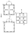
- the inlet unit 124 may consist of a flat plate having a plurality of holes 124 formed therethrough ( FIG. 2A ), or one or a plurality of main tubes 122 having a plurality of holes 124 formed therethrough ( FIG. 2B ), or one or a plurality of main tubes 122 having a plurality of holes 124 formed therethrough and a plurality of auxiliary tubes 123 communicating with the main tubes 122 and having a plurality of holes 124 ( FIGS. 2C and D ), or a plurality of tubes whose ends are distributed uniformly at the bottom of the mixing unit ( FIG. 2E ).
- the mixing unit 130 comprises a support frame 131, a main shaft rotatably coupled to the support frame 131, and 3-6 stirring blades connected to the main shaft. If necessary, a plurality of auxiliary shafts 135 may be disposed such that they are spaced apart from the main shaft 132.
- the stirring blades 133 serve to stir large amounts of anaerobic microorganisms present in the introduced water and the sludge and are coupled to the main shaft 132 such that they are spaced apart from each other at a constant interval of about 0.5-1 m, whereby the upper and lower layers in the anaerobic/oxygen-free reaction tanks are uniformly stirred to increase the area of contact between the introduced water and the anaerobic microorganisms, thereby promoting the anaerobic reaction.
- the outlet unit 140 may comprise a weir 141 for collecting the treated water, and a transfer pipe 142 for transferring the treated water into the aerobic reaction tank 200.
- this outlet unit may be provided on the inner wall of the anaerobic/oxygen-free reaction tank 100; however, it may also be provided above the mixing space of the anaerobic/oxygen-free reaction tank 100 such that it have various structures.
- FIG. 3 shows various embodiments of the outlet unit according to the present invention.
- the configuration of the weir 141 and the number and position of the transfer pipes 142 may be suitably determined by a person skilled in the art.
- a sludge collection unit (not shown) may be provided at the bottom of the anaerobic/oxygen-nee reaction tank 100.
- the sludge collection unit serves to collect excessively settled sludge and discharge the collected sludge to the outside.
- the aerobic reaction tank 200 preferably comprises an aeration tube 210 at the bottom in order to supply a sufficient amount of oxygen such that facultative microorganisms can exhibit sufficient activity.
- This aerobic reaction tank 200 may be made of any material and structure which are conventionally used in the art.
- the settling tank 300 serves to remove the sludge efficiently decomposed by facultative microorganisms in the treated water. It is preferably a gravity-type settling tank which can remove the sludge slowly by gravity to purify wastewater and obtain pure water, and may also be a settling tank having a scum-preventing plate therein. The sludge settled in the settling tank is collected and discharged by a sludge collection unit 350.
- a unit for recycling the sludge settled in the settling tank may additionally be provided.
- a portion of the sludge collected by the sludge collection unit 350 in the settling tank 300 is recycled into the reaction tank 100 through a recycle pipe 150.
- the recycled sludge may also be introduced into the water introduction unit 110 or introduced directly into the anaerobic/oxygen-free reaction tank 100, such that it is mixed with the introduced water.
- the sludge containing microorganisms is recycled to promote the reaction in the anaerobic/oxygen-free reaction tank 100. If sludge is excessively introduced or produced in the anaerobic/oxygen-free reaction tank 100, the excess portion of the sludge will be discharged to the outside using the sludge collection unit 350.
- the sewage/wastewater treatment system may be provided with one anaerobic reaction tank as shown in FIG. 1 , but may also comprise a plurality of anaerobic/oxygen-free reaction tanks which are connected directly with each other or are continuously arranged with the aerobic reaction tank interposed therebetween.
- FIG. 4 shows an embodiment in which two anaerobic/oxygen-free reaction tanks are connected directly with each other (that is, wmrobic/oxygen-free reaction tank ⁇ anaerobic/oxygen-fiee reaction tank ⁇ aerobic tank ⁇ settling tank), and FIG. 5 shows an embodiment in which two anaerobic/oxygen-free reaction tank and two aerobic reaction tanks are connected alternately with each other (that is, anaerobic/oxygen-free reaction tank ⁇ aerobic reaction tank ⁇ anaerobic/oxygen-free reaction tank ⁇ aerobic tank ⁇ settling tank).
- Such various configurations may be suitably selected depending on the overall structure and scale of the sewage/wastewater treatment system, the properties of wastewater to be treated, etc.
- the sewage/wastewater treatment system according to the present invention has an advantage in that organic wastewater containing sparingly soluble and toxic substances and nutrients (N or P) is treated using facultative microorganisms and the rectangular upflow anaerobic/oxygen-free reaction tank, whereby the treatment system of the present invention can more efficiently treat wastewater compared to the conventional sewage/wastewater system or cylindrical upflow anaerobic/oxygen-free reaction tank.
- Wastewater containing sparingly soluble and toxic water and nutrient substances (N, P) is directed into the anaerobic/oxygen-free reaction tank through the water introduction unit provided under the reaction tank and is then introduced into the anaerobic/oxygen-free reaction tank through the inlet unit connected with the water introduction unit.
- Anaerobic treatment step Fermentation in anaerobic/oxygen-free reaction tank
- activated sludge is introduced into the anaerobic/oxygen-free reaction tank. Then, the content of the mixing section in the reaction tank is continuously stirred at a speed of 3-20 rpm to induce a sufficient anaerobic reaction.
- This stirring can prevent the short circuiting of the introduced sludge/organic wastewater mixture from occurring due to an increase in the sludge concentration when the mixture in the anaerobic/oxygen-free reaction tank flows upward while it reacts. If the stirring speed in the mixing unit is less than 3 rpm, the short circuiting will appear so that no sufficient reaction will occur, and if it is more than 20 rpm, completing mixing will occur such that the advantage of the plug flow reactor cannot be used.
- Transfer step Transfer into aerobic reaction tank
- a portion of the sludge settled through the above process is collected in the sludge collection unit placed at the bottom of the anaerobic/oxygen-free reaction tank and is then discharged by a sludge discharge pump. Meanwhile, the sludge-contained treated water that flows upward is transferred from the anaerobic/oxygen-free reaction tank into the aerobic tank through the outlet unit (weir) located at the upper portion of the anaerobic/oxygen-free reaction tank.
- Aerobic treatment step Aeration in aerobic reaction tank
- Separation and discharge step Separation, discharge and sludge recycle
- the treated water which had been subjected to the aeration process is transferred into the settling tank from which pure water is separated and discharged, and the sludge settled by gravity is collected in the sludge collection unit at the bottom of the final settling tank and is discharged.
- the sludge collected in the sludge collection unit is recycled by the sludge recycle pump either into the water introduction unit provided under the anaerobic/oxygen-free reaction tank or into a recycle unit disposed within the anaerobic/oxygen-free reaction tank to promote the reaction in the anaerobic/oxygen-free reaction tank.
- An excess portion of the sludge in the anaerobic/oxygen-free reaction tank is collected in the sludge collection unit disposed in the anaerobic/oxygen-free reaction tank and is then discharged to the outside through a sludge reduction unit such as a sludge digestive unit or a dehydrating unit.
- microorganisms including Nitrosomonas, Nitrobacter, Denitrifier, Sulfate reducing bacteria, Pseudomonas, Achromobacter, Aerhorbacter, Micrococcus, Bacillus, Proteus, Flavobacterium, Acinetobacter, Corynebacterium or Mycobacterium, as well as commercially available various facultative microorganisms, may be used in the anaerobic/oxygen-free reaction tank or the aerobic reaction tank.
- the sewage/wastewater treatment system of the present invention comprising the rectangular anaerobic/oxygen-free reaction tank can economically biologically treat organic wastewater containing sparingly soluble and toxic substances, or nutrient substances, such as nitrogen or phosphorus, and heavy metals, using the existing rectangular sewage/wastewater treatment system.
Landscapes
- Life Sciences & Earth Sciences (AREA)
- Chemical & Material Sciences (AREA)
- Microbiology (AREA)
- Biodiversity & Conservation Biology (AREA)
- Engineering & Computer Science (AREA)
- Hydrology & Water Resources (AREA)
- Chemical Kinetics & Catalysis (AREA)
- Environmental & Geological Engineering (AREA)
- Water Supply & Treatment (AREA)
- Organic Chemistry (AREA)
- Health & Medical Sciences (AREA)
- Molecular Biology (AREA)
- Purification Treatments By Anaerobic Or Anaerobic And Aerobic Bacteria Or Animals (AREA)
- Mixers Of The Rotary Stirring Type (AREA)
Abstract
Description
- The present invention relates to a sewage/wastewater treatment system comprising a rectangular upflow anaerobic/oxygen-free reaction tank and a method of treating sewage/wastewater using the same. More specifically, the present invention relates to a sewage/wastewater treatment system comprising a rectangular upflow anaerobic/oxygen-free reaction tank and an economical method of treating sewage/wastewater using the same, in which organic wastewater containing sparingly soluble and toxic substances, nutrient substances (N or P) and heavy metals can be stably treated using the treatment system together with facultative microorganisms, sludge can be maintained at high concentration to reduce the sludge treatment costs, and existing equipment can be used after modification such that land costs, construction costs and operation costs can be saved.
- Generally, wastewater contains nutrient substances such as nitrogen or phosphorus, sparingly soluble and toxic substances, and heavy metals. Methods for treating such wastewater can be broadly divided into biological methods for removing wastewater containing organic matter, and physical/chemical methods for treating wastewater containing sparingly soluble and toxic substances and heavy metals.
- Typical examples of the biological wastewater treatment method include an activated sludge method employing a treatment system composed of a first settling tank, an aeration tank and a final settling tank, and a sewage/wastewater treatment method employing an aerobic/anaerobic process. However, the former method requires a means for maintaining the concentration of sludge at a specific level or higher, and the latter method does not use the activated sludge process alone, but adopts a complete mixing mode in which an aerobic reaction tank and an anaerobic/oxygen-free reaction tank which are arranged in a line are operated. Thus, in the latter method, there are problems in that it is difficult to maintain microorganisms in the reaction tanks at high concentrations and in that it is difficult to maintain a complete anaerobic state during denitrification or the induction of phosphorus discharge.
- Previously, the present inventor developed a sewage/wastewater treatment system and method for treating organic wastewater containing sparingly and toxic substance, nutrient substances such as nitrogen or phosphorus, and heavy metals, which overcome prior art problems (Korean Patent Registration No.
10-0287412 registered on January 27, 2001 - The above sewage/wastewater treatment system comprises a mixing unit combined with a cylindrical anaerobic/oxygen-free reaction tank. Thus, in the wastewater treatment system, a conventional sewage/wastewater treatment system composed of a first settling tank, a reaction tank and a final settling tank is not applied as it is, the final settling tank is modified to serve as an anaerobic/oxygen-ftee reaction tank and is operated in combination with the existing reaction tank and final settling tank.
- In the previous sewage/wastewater treatment industry, sewage/wastewater treatment systems were divided into two: one employing a cylindrical tank, and the other employing a rectangular tank. For this reason, the above improved sewage/wastewater treatment system and method were applied only to the sewage/wastewater treatment system comprising the cylindrical tank.
- Of course, the above improved method can also be applied to the sewage/wastewater treatment system having the rectangular tank. However, for this application, a cylindrical anaerobic/oxygen-free reaction tank should be newly established in place of the first rectangular settling tank such that it is operated in a combination with the existing reaction tank and final settling tank. Thus, excessive equipment investment is required.
- Accordingly, there is a need to develop an economical sewage/wastewater treatment method in which the sewage/wastewater treatment system and method (for treating organic wastewater containing sparingly soluble and toxic substances, nutrients such as nitrogen or phosphorus, and heavy metals) proposed by the present inventor can also be applied to the sewage/wastewater treatment system having the rectangular tank in an economical manner.
- Accordingly, the present invention has been made keeping in mind the above problems occurring in the prior art, and an object of the present invention is to provide a sewage/wastewater treatment system for treating organic wastewater containing sparingly soluble or toxic substances, or nutrient substances (nitrogen or phosphorus) and heavy metals, which comprises a rectangular upflow anaerobidoxygen-free reaction tank including at least one mixing unit and an improved inlet unit and outlet, in which the rectangular upflow anaerobic/oxygen-free reaction tank is combined with a conventional aerobic reaction tank and settling tank, whereby the sewage/wastewater treatment system can purify wastewater at a significantly high efficiency.
- In other words, an object of the present invention is to provide a sewage/wastewater treatment system and method in which an existing rectangular upflow sewage/wastewater system is used after modification without establishing a new system so that such that excessive equipment investment can be avoided.
- In order to accomplish the above object, the present invention provides a sewage/wastewater treatment system comprising a rectangular upflow anaerobidoxygen-free reaction tank and a method of treating sewage/wastewater using the same.
- The present invention relates to a sewage,/wastewater treatment system comprising an anaerobic/oxygen-free reaction tank, an aerobic reaction tank and a settling tank, wherein the anaerobic/oxygen-free reaction tank comprising: (1) a water introduction unit provided in the front of the anaerobic/oxygen-free reaction tank; (2) an inlet unit having a plurality of through-holes formed therein through which water introduced from the water introduction unit passes, the inlet unit communicating with the water introduction unit and being provided at the bottom of the anaerobic/oxygen-free reaction tank; (3) a mixing unit comprising a driving unit, a main shaft disposed in the anaerobic/oxygen-free reaction tank so as to be rotated by the driving means, and a plurality of spaced-apart stirring blades fixed to the main shaft at a right angle thereto; and (4) an outlet unit (weir) provided at the upper portion of the anaerobic/oxygen-free reaction tank to collect the water treated by anaerobic/oxygen-free reaction tank.
- In the present invention, in a mixing space defined between the inlet unit and outlet of the anaerobic/oxygen-free reaction tank, a plurality of spaced-apart auxiliary shafts may be disposed spaced from the main shaft such that uniform stirring and water flow are maintained throughout the mixing space.
- A sludge collection unit for collecting and discharging settled sludge may be provided at the bottom of the mixing space in the anaerobic/oxygen-free reaction tank.
- In the present invention, the inlet unit may be a plate having a plurality of through-holes formed therein, or a plurality of tubes having a plurality of holes formed therethrough, or a plurality of tubes whose ends are distributed uniformly at the bottom of the mixing space.
- The sewage/wastewater treatment system according to the preent invention may comprise one anaerobic/oxygen-free reaction tank or a plurality of anaerobic/oxygen-free reaction tanks which are connected directly with each other or disposed with the aerobic reaction tank interposed therebetween.
- In the present invention, the water introduction unit may be an introduction pipe or an introduction space. The introduction space may be a kind of retention space formed in the front of the anaerobic/oxygen-free reaction tank.
- In the present invention, a sludge collection unit for collecting and discharging settled sludge may be provided at the bottom of the aerobic reaction tank.
- Meanwhile, for optimal operation of the anaerobidoxygen-free reaction tank according to the present invention, a suitable concentration of sludge should be the reaction tank.
- Thus, in order to recycle the sludge settled in the settling tank into the anaerobic/oxygen-free reaction tank, the treatment system may preferably comprise a recycle pipe, one end of which communicates with the bottom of the settling tank, and the other end of which communicates with the introduction unit or the anaerobic/oxygen-free reaction tank.
- The present invention relates to a method of treating sewage/wastewater using the above-described sewage/wastewater treatment system, the method comprising the steps of: (A) introducing water into the anaerobic/oxygen-free reaction tank through the water introduction unit and the inlet unit (introduction step); (B) stirring the content of the mixing unit at a speed of 3-20 rpm to prevent deflection of the water flowing upward while anaerobically treating the water (anaerobic treatment step); (C) transferring the anaerobically treated, sludge-containing water from the anaerobidoxygen-free reaction tank through the outlet unit into the aerobic reaction tank (transfer step); (D) supplying a sufficient amount of oxygen to the anaerobically treated, sludge-containing water in the aerobic reaction tank to aerobically treat the water (aerobic treatment step); and (E) transferring the aerobically treated water into the settling tank, separating the transferred water into supernatant water and settled sludge by gravity, and discharging the supernatant water and the sludge separately (separation and discharge step).
- In the sewage/waste water treatment method according to the present invention, in order to maintain the concentration of sludge in the anaerobic/oxygen-free reaction tank at a specific level or higher, introduction step (A) preferably comprises recycling a portion of the sludge from the settling tank into the anaerobic/oxygen-free reaction tank through the recycle pipe.
- As used herein, the term "inlet unit" refers to a plate or tube, one side of which is connected directly to the water introduction unit, and which is disposed at the bottom of the anaerobic/oxygen-free reaction tank such that the introduced water is spread uniformly throughout the anaerobic/oxygen-free reaction tank.
- In the present invention, a specific support frame may be applied to rotatably fix the mixing unit (comprising the driving unit, the main shaft which is rotated by the driving means, etc.).
- The water introduction unit is a pipe or space for introducing water, which is provided under the anaerobic/oxygen-free reaction tank. Because water and recycled sludge are introduced into the water introduction unit, a separate mixing unit (not shown; for example, a stirring blade and a driving motor) for mixing the water and the recycled sludge uniformly is preferably provided at any position of the water introduction unit.
- The inlet unit is disposed at the bottom of the wiwrobic/oxygen-free reaction tank while one side thereof is connected with the water introduction unit. It functions to spread the water (or recycled sludge-containing water), introduced from the water introduction unit, uniformly through the horizontal surface of the anaerobic/oxygen-free reaction tank (mixing unit). Thus, the inlet unit is connected directly with the water introduction unit and may consist of a flat plate having a plurality of holes formed therethrough, or one or a plurality of main tubes having a plurality of holes formed therethrough, or one or a plurality of main tubes having a plurality of holes formed therethrough and a plurality of auxiliary tubes communicating with the main tubes and having a plurality of holes, or a plurality of tubes whose ends are distributed uniformly at the bottom of the mixing unit.
- Also, in the mixing unit, the main shaft to which the stirring blades are attached is coupled to the support frame, such that water introduced into the anaerobic/oxygen-free reaction tank is stirred by the rotation of the stirring blades, whereby an anaerobic reaction by microorganisms under anaerobic conditions actively occurs to efficiently purify organic wastewater containing sparingly and toxic substances and nutrient substances.
- In this mixing unit, the number of the main shaft and the auxiliary shafts, which are coupled to the support flame, are determined according to the size of the anaerobic/oxygen-free reaction tank, uniform stirring can occur throughout the anaerobic/oxygen-free reaction tank.
- Also, the outlet unit preferably comprises a weir and may, if necessary, further comprise a separate transfer tube. The weir functions to collect the water, which was treated in the anaerobic/oxygen-free reaction tank and flows upward, and it may be provided on the inner all of the anaerobic/oxygen-free reaction tank or be disposed so as to connect the opposite walls of the reaction tanks to each other, such that it can collect the treated water and a portion of the sludge.
- A sludge collection unit may be provided on the bottom of the anaerobic/oxygen-free reaction tank in order to remove an excess portion of the sludge contained in the anaerobic/oxygen-free reaction tank. Specifically, the bottom of the anaerobic/oxygen-free reaction tank may be inclined such that the sludge collected at the bottom of anaerobic/oxygen-free reaction tank can be discharged. Alternatively, a scraper may be disposed adjacent to the bottom of the anaerobic/oxygen-free reaction tank such that sludge can be collected and discharged by the scraper.
- Meanwhile, the sewage/wastewater treatment of the present invention may further comprise a recycle pipe for transferring sludge from the settling tank into the anaerobic/oxygen-free reaction tank. One end of the recycle pipe may be connected to the bottom of the settling tank, and the other end of the recycle pipe may be connected to the water introduction unit or to a recycle unit provided in the anaerobic/oxygen-free reaction tank.
- The recycle pipe serves to recycle sludge suitable of the living of microorganisms to the anaerobic/oxygen-free reaction tank.
- The recycle unit serves to spread the recycled sludge uniformly into the anaerobic/oxygen-free reaction tank and may have a structure in which a plurality of tubes are connected to form a lattice and a plurality of through-holes are formed at the upper portion of the tubes. The recycle unit has a structure equal or similar to the above-described inlet unit and may be provided in the anaerobic/oxygen-free reaction tank or may be the inlet unit itself.
- If the recycle unit is provided in the anaerobic/oxygen-free reaction tank, the recycle unit is connected directly to the recycle unit, and if it is not provided in the anaerobic/oxygen-free reaction tank, the recycle pipe is connected to the water introduction unit such that the recycled sludge is mixed with water in the water introduction unit and supplied to the anaerobic/oxygen-free reaction tank.
- When the sewage/wastewater treatment system comprising the rectangular upflow anaerobic/oxygen-free reaction tank according to the present invention is used, organic wastewater containing sparingly and toxic substances, or nutrient substances (such as nitrogen or phosphorus) and heavy metals, can be biologically treated. In addition, a high concentration of sludge can be maintained in the reaction tanks, so that the volume of the reaction tanks can be reduced compared to that of other biological reaction tanks, and thus the reaction tanks of the present invention can economically treat wastewater.
- Particularly, the rectangular upflow anaerobic/oxygen-free reaction tank of the present invention can maintain sludge at high concentration, and thus, when it is applied to a sewage treatment plant, a concentration tank can be omitted from the sewage treatment plant. Additionally, the present invention can be achieved using existing rectangular sewage/wastewater treatment systems, and land costs, construction costs and operation costs can be saved.
-
-
FIG. 1 is a top view of a sewage/wastewater treatment system according to one embodiment of the present invention. -
FIG. 2 is a top view showing various embodiments of an inlet unit according to the present invention. -
FIG. 3 is a top view showing various embodiments of an outlet unit according to the present invention. -
FIG. 4 is a top view showing an embodiment in which a plurality of anaerobic/oxygen-free reaction tanks are provided. -
FIG. 4 is a top view showing another embodiment in which a plurality of anaerobic/oxygen-free reaction tanks are provided. - Hereinafter, the present invention will be described in further detail with reference to the accompanying drawings. However, these drawings and the description thereof are intended to illustrate rather than limit the technical idea and scope of the present invention. It will be obvious to those skilled in the art that various modifications are possible within the scope of the technical idea of the present invention. Meanwhile, the drawings show that an anaerobic/oxygen-free reaction tank, an aerobic reaction tank and a settling tank are disposed adjacent to each other, but it will be obvious that the position, specification and configuration of these tanks may be modified in various manners.
-
FIG. 1 shows a sewage/wastewater treatment system comprising a rectangular upflow anaerobic/oxygen-free reaction tank according to the present invention. In the figure, awater introduction unit 110 consists of a space in the front of an anaerobic/oxygen-free reaction tank 100, but may, if necessary, consist of a pipe connected directly to thetank 100. - As shown therein, the sewage/wastewater treatment system comprises an anaerobic/oxygen-
free reaction tank 100, anaerobic reaction tank 200 and asettling tank 300. The anaerobic/oxygen-free reaction tank 100 comprises: awater introduction unit 110 for introducing wastewater into the anaerobic/oxygen-free reaction tank; aninlet unit 120 directed directly to thewater input unit 110 and serving to disperse the introduced water uniformly in the anaerobic/oxygen-free tank 100; amixing unit 130 for stirring the introduced water and sludge; an outlet unit 140 for transferring the treated water to the aerobic reaction tank; and a sludge connection unit (not shown) for collecting a sludge settled at the bottom of the anaerobic/oxygen-free reaction tank after reaction. - The
inlet unit 120 may have various structures allowing the introduced water to be dispersed uniformly throughout the horizontal surface of the anaerobic/oxygen-free reaction tank. For example, as shown inFIG. 2 , theinlet unit 124 may consist of a flat plate having a plurality ofholes 124 formed therethrough (FIG. 2A ), or one or a plurality ofmain tubes 122 having a plurality ofholes 124 formed therethrough (FIG. 2B ), or one or a plurality ofmain tubes 122 having a plurality ofholes 124 formed therethrough and a plurality of auxiliary tubes 123 communicating with themain tubes 122 and having a plurality of holes 124 (FIGS. 2C and D ), or a plurality of tubes whose ends are distributed uniformly at the bottom of the mixing unit (FIG. 2E ). - Also, the
mixing unit 130 comprises asupport frame 131, a main shaft rotatably coupled to thesupport frame 131, and 3-6 stirring blades connected to the main shaft. If necessary, a plurality ofauxiliary shafts 135 may be disposed such that they are spaced apart from themain shaft 132. - The stirring blades 133 serve to stir large amounts of anaerobic microorganisms present in the introduced water and the sludge and are coupled to the
main shaft 132 such that they are spaced apart from each other at a constant interval of about 0.5-1 m, whereby the upper and lower layers in the anaerobic/oxygen-free reaction tanks are uniformly stirred to increase the area of contact between the introduced water and the anaerobic microorganisms, thereby promoting the anaerobic reaction. - Also, the outlet unit 140 may comprise a
weir 141 for collecting the treated water, and atransfer pipe 142 for transferring the treated water into theaerobic reaction tank 200. As shown inFIG, 1 , this outlet unit may be provided on the inner wall of the anaerobic/oxygen-free reaction tank 100; however, it may also be provided above the mixing space of the anaerobic/oxygen-free reaction tank 100 such that it have various structures.FIG. 3 shows various embodiments of the outlet unit according to the present invention. The configuration of theweir 141 and the number and position of thetransfer pipes 142 may be suitably determined by a person skilled in the art. - A sludge collection unit (not shown) may be provided at the bottom of the anaerobic/oxygen-
nee reaction tank 100. The sludge collection unit serves to collect excessively settled sludge and discharge the collected sludge to the outside. - The
aerobic reaction tank 200 preferably comprises anaeration tube 210 at the bottom in order to supply a sufficient amount of oxygen such that facultative microorganisms can exhibit sufficient activity. Thisaerobic reaction tank 200 may be made of any material and structure which are conventionally used in the art. - Also, the
settling tank 300 serves to remove the sludge efficiently decomposed by facultative microorganisms in the treated water. It is preferably a gravity-type settling tank which can remove the sludge slowly by gravity to purify wastewater and obtain pure water, and may also be a settling tank having a scum-preventing plate therein. The sludge settled in the settling tank is collected and discharged by asludge collection unit 350. - Meanwhile, according to the present invention, a unit for recycling the sludge settled in the settling tank may additionally be provided. In other words, a portion of the sludge collected by the
sludge collection unit 350 in thesettling tank 300 is recycled into thereaction tank 100 through arecycle pipe 150. The recycled sludge may also be introduced into thewater introduction unit 110 or introduced directly into the anaerobic/oxygen-free reaction tank 100, such that it is mixed with the introduced water. - According to the above-described method, the sludge containing microorganisms is recycled to promote the reaction in the anaerobic/oxygen-
free reaction tank 100. If sludge is excessively introduced or produced in the anaerobic/oxygen-free reaction tank 100, the excess portion of the sludge will be discharged to the outside using thesludge collection unit 350. - Meanwhile, the sewage/wastewater treatment system according to the present invention may be provided with one anaerobic reaction tank as shown in
FIG. 1 , but may also comprise a plurality of anaerobic/oxygen-free reaction tanks which are connected directly with each other or are continuously arranged with the aerobic reaction tank interposed therebetween. -
FIG. 4 shows an embodiment in which two anaerobic/oxygen-free reaction tanks are connected directly with each other (that is, wmrobic/oxygen-free reaction tank → anaerobic/oxygen-fiee reaction tank → aerobic tank → settling tank), andFIG. 5 shows an embodiment in which two anaerobic/oxygen-free reaction tank and two aerobic reaction tanks are connected alternately with each other (that is, anaerobic/oxygen-free reaction tank → aerobic reaction tank → anaerobic/oxygen-free reaction tank → aerobic tank → settling tank). Such various configurations may be suitably selected depending on the overall structure and scale of the sewage/wastewater treatment system, the properties of wastewater to be treated, etc. - As described above, the sewage/wastewater treatment system according to the present invention has an advantage in that organic wastewater containing sparingly soluble and toxic substances and nutrients (N or P) is treated using facultative microorganisms and the rectangular upflow anaerobic/oxygen-free reaction tank, whereby the treatment system of the present invention can more efficiently treat wastewater compared to the conventional sewage/wastewater system or cylindrical upflow anaerobic/oxygen-free reaction tank.
- Hereinafter, each step of the method for treating sewage/wastewater using the sewage/wastewater treatment system comprising the rectangular upflow anserobic/oxygen-free reaction will be described in further detail together with the operation and effect of the treatment system.
- Wastewater containing sparingly soluble and toxic water and nutrient substances (N, P) is directed into the anaerobic/oxygen-free reaction tank through the water introduction unit provided under the reaction tank and is then introduced into the anaerobic/oxygen-free reaction tank through the inlet unit connected with the water introduction unit.
- In order to more efficiently purify the water (containing sparingly soluble and toxic water and nutrient substances (N, P)) introduced into the anaerobic/oxygen-free reaction tank as described above, activated sludge is introduced into the anaerobic/oxygen-free reaction tank. Then, the content of the mixing section in the reaction tank is continuously stirred at a speed of 3-20 rpm to induce a sufficient anaerobic reaction.
- This stirring can prevent the short circuiting of the introduced sludge/organic wastewater mixture from occurring due to an increase in the sludge concentration when the mixture in the anaerobic/oxygen-free reaction tank flows upward while it reacts. If the stirring speed in the mixing unit is less than 3 rpm, the short circuiting will appear so that no sufficient reaction will occur, and if it is more than 20 rpm, completing mixing will occur such that the advantage of the plug flow reactor cannot be used.
- A portion of the sludge settled through the above process is collected in the sludge collection unit placed at the bottom of the anaerobic/oxygen-free reaction tank and is then discharged by a sludge discharge pump. Meanwhile, the sludge-contained treated water that flows upward is transferred from the anaerobic/oxygen-free reaction tank into the aerobic tank through the outlet unit (weir) located at the upper portion of the anaerobic/oxygen-free reaction tank.
- To the sludge-containing treated water transferred from the anaerobic/oxygen-free reaction tank, a sufficient amount of oxygen is supplied through the aeration tube. Then, the activity of aerobic or facultative microorganisms in the sludge increases so that various organic substances in the wastewater are decomposed by oxidation into inorganic substances such as H2O or CO2, and ammonia nitrogen and organic nitrogen are converted into nitrate nitrogen, and the microorganisms in the sludge take an excess of phosphorus.
- In this step, in order to more efficiently purify the organic wastewater containing sparingly soluble and toxic water and nutrient substances (N, P), a portion of the treated water which had been subjected to the aeration process in the aerobic reaction tank may be recycled into the anaerobic/oxygen-free reaction tank.
- The treated water which had been subjected to the aeration process is transferred into the settling tank from which pure water is separated and discharged, and the sludge settled by gravity is collected in the sludge collection unit at the bottom of the final settling tank and is discharged.
- The sludge collected in the sludge collection unit is recycled by the sludge recycle pump either into the water introduction unit provided under the anaerobic/oxygen-free reaction tank or into a recycle unit disposed within the anaerobic/oxygen-free reaction tank to promote the reaction in the anaerobic/oxygen-free reaction tank. An excess portion of the sludge in the anaerobic/oxygen-free reaction tank is collected in the sludge collection unit disposed in the anaerobic/oxygen-free reaction tank and is then discharged to the outside through a sludge reduction unit such as a sludge digestive unit or a dehydrating unit.
- In the sewage/wastewater treatment method according to the present invention, microorganisms, including Nitrosomonas, Nitrobacter, Denitrifier, Sulfate reducing bacteria, Pseudomonas, Achromobacter, Aerhorbacter, Micrococcus, Bacillus, Proteus, Flavobacterium, Acinetobacter, Corynebacterium or Mycobacterium, as well as commercially available various facultative microorganisms, may be used in the anaerobic/oxygen-free reaction tank or the aerobic reaction tank.
- As described above, the sewage/wastewater treatment system of the present invention comprising the rectangular anaerobic/oxygen-free reaction tank can economically biologically treat organic wastewater containing sparingly soluble and toxic substances, or nutrient substances, such as nitrogen or phosphorus, and heavy metals, using the existing rectangular sewage/wastewater treatment system.
- Although the preferred embodiments of the present invention have been disclosed for illustrative purposes, those skilled in the art will appreciate that various modifications, additions and substitutions are possible, without departing from the scope and spirit of the invention as disclosed in the accompanying claims.
Claims (6)
- A sewage/wastewater treatment system comprising an anaerobic/oxygen-free reaction tank, an aerobic reaction tank and a settling tank, wherein the anaerobic/oxygen-free reaction tank comprising:a water introduction unit provided in the front of the anaerobic/oxygen-free reaction tank;an inlet unit having a plurality of through-holes formed therein through which water introduced from the water introduction unit passes, the inlet unit communicating with the water introduction unit and being provided at the bottom of the anaerobic/oxygen-free reaction tank;a mixing unit comprising a driving unit, a main shaft disposed in the anaerobic/oxygen-free reaction tank so as to be rotated by the driving means, and a plurality of spaced-apart stirring blades fixed to the main shaft at a right angle thereto; andan outlet unit (weir) provided at the upper portion of the anaerobic/oxygen-free reaction tank to collect the water treated by anaerobic/oxygen-free reaction tank.
- The sewage/wastewater treatment system of claim 1, wherein the sewage/wastewater treatment system comprises a plurality of the anaerobic/oxygen-free reaction chambers which are connected directly to each other or disposed with the aerobic reaction tank interposed therenbetween.
- The sewage/wastewater treatment system of claim 1 or 2, wherein the water inlet unit is an introduction pipe or an introduction space.
- The sewage/wastewater treatment system of claim 1 or 2, further comprising a recycle pipe for recycling sludge from the settling tank into the anaerobic/oxygen-free reaction tank, in which one end of the recycle pipe is connected to the bottom of the settling tank, and the other end of the recycle pipe is connected to the inlet unit or the anaerobic/oxygen-free reaction tank.
- A method of treating sewage/wastewater using the sewage/wastewater treatment system of claim 1 or 2, the method comprising the steps of(A) introducing water into the anaerobic/oxygen-free reaction tank through the water introduction unit and the inlet unit (introduction step);(B) stirring the content of the mixing unit at a speed of 3-20 rpm to prevent deflection of the water flowing upward while anaerobically treating the water (anaerobic treatment step);(C) transferring the anaerobically treated, sludge-containing water from the anaerobic/oxygen-free reaction tank through the outlet unit into the aerobic reaction tank (transfer step);(D) supplying a sufficient amount of oxygen to the anaerobically treated, sludge-containing water in the aerobic reaction tank to aerobically treat the water (aerobic treatment step); and(E) transferring the aerobically treated water into the settling tank, separating the transferred water into supernatant water and settled sludge by gravity, and discharging the supernatant water and the sludge separately (separation and discharge step).
- A method of treating sewage/wastewater using the sewage/wastewater treatment system of claim 7, the method comprising the steps of:(A) introducing water into the anaerobic/oxygen-free reaction tank through the water introduction unit and the inlet unit, while recycling a portion of the sludge from the settling tank into the anaerobic/oxygen-free reaction tank through the recycle pipe (introduction step);(B) stirring the content of the mixing unit at a speed of 3-20 rpm to prevent deflection of the water flowing upward while anaerobically treating the water (anaerobic treatment step);(C) transferring the anaerobically treated, sludge-containing water from the anaerobic/oxygen-free reaction tank through the outlet unit into the aerobic reaction tank (transfer step);(D) supplying a sufficient amount of oxygen to the anaerobically treated, sludge-containing water in the aerobic reaction tank to aerobically treat the water (aerobic treatment step); and(E) transferring the aerobically treated water into the settling tank, separating the transferred water into supernatant water and settled sludge by gravity, and discharging the supernatant water and the sludge separately (separation and discharge step).
Applications Claiming Priority (2)
| Application Number | Priority Date | Filing Date | Title |
|---|---|---|---|
| KR20090046361A KR101147157B1 (en) | 2009-05-27 | 2009-05-27 | An Equipment For Water Treatment Comprising A Rectangle Upstreaming Anaerobic/Anoxic Reactor, And Method Of Water Treatment Using The Same |
| PCT/KR2010/002009 WO2010137796A2 (en) | 2009-05-27 | 2010-04-01 | Sewage and wastewater treatment device comprising a rectangular upstream anaerobic/oxygen-free reaction tank, and a sewage and wastewater treatment method using the same |
Publications (3)
| Publication Number | Publication Date |
|---|---|
| EP2436655A2 true EP2436655A2 (en) | 2012-04-04 |
| EP2436655A4 EP2436655A4 (en) | 2012-10-31 |
| EP2436655B1 EP2436655B1 (en) | 2016-06-08 |
Family
ID=43223187
Family Applications (1)
| Application Number | Title | Priority Date | Filing Date |
|---|---|---|---|
| EP10780707.5A Not-in-force EP2436655B1 (en) | 2009-05-27 | 2010-04-01 | Wastewater treatment installation comprising a rectangular upstream anaerobic reaction tank and method using the same |
Country Status (7)
| Country | Link |
|---|---|
| US (1) | US8323494B2 (en) |
| EP (1) | EP2436655B1 (en) |
| JP (1) | JP5344508B2 (en) |
| KR (1) | KR101147157B1 (en) |
| CN (1) | CN102438956A (en) |
| BR (1) | BRPI1007697A2 (en) |
| WO (1) | WO2010137796A2 (en) |
Cited By (3)
| Publication number | Priority date | Publication date | Assignee | Title |
|---|---|---|---|---|
| EP2877431A4 (en) * | 2012-07-26 | 2016-03-30 | Anaergia Inc | Partially divided anaerobic treatment system |
| EP3028997A1 (en) * | 2014-12-03 | 2016-06-08 | PJR Environmental, LLC | Anaerobic suspended growth biological water treatment of contaminated water |
| US9969639B2 (en) | 2012-10-12 | 2018-05-15 | Bruce Merrill Thomson | Anaerobic suspended growth treatment of contaminated water |
Families Citing this family (13)
| Publication number | Priority date | Publication date | Assignee | Title |
|---|---|---|---|---|
| KR101160970B1 (en) * | 2012-01-27 | 2012-06-29 | 주식회사 이에스엔티 | Wastewater treatment apparatus |
| WO2014025403A1 (en) * | 2012-08-09 | 2014-02-13 | Siemens Industry, Inc. | Headshaft |
| KR101303820B1 (en) * | 2013-05-03 | 2013-09-04 | 주식회사 미래지앤씨 | Water treatmen apparatus for removing nitrogen and phosphorus using upflow and downflow complete mixing chain reaction |
| CN104928158B (en) * | 2015-06-25 | 2018-02-13 | 南安市绿野沼气技术开发研究所 | One kind precipitation fermentation integrated methane generating means |
| CN105130104B (en) * | 2015-08-12 | 2018-09-28 | 浙江大学舟山海洋研究中心 | A kind of waste water biochemical treatment device and application |
| GB2551344B (en) | 2016-06-13 | 2022-01-19 | Woxford Environmental Tech Uk Ltd | Anaerobic reactor |
| CN108689465B (en) * | 2018-07-17 | 2023-11-24 | 兴源环境科技股份有限公司 | Mixed sewage short-range treatment system and method |
| CN109250818B8 (en) * | 2018-11-14 | 2022-04-12 | 重庆大学 | Vertical baffling type denitrification filter tank for solid carbon source |
| CN109734178A (en) * | 2018-12-21 | 2019-05-10 | 佛山市玉凰生态环境科技有限公司 | Domestic sewage treatment device |
| CN112390302B (en) * | 2020-10-12 | 2023-07-07 | 安徽省建设工程测试研究院有限责任公司 | Stirring-free sewage treatment device and application method thereof |
| KR102607197B1 (en) | 2022-11-01 | 2023-11-30 | 주식회사 티엔티 | High-concentration landfill leachate, livestock wastewater, manure, food wastewater, industrial wastewater and low-concentration wastewater treatment system using an upflow complex bioreactor |
| CN118878150A (en) * | 2024-09-05 | 2024-11-01 | 中建八局广西建设有限公司 | AAO integrated sewage treatment equipment and adaptive control method |
| KR102801452B1 (en) * | 2024-09-26 | 2025-04-29 | 영남대학교 산학협력단 | Method for Wastewater Using Microorganism |
Family Cites Families (20)
| Publication number | Priority date | Publication date | Assignee | Title |
|---|---|---|---|---|
| US4253947A (en) * | 1979-02-12 | 1981-03-03 | Kansas State University Research Foundation | Method for wastewater treatment in fluidized bed biological reactors |
| JPS59150597A (en) * | 1983-02-16 | 1984-08-28 | Kurita Water Ind Ltd | Dephosphorizer |
| US4650585A (en) * | 1984-04-17 | 1987-03-17 | Air Products And Chemicals, Inc. | Method for minimizing diurnal swing in phosphorus content of effluent streams from wastewater treating plants |
| JPS61234996A (en) * | 1985-04-09 | 1986-10-20 | Toyo Patent & Eng Kk | Fermentation tank for treating filthy water using anaerobic organism |
| JP3302227B2 (en) * | 1995-09-06 | 2002-07-15 | シャープ株式会社 | Wastewater treatment device and wastewater treatment method |
| KR100287412B1 (en) * | 1998-11-11 | 2001-04-16 | 권중천 | Wastewater treatment apparatus including upflow anaerobic reactor and wastewater treatment method using the same |
| KR100397697B1 (en) * | 2001-01-19 | 2003-09-13 | 주식회사 에코다임 | An Anaerobic Bioreactor for the Wastewater-Treatment Plant |
| KR20020089085A (en) * | 2001-05-23 | 2002-11-29 | 쌍용건설 주식회사 | Apparatus for treating Nitrogen and Phosphorus in wastewater and A Treatment method thereof |
| KR100399295B1 (en) * | 2001-07-23 | 2003-09-26 | 삼성에버랜드 주식회사 | Reactor installed in baffle |
| US6911149B2 (en) * | 2001-12-19 | 2005-06-28 | Utah State University | Induced sludge bed anaerobic reactor |
| US7060185B2 (en) * | 2003-04-21 | 2006-06-13 | Korea Institute Of Construction Technology | Sewage treatment apparatus using self-granulated activated sludge and sewage treatment method thereof |
| KR100542431B1 (en) * | 2004-02-13 | 2006-01-11 | 대림산업 주식회사 | High concentration organic wastewater treatment system combining biofilm fermentation tank and anaerobic, anaerobic and aerobic tank |
| US7311833B2 (en) * | 2004-03-03 | 2007-12-25 | Kazuo Yamamoto | Zero excess sludge membrane bioreactor |
| EP1686098B1 (en) * | 2005-01-26 | 2011-02-23 | Aquatech, Ltd. | Aerobic anaerobic treatment of organically polluted water |
| JP2006255514A (en) * | 2005-03-15 | 2006-09-28 | Kobelco Eco-Solutions Co Ltd | Organic waste water treatment apparatus and organic waste water treatment method |
| CN100457652C (en) * | 2005-12-26 | 2009-02-04 | 北京城市排水集团有限责任公司 | Five-factor wastewater treating apparatus |
| KR100563449B1 (en) * | 2005-12-30 | 2006-03-22 | (주)경북환경 | Semi-batch sewage treatment apparatus and method |
| JP4936791B2 (en) * | 2006-05-22 | 2012-05-23 | 株式会社東芝 | Aeration-less water treatment system |
| US7972502B2 (en) * | 2007-07-04 | 2011-07-05 | Kabushiki Kaisha Toshiba | Aeration-less water treatment apparatus |
| KR100971880B1 (en) * | 2007-09-11 | 2010-07-22 | 주식회사 에코다임 | Horizontal Flow Sedimentation System |
-
2009
- 2009-05-27 KR KR20090046361A patent/KR101147157B1/en not_active Expired - Fee Related
-
2010
- 2010-04-01 BR BRPI1007697A patent/BRPI1007697A2/en not_active IP Right Cessation
- 2010-04-01 EP EP10780707.5A patent/EP2436655B1/en not_active Not-in-force
- 2010-04-01 JP JP2012512944A patent/JP5344508B2/en not_active Expired - Fee Related
- 2010-04-01 WO PCT/KR2010/002009 patent/WO2010137796A2/en not_active Ceased
- 2010-04-01 CN CN2010800226101A patent/CN102438956A/en active Pending
-
2011
- 2011-11-28 US US13/305,579 patent/US8323494B2/en not_active Expired - Fee Related
Cited By (3)
| Publication number | Priority date | Publication date | Assignee | Title |
|---|---|---|---|---|
| EP2877431A4 (en) * | 2012-07-26 | 2016-03-30 | Anaergia Inc | Partially divided anaerobic treatment system |
| US9969639B2 (en) | 2012-10-12 | 2018-05-15 | Bruce Merrill Thomson | Anaerobic suspended growth treatment of contaminated water |
| EP3028997A1 (en) * | 2014-12-03 | 2016-06-08 | PJR Environmental, LLC | Anaerobic suspended growth biological water treatment of contaminated water |
Also Published As
| Publication number | Publication date |
|---|---|
| CN102438956A (en) | 2012-05-02 |
| JP5344508B2 (en) | 2013-11-20 |
| WO2010137796A2 (en) | 2010-12-02 |
| JP2012528001A (en) | 2012-11-12 |
| KR20100127984A (en) | 2010-12-07 |
| EP2436655B1 (en) | 2016-06-08 |
| KR101147157B1 (en) | 2012-05-25 |
| EP2436655A4 (en) | 2012-10-31 |
| US8323494B2 (en) | 2012-12-04 |
| WO2010137796A3 (en) | 2011-03-31 |
| US20120067800A1 (en) | 2012-03-22 |
| BRPI1007697A2 (en) | 2018-02-20 |
Similar Documents
| Publication | Publication Date | Title |
|---|---|---|
| EP2436655B1 (en) | Wastewater treatment installation comprising a rectangular upstream anaerobic reaction tank and method using the same | |
| US5514277A (en) | Treatment of wastewater and sludges | |
| JP3729332B2 (en) | Wastewater treatment apparatus including upflow anaerobic reactor and wastewater treatment method using the same | |
| US9938173B2 (en) | Apparatus for water, wastewater, and waste treatment | |
| CN114291964B (en) | Sewage treatment system and method for denitrification and phosphorus recovery | |
| CN107162339A (en) | Return flow technique | |
| CN102161554A (en) | Anaerobic hydrolysis-acidification and anoxic-aerobic process-sequencing batch reactor (AO-SBR) integrated sewage treatment reaction tank | |
| JP7620327B2 (en) | Microbial Reactor | |
| CN108383320A (en) | A kind of integrated processing method of livestock breeding wastewater | |
| CN217868539U (en) | Sewage treatment device convenient to move | |
| KR100397697B1 (en) | An Anaerobic Bioreactor for the Wastewater-Treatment Plant | |
| CN108178454A (en) | A kind of non-membrane treating method of kitchen garbage, waste-water | |
| CN108191159A (en) | A kind of non-embrane method processing system of kitchen garbage, waste-water | |
| KR100373745B1 (en) | Device and method of sewage ·waste water management in sbr construction | |
| CN204058056U (en) | A kind of Continuous Flow permanent water level SBR waste disposal plant | |
| CN107129119A (en) | A kind of biochemical treatment apparatus and technique for realizing high CO_2 density | |
| CN207792993U (en) | A kind of pretreatment system of kitchen garbage, waste-water | |
| JP2024049232A (en) | Solid-liquid separation device and activated sludge treatment method | |
| CN210656594U (en) | Biological treatment device for percolate | |
| CN207792815U (en) | A kind of kitchen garbage, waste-water biochemical treatment system | |
| CN107324608A (en) | A kind of sewage water treatment method and device | |
| CN217732905U (en) | High-efficient nitrogen and phosphorus removal integration sewage treatment device | |
| KR102440990B1 (en) | Livestock wastewater treatment device and treatment method | |
| CN218931842U (en) | Sludge reduction sewage treatment system | |
| CN214653933U (en) | Sewage treatment equipment for efficient denitrification |
Legal Events
| Date | Code | Title | Description |
|---|---|---|---|
| PUAI | Public reference made under article 153(3) epc to a published international application that has entered the european phase |
Free format text: ORIGINAL CODE: 0009012 |
|
| 17P | Request for examination filed |
Effective date: 20111214 |
|
| AK | Designated contracting states |
Kind code of ref document: A2 Designated state(s): AT BE BG CH CY CZ DE DK EE ES FI FR GB GR HR HU IE IS IT LI LT LU LV MC MK MT NL NO PL PT RO SE SI SK SM TR |
|
| DAX | Request for extension of the european patent (deleted) | ||
| A4 | Supplementary search report drawn up and despatched |
Effective date: 20120927 |
|
| RIC1 | Information provided on ipc code assigned before grant |
Ipc: C02F 103/02 20060101ALI20120921BHEP Ipc: C02F 3/30 20060101AFI20120921BHEP Ipc: C02F 3/28 20060101ALI20120921BHEP |
|
| 17Q | First examination report despatched |
Effective date: 20150212 |
|
| GRAP | Despatch of communication of intention to grant a patent |
Free format text: ORIGINAL CODE: EPIDOSNIGR1 |
|
| RIC1 | Information provided on ipc code assigned before grant |
Ipc: C02F 101/30 20060101ALN20151118BHEP Ipc: B01F 13/10 20060101ALI20151118BHEP Ipc: C02F 3/30 20060101AFI20151118BHEP Ipc: B01F 3/04 20060101ALI20151118BHEP Ipc: B01F 7/32 20060101ALI20151118BHEP Ipc: C02F 3/28 20060101ALI20151118BHEP Ipc: C02F 101/20 20060101ALN20151118BHEP Ipc: B01F 7/16 20060101ALI20151118BHEP |
|
| RIC1 | Information provided on ipc code assigned before grant |
Ipc: C02F 101/20 20060101ALN20151126BHEP Ipc: C02F 3/30 20060101AFI20151126BHEP Ipc: B01F 7/16 20060101ALI20151126BHEP Ipc: C02F 101/30 20060101ALN20151126BHEP Ipc: B01F 3/04 20060101ALI20151126BHEP Ipc: B01F 7/32 20060101ALI20151126BHEP Ipc: B01F 13/10 20060101ALI20151126BHEP Ipc: C02F 3/28 20060101ALI20151126BHEP |
|
| RIC1 | Information provided on ipc code assigned before grant |
Ipc: B01F 7/32 20060101ALI20151201BHEP Ipc: C02F 3/28 20060101ALI20151201BHEP Ipc: B01F 13/10 20060101ALI20151201BHEP Ipc: C02F 3/30 20060101AFI20151201BHEP Ipc: C02F 101/20 20060101ALN20151201BHEP Ipc: C02F 101/30 20060101ALN20151201BHEP Ipc: B01F 3/04 20060101ALI20151201BHEP Ipc: B01F 7/16 20060101ALI20151201BHEP |
|
| INTG | Intention to grant announced |
Effective date: 20151216 |
|
| GRAS | Grant fee paid |
Free format text: ORIGINAL CODE: EPIDOSNIGR3 |
|
| GRAA | (expected) grant |
Free format text: ORIGINAL CODE: 0009210 |
|
| AK | Designated contracting states |
Kind code of ref document: B1 Designated state(s): AT BE BG CH CY CZ DE DK EE ES FI FR GB GR HR HU IE IS IT LI LT LU LV MC MK MT NL NO PL PT RO SE SI SK SM TR |
|
| REG | Reference to a national code |
Ref country code: GB Ref legal event code: FG4D |
|
| REG | Reference to a national code |
Ref country code: CH Ref legal event code: EP |
|
| REG | Reference to a national code |
Ref country code: IE Ref legal event code: FG4D |
|
| REG | Reference to a national code |
Ref country code: AT Ref legal event code: REF Ref document number: 805101 Country of ref document: AT Kind code of ref document: T Effective date: 20160715 |
|
| REG | Reference to a national code |
Ref country code: DE Ref legal event code: R096 Ref document number: 602010033972 Country of ref document: DE |
|
| REG | Reference to a national code |
Ref country code: NL Ref legal event code: MP Effective date: 20160608 |
|
| REG | Reference to a national code |
Ref country code: LT Ref legal event code: MG4D |
|
| PG25 | Lapsed in a contracting state [announced via postgrant information from national office to epo] |
Ref country code: NL Free format text: LAPSE BECAUSE OF FAILURE TO SUBMIT A TRANSLATION OF THE DESCRIPTION OR TO PAY THE FEE WITHIN THE PRESCRIBED TIME-LIMIT Effective date: 20160608 Ref country code: NO Free format text: LAPSE BECAUSE OF FAILURE TO SUBMIT A TRANSLATION OF THE DESCRIPTION OR TO PAY THE FEE WITHIN THE PRESCRIBED TIME-LIMIT Effective date: 20160908 Ref country code: LT Free format text: LAPSE BECAUSE OF FAILURE TO SUBMIT A TRANSLATION OF THE DESCRIPTION OR TO PAY THE FEE WITHIN THE PRESCRIBED TIME-LIMIT Effective date: 20160608 Ref country code: FI Free format text: LAPSE BECAUSE OF FAILURE TO SUBMIT A TRANSLATION OF THE DESCRIPTION OR TO PAY THE FEE WITHIN THE PRESCRIBED TIME-LIMIT Effective date: 20160608 |
|
| REG | Reference to a national code |
Ref country code: AT Ref legal event code: MK05 Ref document number: 805101 Country of ref document: AT Kind code of ref document: T Effective date: 20160608 |
|
| PG25 | Lapsed in a contracting state [announced via postgrant information from national office to epo] |
Ref country code: GR Free format text: LAPSE BECAUSE OF FAILURE TO SUBMIT A TRANSLATION OF THE DESCRIPTION OR TO PAY THE FEE WITHIN THE PRESCRIBED TIME-LIMIT Effective date: 20160909 Ref country code: LV Free format text: LAPSE BECAUSE OF FAILURE TO SUBMIT A TRANSLATION OF THE DESCRIPTION OR TO PAY THE FEE WITHIN THE PRESCRIBED TIME-LIMIT Effective date: 20160608 Ref country code: SE Free format text: LAPSE BECAUSE OF FAILURE TO SUBMIT A TRANSLATION OF THE DESCRIPTION OR TO PAY THE FEE WITHIN THE PRESCRIBED TIME-LIMIT Effective date: 20160608 Ref country code: ES Free format text: LAPSE BECAUSE OF FAILURE TO SUBMIT A TRANSLATION OF THE DESCRIPTION OR TO PAY THE FEE WITHIN THE PRESCRIBED TIME-LIMIT Effective date: 20160608 |
|
| PG25 | Lapsed in a contracting state [announced via postgrant information from national office to epo] |
Ref country code: IS Free format text: LAPSE BECAUSE OF FAILURE TO SUBMIT A TRANSLATION OF THE DESCRIPTION OR TO PAY THE FEE WITHIN THE PRESCRIBED TIME-LIMIT Effective date: 20161008 Ref country code: EE Free format text: LAPSE BECAUSE OF FAILURE TO SUBMIT A TRANSLATION OF THE DESCRIPTION OR TO PAY THE FEE WITHIN THE PRESCRIBED TIME-LIMIT Effective date: 20160608 Ref country code: IT Free format text: LAPSE BECAUSE OF FAILURE TO SUBMIT A TRANSLATION OF THE DESCRIPTION OR TO PAY THE FEE WITHIN THE PRESCRIBED TIME-LIMIT Effective date: 20160608 Ref country code: RO Free format text: LAPSE BECAUSE OF FAILURE TO SUBMIT A TRANSLATION OF THE DESCRIPTION OR TO PAY THE FEE WITHIN THE PRESCRIBED TIME-LIMIT Effective date: 20160608 Ref country code: SK Free format text: LAPSE BECAUSE OF FAILURE TO SUBMIT A TRANSLATION OF THE DESCRIPTION OR TO PAY THE FEE WITHIN THE PRESCRIBED TIME-LIMIT Effective date: 20160608 Ref country code: CZ Free format text: LAPSE BECAUSE OF FAILURE TO SUBMIT A TRANSLATION OF THE DESCRIPTION OR TO PAY THE FEE WITHIN THE PRESCRIBED TIME-LIMIT Effective date: 20160608 |
|
| PG25 | Lapsed in a contracting state [announced via postgrant information from national office to epo] |
Ref country code: SM Free format text: LAPSE BECAUSE OF FAILURE TO SUBMIT A TRANSLATION OF THE DESCRIPTION OR TO PAY THE FEE WITHIN THE PRESCRIBED TIME-LIMIT Effective date: 20160608 Ref country code: PL Free format text: LAPSE BECAUSE OF FAILURE TO SUBMIT A TRANSLATION OF THE DESCRIPTION OR TO PAY THE FEE WITHIN THE PRESCRIBED TIME-LIMIT Effective date: 20160608 Ref country code: PT Free format text: LAPSE BECAUSE OF FAILURE TO SUBMIT A TRANSLATION OF THE DESCRIPTION OR TO PAY THE FEE WITHIN THE PRESCRIBED TIME-LIMIT Effective date: 20161010 Ref country code: AT Free format text: LAPSE BECAUSE OF FAILURE TO SUBMIT A TRANSLATION OF THE DESCRIPTION OR TO PAY THE FEE WITHIN THE PRESCRIBED TIME-LIMIT Effective date: 20160608 Ref country code: BE Free format text: LAPSE BECAUSE OF FAILURE TO SUBMIT A TRANSLATION OF THE DESCRIPTION OR TO PAY THE FEE WITHIN THE PRESCRIBED TIME-LIMIT Effective date: 20160608 |
|
| REG | Reference to a national code |
Ref country code: DE Ref legal event code: R097 Ref document number: 602010033972 Country of ref document: DE |
|
| PLBE | No opposition filed within time limit |
Free format text: ORIGINAL CODE: 0009261 |
|
| STAA | Information on the status of an ep patent application or granted ep patent |
Free format text: STATUS: NO OPPOSITION FILED WITHIN TIME LIMIT |
|
| 26N | No opposition filed |
Effective date: 20170309 |
|
| PG25 | Lapsed in a contracting state [announced via postgrant information from national office to epo] |
Ref country code: DK Free format text: LAPSE BECAUSE OF FAILURE TO SUBMIT A TRANSLATION OF THE DESCRIPTION OR TO PAY THE FEE WITHIN THE PRESCRIBED TIME-LIMIT Effective date: 20160608 Ref country code: SI Free format text: LAPSE BECAUSE OF FAILURE TO SUBMIT A TRANSLATION OF THE DESCRIPTION OR TO PAY THE FEE WITHIN THE PRESCRIBED TIME-LIMIT Effective date: 20160608 |
|
| REG | Reference to a national code |
Ref country code: DE Ref legal event code: R119 Ref document number: 602010033972 Country of ref document: DE |
|
| REG | Reference to a national code |
Ref country code: CH Ref legal event code: PL |
|
| GBPC | Gb: european patent ceased through non-payment of renewal fee |
Effective date: 20170401 |
|
| REG | Reference to a national code |
Ref country code: IE Ref legal event code: MM4A |
|
| REG | Reference to a national code |
Ref country code: FR Ref legal event code: ST Effective date: 20171229 |
|
| PG25 | Lapsed in a contracting state [announced via postgrant information from national office to epo] |
Ref country code: DE Free format text: LAPSE BECAUSE OF NON-PAYMENT OF DUE FEES Effective date: 20171103 Ref country code: FR Free format text: LAPSE BECAUSE OF NON-PAYMENT OF DUE FEES Effective date: 20170502 Ref country code: MC Free format text: LAPSE BECAUSE OF FAILURE TO SUBMIT A TRANSLATION OF THE DESCRIPTION OR TO PAY THE FEE WITHIN THE PRESCRIBED TIME-LIMIT Effective date: 20160608 |
|
| PG25 | Lapsed in a contracting state [announced via postgrant information from national office to epo] |
Ref country code: LU Free format text: LAPSE BECAUSE OF NON-PAYMENT OF DUE FEES Effective date: 20170401 Ref country code: GB Free format text: LAPSE BECAUSE OF NON-PAYMENT OF DUE FEES Effective date: 20170401 Ref country code: LI Free format text: LAPSE BECAUSE OF NON-PAYMENT OF DUE FEES Effective date: 20170430 Ref country code: CH Free format text: LAPSE BECAUSE OF NON-PAYMENT OF DUE FEES Effective date: 20170430 |
|
| PG25 | Lapsed in a contracting state [announced via postgrant information from national office to epo] |
Ref country code: IE Free format text: LAPSE BECAUSE OF NON-PAYMENT OF DUE FEES Effective date: 20170401 |
|
| PG25 | Lapsed in a contracting state [announced via postgrant information from national office to epo] |
Ref country code: MT Free format text: LAPSE BECAUSE OF NON-PAYMENT OF DUE FEES Effective date: 20170401 |
|
| PG25 | Lapsed in a contracting state [announced via postgrant information from national office to epo] |
Ref country code: HU Free format text: LAPSE BECAUSE OF FAILURE TO SUBMIT A TRANSLATION OF THE DESCRIPTION OR TO PAY THE FEE WITHIN THE PRESCRIBED TIME-LIMIT; INVALID AB INITIO Effective date: 20100401 |
|
| PG25 | Lapsed in a contracting state [announced via postgrant information from national office to epo] |
Ref country code: BG Free format text: LAPSE BECAUSE OF FAILURE TO SUBMIT A TRANSLATION OF THE DESCRIPTION OR TO PAY THE FEE WITHIN THE PRESCRIBED TIME-LIMIT Effective date: 20160608 |
|
| PG25 | Lapsed in a contracting state [announced via postgrant information from national office to epo] |
Ref country code: CY Free format text: LAPSE BECAUSE OF NON-PAYMENT OF DUE FEES Effective date: 20160608 |
|
| PG25 | Lapsed in a contracting state [announced via postgrant information from national office to epo] |
Ref country code: MK Free format text: LAPSE BECAUSE OF FAILURE TO SUBMIT A TRANSLATION OF THE DESCRIPTION OR TO PAY THE FEE WITHIN THE PRESCRIBED TIME-LIMIT Effective date: 20160608 |
|
| PG25 | Lapsed in a contracting state [announced via postgrant information from national office to epo] |
Ref country code: TR Free format text: LAPSE BECAUSE OF FAILURE TO SUBMIT A TRANSLATION OF THE DESCRIPTION OR TO PAY THE FEE WITHIN THE PRESCRIBED TIME-LIMIT Effective date: 20160608 |
|
| PG25 | Lapsed in a contracting state [announced via postgrant information from national office to epo] |
Ref country code: HR Free format text: LAPSE BECAUSE OF FAILURE TO SUBMIT A TRANSLATION OF THE DESCRIPTION OR TO PAY THE FEE WITHIN THE PRESCRIBED TIME-LIMIT Effective date: 20160608 |