EP2436567A2 - Fixing base for a windshield wiper - Google Patents
Fixing base for a windshield wiper Download PDFInfo
- Publication number
- EP2436567A2 EP2436567A2 EP11155778A EP11155778A EP2436567A2 EP 2436567 A2 EP2436567 A2 EP 2436567A2 EP 11155778 A EP11155778 A EP 11155778A EP 11155778 A EP11155778 A EP 11155778A EP 2436567 A2 EP2436567 A2 EP 2436567A2
- Authority
- EP
- European Patent Office
- Prior art keywords
- fixing base
- notch
- piece
- chamfer
- windshield wiper
- Prior art date
- Legal status (The legal status is an assumption and is not a legal conclusion. Google has not performed a legal analysis and makes no representation as to the accuracy of the status listed.)
- Withdrawn
Links
Images


Classifications
-
- B—PERFORMING OPERATIONS; TRANSPORTING
- B60—VEHICLES IN GENERAL
- B60S—SERVICING, CLEANING, REPAIRING, SUPPORTING, LIFTING, OR MANOEUVRING OF VEHICLES, NOT OTHERWISE PROVIDED FOR
- B60S1/00—Cleaning of vehicles
- B60S1/02—Cleaning windscreens, windows or optical devices
- B60S1/04—Wipers or the like, e.g. scrapers
- B60S1/32—Wipers or the like, e.g. scrapers characterised by constructional features of wiper blade arms or blades
- B60S1/38—Wiper blades
- B60S1/3848—Flat-type wiper blade, i.e. without harness
- B60S1/3849—Connectors therefor; Connection to wiper arm; Attached to blade
- B60S1/387—Connectors therefor; Connection to wiper arm; Attached to blade the connector being suitable for receiving different types of adapter
-
- B—PERFORMING OPERATIONS; TRANSPORTING
- B60—VEHICLES IN GENERAL
- B60S—SERVICING, CLEANING, REPAIRING, SUPPORTING, LIFTING, OR MANOEUVRING OF VEHICLES, NOT OTHERWISE PROVIDED FOR
- B60S1/00—Cleaning of vehicles
- B60S1/02—Cleaning windscreens, windows or optical devices
- B60S1/04—Wipers or the like, e.g. scrapers
- B60S1/32—Wipers or the like, e.g. scrapers characterised by constructional features of wiper blade arms or blades
- B60S1/38—Wiper blades
- B60S1/3848—Flat-type wiper blade, i.e. without harness
- B60S1/3849—Connectors therefor; Connection to wiper arm; Attached to blade
- B60S1/3865—Connectors having an integral pivot pin for connection with the wiper arm
- B60S1/3867—Connectors having an integral pivot pin for connection with the wiper arm pin formed on the interior of side walls
-
- B—PERFORMING OPERATIONS; TRANSPORTING
- B60—VEHICLES IN GENERAL
- B60S—SERVICING, CLEANING, REPAIRING, SUPPORTING, LIFTING, OR MANOEUVRING OF VEHICLES, NOT OTHERWISE PROVIDED FOR
- B60S1/00—Cleaning of vehicles
- B60S1/02—Cleaning windscreens, windows or optical devices
- B60S1/04—Wipers or the like, e.g. scrapers
- B60S1/32—Wipers or the like, e.g. scrapers characterised by constructional features of wiper blade arms or blades
- B60S1/40—Connections between blades and arms
- B60S1/4006—Connections between blades and arms for arms provided with a hook-shaped end
- B60S1/4009—Connections between blades and arms for arms provided with a hook-shaped end comprising a detachable intermediate element mounted on the hook-shaped end
- B60S2001/4012—Connections between blades and arms for arms provided with a hook-shaped end comprising a detachable intermediate element mounted on the hook-shaped end the element being provided with bearing surfaces on its side walls
-
- B—PERFORMING OPERATIONS; TRANSPORTING
- B60—VEHICLES IN GENERAL
- B60S—SERVICING, CLEANING, REPAIRING, SUPPORTING, LIFTING, OR MANOEUVRING OF VEHICLES, NOT OTHERWISE PROVIDED FOR
- B60S1/00—Cleaning of vehicles
- B60S1/02—Cleaning windscreens, windows or optical devices
- B60S1/04—Wipers or the like, e.g. scrapers
- B60S1/32—Wipers or the like, e.g. scrapers characterised by constructional features of wiper blade arms or blades
- B60S1/40—Connections between blades and arms
- B60S1/4038—Connections between blades and arms for arms provided with a channel-shaped end
- B60S1/4045—Connections between blades and arms for arms provided with a channel-shaped end comprising a detachable intermediate element mounted on the channel-shaped end
- B60S1/4048—Connections between blades and arms for arms provided with a channel-shaped end comprising a detachable intermediate element mounted on the channel-shaped end the element being provided with retention means co-operating with the channel-shaped end of the arm
- B60S2001/4051—Connections between blades and arms for arms provided with a channel-shaped end comprising a detachable intermediate element mounted on the channel-shaped end the element being provided with retention means co-operating with the channel-shaped end of the arm the intermediate element engaging the side walls of the arm
-
- B—PERFORMING OPERATIONS; TRANSPORTING
- B60—VEHICLES IN GENERAL
- B60S—SERVICING, CLEANING, REPAIRING, SUPPORTING, LIFTING, OR MANOEUVRING OF VEHICLES, NOT OTHERWISE PROVIDED FOR
- B60S1/00—Cleaning of vehicles
- B60S1/02—Cleaning windscreens, windows or optical devices
- B60S1/04—Wipers or the like, e.g. scrapers
- B60S1/32—Wipers or the like, e.g. scrapers characterised by constructional features of wiper blade arms or blades
- B60S1/40—Connections between blades and arms
- B60S1/4038—Connections between blades and arms for arms provided with a channel-shaped end
- B60S1/4045—Connections between blades and arms for arms provided with a channel-shaped end comprising a detachable intermediate element mounted on the channel-shaped end
- B60S1/4048—Connections between blades and arms for arms provided with a channel-shaped end comprising a detachable intermediate element mounted on the channel-shaped end the element being provided with retention means co-operating with the channel-shaped end of the arm
- B60S2001/4054—Connections between blades and arms for arms provided with a channel-shaped end comprising a detachable intermediate element mounted on the channel-shaped end the element being provided with retention means co-operating with the channel-shaped end of the arm the intermediate element engaging the back part of the arm
Landscapes
- Engineering & Computer Science (AREA)
- Mechanical Engineering (AREA)
- Cleaning Implements For Floors, Carpets, Furniture, Walls, And The Like (AREA)
- Connection Of Plates (AREA)
Abstract
Description
- The present invention relates to a fixing base for a windshield wiper, and in particular to a fixing base for a windshield wiper, which allows various kinds of connecting pieces to be assembled therewith.
- Automobile has become a popular public transportation because it can keep out wind and rain as compared to bicycles and motorcycles. Front and rear windshields of the automobile are provided with a wiper respectively for wiping off rain and dirt attached thereon, thereby protecting a person who is driving the automobile.
- The conventional windshield wiper includes a connecting piece, a fixing base and a wiper blade. The wiping blade is fixed to the bottom surface of the fixing base and attached to the windshield. The connecting piece is mounted to the top surface of the fixing base. The connecting piece is mounted to a wiper arm of the automobile, so that the wiper arm can drive the windshield wiper to swing on the windshield to thus wipe off the rain or dirt attached thereon.
- There are many kinds of automobiles, each having a dedicated wiper arm on its windshield. Of course, each kind of wiper ann can be only assembled with its dedicated connecting piece. As a result, the fixing base and the wiper blade of the windshield wiper have to be designed exclusively to fit the respective kinds of automobiles. Thus, a user has to buy a specific windshield wiper to fit his/her automobile. On the other hand, it is necessary for the manufacturer to produce various kinds of windshield wipers including their accessories such as the connecting piece, the fixing base and the wiper blade. Thus, the molds and apparatuses for manufacturing various kinds of windshield wipers are inevitably increased.
- Taking the practical operation and repair of the windshield wiper into consideration, among the accessories of the windshield wiper, the wiper blade suffers damage most frequently because it is made of a flexible material (such as plastic or rubber) and may be worn easily after a long period of time. Since the wiper blade is flexible, the wiper blade may be applicable to several kinds of automobiles within its range of elastic deformation. Thus, the fixing base of the windshield wiper on which the wiper blade is fixed becomes the most important component to determine whether the windshield wiper can be used in other kinds of automobiles.
- However, the conventional fixing base for a windshield wiper has a complicated structure. For example, Taiwan Patent No.
M506365 305183 - Therefore, it is an important issue for the present Inventor to solve the above-mentioned problems.
- The present invention is to provide a fixing base for a windshield wiper, which allows various kinds of connecting pieces to be assembled therewith and has a simple structure for easy production.
- The present invention is to provide a fixing base for a windshield wiper, the windshield wiper comprising a connecting piece and a wiper blade, the fixing base including:
- a bottom plate abutting a top surface of the wiper blade, both longitudinal sides of the bottom plate being bent to form two hooks respectively, the hooks being engaged with two lateral edges of the wiper blade; and
- two wings extending from two longitudinal sides of the bottom plate and separated from each other, a shaft rod being provided between the two wings for allowing the connecting piece to be pivotally connected thereto, each of the wings being formed with a first chamfer piece and a second chamfer piece, a first notch being provided between the first chamfer piece and the shaft rod, a second notch being provided between the second chamfer piece and the shaft rod, the shaft rod being provided between the first notch and the second notch;
- In comparison with prior art, the present invention has the following advantageous features.
- Since the fixing base is constituted of the bottom plate and two wings extending upwardly from both sides of the bottom plate, the fixing base is one-piece and is not constituted of plural components. Thus, the fixing base of the present invention has a simple structure for easy production.
- The length, width and pitch of the bottom plate and the two wings are made based on the dimensions of the existing kinds of connecting pieces. The first chamfer piece and the second chamfer piece are configured to gradually narrow towards two longitudinal ends of the fixing base. Further, the first notch and the second notch provide a space adjacent to the shaft rod for allowing various kinds of the connecting pieces to be assembled with the fixing base. The connecting piece can swing around the shaft rod and along the first chamfer piece and the second chamfer piece in the longitudinal direction of the fixing base without any mounting interference.
- Since the fixing base of the present invention allows different kinds of connecting pieces of the windshield wiper to be assembled therewith and has a simple structure for easy production, the manufacturer in this field only needs to manufacture one kind of fixing base which is applicable to various kinds of automobiles, the cost of molds and apparatuses for manufacturing the windshield wiper is decreased, and the manufacturing procedure is simplified. Further, the repairer and seller in this field need not to store various kinds of fixing bases. The repair of the windshield wiper becomes more convenient and cheaper.
-
-
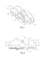
FIG 1 is a perspective view showing the external appearance of the fixing base of the present invention; -
FIG 2 is a side cross-sectional view showing the fixing base of the present invention; -
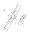
FIG 3 is an exploded perspective view showing the fixing base of the present invention as well as a connecting piece and a wiper blade of a windshield wiper; -
FIG. 4 is an assembled perspective view showing the fixing base of the present invention as well as the connecting piece and the wiper blade of the windshield wiper; -
FIG 5 is an assembled cross-sectional view showing the fixing base of the present invention as well as the connecting piece and the wiper blade of the windshield wiper; -
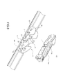
FIG 6 is an exploded perspective view showing the fixing base of the present invention and a second kind of connecting piece; -
FIG. 7 is an exploded perspective view showing the fixing base of the present invention and a third kind of connecting piece; and -
FIG. 8 is an exploded perspective view showing the fixing base of the present invention and a fourth kind of connecting piece. - The detailed description and technical contents of the present invention will become apparent with the following detailed description accompanied with related drawings. It is noteworthy to point out that the drawings is provided for the illustration purpose only, but not intended for limiting the scope of the present invention.
- Please refer to
FIGS. 1 to 5 . The present invention relates to afixing base 1 for a windshield wiper. As shown inFIG. 3 , thewindshield wiper 100 comprises a connectingpiece 110 and awiper blade 120. The connectingpiece 110 is assembled with thefixing base 1, and thefixing base 1 is fixed to the top surface of thewiper blade 120, thereby forming thewindshield wiper 1 shown inFIG 4 . - Please refer to
FIG 1 . Thefixing base 1 is made by a metallic material to form one unit. Thefixing base 1 is constituted of abottom plate 10 and twowings 20. Both longitudinal sides of thebottom plate 10 are bent to form twohooks 11 respectively. Thehooks 11 are engaged with two side edges of thewiper blade 120 respectively. - The two
wings 20 extend upwards from both longitudinal sides of thebottom plate 10 and are separated from each other. Ashaft rod 21 is provided between the twoside wings 20 for allowing the connectingpiece 110 to be pivotally connected thereto. More specifically, as shown inFIG. 4 , a middle portion of the connectingpiece 110 is provided with anotch 111 for allowing theshaft rod 21 to be pivotally inserted therein. - Each of the
wings 20 is formed with afirst chamfer piece 22 and asecond chamfer piece 23. Afirst notch 24 is provided between thefirst chamfer 23 and theshaft rod 21. Asecond notch 25 is provided between thesecond chamfer piece 23 and theshaft rod 21. Theshaft rod 21 is provided between thefirst notch 24 and thesecond notch 25. - As shown in
FIG. 2 , thefirst chamfer piece 22 and thesecond chamfer piece 23 are configured to gradually narrow toward both longitudinal ends of the fixingbase 1. Thefirst notch 24 and thesecond notch 25 provide a space adjacent to theshaft rod 21 to avoid mounting interference, thereby allowing various kinds of connectingpieces 110 to be assembled with the fixingbase 1. It should be noted that, in the embodiment shown inFIG 1 , the area of thefirst notch 24 is smaller than that of thesecond notch 25. As a result, the area of thefirst chamfer piece 22 is larger than that of thesecond chamfer piece 23. - Further, the
first chamfer piece 22 and thesecond chamfer piece 23 are provided with ahole FIG 1 , each of theholes hole 221 of thefirst chamfer piece 22 and thehole 231 of thesecond chamfer piece 23 are located in the same height with respect to thebottom plate 10. - Please refer to
FIG. 5 . It should be noted that, based on the experience and expert knowledge of the present Inventor in this field, thefirst chamfer piece 22 and thesecond chamfer piece 23 are configured to gradually narrow toward both longitudinal ends of the fixingbase 1, so that the connectingpiece 110 can swing around theshaft rod 21 and along thefirst chamfer piece 22 and thesecond chamfer piece 23 in the longitudinal direction of the fixingbase 1. In this way, the range of swinging angle of thewindshield wiper 100 is increased to fit various kinds of windshields (not shown). Further, thehole 221 of thefirst chamfer piece 22 and thehole 231 of thesecond chamfer piece 23 are designed to fit some specific connecting pieces (not shown). One end of such a specific connecting piece is provided with a hook or through-hole (not shown). The hook is engaged within thehole 221 of thefirst chamfer piece 22 or thehole 231 of thesecond chamfer piece 23. Alternatively, a pin (not shown) is disposed through thehole base 1. - Please refer to
FIGS. 6 to 8 , which show the assembly of the fixingbase 1 of the present invention with other three kinds of connectingpieces FIG 6 , a middle section of the connectingpiece 110a is provided with anotch 111a. A user puts the connectingpiece 110a under the fixingbase 1 and presses the connectingpiece 110a to thereby force theshaft rod 21 into thenotch 111a. In this way, the connectingpiece 110a is pivotally connected to theshaft rod 21. As shown inFIG. 7 , a middle section of the connectingpiece 110b is provided with anotch 111b. The user puts the connectingpiece 110b under the fixingbase 1 and presses the connectingpiece 110b to thereby force theshaft rod 21 into thenotch 111b. In this way, the connectingpiece 110b is pivotally connected to theshaft rod 21. As shown inFIG. 8 , a middle section of the connectingpiece 110c is provided with anotch 111c. The user puts the connectingpiece 110c under the fixingbase 1 and presses the connectingpiece 110c to thereby force theshaft rod 21 into thenotch 111c. In this way, the connectingpiece 110c is pivotally connected to theshaft rod 21. - As shown in
FIGS. 6 to 8 , the length, width and pitch of thebottom plate 10 and the twowings 20 are designed based on the dimensions of the current connecting pieces. Thefirst chamfer 22 and thesecond chamfer piece 23 are configured to gradually narrow towards longitudinal ends of the fixingbase 1. Thefirst notch 24 and thesecond notch 25 provide a space adjacent to theshaft rod 21 to avoid mounting interference, so that various kinds of connectingpieces base 1. Each of these different kinds of connectingpieces shaft rod 21 and along thefirst chamfer piece 22 and thesecond chamfer piece 23 in the longitudinal direction of the fixingbase 1 without any interference.
Claims (6)
- A fixing base (1) for a windshield wiper (100), the windshield wiper (100) comprising a connecting piece (110) and a wiper blade (120), the fixing base (1) including:a bottom plate (10) abutting a top surface of the wiper blade (120), both longitudinal sides of the bottom plate (10) being bent to form two hooks (11) respectively, the hooks (11) being engaged with two lateral edges of the wiper blade (120); andtwo wings (20) extending upwardly from two longitudinal sides of the bottom plate (10) and separated from each other, a shaft rod (21) being provided between the two wings (20) for allowing the connecting piece (110) to be pivotally connected thereto, each of the wings (20) being formed with a first chamfer piece (22) and a second chamfer piece (23), a first notch (24) being provided between the first chamfer piece (22) and the shaft rod (21), a second notch (25) being provided between the second chamfer piece (25) and the shaft rod (21), the shaft rod (21) being provided between the first notch (24) and the second notch (25);wherein the first chamfer piece (22) and the second chamfer piece (23) are configured to gradually narrow toward both longitudinal ends of the fixing base (1), the first notch (24) and the second notch (25) provide a space adjacent to the shaft rod (21) for allowing various kinds of the connecting pieces (110) to be assembled with the fixing base (1).
- The fixing base (1) for a windshield wiper (100) according to claim 1, wherein the fixing base (1) is made of a metallic material into one unit.
- The fixing base (1) for a windshield wiper (100) according to claim 2, wherein the area of the first notch (24) is smaller than that of the second notch (25), and the area of the first chamfer piece (22) is larger that that of the second chamfer piece (23).
- The fixing base (1) for a windshield wiper (100) according to claim 3, wherein the first chamfer piece (22) and the second chamfer piece (23) are provided with a hole (221, 231) respectively, each of the holes (221, 231) is formed into a square hole.
- The fixing base (1) for a windshield wiper (100) according to claim 4, wherein the hole (221) of the first chamfer piece (22) and the hole (231) of the second chamfer piece (23) are located in the same height with respect to the bottom plate (10).
- The fixing base (1) for a windshield wiper (100) according to claim 5, wherein the connecting piece (110) is provided with a notch (111) for allowing the shaft rod (21) to be pivotally inserted therein, the connecting piece (110) swings around the rod shaft (21) and along the first chamfer piece (22) and the second chamfer piece (23) in the longitudinal direction of the fixing base (1).
Applications Claiming Priority (1)
| Application Number | Priority Date | Filing Date | Title |
|---|---|---|---|
| TW099218855U TWM397336U (en) | 2010-09-30 | 2010-09-30 | Wiper holder |
Publications (2)
| Publication Number | Publication Date |
|---|---|
| EP2436567A2 true EP2436567A2 (en) | 2012-04-04 |
| EP2436567A3 EP2436567A3 (en) | 2013-06-19 |
Family
ID=44804339
Family Applications (1)
| Application Number | Title | Priority Date | Filing Date |
|---|---|---|---|
| EP11155778.1A Withdrawn EP2436567A3 (en) | 2010-09-30 | 2011-02-24 | Fixing base for a windshield wiper |
Country Status (4)
| Country | Link |
|---|---|
| US (1) | US8281453B2 (en) |
| EP (1) | EP2436567A3 (en) |
| RU (1) | RU108742U1 (en) |
| TW (1) | TWM397336U (en) |
Cited By (1)
| Publication number | Priority date | Publication date | Assignee | Title |
|---|---|---|---|---|
| US11618415B1 (en) * | 2022-01-13 | 2023-04-04 | Danyang Upc Auto Parts Co., Ltd. | Wiper assembling structure |
Families Citing this family (9)
| Publication number | Priority date | Publication date | Assignee | Title |
|---|---|---|---|---|
| FR2925001B1 (en) * | 2007-12-18 | 2010-02-12 | Valeo Systemes Dessuyage | WIPER BLADE WITH CONNECTOR AND METHOD OF MANUFACTURING SUCH BRUSH |
| FR2975062B1 (en) * | 2011-05-12 | 2013-12-20 | Valeo Systemes Dessuyage | CONNECTING BASE, MECHANICAL CONNECTOR AND WIPING DEVICE FOR MOTOR VEHICLE |
| KR101369629B1 (en) * | 2012-04-06 | 2014-03-04 | 주식회사 캐프 | Wiper device for vehicle |
| ES2636472T3 (en) * | 2012-06-13 | 2017-10-05 | Robert Bosch Gmbh | Wiper Blade Adapter System |
| FR3008053B1 (en) * | 2013-07-08 | 2015-08-28 | Valeo Systemes Dessuyage | CONNECTOR BETWEEN A WIPER BLADE AND A WIPER SYSTEM DRIVE ARM |
| FR3025768A1 (en) * | 2014-09-15 | 2016-03-18 | Valeo Systemes Dessuyage | ORGAN FOR A BRUSH CONNECTION SYSTEM WITH A WIPER ARM |
| US10328904B2 (en) * | 2017-06-13 | 2019-06-25 | Trico Products Corporation | Windscreen wiper device |
| MX2020005254A (en) * | 2017-11-16 | 2020-08-24 | Pylon Mfg Corp | Windshield wiper connector. |
| TWD194045S (en) | 2018-03-15 | 2018-11-11 | 尚稚程 | Steel frame base |
Citations (1)
| Publication number | Priority date | Publication date | Assignee | Title |
|---|---|---|---|---|
| TWM305183U (en) | 2006-07-05 | 2007-01-21 | Rui-Hong Chen | Structure of composite pallet |
Family Cites Families (7)
| Publication number | Priority date | Publication date | Assignee | Title |
|---|---|---|---|---|
| FR2879987B1 (en) * | 2004-12-23 | 2007-03-09 | Valeo Systemes Dessuyage | FLAT WIPER BRUSH CONNECTION BRACKET |
| US7350259B2 (en) * | 2005-07-28 | 2008-04-01 | Tenneco Automotive Operating Company Inc. | Relative axial translation prevention system for wiper blade assemblies |
| TWM297333U (en) * | 2006-04-11 | 2006-09-11 | Dung Jyuu Entpr Co Ltd | Windscreen wiper connecter |
| US8166605B2 (en) * | 2006-08-18 | 2012-05-01 | Alberee Products, Inc. | Windshield wiper arm bracket |
| US7523522B2 (en) * | 2006-09-22 | 2009-04-28 | Federal Mogul World Wide, Inc | Two-piece connector for flat blade windshield wiper |
| TWM315183U (en) | 2007-01-10 | 2007-07-11 | Chuan-Jr Jang | Windscreen wiper structure |
| TWM404153U (en) * | 2010-09-07 | 2011-05-21 | Zhi-Ming Yang | Joining structure applicable for windshield wiper |
-
2010
- 2010-09-30 TW TW099218855U patent/TWM397336U/en not_active IP Right Cessation
-
2011
- 2011-02-11 US US13/025,238 patent/US8281453B2/en active Active
- 2011-02-24 EP EP11155778.1A patent/EP2436567A3/en not_active Withdrawn
- 2011-03-30 RU RU2011112109/11U patent/RU108742U1/en active
Patent Citations (1)
| Publication number | Priority date | Publication date | Assignee | Title |
|---|---|---|---|---|
| TWM305183U (en) | 2006-07-05 | 2007-01-21 | Rui-Hong Chen | Structure of composite pallet |
Cited By (1)
| Publication number | Priority date | Publication date | Assignee | Title |
|---|---|---|---|---|
| US11618415B1 (en) * | 2022-01-13 | 2023-04-04 | Danyang Upc Auto Parts Co., Ltd. | Wiper assembling structure |
Also Published As
| Publication number | Publication date |
|---|---|
| EP2436567A3 (en) | 2013-06-19 |
| TWM397336U (en) | 2011-02-01 |
| RU108742U1 (en) | 2011-09-27 |
| US20120079669A1 (en) | 2012-04-05 |
| US8281453B2 (en) | 2012-10-09 |
Similar Documents
| Publication | Publication Date | Title |
|---|---|---|
| EP2436567A2 (en) | Fixing base for a windshield wiper | |
| US20100050361A1 (en) | Windshield wiper connector | |
| US9009910B2 (en) | Windshield wiper with even pressing force | |
| US9714006B2 (en) | Wiper blade | |
| JP5296767B2 (en) | Vehicle wiper | |
| US9434353B2 (en) | Flat wiper blade | |
| EP2560847B1 (en) | A windscreen wiper device | |
| US20140196241A1 (en) | Flat wiper blade assembly | |
| EP2426017A2 (en) | Connecting assembly for windshield wiper | |
| US20170050620A1 (en) | Windscreen wiper arm | |
| EP2557002A1 (en) | Universal connection element of windshield wiper | |
| EP1693260B1 (en) | A vehicle provided with at least two windscreen wiper devices | |
| US9925958B2 (en) | Windscreen wiper device | |
| US10259428B2 (en) | Wiper blade | |
| JP2010052538A (en) | Wiper system | |
| JP2016537245A (en) | Glass wiper equipment | |
| JP6343177B2 (en) | Wiper arm | |
| EP2754587B1 (en) | Automobile wiper flatly attachable on glass surface | |
| KR200445232Y1 (en) | Spoiler member and wiper blade with the same | |
| US9296362B2 (en) | Windshield wiper with even pressing force | |
| KR20030041315A (en) | Wiper Blade trembling Preventing Structure for a Car | |
| JP3181430U (en) | Automotive wipers | |
| US20210162953A1 (en) | Drive arm for driving a wiper blade intended for a motor vehicle | |
| US20080201889A1 (en) | Windscreen wiper for motor vehicles | |
| JP5969381B2 (en) | Wiper blade |
Legal Events
| Date | Code | Title | Description |
|---|---|---|---|
| PUAI | Public reference made under article 153(3) epc to a published international application that has entered the european phase |
Free format text: ORIGINAL CODE: 0009012 |
|
| AK | Designated contracting states |
Kind code of ref document: A2 Designated state(s): AL AT BE BG CH CY CZ DE DK EE ES FI FR GB GR HR HU IE IS IT LI LT LU LV MC MK MT NL NO PL PT RO RS SE SI SK SM TR |
|
| AX | Request for extension of the european patent |
Extension state: BA ME |
|
| PUAL | Search report despatched |
Free format text: ORIGINAL CODE: 0009013 |
|
| AK | Designated contracting states |
Kind code of ref document: A3 Designated state(s): AL AT BE BG CH CY CZ DE DK EE ES FI FR GB GR HR HU IE IS IT LI LT LU LV MC MK MT NL NO PL PT RO RS SE SI SK SM TR |
|
| AX | Request for extension of the european patent |
Extension state: BA ME |
|
| RIC1 | Information provided on ipc code assigned before grant |
Ipc: B60S 1/38 20060101AFI20130513BHEP Ipc: B60S 1/40 20060101ALI20130513BHEP |
|
| 17P | Request for examination filed |
Effective date: 20131121 |
|
| RBV | Designated contracting states (corrected) |
Designated state(s): AL AT BE BG CH CY CZ DE DK EE ES FI FR GB GR HR HU IE IS IT LI LT LU LV MC MK MT NL NO PL PT RO RS SE SI SK SM TR |
|
| 17Q | First examination report despatched |
Effective date: 20140120 |
|
| STAA | Information on the status of an ep patent application or granted ep patent |
Free format text: STATUS: THE APPLICATION IS DEEMED TO BE WITHDRAWN |
|
| 18D | Application deemed to be withdrawn |
Effective date: 20150310 |