EP2435698B1 - Kabel mit einer aufhängevorrichtung, verwendung dieses kabels und der aufhängevorrichtung in einem windkraftwerk sowie windkraftwerk mit einem solchen kabel und einer solchen aufhängevorrichtung - Google Patents
Kabel mit einer aufhängevorrichtung, verwendung dieses kabels und der aufhängevorrichtung in einem windkraftwerk sowie windkraftwerk mit einem solchen kabel und einer solchen aufhängevorrichtung Download PDFInfo
- Publication number
- EP2435698B1 EP2435698B1 EP10718427A EP10718427A EP2435698B1 EP 2435698 B1 EP2435698 B1 EP 2435698B1 EP 10718427 A EP10718427 A EP 10718427A EP 10718427 A EP10718427 A EP 10718427A EP 2435698 B1 EP2435698 B1 EP 2435698B1
- Authority
- EP
- European Patent Office
- Prior art keywords
- cable
- suspension device
- carrying element
- mounting device
- wind power
- Prior art date
- Legal status (The legal status is an assumption and is not a legal conclusion. Google has not performed a legal analysis and makes no representation as to the accuracy of the status listed.)
- Not-in-force
Links
- 239000000725 suspension Substances 0.000 claims description 27
- 239000003365 glass fiber Substances 0.000 claims 1
- 239000000835 fiber Substances 0.000 description 5
- WYTGDNHDOZPMIW-RCBQFDQVSA-N alstonine Natural products C1=CC2=C3C=CC=CC3=NC2=C2N1C[C@H]1[C@H](C)OC=C(C(=O)OC)[C@H]1C2 WYTGDNHDOZPMIW-RCBQFDQVSA-N 0.000 description 2
- 230000000712 assembly Effects 0.000 description 2
- 238000000429 assembly Methods 0.000 description 2
- 239000004020 conductor Substances 0.000 description 2
- 238000002474 experimental method Methods 0.000 description 2
- 230000033001 locomotion Effects 0.000 description 2
- 230000008054 signal transmission Effects 0.000 description 2
- 239000000853 adhesive Substances 0.000 description 1
- 230000001070 adhesive effect Effects 0.000 description 1
- 238000005452 bending Methods 0.000 description 1
- 230000001419 dependent effect Effects 0.000 description 1
- 238000005516 engineering process Methods 0.000 description 1
- 238000002347 injection Methods 0.000 description 1
- 239000007924 injection Substances 0.000 description 1
- 239000000463 material Substances 0.000 description 1
- 230000003287 optical effect Effects 0.000 description 1
Images
Classifications
-
- F—MECHANICAL ENGINEERING; LIGHTING; HEATING; WEAPONS; BLASTING
- F03—MACHINES OR ENGINES FOR LIQUIDS; WIND, SPRING, OR WEIGHT MOTORS; PRODUCING MECHANICAL POWER OR A REACTIVE PROPULSIVE THRUST, NOT OTHERWISE PROVIDED FOR
- F03D—WIND MOTORS
- F03D80/00—Details, components or accessories not provided for in groups F03D1/00 - F03D17/00
- F03D80/80—Arrangement of components within nacelles or towers
- F03D80/82—Arrangement of components within nacelles or towers of electrical components
- F03D80/85—Cabling
-
- F—MECHANICAL ENGINEERING; LIGHTING; HEATING; WEAPONS; BLASTING
- F03—MACHINES OR ENGINES FOR LIQUIDS; WIND, SPRING, OR WEIGHT MOTORS; PRODUCING MECHANICAL POWER OR A REACTIVE PROPULSIVE THRUST, NOT OTHERWISE PROVIDED FOR
- F03D—WIND MOTORS
- F03D80/00—Details, components or accessories not provided for in groups F03D1/00 - F03D17/00
-
- F—MECHANICAL ENGINEERING; LIGHTING; HEATING; WEAPONS; BLASTING
- F03—MACHINES OR ENGINES FOR LIQUIDS; WIND, SPRING, OR WEIGHT MOTORS; PRODUCING MECHANICAL POWER OR A REACTIVE PROPULSIVE THRUST, NOT OTHERWISE PROVIDED FOR
- F03D—WIND MOTORS
- F03D9/00—Adaptations of wind motors for special use; Combinations of wind motors with apparatus driven thereby; Wind motors specially adapted for installation in particular locations
- F03D9/20—Wind motors characterised by the driven apparatus
- F03D9/25—Wind motors characterised by the driven apparatus the apparatus being an electrical generator
-
- Y—GENERAL TAGGING OF NEW TECHNOLOGICAL DEVELOPMENTS; GENERAL TAGGING OF CROSS-SECTIONAL TECHNOLOGIES SPANNING OVER SEVERAL SECTIONS OF THE IPC; TECHNICAL SUBJECTS COVERED BY FORMER USPC CROSS-REFERENCE ART COLLECTIONS [XRACs] AND DIGESTS
- Y02—TECHNOLOGIES OR APPLICATIONS FOR MITIGATION OR ADAPTATION AGAINST CLIMATE CHANGE
- Y02E—REDUCTION OF GREENHOUSE GAS [GHG] EMISSIONS, RELATED TO ENERGY GENERATION, TRANSMISSION OR DISTRIBUTION
- Y02E10/00—Energy generation through renewable energy sources
- Y02E10/70—Wind energy
- Y02E10/72—Wind turbines with rotation axis in wind direction
Definitions
- the invention relates to a cable with a suspension device, wherein the cable is substantially torsionally rigid and flexurally flexible and the suspension device is formed so that the cable with two mutually axially limited rotatable parts is connectable.
- Cables that are substantially torsionally rigid and flexurally flexible are known, for example, as shielded coaxial cables or as fiber optic cables.
- Electrical cables for example as signal cables or power cables, often have to be shielded against electrical and magnetic fields.
- This shielding is realized, for example, as a wire mesh in the form of a tube around electrical lines.
- To the shield is usually placed a cable sheath made of extruded polymeric material.
- braided hoses are known as outer conductors around a central inner conductor and a dielectric fiber optic cables are mainly used for signal transmission. These are known to be very torsionally rigid and relatively flexible. The laying of such fiber optic cables are very demanding.
- the slip ring contacting mentioned is very expensive in queadrigen cables and also prone to failure. For thick and heavy cables, a coiled arrangement is problematic and also expensive.
- the invention has the object of providing a cable with a suspension device according to the preamble of claim 1 in such a way that the above-mentioned disadvantages are avoided.
- the object is achieved according to claim 1, characterized in that the cable is designed serpentine and that the suspension device has an elongate and torsionally flexible and longitudinally tensionable support member, which is connected in each case between two adjacent bends of the cable with this.
- a cable with a suspension device can absorb torsional movements without damage.
- the cable may take several turns of the nacelle in one direction.
- the cable can be hung in a serpentine shape and the cable ends can be fixed at the top and bottom.
- a twist such as a vertical twist
- the cable is flexurally flexible as mentioned.
- the turns or attachment points to the support element the sum of these bends results in the entire bend of the cable.
- the bends are thus divided according to the attachment points.
- the number of fastening points is selected accordingly. In a wind power plant in which the mast can be very high, thus a comparatively high number of attachment points or bends of the cable are possible. Accordingly, a high angle of rotation is possible.
- the support element is in contrast to the cable substantially torsionally flexible and tensioned in the longitudinal direction. It may be formed, for example, as a rope or chain.
- the rope should preferably be designed so that it has the smallest possible change in length in a torsion. Suitable, for example, spiral braided ropes, for example, similar to a mountain rope. But are also possible chains, such as ring link chains, ball chains or other chains.
- the suspension device has a tensioning means for tensioning the support element.
- a tensioning means for tensioning the support element.
- the tensioning means may comprise, for example, a tension spring or other suitable means.
- the cable has semicircular arc. Such bends have proven to be optimal, especially in an electrical cable.
- the attachment points are then the turning points between successive semicircular arches.
- the cable can in these attachment points, but also over a gösseren area substantially run at right angles to the tensioned support element. When not twisted, these arches lie in one plane.
- the cable when the support element is tensioned, the cable has bends whose radius is at least 10 times greater than the diameter of the cable. This ratio is particularly advantageous in an electrical cable and in particular a shielded coaxial cable.
- the cable may also be a fiber optic cable intended for optical signal transmission.
- the orientation can be vertical, but also oblique to the vertical and in particular also horizontal.
- the cable with a suspension device is suitable, for example, for use in a wind power plant.
- the cable connects the nacelle to a fixed assembly.
- This attachment with clamping device can be done for example via a hook, a thread, a pulley or a lever design.
- the clamping device may be provided at an upper, lower, or at both ends of the support element.
- the suspension device is mounted in each case so that the support element extends in a straight line. For vertical mounting, it does not have to be tensioned or only slightly tensioned. In other orientations, however, the support element must be tensioned according to the weight of the cable directed transversely to the longitudinal extent.
- a corresponding clamping device is adjustable.
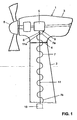
- wind power plant 1 has in a conventional manner a nacelle 3 which is rotatably mounted about a vertical axis on a mast 2.
- the storage can be done on a known pivot bearing 4.
- the nacelle 3 has a rotor 6, which is connected to generate electric current with a generator 5, which is arranged in the nacelle 3.
- the generator 5 is connected at a connection 9 to a first end 7 a of a cable 7.
- the cable 7 is connected to an assembly, not shown, or the like.
- the cable 7 is substantially torsionally rigid, but flexurally flexible. It preferably runs within the mast 2 over the entire height or over part of the mast 2.
- the cable 7 is fastened to a support element 11. This is fastened to the generator 5 at an upper end 11a by means of a fastening part 8.
- the fastening part 8 may be a hook or otherwise a suitable fastening device.
- the fastening part 8 can also have tensioning means, for example a pulley or the like, in order to tension the support element 11.
- the lower end 7b is attached to a fixed clamping device 10.
- the required clamping force can be comparatively small.
- the clamping force will be higher according to the weight of the cable 7.
- the clamping force is chosen in particular so that the support element 11 extends in a substantially straight line.
- the cable 7 is designed as serpentine as shown and has a plurality of sheets 15, which are preferably approximately semi-circular arc. But there are also deviations from this form possible. Between each two adjacent arcs 15, the cable 7 is connected to the support element 11 at an attachment point 16.
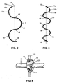
- the attachment can according to FIG. 4 be realized by means of a connecting element 12 which has a passage 17 for the cable 7 and a wedge-shaped recess 13 extending transversely thereto for the support element 11.
- a clamp 14 the support member 11 may be connected to the connecting means 12.
- another attachment such as an adhesive bond, a screw or a press connection.
- the connecting means 12 according to FIG.
- connection point between the support element 11 and the cable 7 should preferably be largely punctiform.
- the connection point is according to FIG. 2 in an attachment point 16 or 16 ', which forms a turning point with respect to the course of the cable 7 At this point, one arch passes into the other.
- the radius of the arches 15 depends in particular on the diameter of the cable 7.
- the diameter of the arcs 15 is preferably at least 8 times greater than the diameter of the cable 7.
- Suitable ratios can be determined by calculation or in a practical experiment
- the sheets 15 are in a plane.
- the sheet 15 according to FIG. 3 each be bent spirally. These bends allow the said torsion.
- a comparison of FIGS. 2 and 3 shows the following: In point 15a, a bend with an axis rotation of 90 ° is possible. In point 15b there is a bend with an axis rotation of 45 °. In point 15c the cable load is minimal, the bending direction remains the same. Only the radius is smaller here.
Landscapes
- Engineering & Computer Science (AREA)
- Life Sciences & Earth Sciences (AREA)
- Sustainable Development (AREA)
- Sustainable Energy (AREA)
- Chemical & Material Sciences (AREA)
- Combustion & Propulsion (AREA)
- Mechanical Engineering (AREA)
- General Engineering & Computer Science (AREA)
- Power Engineering (AREA)
- Wind Motors (AREA)
- Cultivation Receptacles Or Flower-Pots, Or Pots For Seedlings (AREA)
Description
- Die Erfindung betrifft ein Kabel mit einer Aufhängevorrichtung, wobei das Kabel im Wesentlichen torsionssteif und biegeflexibel ist und die Aufhängevorrichtung so ausgebildet ist, dass das Kabel mit zwei gegeneinander axial begrenzt drehbaren Teilen verbindbar ist.
- Kabel, die im Wesentlichen torsionssteif und biegeflexibel sind, sind beispielsweise als abgeschirmte Koaxialkabel oder auch als Glasfaserkabel bekannt Elektrische Kabel müssen beispielsweise als Signalkabel oder Leistungskabel vielfach mit einer Abschirmung gegen elektrische und magnetische Felder geschützt werden. Diese Abschirmung wird beispielsweise als Drahtgeflecht in Schlauchform um elektrische Leitungen realisiert. Um die Abschirmung ist in der Regel ein Kabelmantel aus extrudiertem polymerem Werkstoff gelegt. Insbesondere bei Koaxialkabeln aus der Hochfrequenztechnik sind solche Geflechtsschläuche als Aussenleiter um einen zentralen Innenleiter und einem Dielektrikum bekannt Glasfaserkabel werden vor allem für die Signalübertragung verwendet. Diese sind bekanntlich sehr torsionssteif und vergleichsweise biegeflexibel. An die Verlegung solcher Glasfaserkabel sind hohe Anforderungen gestellt.
- Elektrische Kabel müssen bei gewissen Anwendungen so installiert werden, dass sie gegeneinander axial drehende Teile oder Baugruppen verbinden. Aufgrund der gegeneinander drehbaren Baugruppen muss das Kabel entsprechend.torsionsflexibel sein. Da aber beispielsweise abgeschirmte Koaxialkabel und auch Glasfaserkabel sehr torsionssteif sind, würde eine solche Drehung der Baugruppen gegeneinander das Kabel beschädigen. Ein Beispiel ist insbesondere bei Windkraftwerken gegeben. Diese besitzen eine Gondel, die auf einem Mast gelagert ist und die sich auf die Windrichtung ausrichten muss. Zwischen Gondel und feststehendem Mast entsteht somit eine Torsionsbewegung. Steuer- und Leistungskabel müssen von der um ein paar Drehungen im Uhrzeigersinn oder Gegenuhrzeigersinn rotierenden Gondel in den Mast geführt werden. Von den Kabeln muss eine Torsion von etwa +/- 100° pro Meter aufgenommen werden können. Üblicherweise werden bei solchen torsionsflexiblen Anforderungen die Kabel um die Torsionsachse gewendelt oder es werden Schleifring-Kontaktierungen eingesetzt.
- Bei der Windkraftmaschine nach der
EP-A-1 921311 ist ein elektrisches Kabel einer Aufhängevorrichtung mit einer Schleife an der Gondel befestigt. Die Schleife ermöglicht eine Rotation der Gondel. - Bei der Windkraftmaschine nach der
JP-A 2008-298051 - Das Dokument
US2004/0094965 A wird als nächtsliegender Stand der Technik augesehen. - Die genannte Schleifring-Kontaktierung ist bei vieladrigen Kabeln sehr aufwendig und zudem störungsanfällig. Bei dicken und schweren Kabeln ist eine gewendelte Anordnung problematisch und ebenfalls aufwendig.
- Der Erfindung liegt die Aufgabe zugrunde, ein Kabel mit einer Aufhängevorrichtung gemäss Oberbegriff des Anspruchs 1 so auszubilden, dass die oben genannten Nachteile vermieden sind.
- Die Aufgabe ist gemäss Anspruch 1 dadurch gelöst, dass das Kabel schlangenlinienförmig ausgelegt ist und dass die Aufhängevorrichtung ein längliches und torsionsflexibles sowie in Längsrichtung spannbares Tragelement aufweist, das jeweils zwischen zwei benachbarten Biegungen des Kabels mit diesem verbunden ist.
- Es hat sich gezeigt, dass ein Kabel mit einer Aufhängevorrichtung gemäss der Erfindung ohne Beschädigung Torsionsbewegungen aufnehmen kann. Das Kabel kann beispielsweise bei einem Windkraftwerk mehrere Rotationen der Gondel in einer Richtung aufnehmen. Bei dieser Anwendung kann das Kabel in Schlangenlinienform aufgehängt und die Kabelenden können oben und unten fix angeschlossen werden. Versuche haben gezeigt, dass eine Torsion, beispielsweise eine vertikale Torsion, am Kabel in Biegungen umgewandelt wird. Dies ist hier ohne Weiteres ohne Beschädigung möglich, da das Kabel wie erwähnt biegeflexibel ist. Entsprechend den Windungen bzw. den Befestigungspunkten zum Tragelement ergibt die Summe dieser Biegungen die gesamte Biegung des Kabels. Die Biegungen werden somit entsprechend den Befestigungspunkten aufgeteilt. Um einen genügenden Verdrehwinkel zu erreichen, wird entsprechend die Anzahl der Befestigungsstellen gewählt. Bei einem Windkraftwerk, bei dem der Mast sehr hoch sein kann, sind somit eine vergleichsweise hohe Anzahl von Befestigungsstellen bzw. Biegungen des Kabels möglich. Entsprechend ist ein hoher Verdrehwinkel möglich.
- Das Tragelement ist im Gegensatz zum Kabel im Wesentlichen torsionsflexibel sowie in Längsrichtung spannbar. Es kann beispielsweise als Seil oder Kette ausgebildet sein. Das Seil sollte vorzugsweise so ausgebildet sein, dass es bei einer Torsion eine möglichst minimale Längenänderung aufweist. Geeignet sind beispielsweise spiralgeflochtene Seile, beispielsweise ähnlich einem Bergseil. Möglich sind aber auch Ketten, beispielsweise Ring-Gliederketten, Kugelketten oder auch andere Ketten.
- Nach einer Weiterbildung der Erfindung ist vorgesehen, dass die Aufhängevorrichtung ein Spannmittel zum Spannen des Tragelementes aufweist. Bei einer hängenden Anordnung kann aufgrund des Gewichtes des Kabels ein solches Spannmittel weggelassen werden. Das Spannmittel kann beispielsweise eine Zugfeder oder andere geeignete Mittel aufweisen.
- Nach einer Weiterbildung der Erfindung ist vorgesehen, dass das Kabel halbkreisförmige Bogen aufweist. Solche Biegungen haben sich insbesondere bei einem elektrischen Kabel als optimal erwiesen. Die Befestigungsstellen sind dann die Wendepunkte zwischen aufeinanderfolgenden halbkreisförmigen Bogen. Das Kabel kann in diesen Befestigungsstellen jedoch auch über einen gösseren Bereich im Wesentlichen rechtwinklig zum gespannten Tragelement verlaufen. Im nicht verdrehten Zustand liegen diese Bogen in einer Ebene.
- Nach einer Weiterbildung der Erfindung ist vorgesehen, dass bei gespanntem Tragelement das Kabel Biegungen aufweist, deren Radius wenigstens 10 Mal grösser ist als der Durchmesser des Kabels. Dieses Verhältnis ist besonders vorteilhaft bei einem elektrischen Kabel und insbesondere einem abgeschirmten Koaxialkabel.
- Das Kabel kann auch ein Glasfaserkabel sein, das für die optische Signalübertragung vorgesehen ist. Die Ausrichtung kann vertikal, aber auch schräg zur Vertikalen und insbesondere auch horizontal sein.
- Das Kabel mit einer Aufhängevorrichtung gemäss der vorliegenden Erfindung eignet sich beispielsweise für die Verwendung in einem Windkraftwerk. Das Kabel verbindet hierbei die Gondel mit einer feststehenden Baugruppe. Es sind jedoch auch andere Verwendungen bzw. Anwendungen denkbar, beispielsweise in einem Bagger, einem Roboter, einem Montageautomaten oder einem Lenksystem. Entsprechend wird dann die Befestigung des Tragelementes gewählt. Diese Befestigung mit Spannvorrichtung kann beispielsweise über einen Haken, ein Gewinde, einen Flaschenzug oder über eine Hebelkonstruktion erfolgen. Die Spannvorrichtung kann an einem oberen, unteren, oder auch an beiden Enden des Tragelementes vorgesehen sein. Die Aufhängevorrichtung wird jeweils so montiert, dass das Tragelement in einer geraden Linie verläuft. Bei einer vertikalen Montage muss es nicht oder nur leicht gespannt werden. Bei anderen Ausrichtungen muss das Tragelement jedoch entsprechend der quer zur Längserstreckung gerichteten Gewichtskraft des Kabels gespannt werden. Vorzugsweise ist eine entsprechende Spannvorrichtung einstellbar.
- Weitere vorteilhafte Merkmale ergeben sich aus den abhängigen Patentansprüchen, der nachfolgenden Beschreibung sowie der Zeichnung.
- Ein Ausführungsbeispiel der Erfindung ist nachfolgend anhand der Zeichnung näher erläutert.
- Es zeigen:
- Fig. 1
- Ein Schnitt durch einen oberen Teil eines Windkraftwerkes,
- Fig. 2
- schematisch ein Abschnitt eines ausgelegten und nicht verdrehten Kabels,
- Fig. 3
- das Kabel gemäss
Figur 2 , jedoch nach einer Torsion und - Fig. 4
- schematisch eine räumliche Darstellung eines Befestigungsmittels, mit dem das Tragelement mit dem Kabel verbunden ist.
- Das in
Figur 1 gezeigte Windkraftwerk 1 besitzt in an sich üblicher Weise eine Gondel 3, die um eine vertikale Achse rotierbar auf einem Mast 2 gelagert ist Die Lagerung kann an einem an sich bekannten Drehlager 4 erfolgen. Die Gondel 3 besitzt einen Rotor 6, der zur Erzeugung von elektrischem Strom mit einem Generator 5 verbunden ist, welcher in der Gondel 3 angeordnet ist. Zur Übertragung der elektrischen Leistung und zur Steuerung ist der Generator 5 an einem Anschluss 9 mit einem ersten Ende 7a eines Kabels 7 verbunden. An einem anderen Ende 7b ist das Kabel 7 mit einer hier nicht gezeigten Baugruppe oder dergleichen verbunden. Das Kabel 7 ist im Wesentlichen torsionssteif, jedoch biegeflexibel. Es verläuft vorzugsweise innerhalb des Mastes 2 über die ganze Höhe oder über einen Teil des Mastes 2. - Das Kabel 7 ist an einem Tragelement 11 befestigt. Dieses ist an einem oberen Ende 11a mittels eines Befestigungsteils 8 am Generator 5 befestigt. Das Befestigungsteil 8 kann ein Haken oder sonst eine geeignete Befestigungsvorrichtung sein. Das Befestigungsteil 8 kann auch Spannmittel, beispielsweise ein Flaschenzug oder dergleichen aufweisen, um das Tragelement 11 zu spannen. Möglich ist auch eine Ausbildung, bei welcher das untere Ende 7b an einer ortsfesten Spannvorrichtung 10 befestigt ist. Bei einer vertikalen Ausrichtung des Kabels 7 gemäss
Figur 1 kann die erforderliche Spannkraft vergleichsweise klein sein. Bei einer ebenfalls möglichen geneigten oder horizontalen Ausrichtung wird die Spannkraft entsprechend dem Gewicht des Kabels 7 höher sein. Die Spannkraft wird insbesondere so gewählt, dass das Tragelement 11 in einer im Wesentlichen geraden Linie verläuft. - Das Kabel 7 ist wie ersichtlich schlangenlinienförmig ausgelegt und besitzt mehrere Bogen 15, die vorzugsweise angenäherte halbkreisförmige Bogen sind. Es sind hier aber auch Abweichungen von dieser Form möglich. Jeweils zwischen zwei benachbarten Bögen 15 ist das Kabel 7 an einer Befestigungsstelle 16 mit dem Tragelement 11 verbunden. Die Befestigung kann gemäss
Figur 4 mittels eines Verbindungselementes 12 realisiert sein, das einen Durchgang 17 für das Kabel 7 und eine hierzu quer verlaufende keilförmige Vertiefung 13 für das Tragelement 11 aufweist. Mittels einer Klammer 14 kann das Tragelement 11 mit dem Verbindungsmittel 12 verbunden sein. Denkbar ist aber auch eine andere Befestigung, beispielsweise eine Klebeverbindung, eine Schraubverbindung oder eine Pressverbindung. Das Verbindungsmittel 12 gemässFigur 4 kann ein separat hergestelltes Spritzgussteil sein oder kann am Kabel 7 und/oder am Tragelement 11 angespritzt sein. Möglich ist auch eine Verbindung durch einen geeigneten Knoten. Die Verbindungsstelle zwischen dem Tragelement 11 und dem Kabel 7 sollte aber vorzugsweise weitgehend punktuell sein. Die Verbindungsstelle befindet sich gemässFigur 2 in einem Befestigungspunkt 16 bzw. 16', der bezüglich des Verlaufs des Kabels 7 einen Wendepunkt bildet An diesem geht der eine Bogen in den anderen über. - Der Radius der Bögen 15 richtet sich insbesondere nach dem Durchmesser des Kabels 7. Bei einem elektrischen Kabel und insbesondere einem abgeschirmten Koaxialkabel ist der Durchmesser der Bögen 15 jeweils vorzugsweise mindestens 8 Mal grösser als der Durchmesser des Kabels 7. Es sind hier aber auch andere Verhältnisse denkbar. Geeignete Verhältnisse können rechnerisch oder in einem praktischen Versuch ermittelt werden
- Im nicht tordierten Zustand befinden sich die Bögen 15 in einer Ebene. Bei einer Verdrehung können die Bogen 15 gemäss
Figur 3 jeweils spiralförmig gebogen werden. Diese Biegungen ermöglichen die genannte Torsion. Ein Vergleich derFiguren 2 und 3 zeigt folgendes: In Punkt 15a ist eine Biegung mit einer Achsdrehung von 90° möglich. Im Punkt 15b erfolgt eine Biegung mit einer Achsdrehung um 45°. Im Punkt 15c ist die Kabelbelastung minimal, die Biegerichtung bleibt gleich. Lediglich der Radius wird hier kleiner. -
- 1
- Windkraftwerk
- 2
- Mast
- 3
- Gondel
- 4
- Drehlager
- 5
- Generator
- 6
- Rotor
- 7
- Kabel
- 8
- Befestigungsteil
- 9
- Anschluss
- 10
- Spannvorrichtung
- 11
- Tragelement
- 12
- Verbindungsmittel
- 13
- Vertiefung
- 14
- Klammer
- 15
- Bogen
- 16
- Befestigungspunkt
- 17
- Durchgang
Claims (15)
- Kabel mit einer Aufhängevorrichtung, wobei das Kabel im wesentlichen torsionssteif und im wesentlichen biegeflexibel ist und die Aufhängevorrichtung so ausgebildet ist, dass das Kabel mit zwei sich gegeneinander axial begrenzt drehbaren Teilen (2, 3) verbindbar ist, dadurch gekennzeichnet, dass das Kabel schlangenlinienförmig ausgelegt ist und dass die Aufhängevorrichtung ein längliches und torsionsflexibles sowie in Längsrichtung spannbares Tragelement (11) aufweist, das jeweils zwischen zwei benachbarten Biegungen (15) des Kabels mit diesem verbunden ist
- Kabel mit einer Aufhängevorrichtung nach Anspruch 1, dadurch gekennzeichnet, dass das Tragelement (11) ein Seil oder eine Kette ist.
- Kabel mit einer Aufhängevorrichtung nach Anspruch 1 oder 2, dadurch gekennzeichnet, dass die Aufhängevorrichtung ein Spannmittel (10) zum Spannen des Tragelementes (11) aufweist.
- Kabel mit einer Aufhängevorrichtung nach einem der Ansprüche 1 bis 3, dadurch gekennzeichnet, dass das Kabel halbkreisförmige Bogen (15')anfweist
- Kabel mit einer Aufhängevorrichtung nach einem der Ansprüche 1 bis 4, dadurch gekennzeichnet, dass das Tragelement (11) im gespannten Zustand mit dem Kabel jeweils in einem Bereich (16') verbunden ist, der im Wesentlichen rechtwinklig zum Tragelement verläuft.
- Kabel mit einer Aufhängevorrichtung nach einem der Ansprüche 1 bis 5, dadurch gekennzeichnet, dass das Tragelement (11) im gespannten Zustand jeweils an einem Wendepunkt (16') des Kabels mit diesem verbunden ist.
- Kabel mit einer Aufhängevorrichtung nach einem der Ansprüche 1 bis 6, dadurch gekennzeichnet, dass bei gespanntem Tragelement (11) das Kabel Biegungen (15') aufweist, deren Radius wenigstens acht Mal grösser ist als der Durchmesser des Kabels.
- Kabel mit einer Aufhängevorrichtung nach einem der Ansprüche 1 bis 7, dadurch gekennzeichnet, dass das Kabel ein elektrisches Kabel ist
- Kabel mit einer Aufhängevorrichtung nach Anspruch 8, dadurch gekennzeichnet, dass das Kabel ein abgeschirmtes Koaxialkabel ist.
- Kabel mit einer. Aufhängevorrichtung nach einem der Ansprüche 1bis 7, dadurch gekennzeichnet, dass das Kabel ein Glasfaserkabel ist.
- Kabel mit einer Aufhängevorrichtung nach einem der Ansprüche 1 bis 10, dadurch gekennzeichnet, dass die Aufhängevorrichtung an einem oberen Ende (11a) vertikal hängend befestigbar ist.
- Kabel mit einer Aufhängevorrichtung nach einem der Ansprüche 1 bis 10, dadurch gekennzeichnet, dass die Aufhängevorrichtung geneigt zur Vertikalen befestigbar und spannbar ist.
- Verwendung des Kabels und der Aufhängevorrichtung nach einem der Ansprüche 1 bis 12 in einem Windkraftwerk (1), wobei das Kabel an einem oberen Ende mit dem Generator (5') verbunden ist
- Verwendung des Kabels nach Anspruch 13, dadurch gekennzeichnet, dass der Generator (5')in einer Gondel (3) angeordnet ist, die bezüglich eines Mastes (2) begrenzt drehbar ist
- Windkraftwerk mit einem Kabel und einer Aufhängevorrichtung nach einem der Ansprüche 1 bis 12, dadurch gekennzeichnet, dass sich das Kabel über eine wesentliche Länge des Mastes (2) ersteckt
Applications Claiming Priority (2)
| Application Number | Priority Date | Filing Date | Title |
|---|---|---|---|
| CH00812/09A CH701122A8 (de) | 2009-05-27 | 2009-05-27 | Kabel mit einer aufhängevorrichtung, verwendung dieses kabels und der aufhängevorrichtung in einem windkraftwerk sowie windkraftwerk mit einem solchen kabel und einer solchen aufhängevorrichtung. |
| PCT/CH2010/000125 WO2010135844A1 (de) | 2009-05-27 | 2010-05-10 | Kabel mit einer aufhängevorrichtung, verwendung dieses kabels und der aufhängevorrichtung in einem windkraftwerk sowie windkraftwerk mit einem solchen kabel und einer solchen aufhängevorrichtung |
Publications (3)
| Publication Number | Publication Date |
|---|---|
| EP2435698A1 EP2435698A1 (de) | 2012-04-04 |
| EP2435698B1 true EP2435698B1 (de) | 2013-04-03 |
| EP2435698B8 EP2435698B8 (de) | 2013-06-19 |
Family
ID=41800552
Family Applications (1)
| Application Number | Title | Priority Date | Filing Date |
|---|---|---|---|
| EP10718427.7A Not-in-force EP2435698B8 (de) | 2009-05-27 | 2010-05-10 | Kabel mit einer aufhängevorrichtung, verwendung dieses kabels und der aufhängevorrichtung in einem windkraftwerk sowie windkraftwerk mit einem solchen kabel und einer solchen aufhängevorrichtung |
Country Status (5)
| Country | Link |
|---|---|
| EP (1) | EP2435698B8 (de) |
| CH (1) | CH701122A8 (de) |
| DK (1) | DK2435698T3 (de) |
| ES (1) | ES2417809T3 (de) |
| WO (1) | WO2010135844A1 (de) |
Cited By (1)
| Publication number | Priority date | Publication date | Assignee | Title |
|---|---|---|---|---|
| CN105408628A (zh) * | 2013-07-18 | 2016-03-16 | Ssb风系统两合公司 | 风力发电设备的转子 |
Families Citing this family (1)
| Publication number | Priority date | Publication date | Assignee | Title |
|---|---|---|---|---|
| CN108999760B (zh) * | 2018-08-16 | 2023-10-27 | 远景能源有限公司 | 风机扭缆马鞍装置 |
Family Cites Families (4)
| Publication number | Priority date | Publication date | Assignee | Title |
|---|---|---|---|---|
| EP1149449A2 (de) * | 1998-12-17 | 2001-10-31 | Dan-Control Engineering A/S | Windkraftanlage mit kabelhalterung , kabelhalterung und halterungstraggestelldafür. |
| US7323636B1 (en) * | 2006-06-09 | 2008-01-29 | Preformed Line Products Company | Aerial cable spacer with cable retaining arm having non-rectangular plus-shaped cross section and angled pawl locking member |
| FI20060988A0 (fi) * | 2006-11-09 | 2006-11-09 | Winwind Oy | Tuulivoimala |
| JP2008298051A (ja) | 2007-06-04 | 2008-12-11 | Ebara Corp | 風力発電装置 |
-
2009
- 2009-05-27 CH CH00812/09A patent/CH701122A8/de not_active Application Discontinuation
-
2010
- 2010-05-10 WO PCT/CH2010/000125 patent/WO2010135844A1/de not_active Ceased
- 2010-05-10 ES ES10718427T patent/ES2417809T3/es active Active
- 2010-05-10 EP EP10718427.7A patent/EP2435698B8/de not_active Not-in-force
- 2010-05-10 DK DK10718427.7T patent/DK2435698T3/da active
Cited By (1)
| Publication number | Priority date | Publication date | Assignee | Title |
|---|---|---|---|---|
| CN105408628A (zh) * | 2013-07-18 | 2016-03-16 | Ssb风系统两合公司 | 风力发电设备的转子 |
Also Published As
| Publication number | Publication date |
|---|---|
| DK2435698T3 (da) | 2013-07-08 |
| CH701122A8 (de) | 2012-02-15 |
| ES2417809T3 (es) | 2013-08-09 |
| EP2435698B8 (de) | 2013-06-19 |
| EP2435698A1 (de) | 2012-04-04 |
| WO2010135844A1 (de) | 2010-12-02 |
| CH701122A1 (de) | 2010-11-30 |
Similar Documents
| Publication | Publication Date | Title |
|---|---|---|
| DE102007017015B4 (de) | Leitungshaltevorrichtung | |
| DE102011076941A1 (de) | Turm für eine Windturbine | |
| DE3640919C2 (de) | ||
| DE102012002093A1 (de) | Leitungsführungssystem zur Aufnahme und Führung von Versorgungsleitungen sowie Werkzeugmaschine | |
| EP2762723B1 (de) | Windenergieanlage mit Turm und Kabeln im Turm | |
| EP2435698A1 (de) | Kabel mit einer aufhängevorrichtung, verwendung dieses kabels und der aufhängevorrichtung in einem windkraftwerk sowie windkraftwerk mit einem solchen kabel und einer solchen aufhängevorrichtung | |
| EP2695261A2 (de) | ENERGIEFÜHRUNGSVORRICHTUNG FÜR GROßE VERDREHWINKEL | |
| EP1398850B1 (de) | Erdleitungsbride | |
| DE2915698A1 (de) | Wendelfoermig vorgeformte drahtgreifende vorrichtung | |
| EP4005046A1 (de) | Energiekabelanordung für offshore-windparks | |
| DE102016120313B4 (de) | Energieführungskette mit Verstärkungselement | |
| WO2009018793A2 (de) | Aktor | |
| EP1389707B1 (de) | Leitungsführung bei einem Deckenstativ mit verschwenkbaren Stativabschnitten | |
| DE202019105125U1 (de) | Drehführung für eine oder mehrere Leitungen | |
| DE102010031722B4 (de) | Umlenkmodul und System zum Spannen eines Leiterseils auf Hochspannungsmasten | |
| EP0212643B1 (de) | Seilabspannklemme | |
| DE60201309T2 (de) | Anordnung zum Umwandeln einer hin- und hergehenden Bewegung in eine schwingende Bewegung | |
| DE102025104545B3 (de) | Vorrichtung zum Anbringen eines Schutzbands um einen Kabelbaum sowie Verfahren | |
| DE2810700C2 (de) | Einrichtung zum Aufhängen von Freileitungsseilen an Stützmasten o.dgl. | |
| WO2000070382A1 (de) | Hochspannungsfreileitung mit einem an einem leiter- oder erdseil angebrachten optischen kabel | |
| DE102014218943A1 (de) | Wagenübergangssystem zur Führung wenigstens eines Versorgungskabels | |
| DE4424007A1 (de) | Freileitungsseile | |
| DE102010031449A1 (de) | Rohrleitungsanordnung | |
| DE102009024539A1 (de) | Halterung für Leiterseil | |
| EP0848657B1 (de) | Anordnung zur führung von drähten |
Legal Events
| Date | Code | Title | Description |
|---|---|---|---|
| PUAI | Public reference made under article 153(3) epc to a published international application that has entered the european phase |
Free format text: ORIGINAL CODE: 0009012 |
|
| 17P | Request for examination filed |
Effective date: 20111001 |
|
| AK | Designated contracting states |
Kind code of ref document: A1 Designated state(s): AL AT BE BG CH CY CZ DE DK EE ES FI FR GB GR HR HU IE IS IT LI LT LU LV MC MK MT NL NO PL PT RO SE SI SK SM TR |
|
| DAX | Request for extension of the european patent (deleted) | ||
| GRAP | Despatch of communication of intention to grant a patent |
Free format text: ORIGINAL CODE: EPIDOSNIGR1 |
|
| GRAS | Grant fee paid |
Free format text: ORIGINAL CODE: EPIDOSNIGR3 |
|
| GRAA | (expected) grant |
Free format text: ORIGINAL CODE: 0009210 |
|
| AK | Designated contracting states |
Kind code of ref document: B1 Designated state(s): AL AT BE BG CH CY CZ DE DK EE ES FI FR GB GR HR HU IE IS IT LI LT LU LV MC MK MT NL NO PL PT RO SE SI SK SM TR |
|
| REG | Reference to a national code |
Ref country code: GB Ref legal event code: FG4D Free format text: NOT ENGLISH |
|
| REG | Reference to a national code |
Ref country code: AT Ref legal event code: REF Ref document number: 604901 Country of ref document: AT Kind code of ref document: T Effective date: 20130415 Ref country code: CH Ref legal event code: EP |
|
| REG | Reference to a national code |
Ref country code: CH Ref legal event code: NV Representative=s name: RENTSCH PARTNER AG, CH |
|
| REG | Reference to a national code |
Ref country code: IE Ref legal event code: FG4D Free format text: LANGUAGE OF EP DOCUMENT: GERMAN |
|
| RAP2 | Party data changed (patent owner data changed or rights of a patent transferred) |
Owner name: HUBER + SUHNER AG |
|
| REG | Reference to a national code |
Ref country code: DE Ref legal event code: R096 Ref document number: 502010002860 Country of ref document: DE Effective date: 20130529 |
|
| REG | Reference to a national code |
Ref country code: DK Ref legal event code: T3 |
|
| REG | Reference to a national code |
Ref country code: ES Ref legal event code: FG2A Ref document number: 2417809 Country of ref document: ES Kind code of ref document: T3 Effective date: 20130809 |
|
| PG25 | Lapsed in a contracting state [announced via postgrant information from national office to epo] |
Ref country code: SI Free format text: LAPSE BECAUSE OF FAILURE TO SUBMIT A TRANSLATION OF THE DESCRIPTION OR TO PAY THE FEE WITHIN THE PRESCRIBED TIME-LIMIT Effective date: 20130403 |
|
| REG | Reference to a national code |
Ref country code: NL Ref legal event code: VDEP Effective date: 20130403 |
|
| REG | Reference to a national code |
Ref country code: LT Ref legal event code: MG4D |
|
| PG25 | Lapsed in a contracting state [announced via postgrant information from national office to epo] |
Ref country code: NO Free format text: LAPSE BECAUSE OF FAILURE TO SUBMIT A TRANSLATION OF THE DESCRIPTION OR TO PAY THE FEE WITHIN THE PRESCRIBED TIME-LIMIT Effective date: 20130703 Ref country code: FI Free format text: LAPSE BECAUSE OF FAILURE TO SUBMIT A TRANSLATION OF THE DESCRIPTION OR TO PAY THE FEE WITHIN THE PRESCRIBED TIME-LIMIT Effective date: 20130403 Ref country code: GR Free format text: LAPSE BECAUSE OF FAILURE TO SUBMIT A TRANSLATION OF THE DESCRIPTION OR TO PAY THE FEE WITHIN THE PRESCRIBED TIME-LIMIT Effective date: 20130704 Ref country code: LT Free format text: LAPSE BECAUSE OF FAILURE TO SUBMIT A TRANSLATION OF THE DESCRIPTION OR TO PAY THE FEE WITHIN THE PRESCRIBED TIME-LIMIT Effective date: 20130403 Ref country code: NL Free format text: LAPSE BECAUSE OF FAILURE TO SUBMIT A TRANSLATION OF THE DESCRIPTION OR TO PAY THE FEE WITHIN THE PRESCRIBED TIME-LIMIT Effective date: 20130403 Ref country code: IS Free format text: LAPSE BECAUSE OF FAILURE TO SUBMIT A TRANSLATION OF THE DESCRIPTION OR TO PAY THE FEE WITHIN THE PRESCRIBED TIME-LIMIT Effective date: 20130803 Ref country code: PT Free format text: LAPSE BECAUSE OF FAILURE TO SUBMIT A TRANSLATION OF THE DESCRIPTION OR TO PAY THE FEE WITHIN THE PRESCRIBED TIME-LIMIT Effective date: 20130805 Ref country code: SE Free format text: LAPSE BECAUSE OF FAILURE TO SUBMIT A TRANSLATION OF THE DESCRIPTION OR TO PAY THE FEE WITHIN THE PRESCRIBED TIME-LIMIT Effective date: 20130403 |
|
| PG25 | Lapsed in a contracting state [announced via postgrant information from national office to epo] |
Ref country code: BG Free format text: LAPSE BECAUSE OF FAILURE TO SUBMIT A TRANSLATION OF THE DESCRIPTION OR TO PAY THE FEE WITHIN THE PRESCRIBED TIME-LIMIT Effective date: 20130703 Ref country code: HR Free format text: LAPSE BECAUSE OF FAILURE TO SUBMIT A TRANSLATION OF THE DESCRIPTION OR TO PAY THE FEE WITHIN THE PRESCRIBED TIME-LIMIT Effective date: 20130403 Ref country code: PL Free format text: LAPSE BECAUSE OF FAILURE TO SUBMIT A TRANSLATION OF THE DESCRIPTION OR TO PAY THE FEE WITHIN THE PRESCRIBED TIME-LIMIT Effective date: 20130403 Ref country code: LV Free format text: LAPSE BECAUSE OF FAILURE TO SUBMIT A TRANSLATION OF THE DESCRIPTION OR TO PAY THE FEE WITHIN THE PRESCRIBED TIME-LIMIT Effective date: 20130403 Ref country code: CY Free format text: LAPSE BECAUSE OF FAILURE TO SUBMIT A TRANSLATION OF THE DESCRIPTION OR TO PAY THE FEE WITHIN THE PRESCRIBED TIME-LIMIT Effective date: 20130403 |
|
| BERE | Be: lapsed |
Owner name: HUBER + SUHNER A.G. Effective date: 20130531 |
|
| PG25 | Lapsed in a contracting state [announced via postgrant information from national office to epo] |
Ref country code: CZ Free format text: LAPSE BECAUSE OF FAILURE TO SUBMIT A TRANSLATION OF THE DESCRIPTION OR TO PAY THE FEE WITHIN THE PRESCRIBED TIME-LIMIT Effective date: 20130403 Ref country code: SK Free format text: LAPSE BECAUSE OF FAILURE TO SUBMIT A TRANSLATION OF THE DESCRIPTION OR TO PAY THE FEE WITHIN THE PRESCRIBED TIME-LIMIT Effective date: 20130403 Ref country code: MC Free format text: LAPSE BECAUSE OF FAILURE TO SUBMIT A TRANSLATION OF THE DESCRIPTION OR TO PAY THE FEE WITHIN THE PRESCRIBED TIME-LIMIT Effective date: 20130403 Ref country code: EE Free format text: LAPSE BECAUSE OF FAILURE TO SUBMIT A TRANSLATION OF THE DESCRIPTION OR TO PAY THE FEE WITHIN THE PRESCRIBED TIME-LIMIT Effective date: 20130403 |
|
| PLBE | No opposition filed within time limit |
Free format text: ORIGINAL CODE: 0009261 |
|
| STAA | Information on the status of an ep patent application or granted ep patent |
Free format text: STATUS: NO OPPOSITION FILED WITHIN TIME LIMIT |
|
| REG | Reference to a national code |
Ref country code: IE Ref legal event code: MM4A |
|
| PG25 | Lapsed in a contracting state [announced via postgrant information from national office to epo] |
Ref country code: RO Free format text: LAPSE BECAUSE OF FAILURE TO SUBMIT A TRANSLATION OF THE DESCRIPTION OR TO PAY THE FEE WITHIN THE PRESCRIBED TIME-LIMIT Effective date: 20130403 Ref country code: IT Free format text: LAPSE BECAUSE OF FAILURE TO SUBMIT A TRANSLATION OF THE DESCRIPTION OR TO PAY THE FEE WITHIN THE PRESCRIBED TIME-LIMIT Effective date: 20130403 Ref country code: BE Free format text: LAPSE BECAUSE OF NON-PAYMENT OF DUE FEES Effective date: 20130531 |
|
| REG | Reference to a national code |
Ref country code: FR Ref legal event code: ST Effective date: 20140131 |
|
| 26N | No opposition filed |
Effective date: 20140106 |
|
| REG | Reference to a national code |
Ref country code: DE Ref legal event code: R097 Ref document number: 502010002860 Country of ref document: DE Effective date: 20140106 |
|
| PG25 | Lapsed in a contracting state [announced via postgrant information from national office to epo] |
Ref country code: IE Free format text: LAPSE BECAUSE OF NON-PAYMENT OF DUE FEES Effective date: 20130510 |
|
| PG25 | Lapsed in a contracting state [announced via postgrant information from national office to epo] |
Ref country code: FR Free format text: LAPSE BECAUSE OF NON-PAYMENT OF DUE FEES Effective date: 20130603 |
|
| PG25 | Lapsed in a contracting state [announced via postgrant information from national office to epo] |
Ref country code: MT Free format text: LAPSE BECAUSE OF FAILURE TO SUBMIT A TRANSLATION OF THE DESCRIPTION OR TO PAY THE FEE WITHIN THE PRESCRIBED TIME-LIMIT Effective date: 20130403 |
|
| PG25 | Lapsed in a contracting state [announced via postgrant information from national office to epo] |
Ref country code: SM Free format text: LAPSE BECAUSE OF FAILURE TO SUBMIT A TRANSLATION OF THE DESCRIPTION OR TO PAY THE FEE WITHIN THE PRESCRIBED TIME-LIMIT Effective date: 20130403 |
|
| PG25 | Lapsed in a contracting state [announced via postgrant information from national office to epo] |
Ref country code: TR Free format text: LAPSE BECAUSE OF FAILURE TO SUBMIT A TRANSLATION OF THE DESCRIPTION OR TO PAY THE FEE WITHIN THE PRESCRIBED TIME-LIMIT Effective date: 20130403 |
|
| PG25 | Lapsed in a contracting state [announced via postgrant information from national office to epo] |
Ref country code: LU Free format text: LAPSE BECAUSE OF NON-PAYMENT OF DUE FEES Effective date: 20130510 Ref country code: MK Free format text: LAPSE BECAUSE OF FAILURE TO SUBMIT A TRANSLATION OF THE DESCRIPTION OR TO PAY THE FEE WITHIN THE PRESCRIBED TIME-LIMIT Effective date: 20130403 Ref country code: HU Free format text: LAPSE BECAUSE OF FAILURE TO SUBMIT A TRANSLATION OF THE DESCRIPTION OR TO PAY THE FEE WITHIN THE PRESCRIBED TIME-LIMIT; INVALID AB INITIO Effective date: 20100510 |
|
| REG | Reference to a national code |
Ref country code: AT Ref legal event code: MM01 Ref document number: 604901 Country of ref document: AT Kind code of ref document: T Effective date: 20150510 |
|
| PGFP | Annual fee paid to national office [announced via postgrant information from national office to epo] |
Ref country code: CH Payment date: 20160527 Year of fee payment: 7 Ref country code: ES Payment date: 20160526 Year of fee payment: 7 Ref country code: GB Payment date: 20160527 Year of fee payment: 7 Ref country code: DE Payment date: 20160527 Year of fee payment: 7 |
|
| PG25 | Lapsed in a contracting state [announced via postgrant information from national office to epo] |
Ref country code: AT Free format text: LAPSE BECAUSE OF NON-PAYMENT OF DUE FEES Effective date: 20150510 |
|
| PGFP | Annual fee paid to national office [announced via postgrant information from national office to epo] |
Ref country code: DK Payment date: 20160525 Year of fee payment: 7 |
|
| REG | Reference to a national code |
Ref country code: CH Ref legal event code: PCAR Free format text: NEW ADDRESS: BELLERIVESTRASSE 203 POSTFACH, 8034 ZUERICH (CH) |
|
| REG | Reference to a national code |
Ref country code: DE Ref legal event code: R119 Ref document number: 502010002860 Country of ref document: DE |
|
| REG | Reference to a national code |
Ref country code: CH Ref legal event code: PL |
|
| REG | Reference to a national code |
Ref country code: DK Ref legal event code: EBP Effective date: 20170531 |
|
| GBPC | Gb: european patent ceased through non-payment of renewal fee |
Effective date: 20170510 |
|
| PG25 | Lapsed in a contracting state [announced via postgrant information from national office to epo] |
Ref country code: LI Free format text: LAPSE BECAUSE OF NON-PAYMENT OF DUE FEES Effective date: 20170531 Ref country code: CH Free format text: LAPSE BECAUSE OF NON-PAYMENT OF DUE FEES Effective date: 20170531 |
|
| PG25 | Lapsed in a contracting state [announced via postgrant information from national office to epo] |
Ref country code: DE Free format text: LAPSE BECAUSE OF NON-PAYMENT OF DUE FEES Effective date: 20171201 Ref country code: GB Free format text: LAPSE BECAUSE OF NON-PAYMENT OF DUE FEES Effective date: 20170510 Ref country code: DK Free format text: LAPSE BECAUSE OF NON-PAYMENT OF DUE FEES Effective date: 20170531 |
|
| REG | Reference to a national code |
Ref country code: ES Ref legal event code: FD2A Effective date: 20180703 |
|
| PG25 | Lapsed in a contracting state [announced via postgrant information from national office to epo] |
Ref country code: ES Free format text: LAPSE BECAUSE OF NON-PAYMENT OF DUE FEES Effective date: 20170511 |
|
| PG25 | Lapsed in a contracting state [announced via postgrant information from national office to epo] |
Ref country code: AL Free format text: LAPSE BECAUSE OF FAILURE TO SUBMIT A TRANSLATION OF THE DESCRIPTION OR TO PAY THE FEE WITHIN THE PRESCRIBED TIME-LIMIT Effective date: 20130403 |