EP2434591A2 - Electrical connector with corrosion prevention - Google Patents
Electrical connector with corrosion prevention Download PDFInfo
- Publication number
- EP2434591A2 EP2434591A2 EP11190540A EP11190540A EP2434591A2 EP 2434591 A2 EP2434591 A2 EP 2434591A2 EP 11190540 A EP11190540 A EP 11190540A EP 11190540 A EP11190540 A EP 11190540A EP 2434591 A2 EP2434591 A2 EP 2434591A2
- Authority
- EP
- European Patent Office
- Prior art keywords
- connector
- electrical
- test signal
- detecting unit
- plug
- Prior art date
- Legal status (The legal status is an assumption and is not a legal conclusion. Google has not performed a legal analysis and makes no representation as to the accuracy of the status listed.)
- Withdrawn
Links
- 238000005536 corrosion prevention Methods 0.000 title 1
- 230000013011 mating Effects 0.000 claims abstract description 31
- 238000012360 testing method Methods 0.000 claims abstract description 31
- 230000003647 oxidation Effects 0.000 claims abstract description 19
- 238000007254 oxidation reaction Methods 0.000 claims abstract description 19
- 239000000463 material Substances 0.000 claims abstract description 10
- 238000001514 detection method Methods 0.000 claims description 7
- XLYOFNOQVPJJNP-UHFFFAOYSA-N water Substances O XLYOFNOQVPJJNP-UHFFFAOYSA-N 0.000 claims description 3
- 238000000034 method Methods 0.000 abstract description 5
- 230000007797 corrosion Effects 0.000 description 18
- 238000005260 corrosion Methods 0.000 description 18
- PXHVJJICTQNCMI-UHFFFAOYSA-N Nickel Chemical compound [Ni] PXHVJJICTQNCMI-UHFFFAOYSA-N 0.000 description 14
- 229910052751 metal Inorganic materials 0.000 description 9
- 239000002184 metal Substances 0.000 description 9
- PCHJSUWPFVWCPO-UHFFFAOYSA-N gold Chemical compound [Au] PCHJSUWPFVWCPO-UHFFFAOYSA-N 0.000 description 8
- 239000010931 gold Substances 0.000 description 8
- 229910052737 gold Inorganic materials 0.000 description 8
- 229910052759 nickel Inorganic materials 0.000 description 7
- 238000003780 insertion Methods 0.000 description 5
- 230000037431 insertion Effects 0.000 description 5
- 238000007747 plating Methods 0.000 description 4
- 230000001413 cellular effect Effects 0.000 description 3
- 150000002739 metals Chemical class 0.000 description 3
- 230000009467 reduction Effects 0.000 description 3
- 239000013535 sea water Substances 0.000 description 3
- 238000007789 sealing Methods 0.000 description 3
- 230000008901 benefit Effects 0.000 description 2
- 230000015556 catabolic process Effects 0.000 description 2
- 230000003247 decreasing effect Effects 0.000 description 2
- 238000006731 degradation reaction Methods 0.000 description 2
- 230000001419 dependent effect Effects 0.000 description 2
- 230000000694 effects Effects 0.000 description 2
- 150000002500 ions Chemical class 0.000 description 2
- 229910000510 noble metal Inorganic materials 0.000 description 2
- 230000037361 pathway Effects 0.000 description 2
- 230000008569 process Effects 0.000 description 2
- 230000011664 signaling Effects 0.000 description 2
- 229910045601 alloy Inorganic materials 0.000 description 1
- 239000000956 alloy Substances 0.000 description 1
- 238000013459 approach Methods 0.000 description 1
- 230000015572 biosynthetic process Effects 0.000 description 1
- 239000011248 coating agent Substances 0.000 description 1
- 238000000576 coating method Methods 0.000 description 1
- 230000003111 delayed effect Effects 0.000 description 1
- 238000011161 development Methods 0.000 description 1
- 230000018109 developmental process Effects 0.000 description 1
- 239000000428 dust Substances 0.000 description 1
- 239000003792 electrolyte Substances 0.000 description 1
- 238000006056 electrooxidation reaction Methods 0.000 description 1
- 239000012530 fluid Substances 0.000 description 1
- 238000013508 migration Methods 0.000 description 1
- 230000005012 migration Effects 0.000 description 1
- 238000003032 molecular docking Methods 0.000 description 1
- 238000012544 monitoring process Methods 0.000 description 1
- 230000035515 penetration Effects 0.000 description 1
- 239000011148 porous material Substances 0.000 description 1
Images

Classifications
-
- H—ELECTRICITY
- H01—ELECTRIC ELEMENTS
- H01R—ELECTRICALLY-CONDUCTIVE CONNECTIONS; STRUCTURAL ASSOCIATIONS OF A PLURALITY OF MUTUALLY-INSULATED ELECTRICAL CONNECTING ELEMENTS; COUPLING DEVICES; CURRENT COLLECTORS
- H01R13/00—Details of coupling devices of the kinds covered by groups H01R12/70 or H01R24/00 - H01R33/00
- H01R13/66—Structural association with built-in electrical component
- H01R13/70—Structural association with built-in electrical component with built-in switch
- H01R13/703—Structural association with built-in electrical component with built-in switch operated by engagement or disengagement of coupling parts, e.g. dual-continuity coupling part
- H01R13/7031—Shorting, shunting or bussing of different terminals interrupted or effected on engagement of coupling part, e.g. for ESD protection, line continuity
-
- C—CHEMISTRY; METALLURGY
- C23—COATING METALLIC MATERIAL; COATING MATERIAL WITH METALLIC MATERIAL; CHEMICAL SURFACE TREATMENT; DIFFUSION TREATMENT OF METALLIC MATERIAL; COATING BY VACUUM EVAPORATION, BY SPUTTERING, BY ION IMPLANTATION OR BY CHEMICAL VAPOUR DEPOSITION, IN GENERAL; INHIBITING CORROSION OF METALLIC MATERIAL OR INCRUSTATION IN GENERAL
- C23F—NON-MECHANICAL REMOVAL OF METALLIC MATERIAL FROM SURFACE; INHIBITING CORROSION OF METALLIC MATERIAL OR INCRUSTATION IN GENERAL; MULTI-STEP PROCESSES FOR SURFACE TREATMENT OF METALLIC MATERIAL INVOLVING AT LEAST ONE PROCESS PROVIDED FOR IN CLASS C23 AND AT LEAST ONE PROCESS COVERED BY SUBCLASS C21D OR C22F OR CLASS C25
- C23F13/00—Inhibiting corrosion of metals by anodic or cathodic protection
- C23F13/02—Inhibiting corrosion of metals by anodic or cathodic protection cathodic; Selection of conditions, parameters or procedures for cathodic protection, e.g. of electrical conditions
- C23F13/04—Controlling or regulating desired parameters
-
- H—ELECTRICITY
- H01—ELECTRIC ELEMENTS
- H01R—ELECTRICALLY-CONDUCTIVE CONNECTIONS; STRUCTURAL ASSOCIATIONS OF A PLURALITY OF MUTUALLY-INSULATED ELECTRICAL CONNECTING ELEMENTS; COUPLING DEVICES; CURRENT COLLECTORS
- H01R13/00—Details of coupling devices of the kinds covered by groups H01R12/70 or H01R24/00 - H01R33/00
- H01R13/64—Means for preventing incorrect coupling
- H01R13/641—Means for preventing incorrect coupling by indicating incorrect coupling; by indicating correct or full engagement
-
- C—CHEMISTRY; METALLURGY
- C23—COATING METALLIC MATERIAL; COATING MATERIAL WITH METALLIC MATERIAL; CHEMICAL SURFACE TREATMENT; DIFFUSION TREATMENT OF METALLIC MATERIAL; COATING BY VACUUM EVAPORATION, BY SPUTTERING, BY ION IMPLANTATION OR BY CHEMICAL VAPOUR DEPOSITION, IN GENERAL; INHIBITING CORROSION OF METALLIC MATERIAL OR INCRUSTATION IN GENERAL
- C23F—NON-MECHANICAL REMOVAL OF METALLIC MATERIAL FROM SURFACE; INHIBITING CORROSION OF METALLIC MATERIAL OR INCRUSTATION IN GENERAL; MULTI-STEP PROCESSES FOR SURFACE TREATMENT OF METALLIC MATERIAL INVOLVING AT LEAST ONE PROCESS PROVIDED FOR IN CLASS C23 AND AT LEAST ONE PROCESS COVERED BY SUBCLASS C21D OR C22F OR CLASS C25
- C23F2201/00—Type of materials to be protected by cathodic protection
-
- H—ELECTRICITY
- H01—ELECTRIC ELEMENTS
- H01R—ELECTRICALLY-CONDUCTIVE CONNECTIONS; STRUCTURAL ASSOCIATIONS OF A PLURALITY OF MUTUALLY-INSULATED ELECTRICAL CONNECTING ELEMENTS; COUPLING DEVICES; CURRENT COLLECTORS
- H01R24/00—Two-part coupling devices, or either of their cooperating parts, characterised by their overall structure
- H01R24/58—Contacts spaced along longitudinal axis of engagement
Definitions
- the present invention relates to an electrical connector with at least one electrical contact for electrically contacting a corresponding mating connector.
- the present invention deals with connectors having a plug detecting unit for detecting a mated state of the connector and the mating connector.
- the present invention further relates to a corresponding method for detecting a mated state.
- the present invention relates to electrical connectors for use with handheld cellular telephone units, and more particularly to a system connector that incorporates electrical contacts directly into the housing of a telephone in a manner such that the connector is sealed with respect to the external environment.
- System connectors associated with cellular telephones are used to establish and maintain electrical connection between the internal circuitry of the telephone and an external electrical circuit or device. Examples of such external devices and connection requirements are battery charging equipment, base or docking stations typically employed in automobiles to permit hands free operation of the cellular telephone unit, and headsets. Historically, such system connectors presented openings or pathways for water and debris to freely enter the interior compartment of the telephone. Typically, these penetration pathways are present in the telephone unit because there are several separate components, including a printed circuit board, a structural frame member, and a housing enclosure that must be assembled, none of which are sealed prior to assembly. As such, system connectors are generally comprised of separate pieces that are either soldered directly to the printed board or are pressed onto the printed circuit board with the housing and the frame aligning around them.
- the electrical connector may be shut down as long as no mating connector is inserted, and may only be carrying operational signals, such as audio/video signals or a connection to a battery, when the mating connector is inserted.
- a plug detecting unit which detects the presence of the mating connector.
- the monitoring whether the mating connector is inserted or not involves an electric potential present at the at least one electrical contact. Consequently, in the presence of humidity, such a constant voltage will lead to a galvanic process that results in quick and serious corrosion of the contact.
- the problem underlying the present invention is to provide an electrical connector which reduces corrosion to a level that leads to a sufficiently long product life of the device where the connector is built in.
- the invention is based on the idea that with conventional connectors where all potentials are shut down during a standby mode, the test signal itself, which has to be applied in order to detect that a plug has been inserted into the connector, causes a potential that leads to significant corrosion of the contacts.
- the inventors have recognized that this test signal has to be modified to diminish the corrosion to a degree that no problems will occur until the specified product life ends. Two different approaches are proposed, which can be applied separately or in combination:
- the idea according to the present invention can be applied to any connector having a voltage difference over any of the contacts used in a condition which can cause contact degradation by ion migration.
- the second idea which is proposed according to the present invention takes advantage of the fact that the occurring electrochemical corrosion depends on the oxidation potential of the materials involved. As generally known, corrosion is a degradation of metals as a result of electrochemical activity and requires an anode and a cathode in order to occur.
- the anode is the metal, or site, with a higher potential to oxidize, that is to lose electrons.
- the cathode is the metal, or site, with a higher potential for reduction, that is gaining of electrons. In other words, the cathode has a lower potential to oxidize than the anode.
- the measure of a material to oxidize, or to lose electrons is known as its oxidation potential. A difference between the oxidation potentials of two metals can lead to corrosion that will consume the metal that is more anodic.
- the standard oxidation potential value is a measure to determine the tendency of a metal to become a cathode or an anode with respect to another metal for corrosion to occur.
- the present invention is based on the idea that the electrical contact, which is carrying the test signal and a second reference contact, are consisting of, or are covered with, materials having a different oxidation potential.
- the positive voltage may be applied to a gold contact having an oxidation potential of +1.50 V and ground potential may be applied to a nickel electrode having an oxidation potential of -0.25 V.
- the intermittent test signal according to the present invention may comprise pulses having the form of a square wave signal or a sawtooth signal. Other suitable signal forms are, of course, also suitable. Furthermore, the polarity of the intermittent test signal may be chosen to be positive, negative or alternating.
- a particularly effective reduction of corrosion speed may be achieved by choosing the intermittent test signal in a way that high potential phases and low potential phases alternate, wherein the high potential phases have a shorter duration than the low potential phases.
- High potential in the present context may preferably amount to 1.8 volt, whereas the low potential signifies 0 V. Other values can of course be chosen as required.
- test signal and the electrode configuration can be used advantageously with a plug detecting unit that comprises a switch actuated by the mating of the two connectors, thereby altering a current path for the test signal.
- the plug detecting unit may also comprise at least two electric contacts which are short circuited by the mating connector in the mated state.
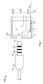
- Figure 1 shows an example of an audio/video connector system 100 comprising a connector 102 and a mating connector 104.
- the connector is an audio/video jack and the mating connector 104 is formed by an AV plug that is often called “round standard connector", “phone plug” or “TRRS connector” (Tip, Ring, Ring, Sleeve connector).
- the insertion of the mating connector 104 is detected at the side of the connector jack 102 by a detecting unit, more precisely, by a plug detecting unit, as will be described below.
- the detecting unit must not necessarily be part of the connector jack, but can also be associated with the plug, then being a "jack detecting unit".
- At least a part of the plug detecting unit may be located in an ASIC (application specific integrated circuit) which is arranged on a circuit carrier, such as a printed circuit board, within the device where the connector 102 is built in.
- ASIC application specific integrated circuit
- AV plugs are familiar to most people with a typical AV plug 104 comprising several cylindrical segments ending in a tip segment. More particularly, the body of the plug 104 usually includes a sleeve 106, one or more rings 108, 110 and a tip 112, each providing contact points with the jack 102. These plug contacts are also often referred to as poles.
- the AV jack 102 is arranged in a sealing housing 114 which blocks the ingress of humidity and debris into the device itself.
- all contacts 116 of the AV jack 102 are disconnected from any voltages, such as audio and/or video signals.
- a plug detecting unit comprises a plug detecting contact 118 which is movable upon insertion of the plug 104.
- the plug detecting contact 118 is connected to ground (GND).
- the plug detecting unit comprises a switch contact 120 that is connected to a test signal 122.
- the plug detecting contact 118 actuates a switch portion 121 of the switch contact 120, thereby, a circuit between ground and the test signal 122 is closed.
- the test signal 122 is not formed by a continuous positive or negative voltage, but by an intermittent signal.
- the test signal 122 may comprise a square wave pulse signal with an amplitude and/or pulse width that are selected so as to minimize the effects of corrosion.
- the square wave pulse signal is formed of 1.8 V pulses having a duration of one microsecond, at one second intervals.
- the materials of the switch contact 120 and the moving plug detecting contact 118 may be chosen in a way that the contact carrying the positive signal voltage is fabricated with a surface consisting of the more noble material, that is, the material having a higher oxidation potential.
- the switch contact 120 may be covered with a gold layer, whereas the contact 118 which is connected to ground is covered with a nickel layer or is fabricated from nickel.
- the standby mode of the device is interrupted and the required signals are applied to the contacts 116.
- These may be an audio and/or a video signal and, furthermore, may be dependent on the particular kind of plug connector 104, as this is well known in the art.
- Figure 2 shows the mated state of the connector 102 and the mating connector 104 according to Figure 1 .
- the sealing housing 114 of the connector 102 is not illustrated in Figure 2 .
- the mechanical switch 120 may be replaced by two plug detecting contacts which are short circuited by the sleeve 106 of the mating connector 104 when in the mating state.
- Figure 3 shows the mated state of a connector assembly according to this embodiment, in which the mating connector 104 is inserted into a jack connector 103 having two plug detecting contacts 124, 126 as described above.
- the jack connector 103 may comprise a sealing housing (not shown).
- one of the plug detecting contacts 126 is connected to the test signal 122 and the other plug detecting contact 124 is connected to ground (GND).
- the plug detection contact 126 can be formed with a surface having a higher oxidation potential than the oxidation potential at a surface of the ground contact 124.
- the principles of the present invention are not restricted to a potential difference between a positive voltage and ground, but may, of course, also be applied to a difference between ground and a negative potential wherein, again, the more positive contact is provided with the more noble metal coating.
- the jack contacts 116 and the switch 120 are located in a chamber which is open to the outside and can be wetted by fluids.
- the chamber itself is sealed towards the inside of the (mobile) device.
- the normally-open switch 120 has a voltage difference in order to perform the plug detection. According to the present invention, the total time duration of this voltage difference is reduced by employing a short pulse test signal for the plug sensing. When the plug is inserted, the plug detection contact is mated to ground in a mated condition.
- the plug detection can be done without a switch by using two jack contacts per plug contact which are short circuited upon insertion of the plug.
- any of the contacts of the plug may be used for this plug detecting scheme.
- the first ring may be used as the ground contact for any of the plug detection schemes described above.
Landscapes
- Chemical & Material Sciences (AREA)
- Engineering & Computer Science (AREA)
- Materials Engineering (AREA)
- Mechanical Engineering (AREA)
- Metallurgy (AREA)
- Organic Chemistry (AREA)
- Details Of Connecting Devices For Male And Female Coupling (AREA)
- Testing Of Short-Circuits, Discontinuities, Leakage, Or Incorrect Line Connections (AREA)
- Connector Housings Or Holding Contact Members (AREA)
Abstract
Description
- The present invention relates to an electrical connector with at least one electrical contact for electrically contacting a corresponding mating connector. In particular, the present invention deals with connectors having a plug detecting unit for detecting a mated state of the connector and the mating connector. The present invention further relates to a corresponding method for detecting a mated state.
- Generally, the present invention relates to electrical connectors for use with handheld cellular telephone units, and more particularly to a system connector that incorporates electrical contacts directly into the housing of a telephone in a manner such that the connector is sealed with respect to the external environment.
- System connectors associated with cellular telephones are used to establish and maintain electrical connection between the internal circuitry of the telephone and an external electrical circuit or device. Examples of such external devices and connection requirements are battery charging equipment, base or docking stations typically employed in automobiles to permit hands free operation of the cellular telephone unit, and headsets. Historically, such system connectors presented openings or pathways for water and debris to freely enter the interior compartment of the telephone. Typically, these penetration pathways are present in the telephone unit because there are several separate components, including a printed circuit board, a structural frame member, and a housing enclosure that must be assembled, none of which are sealed prior to assembly. As such, system connectors are generally comprised of separate pieces that are either soldered directly to the printed board or are pressed onto the printed circuit board with the housing and the frame aligning around them.
- Recent developments now arrange the electric contacts of the connector in a housing which is sealed against the inner elements of the telephone at least partly and enough to fulfill the requirements for a splash proof device.
- In order to avoid the formation of short circuits and damages to the interior circuitry, the electrical connector may be shut down as long as no mating connector is inserted, and may only be carrying operational signals, such as audio/video signals or a connection to a battery, when the mating connector is inserted.
- To this end, a plug detecting unit is provided which detects the presence of the mating connector.
- However, the monitoring whether the mating connector is inserted or not, involves an electric potential present at the at least one electrical contact. Consequently, in the presence of humidity, such a constant voltage will lead to a galvanic process that results in quick and serious corrosion of the contact.
- Known waterproof connectors for mobile telephones use a plating of two micrometer gold to reach the durability and sea water emersion requirement. The mobile phone market in general requires reliable connections for charging and accessories, but because of price pressure, no such thick noble platings can be economically used. This means that the gold flash over nickel contacts of conventional connectors will slowly degrade during use because of regular mating in combination of dust, humidity, perspiration and sea water and, furthermore, the gold flash is not able to cover the nickel contact pore free.
- The problem underlying the present invention is to provide an electrical connector which reduces corrosion to a level that leads to a sufficiently long product life of the device where the connector is built in.
- This problem is solved by a connector and a method for detecting a mated state of an electrical connector and a mating connector, according to the independent claims. Advantageous embodiments of the present invention are the subject matter of the dependent claims.
- The invention is based on the idea that with conventional connectors where all potentials are shut down during a standby mode, the test signal itself, which has to be applied in order to detect that a plug has been inserted into the connector, causes a potential that leads to significant corrosion of the contacts. The inventors have recognized that this test signal has to be modified to diminish the corrosion to a degree that no problems will occur until the specified product life ends. Two different approaches are proposed, which can be applied separately or in combination:
- Firstly, an electrical connector can have a plug detecting unit which is operable to check the mated state between the connector and the mating connector by means of an intermittent test signal, instead of the continuous test signals of conventional connector systems. By applying a short duration pulse sensing instead of a continuous voltage test signal, the corrosion speed may significantly be reduced. For instance, by replacing a constant voltage difference over any of the contacts of the input output connector by a short low voltage pulse of one millisecond at one second intervals of 1.8 volts, a reduction by a factor of one 1000 is achieved. Such a pulse-wise check if a plug is inserted will not prevent corrosion one hundred percent, but will delay the corrosion process significantly. The target has to be to postpone serious corrosion until after the product life ends.
- The idea according to the present invention can be applied to any connector having a voltage difference over any of the contacts used in a condition which can cause contact degradation by ion migration.
- The second idea which is proposed according to the present invention takes advantage of the fact that the occurring electrochemical corrosion depends on the oxidation potential of the materials involved. As generally known, corrosion is a degradation of metals as a result of electrochemical activity and requires an anode and a cathode in order to occur.
- The anode is the metal, or site, with a higher potential to oxidize, that is to lose electrons. On the other hand, the cathode is the metal, or site, with a higher potential for reduction, that is gaining of electrons. In other words, the cathode has a lower potential to oxidize than the anode. The measure of a material to oxidize, or to lose electrons, is known as its oxidation potential. A difference between the oxidation potentials of two metals can lead to corrosion that will consume the metal that is more anodic.
- Of course, two other factors are needed for corrosion, namely electrical connection between the two metals having the oxidation potential difference and the presence of an electrolyte such as water to conduct ions between them. The standard oxidation potential value is a measure to determine the tendency of a metal to become a cathode or an anode with respect to another metal for corrosion to occur.
- Starting from this physical principle, the present invention is based on the idea that the electrical contact, which is carrying the test signal and a second reference contact, are consisting of, or are covered with, materials having a different oxidation potential. By applying a positive voltage to the electrical contact that has the higher oxidation potential compared to the other contact, corrosion due to the test signal can be delayed. For instance, the positive voltage may be applied to a gold contact having an oxidation potential of +1.50 V and ground potential may be applied to a nickel electrode having an oxidation potential of -0.25 V.
- Of course, also other material combinations and different alloys may be used, as long as the electrode having the surface with the higher oxidation potential, that is, the metal with the higher nobility, or noble metal character, is connected to the positive voltage with respect to the other electrode. Consequently, by using gold plating on the externally plus charged contact and a nickel plating on the negative charged contacts, the corrosion rate of the nickel plated contact is decreased. The plus side is protected by the higher nobility of the gold. Thus, flash gold plated contacts may be used for splash or seawater proof connectors in the field of any handheld mobile devices such as smart phones, navigation equipment, cameras etc.
- The intermittent test signal according to the present invention may comprise pulses having the form of a square wave signal or a sawtooth signal. Other suitable signal forms are, of course, also suitable. Furthermore, the polarity of the intermittent test signal may be chosen to be positive, negative or alternating.
- A particularly effective reduction of corrosion speed may be achieved by choosing the intermittent test signal in a way that high potential phases and low potential phases alternate, wherein the high potential phases have a shorter duration than the low potential phases. High potential in the present context may preferably amount to 1.8 volt, whereas the low potential signifies 0 V. Other values can of course be chosen as required.
- The test signal and the electrode configuration, according to the present invention, can be used advantageously with a plug detecting unit that comprises a switch actuated by the mating of the two connectors, thereby altering a current path for the test signal. Alternatively, the plug detecting unit may also comprise at least two electric contacts which are short circuited by the mating connector in the mated state.
- The accompanying drawings are incorporated into and form a part of the specification to illustrate several embodiments of the present invention. These drawings, together with a description, serve to explain the principles of the invention. The drawings are merely for the purpose of illustrating the preferred and alternative examples of how the invention can be made and used, and are not to be construed as limiting the invention to only the illustrated and described embodiments. Furthermore, several aspects of the embodiments may form-individually or in different combinations-solutions according to the present invention. Further features and advantages will be become apparent from the following more particular description of the various embodiments of the invention as illustrated in the accompanying drawings, in which like references refer to like elements, and wherein:
- Figure 1
- shows a schematic representation of a connector system according to the present invention;
- Figure 2
- shows the arrangement of
Figure 1 after the mating connector was inserted; - Figure 3
- shows the mated state of a connector assembly according to a further advantageous embodiment.
-
Figure 1 shows an example of an audio/video connector system 100 comprising aconnector 102 and amating connector 104. In the present example the connector is an audio/video jack and themating connector 104 is formed by an AV plug that is often called "round standard connector", "phone plug" or "TRRS connector" (Tip, Ring, Ring, Sleeve connector). - However, the principles of the present invention may, of course, be used for any kind of connector system where the insertion of a
mating connector 104 into a connector is detected. - In the present embodiment the insertion of the
mating connector 104 is detected at the side of theconnector jack 102 by a detecting unit, more precisely, by a plug detecting unit, as will be described below. However, the detecting unit must not necessarily be part of the connector jack, but can also be associated with the plug, then being a "jack detecting unit". At least a part of the plug detecting unit may be located in an ASIC (application specific integrated circuit) which is arranged on a circuit carrier, such as a printed circuit board, within the device where theconnector 102 is built in. - Generally, standardized AV plugs and jacks are frequently used in consumer audio and telecommunication products. AV plugs are familiar to most people with a
typical AV plug 104 comprising several cylindrical segments ending in a tip segment. More particularly, the body of theplug 104 usually includes asleeve 106, one ormore rings tip 112, each providing contact points with thejack 102. These plug contacts are also often referred to as poles. - According to the present invention, the
AV jack 102 is arranged in a sealinghousing 114 which blocks the ingress of humidity and debris into the device itself. In order to prevent damages due to humidity, during a standby mode, according to the present invention, allcontacts 116 of theAV jack 102 are disconnected from any voltages, such as audio and/or video signals. - A plug detecting unit according to the present invention comprises a
plug detecting contact 118 which is movable upon insertion of theplug 104. Preferably, theplug detecting contact 118 is connected to ground (GND). - In addition, the plug detecting unit comprises a
switch contact 120 that is connected to atest signal 122. When theplug 104 is inserted into theconnector jack 102, theplug detecting contact 118 actuates aswitch portion 121 of theswitch contact 120, thereby, a circuit between ground and thetest signal 122 is closed. - According to the present invention, the
test signal 122 is not formed by a continuous positive or negative voltage, but by an intermittent signal. For instance, thetest signal 122 may comprise a square wave pulse signal with an amplitude and/or pulse width that are selected so as to minimize the effects of corrosion. In the illustrated example, the square wave pulse signal is formed of 1.8 V pulses having a duration of one microsecond, at one second intervals. Although by the signaling scheme a dead time of one second may occur until the device senses that the plug has been inserted, this delay will not be perceived by a user, whereas the corrosion rate can be reduced by a factor of one thousand. - Alternatively, or in combination with the pulsed signaling, the materials of the
switch contact 120 and the movingplug detecting contact 118 may be chosen in a way that the contact carrying the positive signal voltage is fabricated with a surface consisting of the more noble material, that is, the material having a higher oxidation potential. For instance, in the present case, theswitch contact 120 may be covered with a gold layer, whereas thecontact 118 which is connected to ground is covered with a nickel layer or is fabricated from nickel. - By this measure, the corrosion rate can be significantly decreased.
- Upon insertion of the
plug 104 and detection of the inserted plug, the standby mode of the device is interrupted and the required signals are applied to thecontacts 116. These may be an audio and/or a video signal and, furthermore, may be dependent on the particular kind ofplug connector 104, as this is well known in the art. -
Figure 2 shows the mated state of theconnector 102 and themating connector 104 according toFigure 1 . For simplicity reasons, the sealinghousing 114 of theconnector 102 is not illustrated inFigure 2 . - According to an alternative embodiment, the
mechanical switch 120 may be replaced by two plug detecting contacts which are short circuited by thesleeve 106 of themating connector 104 when in the mating state. -
Figure 3 shows the mated state of a connector assembly according to this embodiment, in which themating connector 104 is inserted into ajack connector 103 having twoplug detecting contacts jack connector 103 may comprise a sealing housing (not shown). - In this case, one of the
plug detecting contacts 126 is connected to thetest signal 122 and the otherplug detecting contact 124 is connected to ground (GND). - Again, the
plug detection contact 126 can be formed with a surface having a higher oxidation potential than the oxidation potential at a surface of theground contact 124. - Of course, the principles of the present invention are not restricted to a potential difference between a positive voltage and ground, but may, of course, also be applied to a difference between ground and a negative potential wherein, again, the more positive contact is provided with the more noble metal coating.
- The
jack contacts 116 and theswitch 120 are located in a chamber which is open to the outside and can be wetted by fluids. The chamber itself is sealed towards the inside of the (mobile) device. The normally-open switch 120 has a voltage difference in order to perform the plug detection. According to the present invention, the total time duration of this voltage difference is reduced by employing a short pulse test signal for the plug sensing. When the plug is inserted, the plug detection contact is mated to ground in a mated condition. - Alternatively, the plug detection can be done without a switch by using two jack contacts per plug contact which are short circuited upon insertion of the plug. As will be apparent for those skilled in the art, any of the contacts of the plug (sleeve, first and second ring or tip) may be used for this plug detecting scheme.
- For instance, some OEMs use the first ring next to the sleeve for ground and not the sleeve itself. In this case, the first ring may be used as the ground contact for any of the plug detection schemes described above.
Reference Numerals Reference Numerals Description 100 connector system 102 connector (AV jack) in Figures 1 ,2 103 connector (AV jack) in Figure 3 104 mating connector (AV plug) 106 sleeve 108 first ring 110 second ring 112 tip 114 housing of the AV jack 116 contacts of the AV jack 118 plug detecting contact in Figure 2 120 switch contact of the plug detecting unit 121 switch portion of switch contact 122 test signal 124, 126 Plug detecting contacts in Figure 3 GND (ground) contact and test signal contact
Claims (11)
- Electrical connector with at least one electrical contact (116) for electrically contacting a corresponding mating connector (104),
said connector (102) comprising a plug detecting unit for detecting a mated state of the connector (102) and the mating connector (104),
wherein said plug detecting unit is operable to check the mated state by means of an intermittent test signal (122), and
wherein at least two electrical contacts (118, 120) are provided which are covered with materials having different oxidation potential, wherein a positive voltage is applied to the electrical contact having the higher oxidation potential compared to the other electrical contact. - Electrical connector according to claim 1, wherein said intermittent test signal (122) comprises a voltage pulse having the form of a square-wave signal or a sawtooth-signal.
- Electrical connector according to claim 1 or 2, wherein said intermittent test signal (122) has positive and/or negative polarity.
- Electrical connector according to one of the preceding claims, wherein said intermittent test signal (122) comprises HIGH potential phases and LOW potential phases, said HIGH potential phases having a shorter duration than said LOW potential phases.
- Electrical connector with at least one first electrical contact (118, 124) for electrically contacting a corresponding mating connector (104),
said connector (102) comprising a plug detecting unit for detecting a mated state of the connector (102) and the mating connector (104), wherein said plug detecting unit comprises a second electrical contact (120, 126) that is operable to check the mated state by means of a test signal (122),
wherein the surfaces of said first and second electrical contacts (118, 120, 124, 126) are covered with materials having a different oxidation potential, and wherein a positive voltage of said test signal (122) is applied to the electrical contact having the higher oxidation potential compared to the other electrical contact. - Electrical connector according to one of the claims 1 to 5, wherein said plug detecting unit comprises a switch (121) that is actuated by the mating of the two connectors (102, 104), thereby altering a current path for the test signal (122).
- Electrical connector according to one of the claims 1 to 5, wherein said plug detecting unit comprises at least two electric contacts (124, 126) which are shortcircuited by the mating connector (104) in the mated state, thereby altering a current path for the test signal (122).
- Electrical connector according to one of the preceding claims, wherein said connector (102) is an Audio/Video jack for a mobile phone.
- Electrical connector according to one of the preceding claims, wherein said connector (102) is embedded in a housing (114) that is sealed against intrusion of water.
- Electrical connector according to one of the preceding claims, wherein said plug detecting unit is operable to change an operating condition of the connector (102) from a stand-by modus into an in-service modus, upon detection of the mated state with the mating connector (104).
- Electrical connector according to claim 10, wherein in said stand-by modus apart from the test signal (122) no electric potentials are applied to the at least one electrical contact.
Applications Claiming Priority (1)
| Application Number | Priority Date | Filing Date | Title |
|---|---|---|---|
| EP10290511A EP2434590A1 (en) | 2010-09-28 | 2010-09-28 | Electrical Connector with Corrosion Prevention |
Related Parent Applications (1)
| Application Number | Title | Priority Date | Filing Date |
|---|---|---|---|
| EP10290511.4 Division | 2010-09-28 |
Publications (2)
| Publication Number | Publication Date |
|---|---|
| EP2434591A2 true EP2434591A2 (en) | 2012-03-28 |
| EP2434591A3 EP2434591A3 (en) | 2012-05-02 |
Family
ID=43607713
Family Applications (2)
| Application Number | Title | Priority Date | Filing Date |
|---|---|---|---|
| EP11190540A Withdrawn EP2434591A3 (en) | 2010-09-28 | 2010-09-28 | Electrical connector with corrosion prevention |
| EP10290511A Withdrawn EP2434590A1 (en) | 2010-09-28 | 2010-09-28 | Electrical Connector with Corrosion Prevention |
Family Applications After (1)
| Application Number | Title | Priority Date | Filing Date |
|---|---|---|---|
| EP10290511A Withdrawn EP2434590A1 (en) | 2010-09-28 | 2010-09-28 | Electrical Connector with Corrosion Prevention |
Country Status (4)
| Country | Link |
|---|---|
| US (1) | US20120074954A1 (en) |
| EP (2) | EP2434591A3 (en) |
| JP (1) | JP5805475B2 (en) |
| CN (1) | CN102570108B (en) |
Cited By (1)
| Publication number | Priority date | Publication date | Assignee | Title |
|---|---|---|---|---|
| US9252525B2 (en) | 2013-08-15 | 2016-02-02 | Globalfoundries Inc. | Sealing connector to mitigate corrosion |
Families Citing this family (8)
| Publication number | Priority date | Publication date | Assignee | Title |
|---|---|---|---|---|
| CN103378524B (en) * | 2012-04-26 | 2018-11-30 | 恩智浦美国有限公司 | The electric connector of power supply adaptor and power supply adaptor |
| CN103475965B (en) * | 2012-06-07 | 2018-07-27 | 深圳富泰宏精密工业有限公司 | Electronic device |
| DE102012110232B4 (en) | 2012-10-26 | 2023-11-23 | Dr. Ing. H.C. F. Porsche Aktiengesellschaft | Connection device for power transmission in the motor vehicle sector |
| US10084554B2 (en) * | 2014-03-10 | 2018-09-25 | Litepoint Corporation | System and method for testing a radio frequency transceiver by controlling test flow via an induced interrupt |
| WO2018060678A1 (en) * | 2016-09-30 | 2018-04-05 | Bae Systems Plc | Electrical power supply system |
| EP3664224B1 (en) | 2017-09-20 | 2022-02-09 | Huawei Technologies Co., Ltd. | Electrical connector and mobile terminal |
| KR102410668B1 (en) | 2017-09-27 | 2022-06-20 | 삼성전자주식회사 | Audio device and operating method of audio device |
| GB2589387B (en) * | 2019-11-30 | 2023-09-06 | Cirrus Logic Int Semiconductor Ltd | Circuitry for detecting jack plug removal |
Family Cites Families (14)
| Publication number | Priority date | Publication date | Assignee | Title |
|---|---|---|---|---|
| US5268644A (en) * | 1990-04-03 | 1993-12-07 | Ford Motor Company | Fault detection and isolation in automotive wiring harness by time-domain reflectometry |
| KR0175882B1 (en) * | 1995-10-20 | 1999-04-01 | 김광호 | Water level sensor of water purifier |
| US6174425B1 (en) * | 1997-05-14 | 2001-01-16 | Motorola, Inc. | Process for depositing a layer of material over a substrate |
| JP3407622B2 (en) * | 1997-10-30 | 2003-05-19 | 株式会社デンソー | Power supply device for plug |
| US6129577A (en) * | 1998-12-21 | 2000-10-10 | Lucent Technologies Inc. | Connector testing system having connector latching |
| JP2000265901A (en) * | 1999-03-16 | 2000-09-26 | Denso Corp | Electronic control unit |
| US6563325B2 (en) * | 2000-12-18 | 2003-05-13 | Qualcomm Incorporated | Connector for direct connection testing of electronics devices |
| TWI229737B (en) * | 2003-11-13 | 2005-03-21 | Benq Corp | Plug detecting device |
| US7072995B1 (en) * | 2003-12-19 | 2006-07-04 | Emc Corporation | Methods and apparatus for indicating whether a device is connected to a serial ATA communications cable |
| US7966859B2 (en) * | 2006-05-03 | 2011-06-28 | Bayer Healthcare Llc | Underfill detection system for a biosensor |
| FR2922611B1 (en) * | 2007-10-23 | 2009-11-13 | Saint Gobain Pont A Mousson | NECKLACE FOR TUBULAR CONNECTION |
| JP2009162589A (en) * | 2007-12-28 | 2009-07-23 | Yazaki Corp | Connector continuity inspection jig |
| US7635280B1 (en) * | 2008-07-30 | 2009-12-22 | Apple Inc. | Type A USB receptacle with plug detection |
| US8360801B2 (en) * | 2009-01-21 | 2013-01-29 | Apple Inc. | Contactless plug detect mechanism |
-
2010
- 2010-09-28 EP EP11190540A patent/EP2434591A3/en not_active Withdrawn
- 2010-09-28 EP EP10290511A patent/EP2434590A1/en not_active Withdrawn
-
2011
- 2011-09-10 JP JP2011197730A patent/JP5805475B2/en not_active Expired - Fee Related
- 2011-09-27 US US13/246,119 patent/US20120074954A1/en not_active Abandoned
- 2011-09-28 CN CN201110301541.4A patent/CN102570108B/en not_active Expired - Fee Related
Non-Patent Citations (1)
| Title |
|---|
| None |
Cited By (1)
| Publication number | Priority date | Publication date | Assignee | Title |
|---|---|---|---|---|
| US9252525B2 (en) | 2013-08-15 | 2016-02-02 | Globalfoundries Inc. | Sealing connector to mitigate corrosion |
Also Published As
| Publication number | Publication date |
|---|---|
| JP2012074372A (en) | 2012-04-12 |
| EP2434591A3 (en) | 2012-05-02 |
| CN102570108B (en) | 2016-05-18 |
| CN102570108A (en) | 2012-07-11 |
| US20120074954A1 (en) | 2012-03-29 |
| JP5805475B2 (en) | 2015-11-04 |
| EP2434590A1 (en) | 2012-03-28 |
Similar Documents
| Publication | Publication Date | Title |
|---|---|---|
| EP2434591A2 (en) | Electrical connector with corrosion prevention | |
| US9823286B2 (en) | Moisture detection system for external electrical connector and methods therefor | |
| US20170271800A1 (en) | Precious-metal-alloy contacts | |
| US10620274B2 (en) | Method and apparatus for contact detection in battery packs | |
| US20120299555A1 (en) | Battery cell with an integrated pouch metal foil terminal | |
| US20180115155A1 (en) | Wearable device and electrostatic discharge protection circuit of the same | |
| TW200419883A (en) | Method and circuit for reading a potentiometer | |
| US10998657B2 (en) | Precious-metal-alloy contacts | |
| MY123025A (en) | Electrolytic capacitor and its manufacturing method | |
| TW200504774A (en) | Solid electrolytic capacitor and method for manufacturing the same | |
| CN113358302B (en) | Underwater robot water leakage detection system and method | |
| US10054578B2 (en) | Fuel property sensor | |
| CN220381040U (en) | Liquid leakage detection device | |
| WO2021158344A1 (en) | Single self-insulating contact for wet electrical connector | |
| KR101372370B1 (en) | System for sensing conductive liquid using cell type conductive liquid cable | |
| CN203981172U (en) | Waterproof and pressure-resistant detection device applied in deep sea | |
| JP5115720B2 (en) | Electronics | |
| CN112467431B (en) | Noble metal alloy contact | |
| US10497990B2 (en) | Measurement system for determining the state of a battery | |
| AU2024219334B2 (en) | Swimming pool cleaning apparatus and cleaning method | |
| JP2003026088A (en) | Electric field sensor | |
| KR101287119B1 (en) | Function testing method and device of earjack assembly | |
| CN110829385A (en) | Battery leakage protection circuit, method and electronic product | |
| KR100506360B1 (en) | Battery reverse connect preventing device for vehicle | |
| CN111969579A (en) | Device and system for protecting connecting terminal |
Legal Events
| Date | Code | Title | Description |
|---|---|---|---|
| PUAI | Public reference made under article 153(3) epc to a published international application that has entered the european phase |
Free format text: ORIGINAL CODE: 0009012 |
|
| 17P | Request for examination filed |
Effective date: 20111124 |
|
| AK | Designated contracting states |
Kind code of ref document: A2 Designated state(s): AL AT BE BG CH CY CZ DE DK EE ES FI FR GB GR HR HU IE IS IT LI LT LU LV MC MK MT NL NO PL PT RO SE SI SK SM TR |
|
| AX | Request for extension of the european patent |
Extension state: BA ME RS |
|
| PUAL | Search report despatched |
Free format text: ORIGINAL CODE: 0009013 |
|
| AK | Designated contracting states |
Kind code of ref document: A3 Designated state(s): AL AT BE BG CH CY CZ DE DK EE ES FI FR GB GR HR HU IE IS IT LI LT LU LV MC MK MT NL NO PL PT RO SE SI SK SM TR |
|
| AX | Request for extension of the european patent |
Extension state: BA ME RS |
|
| RIC1 | Information provided on ipc code assigned before grant |
Ipc: C23F 13/00 20060101ALI20120323BHEP Ipc: H01R 13/641 20060101ALI20120323BHEP Ipc: H01R 13/703 20060101AFI20120323BHEP Ipc: H01R 13/64 20060101ALI20120323BHEP |
|
| GRAP | Despatch of communication of intention to grant a patent |
Free format text: ORIGINAL CODE: EPIDOSNIGR1 |
|
| RIC1 | Information provided on ipc code assigned before grant |
Ipc: C23F 13/04 20060101AFI20160203BHEP Ipc: H01R 24/58 20110101ALI20160203BHEP Ipc: H01R 13/641 20060101ALI20160203BHEP Ipc: H01R 13/703 20060101ALI20160203BHEP |
|
| INTG | Intention to grant announced |
Effective date: 20160223 |
|
| STAA | Information on the status of an ep patent application or granted ep patent |
Free format text: STATUS: THE APPLICATION IS DEEMED TO BE WITHDRAWN |
|
| 18D | Application deemed to be withdrawn |
Effective date: 20160705 |