EP2434486A2 - Sprachbanderweiterungsvorrichtung und Sprachbanderweiterungsverfahren - Google Patents
Sprachbanderweiterungsvorrichtung und Sprachbanderweiterungsverfahren Download PDFInfo
- Publication number
- EP2434486A2 EP2434486A2 EP11171463A EP11171463A EP2434486A2 EP 2434486 A2 EP2434486 A2 EP 2434486A2 EP 11171463 A EP11171463 A EP 11171463A EP 11171463 A EP11171463 A EP 11171463A EP 2434486 A2 EP2434486 A2 EP 2434486A2
- Authority
- EP
- European Patent Office
- Prior art keywords
- band
- signal
- unit
- voice
- extension
- Prior art date
- Legal status (The legal status is an assumption and is not a legal conclusion. Google has not performed a legal analysis and makes no representation as to the accuracy of the status listed.)
- Withdrawn
Links
Images


Classifications
-
- G—PHYSICS
- G10—MUSICAL INSTRUMENTS; ACOUSTICS
- G10L—SPEECH ANALYSIS TECHNIQUES OR SPEECH SYNTHESIS; SPEECH RECOGNITION; SPEECH OR VOICE PROCESSING TECHNIQUES; SPEECH OR AUDIO CODING OR DECODING
- G10L21/00—Speech or voice signal processing techniques to produce another audible or non-audible signal, e.g. visual or tactile, in order to modify its quality or its intelligibility
- G10L21/02—Speech enhancement, e.g. noise reduction or echo cancellation
- G10L21/038—Speech enhancement, e.g. noise reduction or echo cancellation using band spreading techniques
-
- G—PHYSICS
- G10—MUSICAL INSTRUMENTS; ACOUSTICS
- G10L—SPEECH ANALYSIS TECHNIQUES OR SPEECH SYNTHESIS; SPEECH RECOGNITION; SPEECH OR VOICE PROCESSING TECHNIQUES; SPEECH OR AUDIO CODING OR DECODING
- G10L25/00—Speech or voice analysis techniques not restricted to a single one of groups G10L15/00 - G10L21/00
- G10L25/27—Speech or voice analysis techniques not restricted to a single one of groups G10L15/00 - G10L21/00 characterised by the analysis technique
Definitions
- the embodiments discussed herein are directed to a voice-band extending apparatus and a voice-band extending method.
- Communication tools such as mobile phones, perform voice communications by removing bass components and treble components of voice signals in order to use a communication band efficiently.
- bass components and treble components of voice signals are removed, the sound quality is degraded, therefore, a technology to improve a degraded sound quality has been proposed.
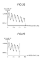
- FIGS. 26 to 28 are schematic diagrams for explaining the conventional technology 1.
- the horizontal axis in FIGS. 26 to 28 represents the frequency, and the vertical axis represents the volume of sound.
- a voice signal is a wide-band signal, for example, zero to six kilohertz.
- the wide-band signal is transmitted, if the band is limited from zero to four kilohertz, treble components from four to six kilohertz are lost.
- the transmitted voice signal is degraded to a narrow-band signal from zero to four kilohertz.
- the narrow-band signal is received as an input signal, an extension signal for compensating the lost signal is artificially created by using a signal from two to four kilohertz adjacent to the lost band. As depicted in FIG.
- the extension signal is then added to the narrow-band signal, so that the band from zero to four kilohertz is extended to the band from zero to six kilohertz, accordingly, the sound quality is improved.
- the signal expressed by a broken line indicates the extension signal.
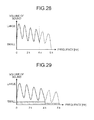
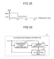
- FIGS. 29 to 32 are schematic diagrams for explaining the conventional technology 2. According to FIGS. 29 to 32 , explained below is a case where treble components from four to six kilohertz are lost, and an extension signal is created by using a signal in an adjacent band from two to four kilohertz.
- the horizontal axis in FIGS. 29 and 31 represents the frequency, and the vertical axis represents the volume of sound. Shadow parts in FIGS. 29 and 31 indicate the level of noises included in voice signals, and a signal expressed by a broken line indicates an extension signal.
- FIG. 29 to 32 are schematic diagrams for explaining the conventional technology 2. According to FIGS. 29 to 32 , explained below is a case where treble components from four to six kilohertz are lost, and an extension signal is created by using a signal in an adjacent band from two to four kilohertz.
- the horizontal axis in FIGS. 29 and 31 represents the frequency, and the vertical axis represents the volume of sound. Shadow parts in FIGS.
- FIG. 30 indicates the level of signal noise ratio (SNR) corresponding to FIG. 29
- FIG. 32 indicates the level of SNR corresponding to FIG. 31 .
- the SNR indicates a ratio of the level of voice to the level of noise, and the higher value of the SNR, the higher level of voice indicates.
- FIG. 33 is a schematic diagram for explaining an example of a configuration of the voice-band extending apparatus according to the conventional technology 2.
- a voice-band extending apparatus 10 includes an extension-signal creating unit 11, an SNR calculating unit 12, and a weight addition unit 13.
- the extension-signal creating unit 11 creates an extension signal by using a signal of an adjacent band among input signals that are input.
- the SNR calculating unit 12 calculates an SNR of the adjacent band.
- the weight addition unit 13 adds the extension signal to the input signal, and creates an output signal extended from the band of the input signal.
- the weight addition unit 13 attenuates the level of the whole of the extension signal such that a noise level included in the extension signal falls below a predetermined value, and then adds the extension signal to the input signal.
- the conventional technologies have a problem that when a lot of noises are included in an input signal, the sound quality cannot be surely improved even by extending the band.
- an extension signal when a lot of noises are included in an input signal, an extension signal also includes a lot of noises, consequently, the sound quality cannot be improved.
- the conventional technology 2 to suppress influence of noise, the level of the whole of an extension signal is attenuated, consequently, the level of a lost signal is not sufficiently compensated, and the sound quality cannot be improved.
- a voice-band extending apparatus includes an evaluating unit that evaluates one of a noise level and a signal noise ratio with respect to each of bands in an input signal that is input from an outside; a band selecting unit that selects a band that includes few noises from the input signal based on an evaluation result by the evaluating unit; a creating unit that creates an extension signal to extend a band in an input signal by using a signal of the band selected by the band selecting unit; and an addition unit that adds the extension signal created by the creating unit to the input signal.
- a voice-band extending method to be executed by a computer includes evaluating one of a noise level and a signal noise ratio with respect to each of bands in an input signal that is input from an outside; selecting a band that includes few noises from the input signal based on an evaluation result by processing of the evaluating of the noise level; creating an extension signal to extend a band in an input signal by using a signal of the band selected by processing of the selecting of a band; and adding the extension signal created by processing of the creating of the extension signal to the input signal.
- FIG. 1 is a schematic diagram that depicts a configuration of the voice-band extending apparatus according to the first embodiment.
- a voice-band extending apparatus 100 includes a fast Fourier transform (FFT) unit 110, a signal noise ratio (SNR) calculation processing unit 120, a band selecting unit 130, an extension-signal creating unit 140, an addition unit 150, and an inverse fast Fourier transform (IFFT) unit 160.
- FFT fast Fourier transform
- SNR signal noise ratio
- IFFT inverse fast Fourier transform
- the FFT unit 110 performs the Fourier transform on an input signal that is input from the outside, and outputs the Fourier-transformed input signal to the SNR calculation processing unit 120, the band selecting unit 130, and the addition unit 150.
- the input signal to be input into the FFT unit 110 is, for example, a narrow-band signal from zero to four kilohertz.
- the FFT unit 110 calculates a spectrum F 1n (j) with respect to each frame of the input signal based on Expression (1) described below.
- n denotes a frame number
- x n denotes an input signal in the n-th frame
- N denotes the length of FFT analysis
- j denotes the frequency BIN.
- frequency BIN 0 to 192 correspond to frequencies zero hertz to six hertz, respectively.
- the SNR calculation processing unit 120 calculates an SNR with respect to each of bands in an input signal, and outputs the calculated SNR of each band to the band selecting unit 130. In this case, assume that the SNR calculation processing unit 120 calculates each SNR by a bandwidth of two-kilohertz in the input signal. The SNR calculation processing unit 120 outputs the SNR of each band to the band selecting unit 130.
- the SNR calculation processing unit 120 is an example of an evaluating unit.
- the SNR calculated by the SNR calculation processing unit 120 is an example of a noise level or a signal noise ratio.
- FIG. 2 is a schematic diagram that depicts a configuration of the SNR calculation processing unit.
- the SNR calculation processing unit 120 includes a voice determining unit 121, a voice-level renewing unit 122, a noise-level renewing unit 123, and an SNR calculating unit 124.
- the voice determining unit 121 determines voice/non-voice with respect to each fame of an input signal. For example, similarly to a technology as disclosed in Japanese Patent No. 3849116 , the voice determining unit 121 calculates a feature amount by using a peak frequency and a pitch cycle of a power spectrum, and determines voice/non-voice based on whether the calculated feature amount is typical of voice.
- the voice determining unit 121 determines that the frame is voice. In contrast, when the feature amount of a frame of the input signal is not typical of voice, the voice determining unit 121 determines that the frame is non-voice. Assume that the voice determining unit 121 preliminarily stores a feature amount that is typical of voice.
- the voice determining unit 121 outputs the frame determined as voice to the voice-level renewing unit 122, and outputs the frame determined as non-voice to the noise-level renewing unit 123.
- the voice-level renewing unit 122 calculates a voice level with respect to each of bands in a frame, and outputs the calculated voice level to the SNR calculating unit 124.
- the voice-level renewing unit 122 calculates a voice level V(n, B 1 ) of each band by using Expression (2) described below.
- n denotes a frame number
- B i denotes the i-th band.
- spec_pow(n, B i ) denotes an average of spectrum power of the i-th band
- COF1 denotes a smoothing coefficient.
- V n ⁇ B i V ⁇ n - 1 , B i * COF ⁇ 1 + spec_pow n ⁇ B i * 1.0 - COF ⁇ 1
- the noise-level renewing unit 123 calculates a noise level with respect to each of bands in a frame, and outputs the calculated noise level to the SNR calculating unit 124.
- the noise-level renewing unit 123 calculates a noise level N(n, B i ) of each band by using Expression (3) described below.
- COF2 in Expression (3) denotes a smoothing coefficient.
- N n ⁇ B i N ⁇ n - 1 , B i * COF ⁇ 2 + spec_pow n ⁇ B i * 1.0 - COF ⁇ 2
- the band selecting unit 130 selects a band of which SNR exceeds a threshold and is the maximum SNR, based on respective SNRs of the bands.
- the band selecting unit 130 then outputs a signal of the selected band to the extension-signal creating unit 140.
- the threshold is an arbitrary value that is set not to select a band with a low SNR.
- the band selecting unit 130 is an example of a band selecting unit.
- FIG. 3 is a schematic diagram that depicts respective SNRs of bands.
- the SNR of a band 1 is zero decibel
- the SNR of a band 2 is zero decibel
- the SNR of a band 3 is six decibels.
- the band 1 is from zero to two kilohertz
- the band 2 is from one to three kilohertz
- the band 3 is from two to four kilohertz.
- the frequency BIN range of the band 1 is from 0 to 63
- the frequency BIN range of the band 2 is from 32 to 95
- the frequency BIN range of the band 3 is from 64 to 127.
- the band selecting unit 130 selects the band 3, and outputs a signal of the band 3 to the extension-signal creating unit 140.
- the band selecting unit 130 outputs a signal of a level zero to the extension-signal creating unit 140.
- the threshold is not limited by this exemplification, and can be set to an arbitrary value by a user who uses the voice-band extending apparatus 100.
- the extension-signal creating unit 140 creates an extension signal based on a signal acquired from the band selecting unit 130.
- the extension signal is a signal that compensates a treble component of the input signal.
- the extension-signal creating unit 140 outputs the created extension signal to the addition unit 150.
- the extension-signal creating unit 140 is an example of a creating unit.
- the extension-signal creating unit 140 creates an attenuation signal by applying a gain to a signal acquired from the band selecting unit 130, and creates an extension signal by sifting the attenuation signal to an arbitrary frequency.
- a signal acquired from the band selecting unit 130 is referred to as a selection signal, and a gain to be applied to the selection signal is referred to as an application gain.
- the extension-signal creating unit 140 obtains an extension signal in accordance with Expression (5) described below.
- Expression (5) j denotes a frequency BIN, and shift denotes a frequency shift amount.
- F ex (j) denotes a spectrum of an extension signal corresponding to a frequency BIN "j”
- F in (j) denotes a spectrum of a selection signal corresponding to the frequency BIN "j”.
- F ex ⁇ j + shift gain j * F in j
- FIG. 4 is a schematic diagram that depicts relation between frequency BIN and magnitude of application gain. As depicted in FIG. 4 , as the frequency BIN is getting larger, the magnitude of the application gain is getting smaller. According to the example depicted in FIG. 4 , when the frequency BIN changes from 64 to 128, the magnitude of the application gain changes from 0 decibel to -9 decibels. In this way, by using a value with which relation between frequency and application gain goes downward rightwardly, an extension signal that typically represents characteristics of voice can be created. The reason for this is because a voice signal has a characteristic that the higher treble, the smaller the voice level is.
- FIG. 5 is a schematic diagram (1) for explaining extension-signal creating processing executed by the extension-signal creating unit.
- the horizontal axis in FIG. 5 represents the frequency and the frequency BIN, and the vertical axis represents the volume of sound.
- the horizontal axis in FIG. 5 represents the frequency and the frequency BIN
- the vertical axis represents the volume of sound.
- the extension-signal creating unit 140 attenuates the selection signal 5a by applying an application gain to the selection signal 5a, thereby creating an attenuation signal 5b.
- the extension-signal creating unit 140 then shifts the attenuation signal 5b by two kilohertz to the treble side, thereby creating the extension signal 5c.
- the present invention is not limited to this.
- the value of the application gain gain(j) can be changed in accordance with a band selected by the band selecting unit 130. For example, when a band selected by the band selecting unit 130 is from zero to two kilohertz, the value of the application gain gain(j) can be smaller to attenuate to a larger extent.
- the extension-signal creating unit 140 increases or decreases the level of the extension signal, and eliminates discontinuity of spectra at the border frequency, thereby avoiding degrading the sound quality.
- - ⁇ F ex (128)-F in (127) ⁇ (128+L-j)/L expresses an adjustment gain for adjusting the extension signal.
- L corresponds to the frequency BIN range in which a level adjustment is performed.
- FIG. 6 is a schematic diagram that depicts relation between frequency BIN and adjustment gain.
- the horizontal axis in FIG. 6 represents the frequency and the frequency BIN, and the vertical axis represents the magnitude of the adjustment gain.
- FIG. 7 is a schematic diagram for explaining level adjustment processing executed by the extension-signal creating unit.
- the horizontal axis in FIG. 7 represents the frequency and the frequency BIN, and the vertical axis represents the volume of sound.
- a signal 7a in FIG. 7 denotes an input signal
- a signal 7b denotes an extension signal
- a signal 7c denotes an extension signal after level adjustment.
- the extension-signal creating unit 140 applies the adjustment gain, and adjusts the extension signal 7b to the extension signal 7c, so that spectra of the input signal 7a and the extension signal 7c become continuous, thereby avoiding sound-quality degradation.
- the addition unit 150 adds an extension signal to an input signal, and creates a band-extended signal.
- the band-extended signal created by the addition unit 150 is, for example, a signal from zero to six kilohertz.
- the addition unit 150 outputs the created band-extended signal to the IFFT unit 160.
- the addition unit 150 is an example of an addition unit.
- the addition unit 150 adds the extension signal to the input signal by using Expression (7) described below.
- F out (j) in FIG. 7 denotes a spectrum of the band-extended signal
- F in (j) denotes a spectrum of the input signal
- F ex (j) denotes a spectrum of the extension signal.
- F out j F in j + F ex j
- the IFFT unit 160 performs the inverse fast Fourier transform on a band-extended signal, and creates an output signal. For example, the IFFT unit 160 creates an output signal x n by using Expression (8) described below. The IFFT unit 160 outputs the created output signal to the outside.
- FIG. 8 is a flowchart that depicts the process procedure performed by the voice-band extending apparatus according to the first embodiment. The processing depicted in FIG. 8 is to be executed, for example, upon receiving input of an input signal into the voice-band extending apparatus 100.
- Step S101 when an input signal is input into the voice-band extending apparatus 100 (Step S101); the voice-band extending apparatus 100 performs the Fourier transform on the input signal (Step S102). The voice-band extending apparatus 100 calculates an SNR with respect to each of bands in the input signal (Step S103).
- the voice-band extending apparatus 100 selects a band of which SNR exceeds the threshold and is the maximum SNR, based on respective SNRs of the bands (Step S104).
- the voice-band extending apparatus 100 creates an extension signal based on a signal of the selected band (Step S105); adds the created extension signal to the input signal, thereby creating a band-extended signal (Step S106).
- the voice-band extending apparatus 100 performs the inverse Fourier transform on the band-extended signal (Step S107) ; and outputs the inverse-Fourier-transformed band-extended signal as an output signal (Step S108).
- the voice-band extending apparatus 100 calculates an SNR with respect to each of bands in an input signal that is input, and selects a band of which SNR exceeds a threshold and is the maximum SNR based on respective SNRs of the bands.
- the voice-band extending apparatus 100 creates an extension signal by using a signal of the selected band, thereby extending the input signal.
- the voice-band extending apparatus 100 creates and extension signal by using a signal of a band with few noises in the input signal, thereby suppressing noises included in the extension signal to a low level, so that the sound quality can be improved.
- the voice-band extending apparatus 100 changes an application gain in accordance with the frequency of a selected band even if selecting any of the bands in the input signal, thereby being capable to create an extension signal that is appropriately attenuated so as to represent characteristics of voice typically, so that the sound quality can be improved.
- FIGS. 9 and 10 are schematic diagrams for explaining effects of the voice-band extending apparatus according to the first embodiment.
- the horizontal axis in FIG. 9 represents the frequency, and the vertical axis represents the volume of sound.
- a shadow part in FIG. 9 indicates the level of noises included in a voice signal.
- FIG. 10 depicts the level of SNR corresponding to FIG. 9 .
- SNR SNR
- the voice-band extending apparatus 100 selects the band from zero to two kilohertz as a band of which SNR exceeds the threshold and is the maximum SNR.
- the voice-band extending apparatus 100 creates an extension signal from four to six kilohertz by using a signal of the selected band, and extends the input signal, thereby achieving an effect of great improvement in the sound quality while suppressing influence of noise.
- the voice-band extending apparatus 100 adds a signal of the level 0 instead of an extension signal to the input signal. For this reason, the voice-band extending apparatus 100 is configured not to add an extension signal created based on a signal of which SNR is lower than the threshold, thereby being capable to avoid degradation of the sound quality.
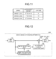
- FIG. 11 is a schematic diagram (2) that depicts respective SNRs of bands.
- the SNR of the band 1 is zero decibel
- the SNR of the band 2 is 10 decibels
- the SNR of the band 3 is six decibels.
- the band 1 is from zero to two kilohertz
- the band 2 is from one to three kilohertz
- the band 3 is from two to four kilohertz.
- the band selecting unit 130 selects the band 2.
- the threshold is not limited by this exemplification, and can be set to an arbitrary value by a user who uses the voice-band extending apparatus 100.
- FIG. 12 is a schematic diagram that depicts a configuration of the voice-band extending apparatus according to the second embodiment.
- a voice-band extending apparatus 200 includes the FFT unit 110, the SNR calculation processing unit 120, a band selecting unit 230, the extension-signal creating unit 140, the addition unit 150, and the IFFT unit 160.
- explanations of the FFT unit 110 and the SNR calculation processing unit 120 depicted in FIG. 10 are similar to explanations of the FFT unit 110 and the SNR calculation processing unit 120 depicted in FIG. 1 .
- extension-signal creating unit 140 the addition unit 150, and the IFFT unit 160 depicted in 12 are similar to explanations of the extension-signal creating unit 140, the addition unit 150, and the IFFT unit 160 depicted in FIG. 1 .
- the band selecting unit 230 selects a band that has an SNR exceeding a threshold and is closest to a band to be extended, based on respective SNRs of bands. The band selecting unit 230 then outputs a signal of the selected band to the extension-signal creating unit 140.
- the threshold is an arbitrary value that is set not to select a band with a low SNR.
- the band selecting unit 230 is an example of the band selecting unit.
- FIG. 13 is a schematic diagram (3) that depicts respective SNRs of bands.
- the SNR of the band 1 is zero decibel
- the SNR of the band 2 is 10 decibels
- the SNR of the band 3 is six decibels.
- the band 1 is from zero to two kilohertz
- the band 2 is from one to three kilohertz
- the band 3 is from two to four kilohertz.
- the band selecting unit 230 selects the band 3, and outputs a signal of the band 3 to the extension-signal creating unit 140.
- the band selecting unit 230 outputs a signal of the level zero to the extension-signal creating unit 140.
- the threshold is not limited by this exemplification, and can be set to an arbitrary value by a user who uses the voice-band extending apparatus 200.
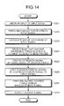
- FIG. 14 is a flowchart that depicts a process procedure performed by the voice-band extending apparatus according to the second embodiment. The processing depicted in FIG. 14 is to be executed, for example, upon receiving input of an input signal into the voice-band extending apparatus 200.
- Step S201 when an input signal is input into the voice-band extending apparatus 200 (Step S201); the voice-band extending apparatus 200 performs the Fourier transform on the input signal (Step S202). The voice-band extending apparatus 200 calculates an SNR with respect to each of bands in the input signal (Step S203).
- the voice-band extending apparatus 200 selects a band that has an SNR exceeding a threshold and is closest to a band to be extended, based on respective SNRs of the bands (Step S204).
- the voice-band extending apparatus 200 creates an extension signal by using a signal of the selected band (Step S205); and adds the created extension signal to the input signal, thereby creating a band-extended signal (Step S206).
- the voice-band extending apparatus 200 performs the inverse Fourier transform on the band-extended signal (Step S207); and outputs the inverse-Fourier-transformed band-extended signal as an output signal (Step S208).
- the voice-band extending apparatus 200 calculates an SNR with respect to each of bands in an input signal that is input, and selects a band that has an SNR exceeding a threshold and has a waveform closest to the waveform of a band to be extended, based on respective SNRs of the bands.
- the voice-band extending apparatus 200 creates an extension signal by using a signal of the selected band, thereby extending the input signal.
- the voice-band extending apparatus 200 creates an extension signal by using a signal that has few noises and is close to the signal waveform of a band to be extended in the input signal, thereby being capable to create an extension signal closer to a treble signal waveform, so that the sound quality can be improved.
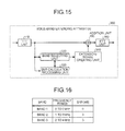
- FIG. 15 is a schematic diagram that depicts a configuration of the voice-band extending apparatus according to the third embodiment.
- a voice-band extending apparatus 300 includes the FFT unit 110, an SNR calculation processing unit 320, a band selecting unit 330, an extension-signal creating unit 340, the addition unit 150, and the IFFT unit 160.
- explanations of the FFT unit 110, the addition unit 150, and the IFFT unit 160 depicted in FIG. 15 are similar to explanations of the FFT unit 110, the addition unit 150, and the IFFT unit 160 depicted in FIG. 1 .
- the SNR calculation processing unit 320 has the same function as that of the SNR calculation processing unit 120. Furthermore, the SNR calculation processing unit 320 receives a command to recalculate SNRs by a bandwidth set by the band selecting unit 330 described later. The SNR calculation processing unit 320 then recalculates SNRs based on the command received from the band selecting unit 330, and outputs the recalculated SNRs of the respective bands to the band selecting unit 330.
- the SNR calculation processing unit 320 is an example of the evaluating unit.
- the SNR calculation processing unit 320 receives from the band selecting unit 330 a command to recalculate SNRs by a bandwidth of one kilohertz. The SNR calculation processing unit 320 then recalculates SNRs by a bandwidth of one kilohertz, and outputs the recalculated SNRs of the respective bands to the band selecting unit 330.
- the band selecting unit 330 has the same function as that of the band selecting unit 130. Furthermore, when the input signal includes no band of which SNR exceeds the threshold, the band selecting unit 330 sets a bandwidth for calculating each SNR to a narrower bandwidth. The band selecting unit 330 outputs a command to recalculate SNRs by the set bandwidth to the SNR calculation processing unit 320. The band selecting unit 330 then selects a band of which SNR exceeds a threshold and is the maximum SNR, based on the recalculated SNRs, and outputs a signal of the selected band to the extension-signal creating unit 340.
- the threshold is an arbitrary value that is set not to select a band with a low SNR. Moreover, the band selecting unit 330 is an example of the band selecting unit.
- FIG. 16 is a schematic diagram (4) that depicts respective SNRs of bands.
- each SNR is calculated by a bandwidth of two kilohertz is explained below.
- the SNR of the band 1 is zero decibel
- the SNR of the band 2 is three decibels
- the SNR of the band 3 is three decibels.
- the band 1 is from zero to two kilohertz
- the band 2 is from one to three kilohertz
- the band 3 is from two to four kilohertz.
- the band selecting unit 330 sets a bandwidth for calculating each SNR to one kilohertz, and outputs to the SNR calculation processing unit 320 a command to recalculate SNRs by the bandwidth of one kilohertz.
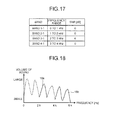
- FIG. 17 is a schematic diagram (5) that depicts respective SNRs of bands.
- each SNR is calculated by a bandwidth of one kilohertz.
- the SNR of the band 1-1 is zero decibel
- the SNR of the band 2-1 is 0 decibel
- the SNR of the band 3-1 is six decibels
- the SNR of the band 4-1 is zero decibel.
- the band 1-1 is from zero to one kilohertz
- the band 2-1 is from one to two kilohertz
- the band 3-1 is from two to three kilohertz
- the band 4-1 is from three to four kilohertz.
- the band selecting unit 330 selects the band 3-1, and outputs a signal of the band 3-1 to the extension-signal creating unit 340.
- the threshold is not limited by this exemplification, and can be set to an arbitrary value by a user who uses the voice-band extending apparatus 300.
- the extension-signal creating unit 340 has the same function as that of the extension-signal creating unit 140. Furthermore, when a band acquired from the band selecting unit 330 is narrower than a band to be extended, the extension-signal creating unit 340 creates a plurality of attenuation signals from a signal of the acquired band, and shifts the attenuation signals to respective different frequencies, thereby creating an extension signal.
- the extension-signal creating unit 340 is and example of the creating unit.
- FIG. 18 is a schematic diagram (2) for explaining extension-signal creating processing executed by the extension-signal creating unit.
- the horizontal axis in FIG. 18 represents the frequency, and the vertical axis represents the volume of sound.
- the horizontal axis in FIG. 18 represents the frequency
- the vertical axis represents the volume of sound.
- explained below is a case of creating an extension signal 18b from four to six kilohertz from a selection signal 18a from two to three kilohertz selected by the band selecting unit 330.
- the extension-signal creating unit 340 attenuates the selection signal 18a by applying an application gain to the selection signal 18a, and shifts it by two kilohertz to the treble side, thereby creating a signal from four to five kilohertz. Moreover, the extension-signal creating unit 340 attenuates the selection signal 18a by applying the application gain to the selection signal 18a, and shifts it by three kilohertz to the treble side, thereby creating a signal from five to six kilohertz. The extension-signal creating unit 340 then adds the signal from four to five kilohertz to the signal from five to six kilohertz, thereby creating the extension signal 18b from four to six kilohertz.
- FIG. 19 is a flowchart that depicts a process procedure performed by the voice-band extending apparatus according to the third embodiment. The processing depicted in FIG. 19 is to be executed, for example, upon receiving input of an input signal into the voice-band extending apparatus 300 .
- Step S301 when an input signal is input into the voice-band extending apparatus 300 (Step S301); the voice-band extending apparatus 300 performs the Fourier transform on the input signal (Step S302) .
- the voice-band extending apparatus 300 calculates an SNR with respect to each of bands in the input signal (Step S303).
- Step S304 If there is any band of which SNR exceeds the threshold (Yes at Step S304), the voice-band extending apparatus 300 selects a band that has the maximum SNR (Step S305). By contrast, if there is no band of which SNR exceeds the threshold (No at Step S304), the voice-band extending apparatus 300 narrows the bandwidth for calculating each SNR, and recalculates SNRs by the narrowed bandwidth (Step S306), and goes to Step S305.
- the voice-band extending apparatus 300 creates an extension signal from a signal of the selected band (Step S307); and adds the created extension signal to the input signal, thereby creating a band-extended signal (Step S308).
- the voice-band extending apparatus 300 performs the inverse Fourier transform on the band-extended signal (Step S309); and outputs the inverse-Fourier-transformed band-extended signal as an output signal (Step S310).
- the voice-band extending apparatus 300 calculates an SNR with respect to each of bands in an input signal that is input, and selects a band of which SNR exceeds a threshold and is the maximum SNR, based on respective SNRs of the bands. Moreover, if there is no band of which SNR exceeds the threshold, the voice-band extending apparatus 300 narrows the bandwidth for calculating each SNR, recalculates SNRs by the narrowed bandwidth, thereby selecting a band based on the respective recalculated SNRs of the bands.
- the voice-band extending apparatus 300 detects a band with few noises and creates an extension signal by adjusting the bandwidth, so that the sound quality can be improved.
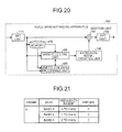
- FIG. 20 is a schematic diagram that depicts a configuration of the voice-band extending apparatus according to the fourth embodiment.
- a voice-band extending apparatus 400 includes the FFT unit 110, an SNR calculation processing unit 420, a band selecting unit 430, the extension-signal creating unit 140, the addition unit 150, the IFFT unit 160, and a memory 470.
- explanations of the FFT unit 110, the extension-signal creating unit 140, the addition unit 150, and the IFFT unit 160 depicted in FIG. 20 are similar to explanations of the FFT unit 110, the extension-signal creating unit 140, the addition unit 150, and the IFFT unit 160 depicted in FIG. 1 .
- the SNR calculation processing unit 420 has the same function as that of the SNR calculation processing unit 120. Furthermore, the SNR calculation processing unit 420 acquires a frame in the past of an input signal from the memory 470 described later, and recalculates respective SNRs of bands by using the past frame.
- the SNR calculation processing unit 420 is an example of the evaluating unit.
- the SNR calculation processing unit 420 acquires the (n-1)th frame from the memory 470, and calculates respective SNRs of bands by using the (n-1)th frame. The SNR calculation processing unit 420 then outputs the respective SNRs of the bands in the (n-1)th frame to the band selecting unit 430.
- the band selecting unit 430 has the same function as that of the band selecting unit 130. Furthermore, when the input signal includes no band of which SNR exceeds the threshold, the band selecting unit 430 outputs to the SNR calculation processing unit 420 a command to recalculate respective SNRs of the bands by using a past frame of the input signal. The band selecting unit 430 selects a band that has an SNR exceeding a threshold and is of a frame closest to the current frame, based on the SNRs recalculated by the SNR calculation processing unit 420. The band selecting unit 430 then outputs a signal of the selected band to the extension-signal creating unit 140.
- the threshold is an arbitrary value that is set not to select a band with a low SNR.
- the band selecting unit 430 is an example of the band selecting unit.
- FIG. 21 is a schematic diagram (6) that depicts respective SNRs of the bands.
- the SNR of the band 1 in the n-th frame is zero decibel
- the SNR of the band 2 is zero decibel
- the SNR of the band 3 is zero decibel.
- the band 1 is from zero to two kilohertz
- the band 2 is from one to three kilohertz
- the band 3 is from two to four kilohertz.
- the n-th frame is the current frame.
- the band selecting unit 430 outputs to the SNR calculation processing unit 420 a command to recalculate SNRs by using the (n-1)th frame and the (n-2)th frame of the input signal.
- the band selecting unit 430 acquires respective SNRs of the bands recalculated by the SNR calculation processing unit 420.
- FIG. 22 is a schematic diagram (7) that depicts respective SNRs of the bands.
- the SNR of the band 1 in the (n-1)th frame is zero decibel
- the SNR of the band 2 is zero decibel
- the SNR of the band 3 is six decibels.
- the SNR of the band 1 in the (n-2)th frame is zero decibel
- the SNR of the band 2 is zero decibel
- the SNR of the band 3 is six decibels.
- the band 1 is from zero to two kilohertz
- the band 2 is from one to three kilohertz
- the band 3 is from two to four kilohertz.
- the (n-1) th frame is at one frame previous to the current frame
- the (n-2)th frame is at two frames previous to the current frame.
- a band of which SNR exceeds the threshold "five" is the band 3 in the (n-1) th frame, and the band 3 in the (n-2)th frame.
- a band of a frame closest to the current frame is the band 3 in the (n-1)th frame.
- the band selecting unit 430 selects the band 3 in the (n-1) th frame, and outputs a signal of the band 3 in the (n-1) th frame to the extension-signal creating unit 140.
- the threshold is not limited by this exemplification, and can be set to an arbitrary value by a user who uses the voice-band extending apparatus 400.
- the past frames used by the band selecting unit 430 are not limited to the (n-1) th frame and the (n-2) th frame, and a further previous frame can be used within a range in which the waveform of a voice signal does not change to a large extent. For example, assuming that one frame is equivalent to 256 samples, the waveform of a voice signal does not change substantially within approximately eight frames, therefore, the band selecting unit 430 can use frames up to the (n-7)th frame.
- the memory 470 stores an input signal output from the FFT unit 110 with respect to each frame. For example, the memory 470 stores the n-th frame, the (n-1) th frame, and the (n-2)th frame of the input signal.
- FIG. 23 is a flowchart that depicts the process procedure performed by the voice-band extending apparatus according to the fourth embodiment. The processing depicted in FIG. 23 is to be executed, for example, upon receiving input of an input signal into the voice-band extending apparatus 400 .
- Step S401 when an input signal is input into the voice-band extending apparatus 400 (Step S401) ; the voice-band extending apparatus 400 performs the Fourier transform on the input signal (Step S402). The voice-band extending apparatus 400 calculates an SNR with respect to each of bands in the input signal (Step S403).
- Step S404 If there is any band of which SNR exceeds the threshold (Yes at Step S404), the voice-band extending apparatus 400 selects a band that has the maximum SNR (Step S405). By contrast, if there is no band of which SNR exceeds the threshold (No at Step S404), the voice-band extending apparatus 400 recalculates respective SNRs of the bands by using a past frame of the input signal (Step S406), and goes to Step S405.
- the voice-band extending apparatus 400 creates an extension signal from a signal of the selected band (Step S407); and adds the created extension signal to the input signal, thereby creating a band-extended signal (Step S408).
- the voice-band extending apparatus 400 performs the inverse Fourier transform on the band-extended signal (Step S409); and outputs the inverse-Fourier-transformed band-extended signal as an output signal (Step S410).
- the voice-band extending apparatus 400 calculates an SNR with respect to each of bands in an input signal that is input, and selects a band of which SNR exceeds a threshold and is the maximum SNR, based on respective SNRs of the bands. Moreover, if there is no band of which SNR exceeds the threshold, the voice-band extending apparatus 400 recalculates respective SNRs of the bands by using a past frame of the input signal, thereby selecting a band based on the respective recalculated SNRs of the bands.
- the voice-band extending apparatus 400 selects a band with few noises from a past input signal and creates an extension signal, thereby suppressing noises included in the extension signal to a low level, so that the sound quality can be improved.
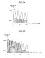
- FIGS. 24 and 25 are schematic diagrams for explaining effects of the voice-band extending apparatus according to the fourth embodiment.
- the horizontal axis in FIGS. 24 to 25 represents the frequency, and the vertical axis represents the volume of sound. Shadow parts in FIGS. 24 and 35 indicate the level of noises included in voice signals.
- FIG. 24 depicts a current frame of the input signal
- FIG. 25 depicts a past frame of the input signal.
- SNR of a band from zero to four kilohertz depicted in FIG. 24 does not exceed the threshold
- the SNR of a band from two to four kilohertz depicted in FIG. 25 exceeds the threshold and is the maximum SNR.
- the voice-band extending apparatus 400 selects the band from two to four kilohertz in the past frame as a band of which SNR exceeds the threshold and is the maximum SNR.
- the voice-band extending apparatus 400 creates an extension signal from four to six kilohertz by using a signal of the selected band, and extends the input signal, thereby achieving an effect of great improvement in the sound quality while suppressing influence of noise.
- all or part of the processing configured to be automatically performed can be manually performed, or all or part of the processing configured to be manually performed can be automatically performed.
- process procedures, the control procedures, the specific names, and information including various data and parameters described in the above description or depicted in the drawings can be arbitrarily changed unless otherwise specified.
- the components of the voice-band extending apparatuses 100, 200, 300, and 400 depicted in FIGS. 1 , 12 , 15 , and 20 are conceptual for describing functions, and not necessarily to be physically configured as depicted in the drawings.
- concrete forms of distribution and integration the voice-band extending apparatuses 100, 200, 300, and 400 are not limited to those depicted in the drawings, and all or part of the apparatus can be configured to be functionally or physically distributed and integrated in an arbitrary unit depending on various loads and conditions in use.
- a signal unit can have the functions of the SNR calculation processing unit 120 and the band selecting unit 130.
- Respective processing functions performed by the FFT unit 110, the SNR calculation processing units 120, 320, and 420, the band selecting units 130, 230, 330, and 430, the extension-signal creating units 140 and 340, the addition unit 150, and the IFFT unit 160 are to be implemented as follows. Precisely, all or an arbitrary part of these processing functions can be implemented by a central processing unit (CPU) and a computer program to be analyzed and executed by the CPU, or can be implemented as hardware by wired logic.
- CPU central processing unit
- the memory 470 corresponds to a semiconductor memory device, for example, a random access memory (RAM), a read-only memory (ROM), or a flash memory, or a storage device, such as a hard disk, or an optical disk.
- RAM random access memory
- ROM read-only memory
- flash memory or a storage device, such as a hard disk, or an optical disk.
- the sound quality can be improved.
Landscapes
- Engineering & Computer Science (AREA)
- Computational Linguistics (AREA)
- Quality & Reliability (AREA)
- Signal Processing (AREA)
- Health & Medical Sciences (AREA)
- Audiology, Speech & Language Pathology (AREA)
- Human Computer Interaction (AREA)
- Physics & Mathematics (AREA)
- Acoustics & Sound (AREA)
- Multimedia (AREA)
- Telephone Function (AREA)
- Circuits Of Receivers In General (AREA)
Applications Claiming Priority (1)
| Application Number | Priority Date | Filing Date | Title |
|---|---|---|---|
| JP2010216035A JP5552988B2 (ja) | 2010-09-27 | 2010-09-27 | 音声帯域拡張装置および音声帯域拡張方法 |
Publications (2)
| Publication Number | Publication Date |
|---|---|
| EP2434486A2 true EP2434486A2 (de) | 2012-03-28 |
| EP2434486A3 EP2434486A3 (de) | 2013-12-11 |
Family
ID=44508740
Family Applications (1)
| Application Number | Title | Priority Date | Filing Date |
|---|---|---|---|
| EP11171463.0A Withdrawn EP2434486A3 (de) | 2010-09-27 | 2011-06-27 | Sprachbanderweiterungsvorrichtung und Sprachbanderweiterungsverfahren |
Country Status (4)
| Country | Link |
|---|---|
| US (1) | US20120078632A1 (de) |
| EP (1) | EP2434486A3 (de) |
| JP (1) | JP5552988B2 (de) |
| CN (1) | CN102419980B (de) |
Families Citing this family (1)
| Publication number | Priority date | Publication date | Assignee | Title |
|---|---|---|---|---|
| JP6282925B2 (ja) * | 2014-05-13 | 2018-02-21 | 日本電信電話株式会社 | 音声強調装置、音声強調方法及びプログラム |
Citations (3)
| Publication number | Priority date | Publication date | Assignee | Title |
|---|---|---|---|---|
| JPH08130494A (ja) | 1994-10-28 | 1996-05-21 | Fujitsu Ltd | 音声信号処理システム |
| JP3849116B2 (ja) | 2001-02-28 | 2006-11-22 | 富士通株式会社 | 音声検出装置及び音声検出プログラム |
| JP2008176328A (ja) | 2007-01-18 | 2008-07-31 | Harman Becker Automotive Systems Gmbh | 拡張帯域幅を有する音響信号を提供する方法および装置 |
Family Cites Families (35)
| Publication number | Priority date | Publication date | Assignee | Title |
|---|---|---|---|---|
| US5469494A (en) * | 1994-03-02 | 1995-11-21 | Telular International, Inc. | Self-diagnostic system for cellular-transceiver systems |
| US5715365A (en) * | 1994-04-04 | 1998-02-03 | Digital Voice Systems, Inc. | Estimation of excitation parameters |
| US5806025A (en) * | 1996-08-07 | 1998-09-08 | U S West, Inc. | Method and system for adaptive filtering of speech signals using signal-to-noise ratio to choose subband filter bank |
| SE512719C2 (sv) * | 1997-06-10 | 2000-05-02 | Lars Gustaf Liljeryd | En metod och anordning för reduktion av dataflöde baserad på harmonisk bandbreddsexpansion |
| US6035048A (en) * | 1997-06-18 | 2000-03-07 | Lucent Technologies Inc. | Method and apparatus for reducing noise in speech and audio signals |
| DE19743662A1 (de) * | 1997-10-02 | 1999-04-08 | Bosch Gmbh Robert | Verfahren und Vorrichtung zur Erzeugung eines bitratenskalierbaren Audio-Datenstroms |
| TW376611B (en) * | 1998-05-26 | 1999-12-11 | Koninkl Philips Electronics Nv | Transmission system with improved speech encoder |
| DE10026872A1 (de) * | 2000-04-28 | 2001-10-31 | Deutsche Telekom Ag | Verfahren zur Berechnung einer Sprachaktivitätsentscheidung (Voice Activity Detector) |
| US6615169B1 (en) * | 2000-10-18 | 2003-09-02 | Nokia Corporation | High frequency enhancement layer coding in wideband speech codec |
| DE60304479T2 (de) * | 2002-08-01 | 2006-12-14 | Matsushita Electric Industrial Co., Ltd., Kadoma | Audiodekodierungsvorrichtung und audiodekodierungsverfahren auf der basis der spektralband duplikation |
| US7333930B2 (en) * | 2003-03-14 | 2008-02-19 | Agere Systems Inc. | Tonal analysis for perceptual audio coding using a compressed spectral representation |
| EP3118849B1 (de) * | 2004-05-19 | 2020-01-01 | Fraunhofer Gesellschaft zur Förderung der Angewand | Codierungsvorrichtung, decodierungsvorrichtung und verfahren dafür |
| PL1810281T3 (pl) * | 2004-11-02 | 2020-07-27 | Koninklijke Philips N.V. | Kodowanie i dekodowanie sygnałów audio z wykorzystaniem banków filtrów o wartościach zespolonych |
| US8249861B2 (en) * | 2005-04-20 | 2012-08-21 | Qnx Software Systems Limited | High frequency compression integration |
| US8311840B2 (en) * | 2005-06-28 | 2012-11-13 | Qnx Software Systems Limited | Frequency extension of harmonic signals |
| EP1943643B1 (de) * | 2005-11-04 | 2019-10-09 | Nokia Technologies Oy | Audio-komprimierung |
| JP5055759B2 (ja) * | 2005-12-16 | 2012-10-24 | 沖電気工業株式会社 | 帯域変換信号生成器及び帯域拡張装置 |
| EP1979901B1 (de) * | 2006-01-31 | 2015-10-14 | Unify GmbH & Co. KG | Verfahren und anordnungen zur audiosignalkodierung |
| GB2437559B (en) * | 2006-04-26 | 2010-12-22 | Zarlink Semiconductor Inc | Low complexity noise reduction method |
| KR101291672B1 (ko) * | 2007-03-07 | 2013-08-01 | 삼성전자주식회사 | 노이즈 신호 부호화 및 복호화 장치 및 방법 |
| KR101355376B1 (ko) * | 2007-04-30 | 2014-01-23 | 삼성전자주식회사 | 고주파수 영역 부호화 및 복호화 방법 및 장치 |
| KR101411901B1 (ko) * | 2007-06-12 | 2014-06-26 | 삼성전자주식회사 | 오디오 신호의 부호화/복호화 방법 및 장치 |
| US8433582B2 (en) * | 2008-02-01 | 2013-04-30 | Motorola Mobility Llc | Method and apparatus for estimating high-band energy in a bandwidth extension system |
| US20090201983A1 (en) * | 2008-02-07 | 2009-08-13 | Motorola, Inc. | Method and apparatus for estimating high-band energy in a bandwidth extension system |
| US8036891B2 (en) * | 2008-06-26 | 2011-10-11 | California State University, Fresno | Methods of identification using voice sound analysis |
| US8532998B2 (en) * | 2008-09-06 | 2013-09-10 | Huawei Technologies Co., Ltd. | Selective bandwidth extension for encoding/decoding audio/speech signal |
| JP4783412B2 (ja) * | 2008-09-09 | 2011-09-28 | 日本電信電話株式会社 | 信号広帯域化装置、信号広帯域化方法、そのプログラム、その記録媒体 |
| US9947340B2 (en) * | 2008-12-10 | 2018-04-17 | Skype | Regeneration of wideband speech |
| GB0822537D0 (en) * | 2008-12-10 | 2009-01-14 | Skype Ltd | Regeneration of wideband speech |
| GB2466668A (en) * | 2009-01-06 | 2010-07-07 | Skype Ltd | Speech filtering |
| US8463599B2 (en) * | 2009-02-04 | 2013-06-11 | Motorola Mobility Llc | Bandwidth extension method and apparatus for a modified discrete cosine transform audio coder |
| US8280725B2 (en) * | 2009-05-28 | 2012-10-02 | Cambridge Silicon Radio Limited | Pitch or periodicity estimation |
| US8515768B2 (en) * | 2009-08-31 | 2013-08-20 | Apple Inc. | Enhanced audio decoder |
| US8321215B2 (en) * | 2009-11-23 | 2012-11-27 | Cambridge Silicon Radio Limited | Method and apparatus for improving intelligibility of audible speech represented by a speech signal |
| CN102652336B (zh) * | 2009-12-28 | 2015-02-18 | 三菱电机株式会社 | 声音信号复原装置以及声音信号复原方法 |
-
2010
- 2010-09-27 JP JP2010216035A patent/JP5552988B2/ja not_active Expired - Fee Related
-
2011
- 2011-06-13 US US13/158,812 patent/US20120078632A1/en not_active Abandoned
- 2011-06-27 EP EP11171463.0A patent/EP2434486A3/de not_active Withdrawn
- 2011-06-29 CN CN201110179765.2A patent/CN102419980B/zh not_active Expired - Fee Related
Patent Citations (3)
| Publication number | Priority date | Publication date | Assignee | Title |
|---|---|---|---|---|
| JPH08130494A (ja) | 1994-10-28 | 1996-05-21 | Fujitsu Ltd | 音声信号処理システム |
| JP3849116B2 (ja) | 2001-02-28 | 2006-11-22 | 富士通株式会社 | 音声検出装置及び音声検出プログラム |
| JP2008176328A (ja) | 2007-01-18 | 2008-07-31 | Harman Becker Automotive Systems Gmbh | 拡張帯域幅を有する音響信号を提供する方法および装置 |
Also Published As
| Publication number | Publication date |
|---|---|
| JP2012073295A (ja) | 2012-04-12 |
| JP5552988B2 (ja) | 2014-07-16 |
| EP2434486A3 (de) | 2013-12-11 |
| US20120078632A1 (en) | 2012-03-29 |
| CN102419980A (zh) | 2012-04-18 |
| CN102419980B (zh) | 2014-04-16 |
Similar Documents
| Publication | Publication Date | Title |
|---|---|---|
| JP7177185B2 (ja) | 信号分類方法および信号分類デバイス、ならびに符号化/復号化方法および符号化/復号化デバイス | |
| US8412520B2 (en) | Noise reduction device and noise reduction method | |
| US8027743B1 (en) | Adaptive noise reduction | |
| US7912729B2 (en) | High-frequency bandwidth extension in the time domain | |
| RU2471253C2 (ru) | Способ и устройство для оценивания энергии полосы высоких частот в системе расширения полосы частот | |
| EP3149730B1 (de) | Verbesserung der verständlichkeit von sprachinhalten in einem audiosignal | |
| US8989403B2 (en) | Noise suppression device | |
| US7873114B2 (en) | Method and apparatus for quickly detecting a presence of abrupt noise and updating a noise estimate | |
| CN104067339B (zh) | 噪音抑制装置 | |
| CN103238183B (zh) | 噪音抑制装置 | |
| JP6419840B2 (ja) | 動的音声調整 | |
| EP2619753B1 (de) | Verfahren und vorrichtung zur adaptiven erkennung von sprachaktivität bei einem audioeingangssignal | |
| US20140177853A1 (en) | Sound processing device, sound processing method, and program | |
| CN1985304B (zh) | 用于增强型人工带宽扩展的系统和方法 | |
| US20130301841A1 (en) | Audio processing device, audio processing method and program | |
| EP2434486A2 (de) | Sprachbanderweiterungsvorrichtung und Sprachbanderweiterungsverfahren | |
| EP2230664B1 (de) | Verfahren und Vorrichtung zur Dämpfung von Rauschen in einem Eingangssignal | |
| US20110211711A1 (en) | Factor setting device and noise suppression apparatus | |
| US9330674B2 (en) | System and method for improving sound quality of voice signal in voice communication | |
| EP3651365B1 (de) | Signalverarbeitungsvorrichtung, steuerungsverfahren, programm und speichermedium | |
| JP2004234023A (ja) | 雑音抑圧装置 | |
| US20160064010A1 (en) | Method and apparatus for eliminating music noise via a nonlinear attenuation/gain function |
Legal Events
| Date | Code | Title | Description |
|---|---|---|---|
| PUAI | Public reference made under article 153(3) epc to a published international application that has entered the european phase |
Free format text: ORIGINAL CODE: 0009012 |
|
| AK | Designated contracting states |
Kind code of ref document: A2 Designated state(s): AL AT BE BG CH CY CZ DE DK EE ES FI FR GB GR HR HU IE IS IT LI LT LU LV MC MK MT NL NO PL PT RO RS SE SI SK SM TR |
|
| AX | Request for extension of the european patent |
Extension state: BA ME |
|
| PUAL | Search report despatched |
Free format text: ORIGINAL CODE: 0009013 |
|
| AK | Designated contracting states |
Kind code of ref document: A3 Designated state(s): AL AT BE BG CH CY CZ DE DK EE ES FI FR GB GR HR HU IE IS IT LI LT LU LV MC MK MT NL NO PL PT RO RS SE SI SK SM TR |
|
| AX | Request for extension of the european patent |
Extension state: BA ME |
|
| RIC1 | Information provided on ipc code assigned before grant |
Ipc: G10L 21/038 20130101AFI20131104BHEP Ipc: G10L 25/27 20130101ALN20131104BHEP |
|
| 17P | Request for examination filed |
Effective date: 20140407 |
|
| RBV | Designated contracting states (corrected) |
Designated state(s): AL AT BE BG CH CY CZ DE DK EE ES FI FR GB GR HR HU IE IS IT LI LT LU LV MC MK MT NL NO PL PT RO RS SE SI SK SM TR |
|
| STAA | Information on the status of an ep patent application or granted ep patent |
Free format text: STATUS: THE APPLICATION HAS BEEN WITHDRAWN |
|
| 18W | Application withdrawn |
Effective date: 20140806 |