EP2434418A1 - Verfahren und system zum schnellen berechnen der aerodynamischen kräfte an einem flugzeug in überschallbedingungen - Google Patents
Verfahren und system zum schnellen berechnen der aerodynamischen kräfte an einem flugzeug in überschallbedingungen Download PDFInfo
- Publication number
- EP2434418A1 EP2434418A1 EP10719016A EP10719016A EP2434418A1 EP 2434418 A1 EP2434418 A1 EP 2434418A1 EP 10719016 A EP10719016 A EP 10719016A EP 10719016 A EP10719016 A EP 10719016A EP 2434418 A1 EP2434418 A1 EP 2434418A1
- Authority
- EP
- European Patent Office
- Prior art keywords
- pod
- shock wave
- values
- field
- obtaining
- Prior art date
- Legal status (The legal status is an assumption and is not a legal conclusion. Google has not performed a legal analysis and makes no representation as to the accuracy of the status listed.)
- Withdrawn
Links
Images




Classifications
-
- G—PHYSICS
- G06—COMPUTING OR CALCULATING; COUNTING
- G06F—ELECTRIC DIGITAL DATA PROCESSING
- G06F30/00—Computer-aided design [CAD]
- G06F30/10—Geometric CAD
- G06F30/15—Vehicle, aircraft or watercraft design
-
- G—PHYSICS
- G06—COMPUTING OR CALCULATING; COUNTING
- G06F—ELECTRIC DIGITAL DATA PROCESSING
- G06F30/00—Computer-aided design [CAD]
- G06F30/20—Design optimisation, verification or simulation
- G06F30/23—Design optimisation, verification or simulation using finite element methods [FEM] or finite difference methods [FDM]
-
- G—PHYSICS
- G06—COMPUTING OR CALCULATING; COUNTING
- G06F—ELECTRIC DIGITAL DATA PROCESSING
- G06F2111/00—Details relating to CAD techniques
- G06F2111/06—Multi-objective optimisation, e.g. Pareto optimisation using simulated annealing [SA], ant colony algorithms or genetic algorithms [GA]
-
- G—PHYSICS
- G06—COMPUTING OR CALCULATING; COUNTING
- G06F—ELECTRIC DIGITAL DATA PROCESSING
- G06F2111/00—Details relating to CAD techniques
- G06F2111/10—Numerical modelling
-
- G—PHYSICS
- G06—COMPUTING OR CALCULATING; COUNTING
- G06F—ELECTRIC DIGITAL DATA PROCESSING
- G06F2113/00—Details relating to the application field
- G06F2113/28—Fuselage, exterior or interior
-
- Y—GENERAL TAGGING OF NEW TECHNOLOGICAL DEVELOPMENTS; GENERAL TAGGING OF CROSS-SECTIONAL TECHNOLOGIES SPANNING OVER SEVERAL SECTIONS OF THE IPC; TECHNICAL SUBJECTS COVERED BY FORMER USPC CROSS-REFERENCE ART COLLECTIONS [XRACs] AND DIGESTS
- Y02—TECHNOLOGIES OR APPLICATIONS FOR MITIGATION OR ADAPTATION AGAINST CLIMATE CHANGE
- Y02T—CLIMATE CHANGE MITIGATION TECHNOLOGIES RELATED TO TRANSPORTATION
- Y02T90/00—Enabling technologies or technologies with a potential or indirect contribution to GHG emissions mitigation
Definitions
- the present invention refers to methods and systems for assisting in the design of aircrafts by making calculations of the aerodynamic forces experimented by an aircraft component in transonic conditions when these forces are dependant of a significant number of parameters.
- POD methodology Given a set of N scalar flow fields in a scalar variable ⁇ (as the pressure), calculated using Computational Fluid Dynamics (CFD), POD methodology provides N mutually orthogonal POD modes ⁇ i ( x ). POD methodology also provides the singular values of the decomposition, which allows truncating the number of POD modes to n ⁇ N modes, where n can be selected with the condition that the manifold contains the reconstruction of all computations (also called snapshots hereinafter) within a predetermined error. The manifold spanned by these modes is known as POD manifold, and is the manifold that minimizes distance from the snapshots among the manifolds of dimension n.
- the present invention is intended to attend this demand.
- a computer-aided method suitable for assisting in the design of an aircraft by providing dimensioning aerodynamic forces, skin values or values distributions around an airfoil corresponding to an aircraft component in transonic conditions inside a predefined parameter space by means of a reconstruction of the CFD computations for an initial group of points in the parameter space using a reduced-order model, generated by computing the POD modes of the flow variables and obtaining the POD coefficients using a genetic algorithm (GA) that minimizes the error associated to the reduced-order model, comprising the following steps:
- a system for assisting in the design of an aircraft by by providing the dimensioning aerodynamic forces, skin values or values distribution around an airfoil corresponding to an aircraft component in transonic conditions inside a predefined parameter space, comprising:
- the above-mentioned method and system are applicable to the design of aircraft components of aircrafts formed by a cylindrical fuselage, wings in the centre fuselage either in the middle or high or low region of the fuselage, conventional tail or T-tail or Cruciform-tail or V-tail or H-tail or U-tail or canard and engines in the wing or at the rear fuselage and also to the design of aircraft components of aircrafts having a non-classical configuration like a blended wing body (BWB) or a flying wing.
- BWB blended wing body
- Said set of parameters can be, in particular, any combination of the following (if applicable to the aircraft component being designed): the angle of attack, the sideslip angle, the Mach number, the wing aileron deflection angle, spoilers deflection, high lift devices deflection, canard deflection, landing gear deflected status, landing gear doors angle, APU inlet open angle, the vertical tailplane rudder deflection angle, the horizontal tailplane elevator deflection angle and the horizontal tailplane setting angle.
- the range of validity of said parameters is that of the aircraft typical flight envelope.
- Said aerodynamic forces include in particular the lift force, the drag force, the lateral force, the pitching moment, the rolling moment and the yawing moment of the aircraft component being designed.
- Said skin values at the surface include in particular the static pressure, the skin friction, the skin temperature and whatever combination of them.
- Said values distribution could be, in particular, total force per section (could be a cut, line, surface that form all the object), heat transfer, total friction and generally whatever integral of the skin values or their combination.
- CFD is calculated using TAU, which is a finite volume discretization of the compressible continuity, momentum, and energy equations, with viscous terms modified according to an Edwards-corrected-Spalart-Almaras turbulence model, and some stabilization terms added to avoid numerical instabilities.
- the computational domain which contains 55,578 elements, is shown in Figure 1 a.
- the outer boundary domain accounting for the freestream flow, was located 50 chords away from the airfoil.
- the discretization mesh consists of two parts, an O-shaped structured mesh around the airfoil (which contains 20,458 points) and an unstructured mesh outside this.
- O-shaped structured mesh around the airfoil which contains 20,458 points
- unstructured mesh outside this a.
- some discretization errors are present near the common boundary of both meshes, which (as usually happens with industrial CFD codes) must be added to other localized errors due to turbulence modeling and stabilization terms.
- the method below is robust in the sense that it is independent of all these. In particular, both stabilization and turbulence modeling terms are completely ignored, since projection on the governing equations is made using Euler equations, which are expected to apply quite approximately except in boundary layers, shear layers, and shock waves, which are all of them quite thin regions.
- the method will be applied to an airfoil 11 whose shape is plotted in Figure 1b , where the O-mesh is also shown.
- the parameter space is a rectangle in the AoA-M (angle of attack and Mach number) plane, in the range 3° ⁇ AoA ⁇ 3° and 0.4 ⁇ M ⁇ 0.8. It should be noted that such parameter range includes situations in which strong shock waves are present, either in the pressure or suction sides or in both sides in some cases. Still, the shock wave position varies significantly (up to one third of the chord) as the parameters are varied.
- the CFD computations (also called snapshots hereinafter) will be performed for the 117 combinations of the following values of the angle of attack and the Mach number:
- Step 1 Defining the co-ordinate systems
- suction and pressure sides 15, 13 requires to previously defining the leading edge point 17. This point is defined as that point where the tangent to the airfoil 11 is orthogonal to the free stream velocity at zero incidence.
- the ( x,y ) coordinate system with origin at the leading edge point is defined such that x -axis also passes through the trailing edge and the y-axis is perpendicular to the x -axis and points towards the suction side.
- the x and y physical co-ordinates will not be used. Instead, two curvilinear coordinates s and n will be used, along lines parallel to the airfoil 11 and perpendicular to it, respectively; in addition, a third coordinate r is considered that takes the values +1 and -1 in the suction and pressure sides. And instead of the original flow variables, the density, the pressure, and the mass fluxes in the x and y directions will be used.
- Step 2 Obtaining dimensionless variables
- the four flow variables: density, pressure, and mass fluxes are non-dimensionalized using their respective free stream values (labeled with the subscript BC) in the far upstream region (called the BC region), where the inlet boundary conditions are imposed.
- Step 3 Obtaining the shock wave position (over the airfoil) and the trace of the shock wave for every snapshot
- this particular snapshot has a shock wave, provided that the point where the x -derivative of C p is maximum is located at a distance from the leading edge 17 that is greater than 1.5% of the airfoil chord; otherwise, the steep gradient is considered to be a part of the suction peak near the leading edge, and is ignored.
- Line 21 is loc(n) without convolution
- line 23 is loc(n) with a convolution applied once
- line 25 is loc(n) with a convolution applied twice
- the shape of the SF in the surroundings of the shock wave position is defined and the SWF is obtained subtracting the original snapshot from the SF according to the following method.
- the parameter thickness in the example under consideration is set as 12 mesh points.
- This definition allows both (a) describing well the internal structure of the shock wave and (b) keeping the SFs really smooth.
- the SF is first defined in the shock wave interval using a straight line joining the values of the flow field variable at the end points of the interval; thus we have a continuous structure that may exhibit jumps in the spatial derivative, which are smoothed out applying twice the same convolution defined in Step 3, where h is now the thickness of the shock wave and the sub-indexes must be appropriately shifted to account for their values in the shock wave interval.
- the shock wave field (SWF) is the result of subtracting the CFF from the SF.
- Figure 4 shows a sketch of the division of the CFF 31 into the SF 33 and SWF 35.
- the method provides smooth s-derivatives; the n-derivatives have proved to be smooth enough too. And, as expected, the method provides a fairly smooth shock wave and smooth fields.
- Step 5 Obtaining the internal shape and jump of the shock wave for every snapshot
- the internal shape of the shock wave is defined as that part of the SWF contained in the shock wave interval, scaled with the total jump of the variable across the shock wave interval. The latter will be called jump of the corresponding variable.
- the internal shape retains the unphysical overshooting effect (seemingly, an artifact of stabilization terms in the CFD numerical code), which is sometimes found near the shock wave and makes the internal shape not completely smooth.
- Step 6 Obtaining the POD manifold for the trace of the shock wave
- the trace of the shock wave is a function of the parameters and the normal co-ordinate n. Isolating dependence on n, a POD basis can be calculated in terms of spatial modes that depend only on n.
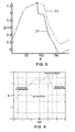
- the POD modes are calculated using all available snapshots, even those that exhibit false shock waves. The regions in the parameter space with and without shock waves in the example being considered are shown in Figure 6 .
- Step 7 Obtaining the POD manifold for the internal shape of the shock wave
- the smooth flow field (SF) exhibits a very different topology on the pressure and suction sides.
- SF smooth flow field
- a better choice consists of using different POD modes (and amplitudes) in the pressure and suction sides.
- the O-mesh is divided into two zones 41, 43, which are as shown in Figure 6 . It must be noted that they share a common sub-region 45 near the leading edge 17.
- the SF is also interpolated using neighboring snapshots, point-by-point, to obtain an initial rough approximation.
- the selected snapshots to evaluate the correlation matrix are the N nearest snapshots with the distance above, where N is a number that is large enough to define the POD manifold; a value of N of the order of the double of the expected POD manifold dimension is a good choice.
- the resulting POD modes on the CFF could lead to large errors in the spatial derivatives of the normal velocity component (perpendicular to the airfoil), which is significantly smaller than the tangential component.
- Step 11 Obtaining an initial guess of the POD amplitudes
- An initial guess (needed in the GA) of the sets of amplitudes, a i , b i , and c i can be calculated by interpolation.
- the initial guess for the GA is obtained by interpolation on the amplitudes of neighboring snapshots.
- the unknown amplitudes a i are calculated upon minimization of a properly defined residual using a Genetic Algorithm (GA).
- GA Genetic Algorithm
- BC 1 ⁇ ⁇ u - M ⁇ ⁇ ⁇ cos AoA
- BC 2 ⁇ ⁇ w - M ⁇ ⁇ ⁇ sin AoA
- BC 3 ⁇ - 1
- B ⁇ C 4 p - 1.
- the selected points can be chosen either randomly or equispaced without losing precision in the results.
- the residual defined above is evaluated using the reconstructed solution in terms of the POD-modes associated with the CFF, using the expansions in terms of these modes given in Step 10 . Note that these modes exhibit unphysical stair-like structures, which are due to the fact that these modes are linear combinations of the original snapshots, which exhibit shock waves. But these modes are used only in the region where the residual is calculated, which excluded the SWR where shock waves exist, as explained above.
- the resulting reconstructed smooth field coincides with the complete field in the leading edge region LER, but not in the trailing edge region TER (see Step 9 for the definition of these regions) and the difference between both in the trailing edge region provides the jump across the shock wave.
- Step 13 GA minimization of a residual to obtain the position, the trace, and the internal structure of the shock wave
- the contour integrals are approximated by the trapezoidal rule.
- cycles The contour integrals are applied over a set of closed curves that will be called cycles below. These cycles have a rectangular shape in the curvilinear (s,n) coordinates and are centered on the initial guess of the shock wave position over the wall. The aspect ratio and number of cycles depend on the structure we are calculating.
- Figure 8a shows the cycle for evaluating the position over the wall.
- Figure 8b shows the cycles for evaluating the trace.
- Figure 8c shows the cycles for evaluating the internal shape. In all cases, cycles are contained in a region that extends vertically from the edge of the upper boundary of the O-mesh, excluding a zone to avoid localized CFD errors; horizontal extension coincides with the SWR. Inside this region, the cycles are as follows:
- calculation of the complete solution involves four independent minimization processes, which can be subsequently applied by the user in an iterative way until the required accuracy is reached. For instance, if the uncertainty on the initial guess of the shock wave position, s w , is not small enough, then the smooth field will be calculated with little accuracy; but after applying the minimization process over the position, a better approximation of s w , will be obtained that will allow a better calculation of the smooth field, which will allow using a smaller uncertainty interval.
- Test Point C L C D C M CFD GAPOD CFD GAPOD CFD GAPOD #11 -0.518 -0.518 0.005 0.004 0.033 0.034 #12 -0.379 -0.380 0.005 0.005 0.033 0.034 #13 -0.033 -0.032 0.005 0.004 0.033 0.034 #14 0.106 0.108 0.005 0.004 0.034 0.034 #21 -0.699 -0.658 0.013 0.012 0.044 0.044 #22 -0.529 -0.499 0.000 0.003 0.038 0.036 #23 -0.044 -0.045 0.003 0.003 0.043 0.044 #24 0.146 0.150 0.001 0.003 0.049 0.050 #31 -0.574 -0.592 0.033 0.032 0.072 0.073 #32 -0.529 -0.515 0.021 0.016 0.072 0.069 #41 -0.500 -0.495 0.040 0.040 0.080
Landscapes
- Engineering & Computer Science (AREA)
- Physics & Mathematics (AREA)
- Theoretical Computer Science (AREA)
- Geometry (AREA)
- General Physics & Mathematics (AREA)
- Computer Hardware Design (AREA)
- General Engineering & Computer Science (AREA)
- Evolutionary Computation (AREA)
- Aviation & Aerospace Engineering (AREA)
- Pure & Applied Mathematics (AREA)
- Mathematical Optimization (AREA)
- Mathematical Analysis (AREA)
- Computational Mathematics (AREA)
- Automation & Control Theory (AREA)
- Aerodynamic Tests, Hydrodynamic Tests, Wind Tunnels, And Water Tanks (AREA)
Applications Claiming Priority (2)
| Application Number | Priority Date | Filing Date | Title |
|---|---|---|---|
| ES200900881 | 2009-03-31 | ||
| PCT/ES2010/070201 WO2010128187A1 (es) | 2009-03-31 | 2010-03-31 | Método y sistema para un cálculo rápido de las fuerzas aerodinámicas en una aeronave en condiciones transónicas |
Publications (1)
| Publication Number | Publication Date |
|---|---|
| EP2434418A1 true EP2434418A1 (de) | 2012-03-28 |
Family
ID=42732402
Family Applications (1)
| Application Number | Title | Priority Date | Filing Date |
|---|---|---|---|
| EP10719016A Withdrawn EP2434418A1 (de) | 2009-03-31 | 2010-03-31 | Verfahren und system zum schnellen berechnen der aerodynamischen kräfte an einem flugzeug in überschallbedingungen |
Country Status (3)
| Country | Link |
|---|---|
| US (1) | US8666715B2 (de) |
| EP (1) | EP2434418A1 (de) |
| WO (1) | WO2010128187A1 (de) |
Cited By (2)
| Publication number | Priority date | Publication date | Assignee | Title |
|---|---|---|---|---|
| CN102880734A (zh) * | 2012-06-21 | 2013-01-16 | 中国人民解放军电子工程学院 | 基于cfd的飞机尾喷流大气扩散建模方法 |
| CN111806720A (zh) * | 2020-06-24 | 2020-10-23 | 成都飞机工业(集团)有限责任公司 | 一种基于翼身对接实测数据的整流蒙皮构造方法 |
Families Citing this family (31)
| Publication number | Priority date | Publication date | Assignee | Title |
|---|---|---|---|---|
| US8457939B2 (en) | 2010-12-30 | 2013-06-04 | Aerion Corporation | Generating inviscid and viscous fluid-flow simulations over an aircraft surface using a fluid-flow mesh |
| US8437990B2 (en) | 2011-03-11 | 2013-05-07 | Aerion Corporation | Generating a simulated fluid flow over an aircraft surface using anisotropic diffusion |
| US8538738B2 (en) | 2011-03-22 | 2013-09-17 | Aerion Corporation | Predicting transition from laminar to turbulent flow over a surface |
| US8892408B2 (en) | 2011-03-23 | 2014-11-18 | Aerion Corporation | Generating inviscid and viscous fluid flow simulations over a surface using a quasi-simultaneous technique |
| FR2995426B1 (fr) * | 2012-09-11 | 2014-09-05 | Airbus Operations Sas | Methode de simulation des charges aerodynamiques instationnaires sur une structure externe d'avion. |
| CN103473422B (zh) * | 2013-09-18 | 2016-03-23 | 成都市永益泵业有限公司 | 基于奇点分布法的轴流叶轮翼型设计方法 |
| US10019474B2 (en) * | 2014-12-11 | 2018-07-10 | Siemens Aktiengesellschaft | Automatic ranking of design parameter significance for fast and accurate CAE-based design space exploration using parameter sensitivity feedback |
| CN104537234B (zh) * | 2014-12-25 | 2018-02-13 | 西北工业大学 | 高低压涡轮过渡流道一维优化设计方法 |
| CN105069245B (zh) * | 2015-08-19 | 2018-04-10 | 中国航天空气动力技术研究院 | 基于多重搜索技术的三维乘波体快速设计方法 |
| CN108763692B (zh) * | 2018-05-18 | 2022-02-18 | 中国舰船研究设计中心 | 一种用于船舶数值水池的高效兴波方法 |
| CN109640080A (zh) * | 2018-11-01 | 2019-04-16 | 广州土圭垚信息科技有限公司 | 一种基于sfla算法的深度图像模式划分简化方法 |
| US11544423B2 (en) * | 2018-12-31 | 2023-01-03 | Dassault Systemes Simulia Corp. | Computer simulation of physical fluids on a mesh in an arbitrary coordinate system |
| CN109933876B (zh) * | 2019-03-03 | 2022-09-09 | 西北工业大学 | 一种基于广义气动力的非定常气动力降阶方法 |
| US11645433B2 (en) | 2019-06-11 | 2023-05-09 | Dassault Systemes Simulia Corp. | Computer simulation of physical fluids on irregular spatial grids stabilized for explicit numerical diffusion problems |
| CN111008492B (zh) * | 2019-11-22 | 2022-10-14 | 电子科技大学 | 一种基于无雅克比矩阵的高阶单元欧拉方程数值模拟方法 |
| AT523439A1 (de) | 2020-01-14 | 2021-07-15 | Peter Leitl | Verfahren zur Herstellung eines mit Riblets auf und/oder in der Oberfläche versehenen Objektes sowie damit hergestelltes Objekt |
| CN111859817B (zh) * | 2020-05-22 | 2024-01-16 | 中国航空工业集团公司西安航空计算技术研究所 | 一种基于cfd软件激波模拟能力的飞行器气动选型方法 |
| CN111859646B (zh) * | 2020-07-09 | 2023-06-09 | 南京理工大学 | 一种基于b样条映射函数物质点法的冲击波变步长求解方法 |
| CN111859645B (zh) * | 2020-07-09 | 2023-03-31 | 南京理工大学 | 冲击波求解的改进musl格式物质点法 |
| CN112711809B (zh) * | 2020-12-29 | 2024-04-09 | 中国航空工业集团公司西安飞机设计研究所 | 一种舵面载荷筛选方法 |
| CN113536457B (zh) * | 2021-07-02 | 2023-05-16 | 北京航空航天大学 | 一种基于状态空间形式涡格法的气动力降阶方法 |
| CN114757113B (zh) * | 2022-03-04 | 2025-07-08 | 中国科学院深圳先进技术研究院 | 一种加力燃烧室的流场分析方法、装置及终端设备 |
| CN114861364B (zh) * | 2022-05-30 | 2025-03-25 | 中国空气动力研究与发展中心空天技术研究所 | 一种吸气式发动机进气道流场智能感知和抽吸调控方法 |
| CN115828797A (zh) * | 2023-02-15 | 2023-03-21 | 中国船舶集团有限公司第七一九研究所 | 一种基于降阶模型的潜艇水动力载荷快速预报方法 |
| CN115994501B (zh) * | 2023-03-23 | 2023-06-06 | 中国人民解放军国防科技大学 | 一种基于多目标优化的航天器返回舱可达边界预测方法 |
| CN116976007B (zh) * | 2023-08-14 | 2024-11-22 | 中南大学 | 一种基于变换热学的飞行器定向疏导热防护层设计方法 |
| CN117390733B (zh) * | 2023-08-28 | 2024-06-11 | 中南大学 | 一种高速铁路隧道口缓冲结构设计方法及系统 |
| CN118821661B (zh) * | 2024-09-18 | 2025-03-07 | 中国海洋大学 | 基于动态模态分解的离心泵空化流场模态降阶方法及系统 |
| CN119756767B (zh) * | 2025-03-04 | 2025-05-23 | 中国空气动力研究与发展中心高速空气动力研究所 | 边条翼布局飞行器的力矩上扬临界迎角预测方法 |
| CN120120591B (zh) * | 2025-05-12 | 2025-07-22 | 清华大学 | 喷气推进装置的径向双v槽流向涡火焰稳定性确定方法 |
| CN121118769B (zh) * | 2025-11-13 | 2026-02-27 | 长春通视光电技术股份有限公司 | 一种光电吊舱的热补偿功率预测模型构建方法和系统 |
Family Cites Families (14)
| Publication number | Priority date | Publication date | Assignee | Title |
|---|---|---|---|---|
| US4080922A (en) * | 1975-09-08 | 1978-03-28 | Brubaker Curtis M | Flyable hydrofoil vessel |
| US5796612A (en) * | 1992-11-18 | 1998-08-18 | Aers/Midwest, Inc. | Method for flight parameter monitoring and control |
| US6002972A (en) * | 1992-11-18 | 1999-12-14 | Aers/Midwest, Inc. | Method and apparatus for measuring forces based upon differential pressure between surfaces of an aircraft |
| DE4422152C2 (de) * | 1994-06-27 | 2000-02-03 | Daimler Chrysler Aerospace | Verfahren und Anordnung zum Optimieren der aerodynamischen Wirkung eines Tragflügels |
| US5875998A (en) * | 1996-02-05 | 1999-03-02 | Daimler-Benz Aerospace Airbus Gmbh | Method and apparatus for optimizing the aerodynamic effect of an airfoil |
| EP0962874A1 (de) * | 1998-06-04 | 1999-12-08 | Asea Brown Boveri AG | Verfahren zum Entwurf von Durchflussvorrichtungen |
| DE19923087B4 (de) * | 1999-05-20 | 2004-02-26 | Eads Deutschland Gmbh | Vorrichtung zur Druck-, Schall- und Vibrationsmessung, sowie Verfahren zur Strömungsanalyse an Bauteiloberflächen |
| US6412732B1 (en) * | 1999-07-06 | 2002-07-02 | Georgia Tech Research Corporation | Apparatus and method for enhancement of aerodynamic performance by using pulse excitation control |
| US7048505B2 (en) * | 2002-06-21 | 2006-05-23 | Darko Segota | Method and system for regulating fluid flow over an airfoil or a hydrofoil |
| US7930073B2 (en) * | 2004-06-23 | 2011-04-19 | Syracuse University | Method and system for controlling airfoil actuators |
| US20060058985A1 (en) * | 2004-08-31 | 2006-03-16 | Supersonic Aerospace International, Llc | Adjoint-based design variable adaptation |
| US7954769B2 (en) * | 2007-12-10 | 2011-06-07 | The Boeing Company | Deployable aerodynamic devices with reduced actuator loads, and related systems and methods |
| ES2356788B1 (es) * | 2007-12-18 | 2012-02-22 | Airbus Operations, S.L. | Método y sistema para un cálculo rápido de las fuerzas aerodinámicas en una aeronave. |
| GB0811942D0 (en) * | 2008-07-01 | 2008-07-30 | Airbus Uk Ltd | Method of designing a structure |
-
2009
- 2009-06-01 US US12/475,682 patent/US8666715B2/en active Active
-
2010
- 2010-03-31 EP EP10719016A patent/EP2434418A1/de not_active Withdrawn
- 2010-03-31 WO PCT/ES2010/070201 patent/WO2010128187A1/es not_active Ceased
Non-Patent Citations (2)
| Title |
|---|
| None * |
| See also references of WO2010128187A1 * |
Cited By (3)
| Publication number | Priority date | Publication date | Assignee | Title |
|---|---|---|---|---|
| CN102880734A (zh) * | 2012-06-21 | 2013-01-16 | 中国人民解放军电子工程学院 | 基于cfd的飞机尾喷流大气扩散建模方法 |
| CN111806720A (zh) * | 2020-06-24 | 2020-10-23 | 成都飞机工业(集团)有限责任公司 | 一种基于翼身对接实测数据的整流蒙皮构造方法 |
| CN111806720B (zh) * | 2020-06-24 | 2021-12-07 | 成都飞机工业(集团)有限责任公司 | 一种基于翼身对接实测数据的整流蒙皮构造方法 |
Also Published As
| Publication number | Publication date |
|---|---|
| US20100250205A1 (en) | 2010-09-30 |
| US8666715B2 (en) | 2014-03-04 |
| WO2010128187A1 (es) | 2010-11-11 |
Similar Documents
| Publication | Publication Date | Title |
|---|---|---|
| US8666715B2 (en) | Method and system for a quick calculation of aerodynamic forces on an aircraft in transonic conditions | |
| US7987081B2 (en) | Method and system for a quick calculation of aerodynamic forces on an aircraft | |
| Hino | A 3D unstructured grid method for incompressible viscous flows | |
| Nishida | Fully simultaneous coupling of the full potential equation and the integral boundary layer equations in three dimensions | |
| Alonso et al. | Reduced-order model for viscous aerodynamic flow past an airfoil | |
| Srinath et al. | Optimal aerodynamic design of airfoils in unsteady viscous flows | |
| Huffman et al. | Practical design and optimization in computational fluid dynamics | |
| Elliott et al. | Aerodynamic optimization on unstructured meshes with viscous effects | |
| Renze et al. | A comparative study of turbulence models for overset grids | |
| Miranda | Application of computational aerodynamics to airplane design | |
| Rudnik et al. | Three-dimensional Navier-Stokes simulations for transport aircraft high-lift configurations | |
| Knight et al. | Development of a viscous cascade code based on scalar implicit factorization | |
| Epstein et al. | Multigrid Euler solver about arbitrary aircraft configurations with Cartesian grids and local refinement | |
| Long | The compressible aerodynamics of rotating blades based on an acoustic formulation | |
| Gordnier et al. | Physical mechanisms for limit-cycle oscillations of a cropped delta wing | |
| Korivi et al. | An incremental strategy for calculating consistent discrete CFD sensitivity derivatives | |
| Lei et al. | CFD validation for high-lift devices: two-element airfoil | |
| Nagati et al. | Vortex sheet modeling with curved higher-order panels | |
| Rampurawala et al. | Evaluation of a simplified grid treatment for oscillating trailing-edge control surfaces | |
| Cole et al. | Wave drag due to lift for transonic airplanes | |
| Haney et al. | Computational optimization and wind tunnel test of transonic wing designs | |
| Sharbatdar | Error estimation and mesh adaptation paradigm for unstructured mesh finite volume methods | |
| Lakshminarayan et al. | Fully Automated Surface Mesh Adaptation in Strand Grid Framework | |
| Bartelheimer | An improved integral equation method for the design of transonic airfoils and wings | |
| Fouladi et al. | Viscous simulation method for unsteady flows past multicomponent configurations |
Legal Events
| Date | Code | Title | Description |
|---|---|---|---|
| PUAI | Public reference made under article 153(3) epc to a published international application that has entered the european phase |
Free format text: ORIGINAL CODE: 0009012 |
|
| 17P | Request for examination filed |
Effective date: 20111027 |
|
| AK | Designated contracting states |
Kind code of ref document: A1 Designated state(s): AT BE BG CH CY CZ DE DK EE ES FI FR GB GR HR HU IE IS IT LI LT LU LV MC MK MT NL NO PL PT RO SE SI SK SM TR |
|
| RIN1 | Information on inventor provided before grant (corrected) |
Inventor name: VEGA DE PRADA, JOSE MANUEL Inventor name: LORENTE MANZANARES, LUIS SANTIAGO Inventor name: DE PABLO FOUCE, VALENTIN Inventor name: ALONSO FERNANDEZ, DIEGO Inventor name: VELAZQUEZ LOPEZ, ANGEL GERARDO |
|
| DAX | Request for extension of the european patent (deleted) | ||
| STAA | Information on the status of an ep patent application or granted ep patent |
Free format text: STATUS: EXAMINATION IS IN PROGRESS |
|
| 17Q | First examination report despatched |
Effective date: 20170620 |
|
| STAA | Information on the status of an ep patent application or granted ep patent |
Free format text: STATUS: THE APPLICATION IS DEEMED TO BE WITHDRAWN |
|
| 18D | Application deemed to be withdrawn |
Effective date: 20181002 |