EP2433828A1 - Sunshade for vehicle - Google Patents
Sunshade for vehicle Download PDFInfo
- Publication number
- EP2433828A1 EP2433828A1 EP11182791A EP11182791A EP2433828A1 EP 2433828 A1 EP2433828 A1 EP 2433828A1 EP 11182791 A EP11182791 A EP 11182791A EP 11182791 A EP11182791 A EP 11182791A EP 2433828 A1 EP2433828 A1 EP 2433828A1
- Authority
- EP
- European Patent Office
- Prior art keywords
- vehicle
- sunshade
- protruding
- extending
- engaging
- Prior art date
- Legal status (The legal status is an assumption and is not a legal conclusion. Google has not performed a legal analysis and makes no representation as to the accuracy of the status listed.)
- Granted
Links
Images


Classifications
-
- B—PERFORMING OPERATIONS; TRANSPORTING
- B60—VEHICLES IN GENERAL
- B60J—WINDOWS, WINDSCREENS, NON-FIXED ROOFS, DOORS, OR SIMILAR DEVICES FOR VEHICLES; REMOVABLE EXTERNAL PROTECTIVE COVERINGS SPECIALLY ADAPTED FOR VEHICLES
- B60J7/00—Non-fixed roofs; Roofs with movable panels, e.g. rotary sunroofs
- B60J7/0007—Non-fixed roofs; Roofs with movable panels, e.g. rotary sunroofs moveable head-liners, screens, curtains or blinds for ceilings
- B60J7/003—Non-fixed roofs; Roofs with movable panels, e.g. rotary sunroofs moveable head-liners, screens, curtains or blinds for ceilings one or more sliding rigid plate or lammellae
- B60J7/0038—Non-fixed roofs; Roofs with movable panels, e.g. rotary sunroofs moveable head-liners, screens, curtains or blinds for ceilings one or more sliding rigid plate or lammellae stored in stacked fashion
Definitions
- This disclosure generally relates to a sunshade for a vehicle.
- a known sunshade for a vehicle is disclosed in JP2010-120537A (referred to as patent reference 1).
- a driving bush provided at a rear edge of an operating side shade panel comes in contact with an engaging bush provided at a front edge and a rear edge of a driven side shade panel to engage thereto.
- the driving bush is made from an elastic member, for example, rubber.
- JP2004-249850A Another known sunshade for a vehicle is disclosed in JP2004-249850A (referred to as patent reference 2).
- a contact pin provided at the rear edge of the operating side shade panel is configured to contact a driven contact pin provided at a front edge of a driven side shade panel to close the driven side shade panel
- a rear edge of the operating side shade panel is configured to contact a rear edge flange portion of the driven side shade panel to open the driven side shade panel.
- the driving bush and the engaging bush are provided on each of shade panels which are readily deformable, in a case where a large load is applied in an upward and downward direction or in a case where each of the shade panels are operated with impetus, the driving bush may overpass the engaging bush and disengage therefrom.
- the disclosure provides a sunshade for a vehicle, which includes a pair of guide rails extended at a side edge of a light passing portion provided on a vehicle roof, the guide rails arranged opposite to each other, plural extending portions formed on each of the guide rails and extending towards the opposite guide rail, the extending portions defining slide recessed grooves, a sliding member supported by the extending portions and slidably provided in each of the slide recessed grooves, an engaging portion formed on said each sliding member, and plural shade panels slidably supported in the slide recessed grooves, respectively, via the sliding member, the shade panels being configured to interoperate each other by an engagement of each of the engaging portions during at least one of an opening operation and a closing operation of the sunshade.
- the engaging portion is provided at the sliding member which is supported by the extending portions, a relative displacement between the sliding members which engage each other is restrained to restrain a disengagement of the sliding members. Further, because the disengagement of the sliding members is restrained, a height of the engaging portion is reduced, and thus a thickness of the sunshade is reduced.
- the extending portions include an upper extending portion extending towards the opposite guide rail to overlap with at least a portion of the engaging portions and formed at an upper portion in an upward-downward direction of the vehicle, a lower extending portion extending towards the opposite guide rail to overlap with at least a portion of the engaging portions and formed at a lower portion in the upward-downward direction of the vehicle, and an intermediate extending portion positioned between the upper extending portion and the lower extending portion in the upward-downward direction of the vehicle and having a shorter extending length compared to the upper extending portion and the lower extending portion.
- the engaging portion is positioned between the upper extending portion and the lower extending portion in the upward-downward direction of the vehicle and in the vicinity of a tip end of the intermediate portion extending towards the opposite guide rail.
- the upper extending portion and the lower extending portion overlap with the engaging portion, a relative displacement between the engaging portions which engage with each other is restrained to securely support the engaging portions. Further, because the engaging portion is positioned in the vicinity of the tip end of the intermediate extending portion, an overlap of the intermediate extending portion with the engaging portion in a thickness direction of the sunshade can be avoided, thus reducing a thickness of the sunshade for the vehicle.
- the engaging portion correspond to a protruding portion protruding in the upward-downward direction of the vehicle.
- the sunshade of the vehicle further includes an elastic member configured to contact the protruding portion with respect to an opening and closing direction of the shade panel.
- the protruding portions are provided with the elastic member, an impact when the protruding portions contact one another is mitigated to retrain a generation of noises.
- an end portion of the protruding portion in the protruding direction in the upward-downward direction of the vehicle protrudes in the protruding direction relative to the elastic member.
- the end portion of the protruding portion in the protruding direction protrudes in the protruding direction relative to the elastic member and a sliding contact between the elastic member and the shade panel can be prevented, a jam or sticking by a trapping of the elastic member is restrained.
- the protruding portion is provided with a retaining groove formed in a recessed configuration on a vertical surface arranged vertical to the opening and closing direction of the sunshade, and the elastic member fits into the retaining groove to be retained therein.
- the elastic member fits into the retaining groove to be securely retained to the protruding portion.
- the elastic member corresponds to a rubber member.
- the sliding member includes a first engaging shoe supported between the upper extending portion and the intermediate extending portion and a second engaging shoe supported between the lower extending portion and the intermediate extending portion
- the plurality of shade panels include a first shade panel slidably supported by the slide recessed groove via the first engaging shoe and a second shade panel slidably supported by the slide recessed groove via the second engaging shoe
- the protruding portion includes a first protruding portion protruding from the first engaging shoe toward the second shade panel and a second protruding portion protruding from the second engaging shoe towards the first shade panel.
- the vertical surface is formed with a pair of stepped portions recessed in a front-rear direction of the vehicle, and the retaining groove is defined by the stepped portion and the shade panel.
- the elastic member corresponds to a rubber member having an opening enclosing a surrounding of the protruding portion.
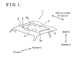
- Fig. 1 is a perspective view of an automobile roof to which a sunshade according to a first embodiment disclosed here is mounted;
- Fig. 2 is a partial plan view showing a fully closed state of the sunshade according to the first embodiment disclosed here;
- Fig. 3 is a cross-sectional view of a guide rail and engaging shoes taken on line III-III in Fig. 2 , the cross section being perpendicular to a vehicle width direction, according to the first embodiment disclosed here;
- Fig. 4 is a cross-sectional view of the guide rail and the engaging shoes taken on line IV-IV in Fig. 2 , the cross section being perpendicular to a front-rear direction of the vehicle, according to the first embodiment disclosed here;
- Fig. 5 is a perspective view of the engaging shoes according to the first embodiment disclosed here.
- Fig. 6 is a cross-sectional view of a guide rail and engaging shoes, the cross section being perpendicular to a front-rear direction of the vehicle, according to a second embodiment disclosed here.
- a sunshade for a vehicle is provided on a roof 1 of an automobile.
- a roof panel 2 forming the roof 1 includes a light passing portion 3 for taking in sunlight and a resin panel 4 made from transparent resin is provided at the light passing portion 3.
- a sealing member is provided at an outer peripheral portion 5 of the resin panel 4 for preventing an infiltration of rainwater to a vehicle compartment.
- a sunshade 11 serving as a sunshade for a vehicle, shown in Fig. 2 is provided at a surface 6 inside the vehicle compartment in the vicinity of a side edge 3a of the light passing portion 3 of the roof panel 2. By opening and closing the sunshade 11, lighting and shielding of the light is performed at the light passing portion 3.
- the sunshade 11 includes a symmetrical configuration and thus the same structure is applied to the other side of the sunshade 11 in the vehicle width direction 12.
- a pair of guide rails 14 which are formed by extruding, for example, aluminum and which extend in a front-rear direction (i.e., serving as an opening and closing direction) are fixed to the surface 6 inside the vehicle compartment in the vicinity of the side edge 3a of the light passing portion 3 of the roof panel 2 by means of, for example, bolts.
- the guide rails 14 are arranged to face each other (i.e., opposite to each other) in the vehicle width direction 12.
- a first shade panel 15 is slidably supported by the guide rails 14 via a pair of first shoes 16 and a pair of first engaging shoes 17 serving as a sliding member, where each of the first shoes 16 is provided at each of the guide rails 14 and each of the engaging shoes 17 is provided at each of the guide rails 14.
- a second shade panel 18 is supported by the guide rails 14 via a pair of second shoes 19 and a pair of second engaging shoes 21 serving as a sliding member, where each of the second shoes 19 is provided at each of the guide rails 14 and each of the second engaging shoes 21 is provided at each of the guide rails 14.
- Each of the first shoes 16 is provided at a front portion of an end portion 15a of the first shade panel 15 in a vehicle width direction.
- Each of the first engaging shoes 17 is provided at a rear portion of the end portion 15a of the first shade panel 15 in the vehicle width direction.
- Each of the second engaging shoes 21 is provided at a front portion of an end portion 18a of the second shade panel 18 in the vehicle width direction.
- Each of the second shoes 19 is provided at a rear portion of the end portion 18a of the second shade panel 18 in the vehicle width direction.
- an operation knob 22 for opening and closing the first shade panel 15 and the second shade panel 18 is provided at a front end portion 15b of the first shade panel 15 at an inside of the vehicle compartment.
- the guide rail 14 includes a first groove portion 14a serving as a sliding recessed groove and a second groove portion 14b serving as a sliding recessed groove which are arranged one on top of the other to be in parallel to each other to extend in a front-rear direction (forward-rearward direction) of the vehicle.
- the first groove portion 14a and the second groove portion 14b are formed to have an opening which opens in an inwards of a vehicle width direction.
- the first groove portion 14a is positioned above the second groove portion 14b.
- the first groove portion 14a is defined by an upper end extending portion 14c (i.e., serving as an extending portion, upper extending portion) extending in the vehicle width direction, an intermediate extending portion 14d (i.e., serving as an extending portion), and a side wall portion 14e extending in an up-down direction (i.e., upward-downward direction) of the vehicle.
- the second groove portion 14b is defined by a lower end extending portion 14f (i.e., serving as an extending portion, a lower extending portion) extending in the vehicle width direction, the intermediate extending portion 14d and the side wall portion 14e.
- a tip end 14g of the upper end extending portion 14c and a tip end 14h of the lower end extending portion 14f are positioned inward in the vehicle width direction relative to a tip end 14i of the intermediate extending portion 14d (i.e., serving as a tip end of an intermediate extending portion).
- An extending length (amount) of the intermediate extending portion 14d in the vehicle width direction is shorter than the upper end extending portion 14c and the lower end extending portion 14f, and a void region 25 is formed in the vicinity of the tip end 14i of the intermediate extending portion 14d.
- the first shoe 16 and the first engaging shoe 17 fit into the first groove portion 14a to slidably support the first shade panel 15.
- the second shoe 19 and the second engaging shoe 21 fit into the second groove portion 14b to slidably support the second shade panel 18.
- a first protruding portion 32 i.e., serving as an engaging portion
- a first rubber member 31 i.e., serving as an elastic member
- the second engaging shoe 21 includes a second protruding portion 34 (i.e., serving as an engaging portion) on which a second rubber member (i.e., serving as an elastic member) is fitted.
- the second protruding portion 34 protrudes in an upward direction of the vehicle.
- a pair of first stepped positions 32b recessed in the front-rear direction of the vehicle is formed on a first vertical surface 32a (i.e., serving as a vertical surface) of the first protruding portion 32 in the front-rear direction of the vehicle.
- the first rubber member 31 includes a first rubber fitting surface 31a, which fits to the first protruding portion 32, and a first rubber retaining portion 31b which is formed protruding in the front-rear direction of the vehicle.
- the first rubber retaining portion 31 b fits into a pair of first rubber retaining grooves 35 (i.e., serving as a retaining groove) defined by the first stepped portions 32b and the first shade panel 15 to retain the first rubber member 31.
- a pair of second stepped portions 34b is formed on a second vertical surface 34a (i.e., serving as a vertical surface) of the second protruding portion 34, and a second rubber retaining groove 36 (i.e., serving as a retaining groove) is defined by the second stepped portion 34b and the second shade panel 18.
- a second rubber retaining portion 33b at a second rubber fitting surface 33a fits into the second rubber retaining groove 36 to retain a second rubber member 33.
- a first protruding surface (i.e., serving as an end portion) 32c is an end surface of the first protruding portion 32 which faces downward and slidably contacts the second shade panel 18.
- a second protruding end surface 34c (i.e., serving as an end portion) is an end surface of the second protruding portion 34 which faces an upward and slidably contacts the first shade panel 15.
- a first contact surface 31 c corresponds to a side surface of the first rubber member 31 which faces the forward direction of the vehicle.
- a second contact surface 33c corresponds to a side surface of the second rubber member 33 which faces the rearward direction of the vehicle and is configured to contact the first contact surface 31 c.
- the first engaging shoe 17 is made of resin and formed in a rectangular shape which extends in the front-rear direction of the vehicle and includes a first shade retaining portion 17a including a recessed portion which opens inwardly in the vehicle width direction.
- the first shade retaining portion 17a is defined by a first upper surface wall portion 17b, a first lower surface wall portion 17c, a first front end portion 17d, a first rear end portion 17e, and a first side wall portion 17f.
- the first lower surface wall portion 17c does not overlap with the first protruding portion 32 in the vehicle width direction, however, the first upper surface wall portion 17b extends in the vehicle width direction to be longer than the first lower surface wall portion 17c so as to overlap with the first protruding portion 32.
- the first protruding portion 32 formed in the rectangular shape extending in the front-rear direction of the vehicle is formed on the first upper surface wall portion 17b via a first protruding leg portion 32d.
- the first protruding portion 32 is positioned in the downward direction of the vehicle relative to the first upper surface wall portion 17b.
- the first protruding portion 32 protrudes in the front-rear direction of the vehicle relative to the first protruding leg portion 32d.
- the first protruding portion 32 is covered with the first rubber member 31 which is formed in a rectangular shape having an opening therein.
- a first protruding end surface 32c corresponds to a crowning curved surface which is curved to protrude in the downward direction of the vehicle.
- the first protruding end surface 32c is arranged to protrude compared to the first rubber member 31 in the downward direction of the vehicle.
- the end portion 15a of the first shade panel 15 in a vehicle width direction which is formed to be recessed so as not to interfere with the first protruding leg portion 32d and the first front end portion 17d fits into the first shade retraining portion 17a to be retained thereat.
- the second engaging shoe 21 includes the identical configuration with the first engaging shoe 17 and is arranged in an inverted position.
- a closing operation of the sunshade 11 will be explained as follows.
- the first shade panel 15 and the second shade panel 18 overlap each other in the up-down direction and are accommodated in a rearward portion of the roof panel 2 on which the light passing portion 3 is not provided.
- the operation knob 22 is operated to apply the force in the forward direction of the vehicle to the first shade panel 15, only the first shade panel 15 slides in the forward direction of the vehicle along the first groove portion 14a via the first shoes 16 and the first engaging shoes 17.
- the first upper surface portion 17b of the first engaging shoe 17 slides relative to the upper end extending portion 14c of the guide rail 14, and the first lower surface wall portion 17c slides relative to the intermediate extending portion 14d.
- first protruding end surface 32c slides relative to the second shade panel 18, and the second protruding end surface 34c slides relative to the first shade panel 15.
- first shade rear end portion 15c comes to closer to a second shade front end portion 18b to overlap each other in the up-down direction of the vehicle
- each of the first engaging shoes 17 and each of the second engaging shoes 21 starts overlapping in the up-down direction of the vehicle.
- a distance between the first protruding portion 32 of the first engaging shoe 17 and the second protruding portion 34 of the second engaging shoes 21 in the front-rear direction of the vehicle is reduced, and the first contact surface 31 c of the first rubber member 31 contacts the second contact surface 33c of the second rubber member 33 in the front-rear direction.
- first protruding portion 32 and the second protruding portion 34 engage with each other in the front-rear direction, and the force applied to the operation knob 22 in the forward direction of the vehicle is transmitted to the second shade panel 18 via the engagement between the first protruding portion 32 and the second protruding portion 34.
- the first shade panel 15 and the second shade panel 18 slide together in the forward direction of the vehicle in a state where the first shade rear end portion 15c and the second shade front end portion 18b overlap each other.
- first upper surface wall portion 17b slides relative to the upper end extending portion 14c
- first lower surface wall portion 17c slides relative to the intermediate extending portion 14d
- a second upper surface wall portion 21 c of the second engaging shoe 21 slides relative to the intermediate extending portion 14d
- a second lower surface wall portion 21 b slides relative to the lower end extending portion 14f.
- first protruding end surface 32c and the second protruding end surface 34c do not slide relative to the first shade panel 15 and the second shade panel 18, respectively.
- the front end portion 15b of the first shade panel 15 comes to contact a stopper to stop moving, and the light passing portion 3 is shielded by the first shade panel 15 and the second shade panel 18 to establish a fully closed state.
- the first protruding portion 32 and the second protruding portion 34 are supported by the upper end extending portion 14c and the lower end extending portion 14f to maintain a relative position in the up-down direction of the vehicle.
- the first shade panel 15 and the second shade panel 18 slide together in a state where the first shade panel 15 and the second shade panel 18 overlap each other, and a rear end portion 18c of the second shade panel 18 contacts a stopper to stop the movement of the first shade panel 15 and the second shade panel 18 to establish the fully open state at which the light can be taken in from the light passing portion 3.
- the first engaging shoe 17 and the second engaging shoe 21 on which the first protruding portion 32 and the second protruding portion 34 serving as the engaging portion are formed, respectively, are supported by the upper end extending portion 14c and the lower end extending portion 14f in the up-down direction of the vehicle.
- a rigidity in the up-down direction of the vehicle when the first protruding portion 32 and the second protruding portion 34 are engaged is enhanced thus restraining a relative displacement of the first protruding portion 32 and the second protruding portion 34.
- the relative displacement is restrained by enhancing the rigidity of the engagement of the first protruding portion 32 and the second protruding portion 34 in the up-down direction of the vehicle, a protruding amount of the first protruding portion 32 and the second protruding portion 34 is reduced, a relative distance between the first engaging shoe 17 and the second engaging shoe 21 in the up-down direction of the vehicle is reduced, and a thickness of the sunshade 11 is reduced.
- the first protruding portion 32 and the second protruding portion 34 are integrally formed with the first engaging shoe 17 and the second engaging shoe 21, respectively, an increase in the number of parts is avoided and manufacturing costs and an assembling time can be reduced.
- the first engaging shoe 17, the second engaging shoe 21, and the guide rail 14 can be applied to the various types of vehicles and only shade panels are changed depending on the types of the vehicle, expansion of the application to different types of vehicles is assumed to be easy, and thus contributing to timely provide a new model to the market.
- the rigidity of the first protruding portion 32 and the second protruding portion 34 when engaged is enhanced to securely support the first protruding portion 32 and the second protruding portion 34.
- the rigidity of the engagement of the first protruding portion 32 and the second protruding portion 34 is enhanced, the rigidity of the first shade panel 15 and the second shade panel 18 is allowed to be reduced, which allows to enhance the degree of freedom in terms of selecting materials and manufacturing costs for materials can be reduced.
- an extending length of the intermediate extending portion 14d in the vehicle width direction is smaller than the upper end extending portion 14c and the lower end extending portion 14f, the void region 25 can be provided in the vicinity of the tip end 14i of the intermediate extending portion 14d.
- first rubber member 31 and the second rubber member 33 are provided on the first protruding portion 32 and the second protruding portion 34, respectively, an impact when the first protruding portion 32 and the second protruding portion 34 contact at the engagement therebetween is mitigated to restrain a generation of noises, thus enhancing quietness.
- the first protruding end surface 32c and the second protruding end surface 34c protrude relative to the first rubber member 31 and the second rubber member 33, respectively, in protruding directions of the first protruding portion 32 and the second protruding portion 34.
- the opening and closing operation of the sunshade 11 is performed without a direct sliding contact between the first rubber member 31 and the second shade panel 18, and between the second rubber member 33 and the first shade panel 15. Accordingly, a generation of a jam or sticking due to trapping of the first rubber member 31 and the second rubber member 33 when opening and closing the sunshade 11 is restrained, which smoothes an operational feeling and enhances texture. Further, a generation of noises by a stick-slip phenomenon caused by a sliding movement of rubber members over the panels can be restrained, thus enhancing quietness.
- first rubber member 31 and the second rubber member 33 fit into the first rubber retaining groove 35 and the second rubber retaining groove 36, respectively, the first rubber member 31 and the second rubber member 33 are securely retained at the first protruding portion 32 and the second protruding portion 34. Further, by fitting the first rubber member 31 and the second rubber member 33 into the first rubber-retaining groove 35 and the second rubber-retaining groove 36, positioning is readily determined and an assembling accuracy is enhanced.
- the first rubber member 31 and the second rubber member 33 are fixed to the first rubber retaining groove 35 and the second rubber retaining groove 36, respectively, formed on the first vertical surface 32a and the second vertical surface 34a, respectively.
- the first rubber member 31 and the second rubber member 33 may be fixed to surfaces other than the first vertical surface 32a and the second vertical surface 34a.
- a fixing method is not limited to the fitting engagement, and, for example, the first rubber member 31 and the second rubber member 33 may be fixed to the surfaces by bonding.
- the first rubber member 31 and the second rubber member 33 are provided at the first protruding portion 32 and the second protruding portion 34, respectively.
- an elastic member may be provided on only one of the first protruding portion 32 and the second protruding portion 34.
- the first protruding portion 32 and the second protruding portion 34 may be made of, for example, resin having high acoustic absorption performance and a high damping ratio. Further, a portion having a large degree of deforming amount may be integrally formed on the first protruding portion 32 and the second protruding portion 34 to absorb an impact.
- first protruding end surface 32c and the second protruding end surface 34c protrude in the up-down direction of the vehicle.
- first protruding end surface 32c and the second protruding end surface 34c may be structured so that a portion of the surfaces of the first protruding end surface 32c and the second protruding end surface 34c protrude in the up-down direction of the vehicle.
- the first engaging shoe 17 and the second engaging shoe 21 are configured to engage each other during the closing operation of the sunshade 11.
- the construction is not limited to the foregoing, and the first engaging shoe 17 and the second engaging shoe 21 may be configured to engage each other during the opening operation of the sunshade 11. Further, the first engaging shoe 17 and the second engaging shoe 21 may be configured to engage each other both during the closing operation and during the opening operation of the sunshade 11.
- the resin panel 4 is provided separately from the roof panel 2.
- the construction is not limited to the foregoing, and the resin panel 4 and the roof panel 2 may be integrally formed.
- the sunshade 11 is applied for selectively taking in the light for a fixed type sunroof.
- the sunshade 11 may be applied to other types of sunroofs, for example, a flip out type sunroof which is a sliding type or fixed by a hinge.
- the sunshade 11 may be opened and closed manually or by an electric actuation.
- two shade panels are provided, however, the number of the shade panels is not limited.
- three or more shade panels may be provided by increasing the number of steps of the sliding recessed groove so as to be applicable to, for example, a van type vehicle having a large roof dimension.
- a modified example of the sunshade for the vehicle having four shade panels, a first shade panel 41, a second shade panel 42, a third shade panel 43, and a fourth shade panel 44 is shown in Fig. 6.
- Fig. 6 shows a cross-sectional view of a guide rail 45, and the first to fourth shade panels 41-44 on a surface vertical to a front-rear direction of the vehicle.
- a first extending portion 45a i.e., serving as an upper extending portion
- a second extending portion 45b i.e., serving as an intermediate extending portion
- a third extending portion 45c i.e., serving as an upper extending portion, a lower extending portion
- a fourth extending portion 45d i.e., serving as an intermediate extending portion
- a fifth extending portion 45e i.e., serving as a lower extending portion
- the third extending portion 45c positioned at a middle portion of the guide rail 45 in the up-down direction of the vehicle serves as the lower extending portion to support a first protruding portion (i.e., serving as an engaging portion) and a second protruding portion 51 (i.e., serving as an engaging portion) together with the first extending portion 45a, and the third extending portion 45c serves as the upper extending portion to support a third protruding portion (i.e., serving as an engaging portion) and a fourth protruding portion 52 (i.e., serving as an engaging portion) together with the fifth extending portion 45e.
- a first protruding portion i.e., serving as an engaging portion
- a second protruding portion 51 i.e., serving as an engaging portion
- the third extending portion 45c serves as the upper extending portion to support a third protruding portion (i.e., serving as an engaging portion) and a fourth protruding portion 52 (i.e.
- the vertical surface which is vertical to the opening and closing direction is not necessarily formed in a precisely vertical surface in the opening and closing direction, and is defined to include a surface having a deviation of an angle to some extent.
Landscapes
- Engineering & Computer Science (AREA)
- Mechanical Engineering (AREA)
- Closing And Opening Devices For Wings, And Checks For Wings (AREA)
- Seal Device For Vehicle (AREA)
- Body Structure For Vehicles (AREA)
- Support Devices For Sliding Doors (AREA)
Abstract
Description
- This disclosure generally relates to a sunshade for a vehicle.
- A known sunshade for a vehicle is disclosed in
JP2010-120537A patent reference 1, in order to open and close multiple shade panels, which slide along separate grooves, respectively, of a guide rail, interoperating with each other, a driving bush provided at a rear edge of an operating side shade panel comes in contact with an engaging bush provided at a front edge and a rear edge of a driven side shade panel to engage thereto. For the purpose of reducing an impact noise which is generated when the driving bush contacts the engaging bush, the driving bush is made from an elastic member, for example, rubber. - Another known sunshade for a vehicle is disclosed in
JP2004-249850A patent reference 2, a contact pin provided at the rear edge of the operating side shade panel is configured to contact a driven contact pin provided at a front edge of a driven side shade panel to close the driven side shade panel, and a rear edge of the operating side shade panel is configured to contact a rear edge flange portion of the driven side shade panel to open the driven side shade panel. - However, according to the sunshade for the vehicle disclosed in the
patent reference 1, because the driving bush and the engaging bush are provided on each of shade panels which are readily deformable, in a case where a large load is applied in an upward and downward direction or in a case where each of the shade panels are operated with impetus, the driving bush may overpass the engaging bush and disengage therefrom. - Further, according to the sunshade for the vehicle disclosed in the
patent reference 2, because the contact pin and the driven contact pin are positioned between the operating side shade panel and the driven side shade panel, a thickness of the multiple-plates sunshade is increased. - A need thus exists for a sunshade for a vehicle which restrains unintentional disengagement of bushes and reduces a thickness of a multiple-plates sunshade.
- In light of the foregoing, the disclosure provides a sunshade for a vehicle, which includes a pair of guide rails extended at a side edge of a light passing portion provided on a vehicle roof, the guide rails arranged opposite to each other, plural extending portions formed on each of the guide rails and extending towards the opposite guide rail, the extending portions defining slide recessed grooves, a sliding member supported by the extending portions and slidably provided in each of the slide recessed grooves, an engaging portion formed on said each sliding member, and plural shade panels slidably supported in the slide recessed grooves, respectively, via the sliding member, the shade panels being configured to interoperate each other by an engagement of each of the engaging portions during at least one of an opening operation and a closing operation of the sunshade.
- According to the construction of the disclosure, because the engaging portion is provided at the sliding member which is supported by the extending portions, a relative displacement between the sliding members which engage each other is restrained to restrain a disengagement of the sliding members. Further, because the disengagement of the sliding members is restrained, a height of the engaging portion is reduced, and thus a thickness of the sunshade is reduced.
- According to the discourse, the extending portions include an upper extending portion extending towards the opposite guide rail to overlap with at least a portion of the engaging portions and formed at an upper portion in an upward-downward direction of the vehicle, a lower extending portion extending towards the opposite guide rail to overlap with at least a portion of the engaging portions and formed at a lower portion in the upward-downward direction of the vehicle, and an intermediate extending portion positioned between the upper extending portion and the lower extending portion in the upward-downward direction of the vehicle and having a shorter extending length compared to the upper extending portion and the lower extending portion. The engaging portion is positioned between the upper extending portion and the lower extending portion in the upward-downward direction of the vehicle and in the vicinity of a tip end of the intermediate portion extending towards the opposite guide rail.
- According to the construction of the disclosure, because the upper extending portion and the lower extending portion overlap with the engaging portion, a relative displacement between the engaging portions which engage with each other is restrained to securely support the engaging portions. Further, because the engaging portion is positioned in the vicinity of the tip end of the intermediate extending portion, an overlap of the intermediate extending portion with the engaging portion in a thickness direction of the sunshade can be avoided, thus reducing a thickness of the sunshade for the vehicle.
- According to the disclosure, the engaging portion correspond to a protruding portion protruding in the upward-downward direction of the vehicle. The sunshade of the vehicle further includes an elastic member configured to contact the protruding portion with respect to an opening and closing direction of the shade panel.
- According to the construction of the disclosure, because the protruding portions are provided with the elastic member, an impact when the protruding portions contact one another is mitigated to retrain a generation of noises.
- According to the disclosure, an end portion of the protruding portion in the protruding direction in the upward-downward direction of the vehicle protrudes in the protruding direction relative to the elastic member.
- According to the construction of the disclosure, because the end portion of the protruding portion in the protruding direction protrudes in the protruding direction relative to the elastic member and a sliding contact between the elastic member and the shade panel can be prevented, a jam or sticking by a trapping of the elastic member is restrained.
- According to the disclosure, the protruding portion is provided with a retaining groove formed in a recessed configuration on a vertical surface arranged vertical to the opening and closing direction of the sunshade, and the elastic member fits into the retaining groove to be retained therein.
- According to the construction of the disclosure, the elastic member fits into the retaining groove to be securely retained to the protruding portion.
- According to the disclosure, the elastic member corresponds to a rubber member.
- According to the disclosure, the sliding member includes a first engaging shoe supported between the upper extending portion and the intermediate extending portion and a second engaging shoe supported between the lower extending portion and the intermediate extending portion, the plurality of shade panels include a first shade panel slidably supported by the slide recessed groove via the first engaging shoe and a second shade panel slidably supported by the slide recessed groove via the second engaging shoe, and the protruding portion includes a first protruding portion protruding from the first engaging shoe toward the second shade panel and a second protruding portion protruding from the second engaging shoe towards the first shade panel.
- According to the disclosure, the vertical surface is formed with a pair of stepped portions recessed in a front-rear direction of the vehicle, and the retaining groove is defined by the stepped portion and the shade panel.
- According to the disclosure, the elastic member corresponds to a rubber member having an opening enclosing a surrounding of the protruding portion.
- The foregoing and additional features and characteristics of this disclosure will become more apparent from the following detailed description considered with the reference to the accompanying drawings, wherein:
-
Fig. 1 is a perspective view of an automobile roof to which a sunshade according to a first embodiment disclosed here is mounted; -
Fig. 2 is a partial plan view showing a fully closed state of the sunshade according to the first embodiment disclosed here; -
Fig. 3 is a cross-sectional view of a guide rail and engaging shoes taken on line III-III inFig. 2 , the cross section being perpendicular to a vehicle width direction, according to the first embodiment disclosed here; -
Fig. 4 is a cross-sectional view of the guide rail and the engaging shoes taken on line IV-IV inFig. 2 , the cross section being perpendicular to a front-rear direction of the vehicle, according to the first embodiment disclosed here; -
Fig. 5 is a perspective view of the engaging shoes according to the first embodiment disclosed here; and -
Fig. 6 is a cross-sectional view of a guide rail and engaging shoes, the cross section being perpendicular to a front-rear direction of the vehicle, according to a second embodiment disclosed here. - Embodiments of a sunshade for a vehicle will be explained with reference to illustrations of drawing figures as follows.
- As shown in
Fig. 1 , a sunshade for a vehicle according to the embodiment is provided on aroof 1 of an automobile. Aroof panel 2 forming theroof 1 includes alight passing portion 3 for taking in sunlight and a resin panel 4 made from transparent resin is provided at thelight passing portion 3. A sealing member is provided at an outerperipheral portion 5 of the resin panel 4 for preventing an infiltration of rainwater to a vehicle compartment. Asunshade 11 serving as a sunshade for a vehicle, shown inFig. 2 , is provided at asurface 6 inside the vehicle compartment in the vicinity of aside edge 3a of thelight passing portion 3 of theroof panel 2. By opening and closing thesunshade 11, lighting and shielding of the light is performed at thelight passing portion 3. - For an explanatory purpose, only one side of the
sunshade 11 in a vehicle width direction 12 is shown inFigs. 2 to 6 , thesunshade 11 includes a symmetrical configuration and thus the same structure is applied to the other side of thesunshade 11 in the vehicle width direction 12. A pair ofguide rails 14 which are formed by extruding, for example, aluminum and which extend in a front-rear direction (i.e., serving as an opening and closing direction) are fixed to thesurface 6 inside the vehicle compartment in the vicinity of theside edge 3a of thelight passing portion 3 of theroof panel 2 by means of, for example, bolts. Theguide rails 14 are arranged to face each other (i.e., opposite to each other) in the vehicle width direction 12. Afirst shade panel 15 is slidably supported by theguide rails 14 via a pair offirst shoes 16 and a pair of firstengaging shoes 17 serving as a sliding member, where each of thefirst shoes 16 is provided at each of theguide rails 14 and each of theengaging shoes 17 is provided at each of theguide rails 14. Asecond shade panel 18 is supported by theguide rails 14 via a pair ofsecond shoes 19 and a pair of secondengaging shoes 21 serving as a sliding member, where each of thesecond shoes 19 is provided at each of theguide rails 14 and each of the secondengaging shoes 21 is provided at each of theguide rails 14. Each of thefirst shoes 16 is provided at a front portion of anend portion 15a of thefirst shade panel 15 in a vehicle width direction. Each of the firstengaging shoes 17 is provided at a rear portion of theend portion 15a of thefirst shade panel 15 in the vehicle width direction. Each of the secondengaging shoes 21 is provided at a front portion of anend portion 18a of thesecond shade panel 18 in the vehicle width direction. Each of thesecond shoes 19 is provided at a rear portion of theend portion 18a of thesecond shade panel 18 in the vehicle width direction. Further, anoperation knob 22 for opening and closing thefirst shade panel 15 and thesecond shade panel 18 is provided at afront end portion 15b of thefirst shade panel 15 at an inside of the vehicle compartment. - As shown in
Figs. 3 and4 , theguide rail 14 includes afirst groove portion 14a serving as a sliding recessed groove and asecond groove portion 14b serving as a sliding recessed groove which are arranged one on top of the other to be in parallel to each other to extend in a front-rear direction (forward-rearward direction) of the vehicle. Thefirst groove portion 14a and thesecond groove portion 14b are formed to have an opening which opens in an inwards of a vehicle width direction. Thefirst groove portion 14a is positioned above thesecond groove portion 14b. Thefirst groove portion 14a is defined by an upperend extending portion 14c (i.e., serving as an extending portion, upper extending portion) extending in the vehicle width direction, an intermediate extendingportion 14d (i.e., serving as an extending portion), and aside wall portion 14e extending in an up-down direction (i.e., upward-downward direction) of the vehicle. Thesecond groove portion 14b is defined by a lowerend extending portion 14f (i.e., serving as an extending portion, a lower extending portion) extending in the vehicle width direction, the intermediate extendingportion 14d and theside wall portion 14e. Atip end 14g of the upperend extending portion 14c and atip end 14h of the lowerend extending portion 14f are positioned inward in the vehicle width direction relative to atip end 14i of the intermediate extendingportion 14d (i.e., serving as a tip end of an intermediate extending portion). An extending length (amount) of theintermediate extending portion 14d in the vehicle width direction is shorter than the upperend extending portion 14c and the lowerend extending portion 14f, and avoid region 25 is formed in the vicinity of thetip end 14i of the intermediate extendingportion 14d. - The
first shoe 16 and the firstengaging shoe 17 fit into thefirst groove portion 14a to slidably support thefirst shade panel 15. Thesecond shoe 19 and the secondengaging shoe 21 fit into thesecond groove portion 14b to slidably support thesecond shade panel 18. A first protruding portion 32 (i.e., serving as an engaging portion) on which a first rubber member 31 (i.e., serving as an elastic member) is fitted is provided on the firstengaging shoe 17 to protrude in a downward direction of the vehicle. The secondengaging shoe 21 includes a second protruding portion 34 (i.e., serving as an engaging portion) on which a second rubber member (i.e., serving as an elastic member) is fitted. The second protrudingportion 34 protrudes in an upward direction of the vehicle. A pair of first steppedpositions 32b recessed in the front-rear direction of the vehicle is formed on a firstvertical surface 32a (i.e., serving as a vertical surface) of the first protrudingportion 32 in the front-rear direction of the vehicle. Thefirst rubber member 31 includes a firstrubber fitting surface 31a, which fits to the first protrudingportion 32, and a firstrubber retaining portion 31b which is formed protruding in the front-rear direction of the vehicle. The firstrubber retaining portion 31 b fits into a pair of first rubber retaining grooves 35 (i.e., serving as a retaining groove) defined by the first steppedportions 32b and thefirst shade panel 15 to retain thefirst rubber member 31. Similarly, a pair of second steppedportions 34b is formed on a secondvertical surface 34a (i.e., serving as a vertical surface) of the second protrudingportion 34, and a second rubber retaining groove 36 (i.e., serving as a retaining groove) is defined by the second steppedportion 34b and thesecond shade panel 18. A secondrubber retaining portion 33b at a secondrubber fitting surface 33a fits into the secondrubber retaining groove 36 to retain asecond rubber member 33. A first protruding surface (i.e., serving as an end portion) 32c is an end surface of the first protrudingportion 32 which faces downward and slidably contacts thesecond shade panel 18. A secondprotruding end surface 34c (i.e., serving as an end portion) is an end surface of the second protrudingportion 34 which faces an upward and slidably contacts thefirst shade panel 15. Afirst contact surface 31 c corresponds to a side surface of thefirst rubber member 31 which faces the forward direction of the vehicle. Asecond contact surface 33c corresponds to a side surface of thesecond rubber member 33 which faces the rearward direction of the vehicle and is configured to contact thefirst contact surface 31 c. Because thetip end 14g of the upperend extending portion 14c and thetip end 14h of the lowerend extending portion 14f overlap with the first protrudingportion 32 and the second protrudingportion 34, the first protrudingportion 32 and the second protrudingportion 34 are supported by theguide rail 14 in an up-down direction of the vehicle, and are positioned within thevoid region 25. In those circumstances, that thetip end 14g of the upperend extending portion 14c and thetip end 14h of the lowerend extending portion 14f overlap with the first protrudingportion 32 and the second protrudingportion 34 corresponds to that the upperend extending portion 14c and thetip end 14h of the lowerend extending portion 14f are piled in the up-down direction of the vehicle relative to the first protrudingportion 32 and the second protrudingportion 34. - As illustrated in
Fig. 5 , the first engagingshoe 17 is made of resin and formed in a rectangular shape which extends in the front-rear direction of the vehicle and includes a firstshade retaining portion 17a including a recessed portion which opens inwardly in the vehicle width direction. The firstshade retaining portion 17a is defined by a first uppersurface wall portion 17b, a first lowersurface wall portion 17c, a firstfront end portion 17d, a firstrear end portion 17e, and a firstside wall portion 17f. The first lowersurface wall portion 17c does not overlap with the first protrudingportion 32 in the vehicle width direction, however, the first uppersurface wall portion 17b extends in the vehicle width direction to be longer than the first lowersurface wall portion 17c so as to overlap with the first protrudingportion 32. The first protrudingportion 32 formed in the rectangular shape extending in the front-rear direction of the vehicle is formed on the first uppersurface wall portion 17b via a firstprotruding leg portion 32d. The first protrudingportion 32 is positioned in the downward direction of the vehicle relative to the first uppersurface wall portion 17b. The first protrudingportion 32 protrudes in the front-rear direction of the vehicle relative to the firstprotruding leg portion 32d. The first protrudingportion 32 is covered with thefirst rubber member 31 which is formed in a rectangular shape having an opening therein. A firstprotruding end surface 32c corresponds to a crowning curved surface which is curved to protrude in the downward direction of the vehicle. The firstprotruding end surface 32c is arranged to protrude compared to thefirst rubber member 31 in the downward direction of the vehicle. Theend portion 15a of thefirst shade panel 15 in a vehicle width direction which is formed to be recessed so as not to interfere with the firstprotruding leg portion 32d and the firstfront end portion 17d fits into the firstshade retraining portion 17a to be retained thereat. The secondengaging shoe 21 includes the identical configuration with the first engagingshoe 17 and is arranged in an inverted position. - A closing operation of the
sunshade 11 will be explained as follows. In a fully open state of thesunshade 11, thefirst shade panel 15 and thesecond shade panel 18 overlap each other in the up-down direction and are accommodated in a rearward portion of theroof panel 2 on which thelight passing portion 3 is not provided. When theoperation knob 22 is operated to apply the force in the forward direction of the vehicle to thefirst shade panel 15, only thefirst shade panel 15 slides in the forward direction of the vehicle along thefirst groove portion 14a via thefirst shoes 16 and the first engaging shoes 17. In those circumstances, the firstupper surface portion 17b of the first engagingshoe 17 slides relative to the upperend extending portion 14c of theguide rail 14, and the first lowersurface wall portion 17c slides relative to the intermediate extendingportion 14d. Further, the firstprotruding end surface 32c slides relative to thesecond shade panel 18, and the secondprotruding end surface 34c slides relative to thefirst shade panel 15. As a first shaderear end portion 15c comes to closer to a second shadefront end portion 18b to overlap each other in the up-down direction of the vehicle, each of the firstengaging shoes 17 and each of the secondengaging shoes 21 starts overlapping in the up-down direction of the vehicle. Then, a distance between the first protrudingportion 32 of the first engagingshoe 17 and the second protrudingportion 34 of the secondengaging shoes 21 in the front-rear direction of the vehicle is reduced, and thefirst contact surface 31 c of thefirst rubber member 31 contacts thesecond contact surface 33c of thesecond rubber member 33 in the front-rear direction. Thus, the first protrudingportion 32 and the second protrudingportion 34 engage with each other in the front-rear direction, and the force applied to theoperation knob 22 in the forward direction of the vehicle is transmitted to thesecond shade panel 18 via the engagement between the first protrudingportion 32 and the second protrudingportion 34. Thefirst shade panel 15 and thesecond shade panel 18 slide together in the forward direction of the vehicle in a state where the first shaderear end portion 15c and the second shadefront end portion 18b overlap each other. In those circumstances, the first uppersurface wall portion 17b slides relative to the upperend extending portion 14c, the first lowersurface wall portion 17c slides relative to the intermediate extendingportion 14d, a second uppersurface wall portion 21 c of the second engagingshoe 21 slides relative to the intermediate extendingportion 14d, and a second lowersurface wall portion 21 b slides relative to the lowerend extending portion 14f. Further, the firstprotruding end surface 32c and the secondprotruding end surface 34c do not slide relative to thefirst shade panel 15 and thesecond shade panel 18, respectively. Thefront end portion 15b of thefirst shade panel 15 comes to contact a stopper to stop moving, and thelight passing portion 3 is shielded by thefirst shade panel 15 and thesecond shade panel 18 to establish a fully closed state. Further, even in a case where a force in the up-down direction of the vehicle to disengage the first engagingshoe 17 and the second engagingshoe 21 is applied, for example, when the first protrudingportion 32 and the second protrudingportion 34 contact each other with impetus, or with force, the first protrudingportion 32 and the second protrudingportion 34 are supported by the upperend extending portion 14c and the lowerend extending portion 14f to maintain a relative position in the up-down direction of the vehicle. - An opening operation of the
sunshade 11 will be explained as follows. When opening the sunshade, upon the application of the force to theoperation knob 22 in the rearward direction of the vehicle, the engagement of the first protrudingportion 32 and the second protrudingportion 34 is canceled, and only thefirst shade panel 15 slides in the rearward direction. By contacting thefirst shoe 16 of thefirst shade panel 15 to the second engagingshoe 21 of thesecond shade panel 18, thefirst shoe 16 and the second engagingshoe 21 are engaged in the front-rear direction of the vehicle. Thefirst shade panel 15 and thesecond shade panel 18 slide together in a state where thefirst shade panel 15 and thesecond shade panel 18 overlap each other, and arear end portion 18c of thesecond shade panel 18 contacts a stopper to stop the movement of thefirst shade panel 15 and thesecond shade panel 18 to establish the fully open state at which the light can be taken in from thelight passing portion 3. - According to the construction of the
sunshade 11, the first engagingshoe 17 and the second engagingshoe 21 on which the first protrudingportion 32 and the second protrudingportion 34 serving as the engaging portion are formed, respectively, are supported by the upperend extending portion 14c and the lowerend extending portion 14f in the up-down direction of the vehicle. According to the foregoing construction, compared to a construction that the first protrudingportion 32 and the second protrudingportion 34 are provided on thefirst shade panel 15 and thesecond shade panel 18 whose rigidity is lower than the first engagingshoe 17 and the second engagingshoe 21, a rigidity in the up-down direction of the vehicle when the first protrudingportion 32 and the second protrudingportion 34 are engaged is enhanced thus restraining a relative displacement of the first protrudingportion 32 and the second protrudingportion 34. Thus, even if the first protrudingportion 32 and the second protrudingportion 34 roughly contact each other, the relative displacement of the first protrudingportion 32 and the second protrudingportion 34 in the up-down direction of the vehicle is restrained, thus enhancing a certainty of the engagement by restraining the disengagement. Further, because the relative displacement is restrained by enhancing the rigidity of the engagement of the first protrudingportion 32 and the second protrudingportion 34 in the up-down direction of the vehicle, a protruding amount of the first protrudingportion 32 and the second protrudingportion 34 is reduced, a relative distance between the first engagingshoe 17 and the second engagingshoe 21 in the up-down direction of the vehicle is reduced, and a thickness of thesunshade 11 is reduced. Further, because the first protrudingportion 32 and the second protrudingportion 34 are integrally formed with the first engagingshoe 17 and the second engagingshoe 21, respectively, an increase in the number of parts is avoided and manufacturing costs and an assembling time can be reduced. Further, when applying a sunshade to various types of vehicles, the first engagingshoe 17, the second engagingshoe 21, and theguide rail 14 can be applied to the various types of vehicles and only shade panels are changed depending on the types of the vehicle, expansion of the application to different types of vehicles is assumed to be easy, and thus contributing to timely provide a new model to the market. - Further, by extending the upper
end extending portion 14c and the lowerend extending portion 14f in the vehicle width direction so that thetip end 14g of the upperend extending portion 14c and thetip end 14h of the lowerend extending portion 14f overlap with the first protrudingportion 32 and the second protrudingportion 34, the rigidity of the first protrudingportion 32 and the second protrudingportion 34 when engaged is enhanced to securely support the first protrudingportion 32 and the second protrudingportion 34. Because the rigidity of the engagement of the first protrudingportion 32 and the second protrudingportion 34 is enhanced, the rigidity of thefirst shade panel 15 and thesecond shade panel 18 is allowed to be reduced, which allows to enhance the degree of freedom in terms of selecting materials and manufacturing costs for materials can be reduced. Further, because an extending length of the intermediate extendingportion 14d in the vehicle width direction is smaller than the upperend extending portion 14c and the lowerend extending portion 14f, thevoid region 25 can be provided in the vicinity of thetip end 14i of the intermediate extendingportion 14d. By accommodating the first protrudingportion 32 and the second protrudingportion 34 within thevoid region 25, a thickness of thesunshade 11 can be reduced. Thus, even if thesunshade 11 is provided at the roof, space over a head of a driver and occupants is not reduced, and a comfortable headroom can be maintained. - Further, because the
first rubber member 31 and thesecond rubber member 33 are provided on the first protrudingportion 32 and the second protrudingportion 34, respectively, an impact when the first protrudingportion 32 and the second protrudingportion 34 contact at the engagement therebetween is mitigated to restrain a generation of noises, thus enhancing quietness. - The first
protruding end surface 32c and the secondprotruding end surface 34c protrude relative to thefirst rubber member 31 and thesecond rubber member 33, respectively, in protruding directions of the first protrudingportion 32 and the second protrudingportion 34. According to the foregoing construction, the opening and closing operation of thesunshade 11 is performed without a direct sliding contact between thefirst rubber member 31 and thesecond shade panel 18, and between thesecond rubber member 33 and thefirst shade panel 15. Accordingly, a generation of a jam or sticking due to trapping of thefirst rubber member 31 and thesecond rubber member 33 when opening and closing thesunshade 11 is restrained, which smoothes an operational feeling and enhances texture. Further, a generation of noises by a stick-slip phenomenon caused by a sliding movement of rubber members over the panels can be restrained, thus enhancing quietness. - Further, because the
first rubber member 31 and thesecond rubber member 33 fit into the firstrubber retaining groove 35 and the secondrubber retaining groove 36, respectively, thefirst rubber member 31 and thesecond rubber member 33 are securely retained at the first protrudingportion 32 and the second protrudingportion 34. Further, by fitting thefirst rubber member 31 and thesecond rubber member 33 into the first rubber-retaininggroove 35 and the second rubber-retaininggroove 36, positioning is readily determined and an assembling accuracy is enhanced. - The above-explained embodiment may be modified as follows.
- According to the foregoing embodiment, the
first rubber member 31 and thesecond rubber member 33 are fixed to the firstrubber retaining groove 35 and the secondrubber retaining groove 36, respectively, formed on the firstvertical surface 32a and the secondvertical surface 34a, respectively. However, thefirst rubber member 31 and thesecond rubber member 33 may be fixed to surfaces other than the firstvertical surface 32a and the secondvertical surface 34a. Further, a fixing method is not limited to the fitting engagement, and, for example, thefirst rubber member 31 and thesecond rubber member 33 may be fixed to the surfaces by bonding. - According to the embodiment, the
first rubber member 31 and thesecond rubber member 33 are provided at the first protrudingportion 32 and the second protrudingportion 34, respectively. However, an elastic member may be provided on only one of the first protrudingportion 32 and the second protrudingportion 34. Alternatively, instead of providing the elastic member, the first protrudingportion 32 and the second protrudingportion 34 may be made of, for example, resin having high acoustic absorption performance and a high damping ratio. Further, a portion having a large degree of deforming amount may be integrally formed on the first protrudingportion 32 and the second protrudingportion 34 to absorb an impact. - According to the embodiment, entire surfaces of the first
protruding end surface 32c and the secondprotruding end surface 34c protrude in the up-down direction of the vehicle. However, the firstprotruding end surface 32c and the secondprotruding end surface 34c may be structured so that a portion of the surfaces of the firstprotruding end surface 32c and the secondprotruding end surface 34c protrude in the up-down direction of the vehicle. - According to the embodiment, the first engaging
shoe 17 and the second engagingshoe 21 are configured to engage each other during the closing operation of thesunshade 11. However, the construction is not limited to the foregoing, and the first engagingshoe 17 and the second engagingshoe 21 may be configured to engage each other during the opening operation of thesunshade 11. Further, the first engagingshoe 17 and the second engagingshoe 21 may be configured to engage each other both during the closing operation and during the opening operation of thesunshade 11. - According to the embodiment, the resin panel 4 is provided separately from the
roof panel 2. However, the construction is not limited to the foregoing, and the resin panel 4 and theroof panel 2 may be integrally formed. - According to the embodiment, the
sunshade 11 is applied for selectively taking in the light for a fixed type sunroof. However, thesunshade 11 may be applied to other types of sunroofs, for example, a flip out type sunroof which is a sliding type or fixed by a hinge. Further, thesunshade 11 may be opened and closed manually or by an electric actuation. - According to the embodiment, two shade panels are provided, however, the number of the shade panels is not limited. For example, three or more shade panels may be provided by increasing the number of steps of the sliding recessed groove so as to be applicable to, for example, a van type vehicle having a large roof dimension. Alternatively, a modified example of the sunshade for the vehicle having four shade panels, a
first shade panel 41, asecond shade panel 42, athird shade panel 43, and afourth shade panel 44 is shown inFig. 6. Fig. 6 shows a cross-sectional view of aguide rail 45, and the first to fourth shade panels 41-44 on a surface vertical to a front-rear direction of the vehicle. A first extendingportion 45a (i.e., serving as an upper extending portion), a second extendingportion 45b (i.e., serving as an intermediate extending portion), a third extendingportion 45c (i.e., serving as an upper extending portion, a lower extending portion), a fourth extendingportion 45d (i.e., serving as an intermediate extending portion), and a fifth extendingportion 45e (i.e., serving as a lower extending portion) are formed on theguide rail 45. Theshade panels 41 to 44 are supported (retained) by the first through fifth extendingportions 45a to 45e via engagingshoes 46 to 49. The third extendingportion 45c positioned at a middle portion of theguide rail 45 in the up-down direction of the vehicle serves as the lower extending portion to support a first protruding portion (i.e., serving as an engaging portion) and a second protruding portion 51 (i.e., serving as an engaging portion) together with the first extendingportion 45a, and the third extendingportion 45c serves as the upper extending portion to support a third protruding portion (i.e., serving as an engaging portion) and a fourth protruding portion 52 (i.e., serving as an engaging portion) together with the fifth extendingportion 45e. - According to the construction of the disclosure, the vertical surface which is vertical to the opening and closing direction is not necessarily formed in a precisely vertical surface in the opening and closing direction, and is defined to include a surface having a deviation of an angle to some extent.
Claims (9)
- A sunshade for a vehicle, comprising:a pair of guide rails (14, 45) extended at a side edge of a light passing portion provided on a vehicle roof, the guide rails arranged opposite to each other;a plurality of extending portions (14c, 14d, 14f; 45a, 45b, 45c, 45d, 45e) formed on each of the guide rails (14, 45) and extending towards the opposite guide rail, the extending portions defining slide recessed grooves (14a, 14b);a sliding member (17, 21) supported by the extending portions and slidably provided in each of the slide recessed grooves (14a, 14b);an engaging portion (32, 34; 51, 52) formed on said each sliding member (17, 21); anda plurality of shade panels (15, 18) slidably supported in the slide recessed grooves (14a, 14b), respectively, via the sliding member (17, 21), the shade panels (15, 18) being configured to interoperate each other by an engagement of each of the engaging portions during at least one of an opening operation and a closing operation of the sunshade.
- The sunshade for the vehicle, according to claim 1, wherein
the extending portions include an upper extending portion (14c; 45a, 45c) extending towards the opposite guide rail to overlap with at least a portion of the engaging portions (32, 34) and formed at an upper portion in an upward-downward direction of the vehicle, a lower extending portion (14f; 45c, 45e) extending towards the opposite guide rail to overlap with at least a portion of the engaging portions (32, 34) and formed at a lower portion in the upward-downward direction of the vehicle, and an intermediate extending portion (14d; 45b, 45d) positioned between the upper extending portion and the lower extending portion in the upward-downward direction of the vehicle and having a shorter extending length compared to the upper extending portion and the lower extending portion; and wherein
the engaging portion is positioned between the upper extending portion and the lower extending portion in the upward-downward direction of the vehicle and in the vicinity of a tip end of the intermediate portion extending towards the opposite guide rail. - The sunshade for the vehicle, according to either claim 1 or 2, wherein the engaging portion (32, 34) correspond, to a protruding portion (32, 34) protruding in the upward-downward direction of the vehicle; further comprising
an elastic member (31, 33) configured to contact the protruding portion with respect to an opening and closing direction of the shade panel. - The sunshade for the vehicle according to claim 3, wherein an end portion of the protruding portion in the protruding direction in the upward-downward direction of the vehicle protrudes in the protruding direction relative to the elastic member.
- The sunshade for the vehicle according to any one of claims 1 to 4, wherein the protruding portion is provided with a retaining groove (35, 36) formed in a recessed configuration on a vertical surface arranged vertical to the opening and closing direction of the sunshade; and wherein
the elastic member fits into the retaining groove to be retained therein. - The sunshade for the vehicle according to any one of claims 3 to 5, wherein the elastic member corresponds to a rubber member.
- The sunshade for the vehicle according to any one of claims 3 to 6, wherein
the sliding member (17, 21) includes a first engaging shoe (17) supported between the upper extending portion (14c; 45a, 45c) and the intermediate extending portion (14d; 45b, 45d) and a second engaging shoe (21) supported between the lower extending portion (14f; 45c, 45e) and the intermediate extending portion (14d; 45b, 45d);
the plurality of shade panels (15, 18) include a first shade panel (15) slidably supported by the slide recessed groove (14a) via the first engaging shoe and a second shade panel (18) slidably supported by the slide recessed groove (14b) via the second engaging shoe; and
the protruding portion (32, 34) includes a first protruding portion (32) protruding from the first engaging shoe toward the second shade panel and a second protruding portion (34) protruding from the second engaging shoe towards the first shade panel. - The sunshade for the vehicle according to claim 5, wherein the vertical surface is formed with a pair of stepped portions recessed in a front-rear direction of the vehicle, and the retaining groove (35, 36) is defined by the stepped portion and the shade panel.
- The sunshade for the vehicle according to claim 6, wherein the elastic member (31, 33) corresponds to a rubber member having an opening enclosing a surrounding of the protruding portion.
Applications Claiming Priority (1)
| Application Number | Priority Date | Filing Date | Title |
|---|---|---|---|
| JP2010217137A JP5617488B2 (en) | 2010-09-28 | 2010-09-28 | Sunshade for vehicle |
Publications (2)
| Publication Number | Publication Date |
|---|---|
| EP2433828A1 true EP2433828A1 (en) | 2012-03-28 |
| EP2433828B1 EP2433828B1 (en) | 2013-07-31 |
Family
ID=44785501
Family Applications (1)
| Application Number | Title | Priority Date | Filing Date |
|---|---|---|---|
| EP11182791.1A Not-in-force EP2433828B1 (en) | 2010-09-28 | 2011-09-26 | Sunshade for vehicle |
Country Status (4)
| Country | Link |
|---|---|
| US (1) | US8434817B2 (en) |
| EP (1) | EP2433828B1 (en) |
| JP (1) | JP5617488B2 (en) |
| CN (1) | CN102431424B (en) |
Families Citing this family (11)
| Publication number | Priority date | Publication date | Assignee | Title |
|---|---|---|---|---|
| US8408274B2 (en) | 2009-10-26 | 2013-04-02 | Rajiva Dwarka | Architectural apparatus and method |
| US20160319593A1 (en) * | 2011-05-11 | 2016-11-03 | Rajiva A. Dwarka | Retractable curtain panel with track guide |
| US20170009524A1 (en) * | 2011-05-11 | 2017-01-12 | Rajiva A. Dwarka | Retractable curtain panel and enhanced stiffeners |
| US20130068400A1 (en) * | 2011-05-11 | 2013-03-21 | Rajiva A. Dwarka | Retractable curtain panel with track guide |
| US9347258B2 (en) * | 2011-05-11 | 2016-05-24 | Rajiva A. Dwarka | Retractable curtain panel with track guide |
| US9249621B2 (en) | 2012-01-18 | 2016-02-02 | Rajiva A. Dwarka | Coil brush curtain assembly |
| US9080362B2 (en) * | 2013-09-06 | 2015-07-14 | Kohler Co. | Shower door bumper |
| JP6347187B2 (en) * | 2014-09-08 | 2018-06-27 | 株式会社豊田自動織機 | Stopper structure for vehicle sunshade |
| JP6361487B2 (en) * | 2014-12-03 | 2018-07-25 | 株式会社豊田自動織機 | Vehicle sunshade device |
| KR102030296B1 (en) * | 2018-11-26 | 2019-10-08 | 금영성 | Auto sunshield device for vehicle |
| JP7113791B2 (en) * | 2019-07-30 | 2022-08-05 | 近畿車輌株式会社 | Opening and closing structure of air regulation plate |
Citations (2)
| Publication number | Priority date | Publication date | Assignee | Title |
|---|---|---|---|---|
| JP2004249850A (en) | 2003-02-20 | 2004-09-09 | Aisin Seiki Co Ltd | Roof trim for vehicle |
| EP2189315A2 (en) * | 2008-11-20 | 2010-05-26 | Aisin Seiki Kabushiki Kaisha | Shade apparatus for vehicle |
Family Cites Families (16)
| Publication number | Priority date | Publication date | Assignee | Title |
|---|---|---|---|---|
| US2602693A (en) * | 1948-11-24 | 1952-07-08 | Richard J Murphy | Sliding closure |
| DE1630330A1 (en) * | 1967-08-03 | 1971-06-09 | Daimler Benz Ag | Plastic sliding jaws for sliding roofs of motor vehicles that slide in profiles |
| DE2553549C3 (en) * | 1975-11-28 | 1983-11-03 | Webasto-Werk W. Baier GmbH & Co, 8035 Gauting | Slide shoe for a vehicle sunroof |
| JPS59172016U (en) * | 1983-05-02 | 1984-11-17 | トヨタ自動車株式会社 | Sunroof sunshield device |
| US5005899A (en) * | 1988-07-18 | 1991-04-09 | Asha Corporation | Vehicle transparent roof having manually operable sunshade |
| JPH0261720U (en) * | 1988-10-31 | 1990-05-08 | ||
| CA2049797C (en) * | 1991-08-23 | 1996-05-07 | Andre T. Leitert | Cushioned stop member for sliding panel |
| US6012767A (en) * | 1995-03-29 | 2000-01-11 | Meritor Light Vehicles Systems, Inc. | Louver arrangement for vehicle sun roofs |
| US5816647A (en) * | 1996-03-27 | 1998-10-06 | Westmont Technik Gmbh & Co. Kg | Louver arrangement for vehicle sun roofs, especially transparent ones |
| JP3561831B2 (en) * | 1998-06-15 | 2004-09-02 | 株式会社大井製作所 | Sunshade device for vehicles |
| DE29820613U1 (en) * | 1998-11-18 | 2000-03-30 | Meritor Automotive Gmbh | Sunroof for vehicles |
| JP2004249851A (en) * | 2003-02-20 | 2004-09-09 | Aisin Seiki Co Ltd | Roof device for vehicle |
| EP1634746A1 (en) * | 2004-09-14 | 2006-03-15 | Grupo Antolin-Ingenieria, S.A. | Sunshade with blades for vehicle roofs |
| JP2006168575A (en) * | 2004-12-16 | 2006-06-29 | Toyota Auto Body Co Ltd | Sun shade device for vehicle |
| JP4654858B2 (en) * | 2005-09-26 | 2011-03-23 | アイシン精機株式会社 | Sunroof device |
| US7416245B2 (en) * | 2005-12-27 | 2008-08-26 | Yachiyo Kogyo Kabushiki Kaisya | Sunshade device for vehicle |
-
2010
- 2010-09-28 JP JP2010217137A patent/JP5617488B2/en not_active Expired - Fee Related
-
2011
- 2011-09-23 US US13/200,352 patent/US8434817B2/en not_active Expired - Fee Related
- 2011-09-26 EP EP11182791.1A patent/EP2433828B1/en not_active Not-in-force
- 2011-09-26 CN CN201110293537.8A patent/CN102431424B/en not_active Expired - Fee Related
Patent Citations (3)
| Publication number | Priority date | Publication date | Assignee | Title |
|---|---|---|---|---|
| JP2004249850A (en) | 2003-02-20 | 2004-09-09 | Aisin Seiki Co Ltd | Roof trim for vehicle |
| EP2189315A2 (en) * | 2008-11-20 | 2010-05-26 | Aisin Seiki Kabushiki Kaisha | Shade apparatus for vehicle |
| JP2010120537A (en) | 2008-11-20 | 2010-06-03 | Aisin Seiki Co Ltd | Shade apparatus for vehicle |
Also Published As
| Publication number | Publication date |
|---|---|
| EP2433828B1 (en) | 2013-07-31 |
| US20120073768A1 (en) | 2012-03-29 |
| JP2012071655A (en) | 2012-04-12 |
| JP5617488B2 (en) | 2014-11-05 |
| US8434817B2 (en) | 2013-05-07 |
| CN102431424A (en) | 2012-05-02 |
| CN102431424B (en) | 2015-01-21 |
Similar Documents
| Publication | Publication Date | Title |
|---|---|---|
| EP2433828B1 (en) | Sunshade for vehicle | |
| EP3007919B1 (en) | Window panel support structure | |
| US8282159B2 (en) | Roof apparatus for vehicle | |
| JP6371269B2 (en) | Vehicle door glass lifting structure | |
| US7661710B2 (en) | Blind member for vehicle, and gap-closing structure including blind member | |
| KR20150120336A (en) | Plastic Stiffening Panel For A Door, Comprising A Mounting Mechanism For A Window Lift System | |
| JP6001304B2 (en) | Sunroof device | |
| US20090072588A1 (en) | Vehicle sun roof system | |
| US9121205B2 (en) | Vehicle door fixing apparatus | |
| WO2006090851A1 (en) | Glass guide structure for vehicle | |
| JP4465000B2 (en) | Sunroof device | |
| CN108608841B (en) | Device for preventing dust from entering rear rail of skylight | |
| US20110120020A1 (en) | Device for closing off a window made in a motor vehicle, corresponding roof and corresponding vehicle | |
| US7416245B2 (en) | Sunshade device for vehicle | |
| EP2189315B1 (en) | Shade apparatus for vehicle | |
| KR101466467B1 (en) | Opening and closing apparatus for sunroof | |
| JP2009262893A (en) | Vehicular door | |
| JP6392833B2 (en) | Door structure | |
| JP2020079520A (en) | Opening/closing body support structure of vehicle door | |
| GB2386868A (en) | Seat assembly incorporating vehicle partition | |
| US11193320B2 (en) | Window regulator assembly | |
| WO2015040707A1 (en) | Door structure | |
| WO2020184541A1 (en) | Cover member, and cover member attachment structure | |
| JP2551226Y2 (en) | Sliding window device for vehicles | |
| JP5173497B2 (en) | Sliding window |
Legal Events
| Date | Code | Title | Description |
|---|---|---|---|
| PUAI | Public reference made under article 153(3) epc to a published international application that has entered the european phase |
Free format text: ORIGINAL CODE: 0009012 |
|
| AK | Designated contracting states |
Kind code of ref document: A1 Designated state(s): AL AT BE BG CH CY CZ DE DK EE ES FI FR GB GR HR HU IE IS IT LI LT LU LV MC MK MT NL NO PL PT RO RS SE SI SK SM TR |
|
| AX | Request for extension of the european patent |
Extension state: BA ME |
|
| 17P | Request for examination filed |
Effective date: 20120925 |
|
| GRAP | Despatch of communication of intention to grant a patent |
Free format text: ORIGINAL CODE: EPIDOSNIGR1 |
|
| GRAS | Grant fee paid |
Free format text: ORIGINAL CODE: EPIDOSNIGR3 |
|
| GRAA | (expected) grant |
Free format text: ORIGINAL CODE: 0009210 |
|
| AK | Designated contracting states |
Kind code of ref document: B1 Designated state(s): AL AT BE BG CH CY CZ DE DK EE ES FI FR GB GR HR HU IE IS IT LI LT LU LV MC MK MT NL NO PL PT RO RS SE SI SK SM TR |
|
| REG | Reference to a national code |
Ref country code: GB Ref legal event code: FG4D Ref country code: CH Ref legal event code: EP |
|
| REG | Reference to a national code |
Ref country code: AT Ref legal event code: REF Ref document number: 624392 Country of ref document: AT Kind code of ref document: T Effective date: 20130815 |
|
| REG | Reference to a national code |
Ref country code: IE Ref legal event code: FG4D |
|
| REG | Reference to a national code |
Ref country code: DE Ref legal event code: R096 Ref document number: 602011002520 Country of ref document: DE Effective date: 20130926 |
|
| REG | Reference to a national code |
Ref country code: AT Ref legal event code: MK05 Ref document number: 624392 Country of ref document: AT Kind code of ref document: T Effective date: 20130731 |
|
| REG | Reference to a national code |
Ref country code: NL Ref legal event code: VDEP Effective date: 20130731 |
|
| REG | Reference to a national code |
Ref country code: LT Ref legal event code: MG4D |
|
| PG25 | Lapsed in a contracting state [announced via postgrant information from national office to epo] |
Ref country code: HR Free format text: LAPSE BECAUSE OF FAILURE TO SUBMIT A TRANSLATION OF THE DESCRIPTION OR TO PAY THE FEE WITHIN THE PRESCRIBED TIME-LIMIT Effective date: 20130731 Ref country code: IS Free format text: LAPSE BECAUSE OF FAILURE TO SUBMIT A TRANSLATION OF THE DESCRIPTION OR TO PAY THE FEE WITHIN THE PRESCRIBED TIME-LIMIT Effective date: 20131130 Ref country code: AT Free format text: LAPSE BECAUSE OF FAILURE TO SUBMIT A TRANSLATION OF THE DESCRIPTION OR TO PAY THE FEE WITHIN THE PRESCRIBED TIME-LIMIT Effective date: 20130731 Ref country code: SE Free format text: LAPSE BECAUSE OF FAILURE TO SUBMIT A TRANSLATION OF THE DESCRIPTION OR TO PAY THE FEE WITHIN THE PRESCRIBED TIME-LIMIT Effective date: 20130731 Ref country code: PT Free format text: LAPSE BECAUSE OF FAILURE TO SUBMIT A TRANSLATION OF THE DESCRIPTION OR TO PAY THE FEE WITHIN THE PRESCRIBED TIME-LIMIT Effective date: 20131202 Ref country code: LT Free format text: LAPSE BECAUSE OF FAILURE TO SUBMIT A TRANSLATION OF THE DESCRIPTION OR TO PAY THE FEE WITHIN THE PRESCRIBED TIME-LIMIT Effective date: 20130731 Ref country code: CY Free format text: LAPSE BECAUSE OF FAILURE TO SUBMIT A TRANSLATION OF THE DESCRIPTION OR TO PAY THE FEE WITHIN THE PRESCRIBED TIME-LIMIT Effective date: 20130814 Ref country code: NO Free format text: LAPSE BECAUSE OF FAILURE TO SUBMIT A TRANSLATION OF THE DESCRIPTION OR TO PAY THE FEE WITHIN THE PRESCRIBED TIME-LIMIT Effective date: 20131031 Ref country code: BE Free format text: LAPSE BECAUSE OF FAILURE TO SUBMIT A TRANSLATION OF THE DESCRIPTION OR TO PAY THE FEE WITHIN THE PRESCRIBED TIME-LIMIT Effective date: 20130731 |
|
| PG25 | Lapsed in a contracting state [announced via postgrant information from national office to epo] |
Ref country code: LV Free format text: LAPSE BECAUSE OF FAILURE TO SUBMIT A TRANSLATION OF THE DESCRIPTION OR TO PAY THE FEE WITHIN THE PRESCRIBED TIME-LIMIT Effective date: 20130731 Ref country code: PL Free format text: LAPSE BECAUSE OF FAILURE TO SUBMIT A TRANSLATION OF THE DESCRIPTION OR TO PAY THE FEE WITHIN THE PRESCRIBED TIME-LIMIT Effective date: 20130731 Ref country code: GR Free format text: LAPSE BECAUSE OF FAILURE TO SUBMIT A TRANSLATION OF THE DESCRIPTION OR TO PAY THE FEE WITHIN THE PRESCRIBED TIME-LIMIT Effective date: 20131101 Ref country code: FI Free format text: LAPSE BECAUSE OF FAILURE TO SUBMIT A TRANSLATION OF THE DESCRIPTION OR TO PAY THE FEE WITHIN THE PRESCRIBED TIME-LIMIT Effective date: 20130731 Ref country code: NL Free format text: LAPSE BECAUSE OF FAILURE TO SUBMIT A TRANSLATION OF THE DESCRIPTION OR TO PAY THE FEE WITHIN THE PRESCRIBED TIME-LIMIT Effective date: 20130731 Ref country code: SI Free format text: LAPSE BECAUSE OF FAILURE TO SUBMIT A TRANSLATION OF THE DESCRIPTION OR TO PAY THE FEE WITHIN THE PRESCRIBED TIME-LIMIT Effective date: 20130731 |
|
| PG25 | Lapsed in a contracting state [announced via postgrant information from national office to epo] |
Ref country code: CY Free format text: LAPSE BECAUSE OF FAILURE TO SUBMIT A TRANSLATION OF THE DESCRIPTION OR TO PAY THE FEE WITHIN THE PRESCRIBED TIME-LIMIT Effective date: 20130731 |
|
| PG25 | Lapsed in a contracting state [announced via postgrant information from national office to epo] |
Ref country code: DK Free format text: LAPSE BECAUSE OF FAILURE TO SUBMIT A TRANSLATION OF THE DESCRIPTION OR TO PAY THE FEE WITHIN THE PRESCRIBED TIME-LIMIT Effective date: 20130731 Ref country code: EE Free format text: LAPSE BECAUSE OF FAILURE TO SUBMIT A TRANSLATION OF THE DESCRIPTION OR TO PAY THE FEE WITHIN THE PRESCRIBED TIME-LIMIT Effective date: 20130731 Ref country code: SK Free format text: LAPSE BECAUSE OF FAILURE TO SUBMIT A TRANSLATION OF THE DESCRIPTION OR TO PAY THE FEE WITHIN THE PRESCRIBED TIME-LIMIT Effective date: 20130731 Ref country code: RO Free format text: LAPSE BECAUSE OF FAILURE TO SUBMIT A TRANSLATION OF THE DESCRIPTION OR TO PAY THE FEE WITHIN THE PRESCRIBED TIME-LIMIT Effective date: 20130731 Ref country code: MC Free format text: LAPSE BECAUSE OF FAILURE TO SUBMIT A TRANSLATION OF THE DESCRIPTION OR TO PAY THE FEE WITHIN THE PRESCRIBED TIME-LIMIT Effective date: 20130731 Ref country code: CZ Free format text: LAPSE BECAUSE OF FAILURE TO SUBMIT A TRANSLATION OF THE DESCRIPTION OR TO PAY THE FEE WITHIN THE PRESCRIBED TIME-LIMIT Effective date: 20130731 |
|
| PG25 | Lapsed in a contracting state [announced via postgrant information from national office to epo] |
Ref country code: ES Free format text: LAPSE BECAUSE OF FAILURE TO SUBMIT A TRANSLATION OF THE DESCRIPTION OR TO PAY THE FEE WITHIN THE PRESCRIBED TIME-LIMIT Effective date: 20130731 Ref country code: IT Free format text: LAPSE BECAUSE OF FAILURE TO SUBMIT A TRANSLATION OF THE DESCRIPTION OR TO PAY THE FEE WITHIN THE PRESCRIBED TIME-LIMIT Effective date: 20130731 |
|
| PLBE | No opposition filed within time limit |
Free format text: ORIGINAL CODE: 0009261 |
|
| STAA | Information on the status of an ep patent application or granted ep patent |
Free format text: STATUS: NO OPPOSITION FILED WITHIN TIME LIMIT |
|
| REG | Reference to a national code |
Ref country code: FR Ref legal event code: ST Effective date: 20140530 |
|
| REG | Reference to a national code |
Ref country code: IE Ref legal event code: MM4A |
|
| 26N | No opposition filed |
Effective date: 20140502 |
|
| PG25 | Lapsed in a contracting state [announced via postgrant information from national office to epo] |
Ref country code: IE Free format text: LAPSE BECAUSE OF NON-PAYMENT OF DUE FEES Effective date: 20130926 |
|
| REG | Reference to a national code |
Ref country code: DE Ref legal event code: R097 Ref document number: 602011002520 Country of ref document: DE Effective date: 20140502 |
|
| PG25 | Lapsed in a contracting state [announced via postgrant information from national office to epo] |
Ref country code: FR Free format text: LAPSE BECAUSE OF NON-PAYMENT OF DUE FEES Effective date: 20130930 |
|
| REG | Reference to a national code |
Ref country code: CH Ref legal event code: PL |
|
| PG25 | Lapsed in a contracting state [announced via postgrant information from national office to epo] |
Ref country code: SM Free format text: LAPSE BECAUSE OF FAILURE TO SUBMIT A TRANSLATION OF THE DESCRIPTION OR TO PAY THE FEE WITHIN THE PRESCRIBED TIME-LIMIT Effective date: 20130731 |
|
| PG25 | Lapsed in a contracting state [announced via postgrant information from national office to epo] |
Ref country code: TR Free format text: LAPSE BECAUSE OF FAILURE TO SUBMIT A TRANSLATION OF THE DESCRIPTION OR TO PAY THE FEE WITHIN THE PRESCRIBED TIME-LIMIT Effective date: 20130731 Ref country code: MT Free format text: LAPSE BECAUSE OF FAILURE TO SUBMIT A TRANSLATION OF THE DESCRIPTION OR TO PAY THE FEE WITHIN THE PRESCRIBED TIME-LIMIT Effective date: 20130731 |
|
| PG25 | Lapsed in a contracting state [announced via postgrant information from national office to epo] |
Ref country code: LU Free format text: LAPSE BECAUSE OF NON-PAYMENT OF DUE FEES Effective date: 20130926 Ref country code: LI Free format text: LAPSE BECAUSE OF NON-PAYMENT OF DUE FEES Effective date: 20140930 Ref country code: RS Free format text: LAPSE BECAUSE OF FAILURE TO SUBMIT A TRANSLATION OF THE DESCRIPTION OR TO PAY THE FEE WITHIN THE PRESCRIBED TIME-LIMIT Effective date: 20131031 Ref country code: BG Free format text: LAPSE BECAUSE OF FAILURE TO SUBMIT A TRANSLATION OF THE DESCRIPTION OR TO PAY THE FEE WITHIN THE PRESCRIBED TIME-LIMIT Effective date: 20130731 Ref country code: HU Free format text: LAPSE BECAUSE OF FAILURE TO SUBMIT A TRANSLATION OF THE DESCRIPTION OR TO PAY THE FEE WITHIN THE PRESCRIBED TIME-LIMIT; INVALID AB INITIO Effective date: 20110926 Ref country code: CH Free format text: LAPSE BECAUSE OF NON-PAYMENT OF DUE FEES Effective date: 20140930 Ref country code: MK Free format text: LAPSE BECAUSE OF FAILURE TO SUBMIT A TRANSLATION OF THE DESCRIPTION OR TO PAY THE FEE WITHIN THE PRESCRIBED TIME-LIMIT Effective date: 20130731 |
|
| GBPC | Gb: european patent ceased through non-payment of renewal fee |
Effective date: 20150926 |
|
| PG25 | Lapsed in a contracting state [announced via postgrant information from national office to epo] |
Ref country code: GB Free format text: LAPSE BECAUSE OF NON-PAYMENT OF DUE FEES Effective date: 20150926 |
|
| PG25 | Lapsed in a contracting state [announced via postgrant information from national office to epo] |
Ref country code: AL Free format text: LAPSE BECAUSE OF FAILURE TO SUBMIT A TRANSLATION OF THE DESCRIPTION OR TO PAY THE FEE WITHIN THE PRESCRIBED TIME-LIMIT Effective date: 20130731 |
|
| PGFP | Annual fee paid to national office [announced via postgrant information from national office to epo] |
Ref country code: DE Payment date: 20190910 Year of fee payment: 9 |
|
| REG | Reference to a national code |
Ref country code: DE Ref legal event code: R119 Ref document number: 602011002520 Country of ref document: DE |
|
| PG25 | Lapsed in a contracting state [announced via postgrant information from national office to epo] |
Ref country code: DE Free format text: LAPSE BECAUSE OF NON-PAYMENT OF DUE FEES Effective date: 20210401 |