EP2433036B1 - Drehdurchführung mit geringer gasdurchlässigkeit - Google Patents
Drehdurchführung mit geringer gasdurchlässigkeit Download PDFInfo
- Publication number
- EP2433036B1 EP2433036B1 EP10721670.7A EP10721670A EP2433036B1 EP 2433036 B1 EP2433036 B1 EP 2433036B1 EP 10721670 A EP10721670 A EP 10721670A EP 2433036 B1 EP2433036 B1 EP 2433036B1
- Authority
- EP
- European Patent Office
- Prior art keywords
- sealing
- sealing device
- rotary feedthrough
- adjusting shaft
- eine
- Prior art date
- Legal status (The legal status is an assumption and is not a legal conclusion. Google has not performed a legal analysis and makes no representation as to the accuracy of the status listed.)
- Active
Links
Images






Classifications
-
- F—MECHANICAL ENGINEERING; LIGHTING; HEATING; WEAPONS; BLASTING
- F16—ENGINEERING ELEMENTS AND UNITS; GENERAL MEASURES FOR PRODUCING AND MAINTAINING EFFECTIVE FUNCTIONING OF MACHINES OR INSTALLATIONS; THERMAL INSULATION IN GENERAL
- F16J—PISTONS; CYLINDERS; SEALINGS
- F16J15/00—Sealings
- F16J15/16—Sealings between relatively-moving surfaces
- F16J15/32—Sealings between relatively-moving surfaces with elastic sealings, e.g. O-rings
- F16J15/3204—Sealings between relatively-moving surfaces with elastic sealings, e.g. O-rings with at least one lip
-
- F—MECHANICAL ENGINEERING; LIGHTING; HEATING; WEAPONS; BLASTING
- F16—ENGINEERING ELEMENTS AND UNITS; GENERAL MEASURES FOR PRODUCING AND MAINTAINING EFFECTIVE FUNCTIONING OF MACHINES OR INSTALLATIONS; THERMAL INSULATION IN GENERAL
- F16J—PISTONS; CYLINDERS; SEALINGS
- F16J15/00—Sealings
- F16J15/16—Sealings between relatively-moving surfaces
- F16J15/32—Sealings between relatively-moving surfaces with elastic sealings, e.g. O-rings
- F16J15/3204—Sealings between relatively-moving surfaces with elastic sealings, e.g. O-rings with at least one lip
- F16J15/3228—Sealings between relatively-moving surfaces with elastic sealings, e.g. O-rings with at least one lip formed by deforming a flat ring
-
- F—MECHANICAL ENGINEERING; LIGHTING; HEATING; WEAPONS; BLASTING
- F16—ENGINEERING ELEMENTS AND UNITS; GENERAL MEASURES FOR PRODUCING AND MAINTAINING EFFECTIVE FUNCTIONING OF MACHINES OR INSTALLATIONS; THERMAL INSULATION IN GENERAL
- F16J—PISTONS; CYLINDERS; SEALINGS
- F16J15/00—Sealings
- F16J15/16—Sealings between relatively-moving surfaces
- F16J15/32—Sealings between relatively-moving surfaces with elastic sealings, e.g. O-rings
- F16J15/3284—Sealings between relatively-moving surfaces with elastic sealings, e.g. O-rings characterised by their structure; Selection of materials
-
- F—MECHANICAL ENGINEERING; LIGHTING; HEATING; WEAPONS; BLASTING
- F16—ENGINEERING ELEMENTS AND UNITS; GENERAL MEASURES FOR PRODUCING AND MAINTAINING EFFECTIVE FUNCTIONING OF MACHINES OR INSTALLATIONS; THERMAL INSULATION IN GENERAL
- F16J—PISTONS; CYLINDERS; SEALINGS
- F16J15/00—Sealings
- F16J15/16—Sealings between relatively-moving surfaces
- F16J15/34—Sealings between relatively-moving surfaces with slip-ring pressed against a more or less radial face on one member
- F16J15/3436—Pressing means
-
- F—MECHANICAL ENGINEERING; LIGHTING; HEATING; WEAPONS; BLASTING
- F16—ENGINEERING ELEMENTS AND UNITS; GENERAL MEASURES FOR PRODUCING AND MAINTAINING EFFECTIVE FUNCTIONING OF MACHINES OR INSTALLATIONS; THERMAL INSULATION IN GENERAL
- F16J—PISTONS; CYLINDERS; SEALINGS
- F16J15/00—Sealings
- F16J15/16—Sealings between relatively-moving surfaces
- F16J15/34—Sealings between relatively-moving surfaces with slip-ring pressed against a more or less radial face on one member
- F16J15/3496—Sealings between relatively-moving surfaces with slip-ring pressed against a more or less radial face on one member use of special materials
-
- F—MECHANICAL ENGINEERING; LIGHTING; HEATING; WEAPONS; BLASTING
- F16—ENGINEERING ELEMENTS AND UNITS; GENERAL MEASURES FOR PRODUCING AND MAINTAINING EFFECTIVE FUNCTIONING OF MACHINES OR INSTALLATIONS; THERMAL INSULATION IN GENERAL
- F16J—PISTONS; CYLINDERS; SEALINGS
- F16J15/00—Sealings
- F16J15/50—Sealings between relatively-movable members, by means of a sealing without relatively-moving surfaces, e.g. fluid-tight sealings for transmitting motion through a wall
-
- F—MECHANICAL ENGINEERING; LIGHTING; HEATING; WEAPONS; BLASTING
- F16—ENGINEERING ELEMENTS AND UNITS; GENERAL MEASURES FOR PRODUCING AND MAINTAINING EFFECTIVE FUNCTIONING OF MACHINES OR INSTALLATIONS; THERMAL INSULATION IN GENERAL
- F16J—PISTONS; CYLINDERS; SEALINGS
- F16J15/00—Sealings
- F16J15/50—Sealings between relatively-movable members, by means of a sealing without relatively-moving surfaces, e.g. fluid-tight sealings for transmitting motion through a wall
- F16J15/52—Sealings between relatively-movable members, by means of a sealing without relatively-moving surfaces, e.g. fluid-tight sealings for transmitting motion through a wall by means of sealing bellows or diaphragms
-
- F—MECHANICAL ENGINEERING; LIGHTING; HEATING; WEAPONS; BLASTING
- F02—COMBUSTION ENGINES; HOT-GAS OR COMBUSTION-PRODUCT ENGINE PLANTS
- F02B—INTERNAL-COMBUSTION PISTON ENGINES; COMBUSTION ENGINES IN GENERAL
- F02B37/00—Engines characterised by provision of pumps driven at least for part of the time by exhaust
- F02B37/12—Control of the pumps
- F02B37/18—Control of the pumps by bypassing exhaust from the inlet to the outlet of turbine or to the atmosphere
- F02B37/183—Arrangements of bypass valves or actuators therefor
- F02B37/186—Arrangements of actuators or linkage for bypass valves
Definitions
- the invention relates to a rotary feedthrough comprising an adjusting shaft which is force-transmitting connectable with an actuating device.
- a rotary feedthrough of the aforementioned type which serves to actuate a wastegate flap.
- a turbocharger exhaust gases are used to drive a turbine wheel.
- the rotational speed of the turbine wheel can be controlled by opening so-called wastegate flaps so that exhaust gases escape.
- the escape of the exhaust gases leads to a pressure loss within a space in which the turbine wheel rotates.
- the temperature of the escaping exhaust gases can be over 1000 ° C. They are collected in another room to be subjected to exhaust gas treatment.
- the ceramic seal must be permanently pressed by the spring element very strong against the shaft. This is accompanied by wear of the seal and a stiffness of the adjusting. In particular, care must be taken in the production of the generic rotary feedthrough that the spring force is always sufficient to compensate for the respective degree of wear of the ceramic seal and the gap formation suitable. In addition, in a single disc-shaped ceramic seal very high demands are placed on the surface quality and thus on the manufacturing accuracy, since even the smallest gaps or bumps can escape a lot of gas.
- the invention is therefore based on the object, a rotary feedthrough of the type mentioned in such a way and further, that this shows a simple construction, a permanently high tightness against exhaust gases.
- a rotary feedthrough of the type mentioned is characterized by a sealing device.
- the sealing device according to the invention has a mica seal. Mica is permanently temperature-stable and corrosion-resistant.
- the sealing device according to claim 1 minimizes the size of a gap which can occur between an adjusting shaft and a bearing or between the adjusting shaft and other devices.
- the sealing device can act self-sealing and automatically reduce gaps. Namely, there is a proportionality between the leakage rate (liters / sec) and the product of the cube of the gap width and the pressure difference between the spaces to be sealed against each other. A reduction of the gap width therefore reduces the leakage rate much more than a reduction of the pressure difference.
- a sealing device could have a spring ring, which exerts a pressing force in the radial direction and thereby develops a sealing effect in the axial direction.
- a power deflection is possible in a confined space.
- the sealing device could have a lamellar seal.
- the fins are sealingly against the peripheral surface of the adjusting shaft and can be pressed in the axial direction.
- the sealing device could be designed as a radial shaft sealing ring with a metallic sealing lip.
- the sealing lip may sealingly abut the circumferential surface of the adjusting shaft.
- Metallic seals are extremely temperature-stable.
- the sealing device has a contact pressure element which exerts a pressing force in the radial direction and thereby develops a sealing effect in the axial direction.
- Columns can be closed by axially pressed sealing elements.
- the sealing device could comprise microspheres. As a result, a smooth adjusting shaft to form a labyrinth seal is realized.
- a sealing device could have two mica seals. As a result, a double-sided sealing of the adjusting is possible.
- Two Verstellwellenenden could be connected to a lever to which a sealing membrane fixed, in particular welded. As a result, sealed rooms are reliably hermetically sealed against each other.
- Two Verstellwellenenden could be hinged to a first ball, which is mounted in a concentrically arranged, larger second ball.
- a ball shell gap is generated, which can be made very narrow and therefore produces a low leakage.
- Two Verstellwellenenden could interlock with the interposition of a clamping diaphragm in such a way that one Verstellwellenende the other Verstellwellenende surrounds. This allows a space-saving coaxial arrangement of Verstellwellenenden.
- the rotary union described here is used to operate wastegate flaps. As a result, a very dense and stable rotary feedthrough in a turbocharger of a motor vehicle can be used.
- the rotary union can be used to operate exhaust gas recirculation flaps or exhaust flaps.
- the rotary feedthrough can be used to adjust variable turbine geometries (VTG).
- the rotary feedthrough can be used in cars, trucks, or in the power plant area.
- Fig. 1 shows a rotary feedthrough, comprising an adjusting shaft 1 which is connected to a Betuschistsseinrichichtung not shown, wherein the adjusting shaft 1 is mounted in a bearing 2 and wherein between the bearing 2 and the adjusting shaft 1 at least one gap to be sealed 3 is formed.
- a sealing device 4 has a spring ring 5, which exerts a pressing force in the radial direction and thereby a sealing effect in unfolded axial direction.
- the spring ring 5 presses the conical sealing elements 5a, 5b in the axial direction against sealing surfaces or another sealing element 5c, by exerting force in the radial direction.
- the further sealing element 5 c is made of ceramic or a sliding material and is located directly on the adjusting shaft 1 at.
- the further sealing element 5c may also be formed as a coating.
- Fig. 2 shows a rotary feedthrough with a sealing device 4, which is designed as a chambered graphite gasket.
- the graphite gasket is made of graphite surrounded by a metal foil 4a.
- the graphite gasket could also be designed as a wound graphite gasket.
- the further sealing element 5c is made of a sliding material, but may also be formed as a coating.
- Fig. 3 shows a rotary feedthrough with a one-sided open chambered graphite gasket.
- the metal foil 4 a is interrupted at the gap 3, so that the graphite can rest directly on the adjusting shaft.
- Fig. 4 shows a rotary feedthrough with a lamellar seal.
- the sealing device 4 has lamellae 4b, which are arranged in axial sequence.
- the fins 4b are sealingly against the peripheral surface 6 of the adjusting shaft 1.
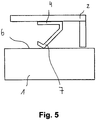
- Fig. 5 shows a rotary feedthrough with a sealing device 4, which is designed as a radial shaft seal with a metallic sealing lip 7.
- the sealing lip 7 is sealingly against the peripheral surface 6 of the adjusting shaft 1.
- Fig. 6 shows a rotary feedthrough with a sealing device 4, which has a mica seal 8.
- the mica seal 8 is located directly on the Adjusting shaft 1 in the region of the gap 3 at. The mica seal 8 is pressed by the adjusting shaft 1 and the bearing 2.
- Fig. 7 shows a rotary feedthrough in which two toothed wheels 9 with the interposition of a dense membrane 10 are engaged.
- the wheels 9 each have cams 9a, 9b which deform the flexible and soft diaphragms to engage opposing cams 9a, 9b.
- an adjusting shaft 1 can be actuated through a flexible membrane 10, the membrane 10 sealing two chambers 11, 12 against one another.
- Fig. 8 shows a rotary feedthrough in which the sealing device 4 has a contact pressure element 13, which exerts a pressing force in the radial direction and thereby unfolds a sealing effect in the axial direction.
- a first sealing surface 14 is non-rotatably connected to the adjusting shaft 1 and a second sealing surface 15 rotatably connected to the bearing 2.
- the gaps 3 are closed by axially pressed sealing elements 16a, 16b.
- Fig. 9 shows a rotary feedthrough with a sealing device 4, the microspheres 17 has.
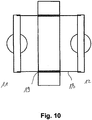
- Fig. 10 shows a rotary feedthrough in which a cylindrical membrane 18 is guided through a very narrow annular gap 19.
- Fig. 11 shows a rotary feedthrough in which a flat layer 20 is present wound up between a bearing 2 and an adjusting shaft 1. The winding produces very small gaps 3a, 3b.
- Fig. 12 shows a rotary feedthrough with a sealing device 4, which has two mica seals 8, which rest on both sides of two sealing surfaces of the adjusting shaft 1.
- Fig. 13 shows a rotary feedthrough in which two Verstellwellenenden 1a, 1b are connected to a lever 21 to which a sealing membrane 22 is fixed, in particular welded.
- Fig. 14 shows a rotary feedthrough in which two Verstellwellenenden 1 a, 1 b are hinged to a first ball 23 which is mounted in a concentrically arranged, larger, second ball 24.
- a ball shell gap 25 is generated, which can be formed very narrow and therefore produces a low leakage.
- Fig. 15 shows a rotary feedthrough, in which two Verstellwellenenden 1a, 1b with the interposition of a clamping diaphragm 26 engage each other such that a Verstellwellenende 1a, the other Verstellwellenende 1 b surrounds.
- Fig. 16 shows a rotary feedthrough in which two Verstellwellen 1 are connected by a loop-shaped wound belt 27 with each other to transmit rotation.
- the belt 27 passes through a wall 28 to form a narrow gap.
- Fig. 17 shows a rotary feedthrough with a bellows-type sealing device 29 which is mounted on a wall 28 tightly.
- the bellows-type sealing device 29 accommodates a linkage 30 which connects two adjusting shaft ends 1a, 1b to one another in a force-transmitting manner.
Landscapes
- Engineering & Computer Science (AREA)
- General Engineering & Computer Science (AREA)
- Mechanical Engineering (AREA)
- Sealing Using Fluids, Sealing Without Contact, And Removal Of Oil (AREA)
- Sealing Devices (AREA)
- Mechanical Sealing (AREA)
- Joints Allowing Movement (AREA)
Description
- Die Erfindung betrifft eine Drehdurchführung, umfassend eine Verstellwelle, welcher mit einer Betätigungseinrichtung kraftübertragend verbindbar ist.
- Aus der
WO 2005/008041 A1 ist eine Drehdurchführung der eingangs genannten Art bekannt, die zur Betätigung einer Wastegateklappe dient. In einem Turbolader werden Abgase verwendet, um ein Turbinenrad anzutreiben. Die Rotationsgeschwindigkeit des Turbinenrads kann kontrolliert werden, indem sogenannte Wastegateklappen geöffnet werden, so dass Abgase entweichen. Das Entweichen der Abgase führt zu einem Druckverlust innerhalb eines Raums, in dem das Turbinenrad rotiert. Die Temperatur der entweichenden Abgase kann über 1000°C betragen. Sie werden in einem weiteren Raum gesammelt, um einer Abgasbehandlung unterworfen zu werden. - Bei der Verwendung von Wastegateklappen ist stets dafür Sorge zu tragen, dass keine Abgase durch Spalte zwischen der Verstellwelle und dem Lager entweichen. Hierzu schlägt die
WO 2005/008041 A1 vor, an der kälteren Seite der Verstellwelle ein Federelement anzuordnen, welches Spaltbildung und Verschleiß einer keramischen Dichtung kompensiert. - Bei der gattungsbildenden Drehdurchführung ist nachteilig, dass eine keramische Dichtung zum Einsatz kommt, welche bei Vibrationen oder Kippbewegungen zur Spaltbildung neigt. Die keramische Dichtung liegt nämlich planparallel an einer ebenen Dichtfläche an, wobei die Dichtung bei auftretenden Vibrationen in ihrer Gesamtheit relativ zur Dichtfläche bewegt wird und dadurch Spalte erzeugt.
- Um dem zu begegnen, muss die keramische Dichtung durch das Federelement dauerhaft sehr stark gegen die Welle gepresst werden. Hiermit geht eine Abnutzung der Dichtung und eine Schwergängigkeit der Verstellwelle einher. Insbesondere muss bei der Fertigung der gattungsbildenden Drehdurchführung dafür Sorge getragen werden, dass die Federkraft stets ausreichend ist, um den jeweiligen Abnutzungsgrad der keramischen Dichtung und die Spaltbildung geeignet auszugleichen. Zudem werden bei einer einzelnen scheibenförmigen keramischen Dichtung sehr hohe Anforderungen an die Oberflächengüte und damit an die Fertigungsgenauigkeit gestellt, da selbst durch kleinste Spalte oder Unebenheiten sehr viel Gas entweichen kann.
- Der Erfindung liegt daher die Aufgabe zugrunde, eine Drehdurchführung der eingangs genannten Art derart auszugestalten und weiterzubilden, dass diese bei einfachem Aufbau eine dauerhaft hohe Dichtheit gegen Abgase zeigt.
- Die vorliegende Erfindung löst die zuvor genannte Aufgabe durch die Merkmale des Patentanspruchs 1.
- Danach ist eine Drehdurchführung der eingangs genannten Art durch eine Dichteinrichtung gekennzeichnet.
- Die Dichteinrichtung weist erfindungsgemäß eine Glimmerdichtung auf. Glimmer ist dauerhaft temperaturstabil und korrosionsstabil.
- Erfindungsgemäß ist erkannt worden, dass die Dichteinrichtung gemäß Anspruch 1 die Größe eines Spaltes minimiert, welcher zwischen einer Verstellwelle und einem Lager oder zwischen der Verstellwelle und weiteren Einrichtungen auftreten kann.
- Folglich ist die eingangs genannte Aufgabe gelöst.
- Die Dichteinrichtung kann selbstdichtend wirken und selbstständig Spalte verringern. Es besteht nämlich eine Proportionalität zwischen der Leckagerate (Liter/sec) und dem Produkt aus der dritten Potenz der Spaltbreite und der Druckdifferenz zwischen den gegeneinander abzudichtenden Räumen. Eine Verkleinerung der Spaltbreite reduziert daher die Leckagerate sehr viel mehr, als eine Verminderung der Druckdifferenz.
- Eine Dichteinrichtung könnte einen Federring aufweisen, welcher in radialer Richtung eine Presskraft ausübt und dadurch eine Dichtwirkung in axialer Richtung entfaltet. Somit ist auf engem Bauraum eine Kraftumlenkung ermöglicht.
- Die Dichteinrichtung könnte eine Lamellendichtung aufweisen. Die Lamellen liegen an der Umfangsfläche der Verstellwelle dichtend an und sind in axialer Richtung verpressbar.
- Die Dichteinrichtung könnte als Radialwellendichtring mit einer metallischen Dichtlippe ausgestaltet sein. Die Dichtlippe kann an der Umfangsfläche der Verstellwelle dichtend anliegen. Metallische Dichtungen sind äußerst temperaturstabil.
- Erfindungsgemäß weist die Dichteinrichtung ein Anpresselement auf, welches in radialer Richtung eine Presskraft ausübt und dadurch eine Dichtwirkung in axialer Richtung entfaltet. Spalte können hierbei durch axial verpresste Abdichtelemente verschlossen werden.
- Die Dichteinrichtung könnte Mikrokugeln aufweisen. Hierdurch wird eine leichtgängige Verstellwelle unter Ausbildung eine Labyrinthdichtung realisiert. Eine Dichteinrichtung könnte zwei Glimmerdichtungen aufweisen. Hierdurch ist eine beidseitige Abdichtung der Verstellwelle möglich.
- Zwei Verstellwellenenden könnten mit einem Hebel verbunden sein, an dem eine abdichtende Membran festgelegt, insbesondere angeschweißt ist. Hierdurch werden abzudichtende Räume gegeneinander zuverlässig hermetisch abgedichtet.
- Zwei Verstellwellenenden könnten an einer ersten Kugel angelenkt sein, welcher in einer konzentrisch angeordneten, größeren zweiten Kugel gelagert ist. Hierbei wird ein Kugelschalenspalt erzeugt, der sehr eng ausgebildet sein kann und daher eine geringe Leckage erzeugt.
- Zwei Verstellwellenenden könnten unter Zwischenlage einer Klemmmembran derart ineinander greifen, dass ein Verstellwellenende das andere Verstellwellenende umgibt. Hierdurch ist eine platzsparende koaxiale Anordnung der Verstellwellenenden ermöglicht.
- Die hier beschriebene Drehdurchführung wird zur Betätigung von Wastegateklappen verwendet. Hierdurch ist eine sehr dichte und stabile Drehdurchführung in einem Turbolader eines Kraftfahrzeugs einsetzbar.
- Die Drehdurchführung kann zur Betätigung von Abgasrückführungsklappen oder Abgasklappen verwendet werden. Die Drehdurchführung kann zur Verstellung von variablen Turbinengeometrien (VTG) verwendet werden. Die Drehdurchführung kann in PKWs, LKWs, oder im Kraftwerksbereich verwendet werden.
- Es gibt nun verschiedene Möglichkeiten, die Lehre der vorliegenden Erfindung auf vorteilhafte Weise auszugestalten und weiterzubilden. Dazu ist einerseits auf die nachgeordneten Ansprüche, andererseits auf die nachfolgende Erläuterung bevorzugter Ausführungsbeispiele der Erfindung anhand der Zeichnung zu verweisen.
- Mit der Erläuterung der bevorzugten Ausführungsbeispiele der Erfindung anhand der Zeichnung werden auch im Allgemeinen bevorzugte Ausgestaltungen und Weiterbildungen der Lehre erläutert.
- In der Zeichnung zeigen
- Fig. 1
- eine Drehdurchführung, bei welcher die Dichteinrichtung einen Federring aufweist, welcher in radialer Richtung eine Presskraft ausübt und dadurch eine Dichtwirkung in axialer Richtung entfaltet,
- Fig. 2
- eine nicht dem Anspruch 1 unterfallende Drehdurchführung mit einer gekammerten Graphitdichtung,
- Fig. 3
- eine nicht dem Anspruch 1 unterfallende Drehdurchführung mit einer einseitig offenen gekammerten Graphitdichtung,
- Fig. 4
- eine nicht dem Anspruch 1 unterfallende Drehdurchführung mit einer Lamellendichtung,
- Fig. 5
- eine nicht dem Anspruch 1 unterfallende Drehdurchführung mit einer Dichteinrichtung, die als Radialwellendichtring mit einer metallischen Dichtlippe ausgestaltet ist,
- Fig. 6
- eine Drehdurchführung mit einer Dichteinrichtung, die Glimmer aufweist,
- Fig. 7
- eine nicht dem Anspruch 1 unterfallende Drehdurchführung, bei welcher zwei gezahnte Räder unter Zwischenlage einer dichten Membran in Eingriff stehen,
- Fig. 8
- eine Drehdurchführung bei welcher die Dichteinrichtung ein Anpresselement aufweist, welches in radialer Richtung eine Presskraft ausübt und dadurch eine Dichtwirkung in axialer Richtung entfaltet,
- Fig. 9
- eine nicht dem Anspruch 1 unterfallende Drehdurchführung mit einer Dichteinrichtung, die Mikrokugeln aufweist,
- Fig. 10
- eine nicht dem Anspruch 1 unterfallende Drehdurchführung, bei welcher eine Membran durch einen sehr engen Ringspalt geführt ist,
- Fig. 11
- eine nicht dem Anspruch 1 unterfallende Drehdurchführung, bei welcher eine flächige Lage zwischen einem Lager und einer Verstellwelle aufgewickelt vorliegt,
- Fig. 12
- eine nicht dem Anspruch 1 unterfallende Drehdurchführung mit einer Dichteinrichtung, die Glimmerdichtungen aufweist, die beidseitig an der Verstellwelle anliegen,
- Fig. 13
- eine nicht dem Anspruch 1 unterfallende Drehdurchführung, bei der zwei Verstellwellenenden mit einem Hebel verbunden sind, an dem eine abdichtende Membran festgelegt, insbesondere angeschweisst ist,
- Fig. 14
- eine nicht dem Anspruch 1 unterfallende Drehdurchführung, bei welcher zwei Verstellwellenenden an einer Kugel angelenkt sind, welche in einer konzentrisch angeordneten, größeren Kugel gelagert ist,
- Fig. 15
- eine nicht dem Anspruch 1 unterfallende Drehdurchführung, bei welcher zwei Verstellwellenenden unter Zwischenlage einer Membran derart ineinander greifen, dass ein Verstellwellenende das andere umgibt,
- Fig. 16
- eine nicht dem Anspruch 1 unterfallende Drehdurchführung, bei welcher zwei Verstellwellen durch einen schlaufenförmig gewundenen Riemen miteinander drehübertragend verbunden sind, und
- Fig. 17
- eine nicht dem Anspruch 1 unterfallende Drehdurchführung mit einer faltenbalgartigen Dichteinrichtung
-
Fig. 1 zeigt eine Drehdurchführung, umfassend eine Verstellwelle 1 welche mit einer nicht gezeigten Betätigungseinreichtung kraftübertragend verbunden ist, wobei die Verstellwelle 1 in einem Lager 2 gelagert ist und wobei zwischen dem Lager 2 und der Verstellwelle 1 mindestens ein abzudichtender Spalt 3 ausgebildet ist. Eine Dichteinrichtung 4 weist einen Federring 5 auf, welcher in radialer Richtung eine Presskraft ausübt und dadurch eine Dichtwirkung in axialer Richtung entfaltet. Der Federring 5 presst die konisch ausgebildeten Dichtelemente 5a, 5b in axialer Richtung gegen Dichtflächen bzw. ein weiteres Dichtelement 5c, indem er in radialer Richtung Kraft ausübt. Das weitere Dichtelement 5c ist aus Keramik oder einem Gleitwerkstoff gefertigt und liegt unmittelbar an der Verstellwelle 1 an. Das weitere Dichtelement 5c kann auch als Beschichtung ausgebildet sein. -
Fig. 2 zeigt eine Drehdurchführung mit einer Dichteinrichtung 4, die als gekammerte Graphitdichtung ausgestaltet ist. Die Graphitdichtung besteht aus Graphit, der von einer Metallfolie 4a umgeben ist. Die Graphitdichtung könnte auch als gewickelte Graphitdichtung ausgebildet sein. Das weitere Dichtelement 5c ist aus einem Gleitwerkstoff gefertigt, kann jedoch auch als Beschichtung ausgebildet sein. -
Fig. 3 zeigt eine Drehdurchführung mit einer einseitig offenen gekammerten Graphitdichtung. Die Metallfolie 4a ist am Spalt 3 unterbrochen, so dass der Graphit unmittelbar an der Verstellwelle anliegen kann. -
Fig. 4 zeigt eine Drehdurchführung mit einer Lamellendichtung. Die Dichteinrichtung 4 weist Lamellen 4b auf, die in axialer Abfolge angeordnet sind. Die Lamellen 4b liegen an der Umfangsfläche 6 der Verstellwelle 1 dichtend an. -
Fig. 5 zeigt eine Drehdurchführung mit einer Dichteinrichtung 4, die als Radialwellendichtring mit einer metallischen Dichtlippe 7 ausgestaltet ist. Die Dichtlippe 7 liegt an der Umfangsfläche 6 der Verstellwelle 1 dichtend an. -
Fig. 6 zeigt eine Drehdurchführung mit einer Dichteinrichtung 4, die eine Glimmerdichtung 8 aufweist. Die Glimmerdichtung 8 liegt unmittelbar an der Verstellwelle 1 im Bereich des Spalts 3 an. Die Glimmerdichtung 8 wird durch die Verstellwelle 1 und das Lager 2 verpresst. -
Fig. 7 zeigt eine Drehdurchführung, bei welcher zwei gezahnte Räder 9 unter Zwischenlage einer dichten Membran 10 in Eingriff stehen. Die Räder 9 weisen jeweils Nocken 9a, 9b auf, die die flexible und weiche Membran deformieren, um mit gegenüberliegenden Nocken 9a, 9b in Eingriff zu treten. Hierdurch kann eine Verstellwelle 1 durch eine flexible Membran 10 hindurch betätigt werden, wobei die Membran 10 zwei Räume 11,12 gegeneinander abdichtet. -
Fig. 8 zeigt eine Drehdurchführung bei welcher die Dichteinrichtung 4 ein Anpresselement 13 aufweist, welches in radialer Richtung eine Presskraft ausübt und dadurch eine Dichtwirkung in axialer Richtung entfaltet. Eine erste Dichtfläche 14 ist drehfest mit der Verstellwelle 1 und eine zweite Dichtfläche 15 drehfest mit dem Lager 2 verbunden. Die Spalte 3 werden durch axial verpresste Abdichtelemente 16a, 16b verschlossen. -
Fig. 9 zeigt eine Drehdurchführung mit einer Dichteinrichtung 4, die Mikrokugeln 17 aufweist. -
Fig. 10 zeigt eine Drehdurchführung, bei welcher eine zylindrische Membran 18 durch einen sehr engen Ringspalt 19 geführt ist. -
Fig. 11 zeigt eine Drehdurchführung, bei welcher eine flächige Lage 20 zwischen einem Lager 2 und einer Verstellwelle 1 aufgewickelt vorliegt. Durch die Wicklung werden sehr kleine Spalte 3a, 3b erzeugt. -
Fig. 12 zeigt eine Drehdurchführung mit einer Dichteinrichtung 4, die zwei Glimmerdichtungen 8 aufweist, die beidseitig an zwei Dichtflächen der Verstellwelle 1 anliegen. -
Fig. 13 zeigt eine Drehdurchführung, bei der zwei Verstellwellenenden 1a, 1b mit einem Hebel 21 verbunden sind, an dem eine abdichtende Membran 22 festgelegt, insbesondere angeschweisst ist. Hierdurch werden die abzudichtenden Räume 11,12 gegeneinander zuverlässig abgedichtet. -
Fig. 14 zeigt eine Drehdurchführung, bei welcher zwei Verstellwellenenden 1a, 1b an einer ersten Kugel 23 angelenkt sind, welche in einer konzentrisch angeordneten, größeren, zweiten Kugel 24 gelagert ist. Hierbei wird ein Kugelschalenspalt 25 erzeugt, der sehr eng ausgebildet sein kann und daher eine geringe Leckage erzeugt. -
Fig. 15 zeigt eine Drehdurchführung, bei welcher zwei Verstellwellenenden 1a, 1b unter Zwischenlage einer Klemmmembran 26 derart ineinander greifen, dass ein Verstellwellenende 1a, das andere Verstellwellenende 1 b umgibt. -
Fig. 16 zeigt eine Drehdurchführung, bei welcher zwei Verstellwellen 1 durch einen schlaufenförmig gewundenen Riemen 27 miteinander drehübertragend verbunden sind. Der Riemen 27 durchgreift eine Wand 28 unter Ausbildung eines engen Spalts 3. -
Fig. 17 zeigt eine Drehdurchführung mit einer faltenbalgartigen Dichteinrichtung 29, die an einer Wand 28 dicht angebracht ist. Die faltenbalgartige Dichteinrichtung 29 nimmt ein Gestänge 30 auf, welches zwei Verstellwellenenden 1a, 1b kraftübertragend miteinander verbindet. - Hinsichtlich weiterer vorteilhafter Ausgestaltungen und Weiterbildungen der Erfindungsgemäßen Lehre wird einerseits auf den allgemeinen Teil der Beschreibung und andererseits auf die beigefügten Patentansprüche verwiesen.
- Abschließend sei ganz besonders hervorgehoben, dass die zuvor ausgewählten Ausführungsbeispiele lediglich zur Erörterung der erfindungsgemäßen Lehre dienen, diese jedoch nicht auf diese Ausführungsbeispiele einschränkt.
Claims (3)
- Drehdurchführung, für eine Wastegateklappe eines Turboladers, umfassend eine Verstellwelle (1), welche mit einer Betätigungseinrichtung kraftübertragend verbunden ist, mit einer Dichteinrichtung (4), die gegen Abgase abdichtet und, dadurch gekennzeichnet, dass die Dichteinrichtung (4) als Glimmerdichtung (8) ausgestaltet ist, und dass die Dichteinrichtung (4) ein Anpresselement (13) aufweist, welches in radialer Richtung eine Presskraft ausübt und dadurch eine Dichtwirkung in axialer Richtung entfaltet.
- Drehdurchführung nach Anspruch 1, dadurch gekennzeichnet, dass die Dichteinrichtung (4) einen Federring (5) aufweist, der in radialer Richtung eine Presskraft ausübt und dadurch eine Dichtwirkung in axialer Richtung entfaltet.
- Drehdurchführung nach Anspruch 1, dadurch gekennzeichnet, dass die Dichteinrichtung (4) zwei Glimmerdichtungen (8) aufweist.
Applications Claiming Priority (2)
| Application Number | Priority Date | Filing Date | Title |
|---|---|---|---|
| DE200910022109 DE102009022109A1 (de) | 2009-05-20 | 2009-05-20 | Drehdurchführung mit geringer Gasdurchlässigkeit |
| PCT/EP2010/002732 WO2010133293A2 (de) | 2009-05-20 | 2010-05-04 | Drehdurchführung mit geringer gasdurchlässigkeit |
Publications (2)
| Publication Number | Publication Date |
|---|---|
| EP2433036A2 EP2433036A2 (de) | 2012-03-28 |
| EP2433036B1 true EP2433036B1 (de) | 2016-12-28 |
Family
ID=42671775
Family Applications (1)
| Application Number | Title | Priority Date | Filing Date |
|---|---|---|---|
| EP10721670.7A Active EP2433036B1 (de) | 2009-05-20 | 2010-05-04 | Drehdurchführung mit geringer gasdurchlässigkeit |
Country Status (3)
| Country | Link |
|---|---|
| EP (1) | EP2433036B1 (de) |
| DE (1) | DE102009022109A1 (de) |
| WO (1) | WO2010133293A2 (de) |
Families Citing this family (3)
| Publication number | Priority date | Publication date | Assignee | Title |
|---|---|---|---|---|
| DE202012004719U1 (de) * | 2012-05-11 | 2012-05-29 | Borgwarner Inc. | Regelklappenanordnung eines Abgasturboladers |
| US11236667B2 (en) | 2016-07-27 | 2022-02-01 | Vitesco Technologies GmbH | Flap device for opening and closing a wastegate channel in a turbine housing of a turbocharger, turbocharger, and method for production |
| DE102018213211A1 (de) | 2018-08-07 | 2020-02-13 | Robert Bosch Gmbh | Dichtelement |
Citations (1)
| Publication number | Priority date | Publication date | Assignee | Title |
|---|---|---|---|---|
| DE2526182B1 (de) * | 1975-06-12 | 1976-09-02 | Sigri Elektrographit Gmbh | Verfahren zum herstellen eines dichtungsrings |
Family Cites Families (5)
| Publication number | Priority date | Publication date | Assignee | Title |
|---|---|---|---|---|
| GB899719A (en) * | 1959-08-12 | 1962-06-27 | Sulzer Ag | Shaft seal assemblies |
| US3460842A (en) * | 1965-12-28 | 1969-08-12 | Fmc Corp | Multidisc shaft seal |
| JPS556067A (en) * | 1978-06-30 | 1980-01-17 | Arai Pump Mfg Co Ltd | Slant face seal |
| DE3432852C1 (de) * | 1984-09-07 | 1985-10-31 | Goetze Ag, 5093 Burscheid | Gleitring für Gleitringdichtung mit insbesondere wechselnder Reibbelastung unter gleichzeitiger Druckbelastung |
| US7644583B2 (en) | 2003-07-11 | 2010-01-12 | Malcolm George Leavesley | Turbocharger apparatus having an exhaust gas sealing system for preventing gas leakage from the turbocharger apparatus |
-
2009
- 2009-05-20 DE DE200910022109 patent/DE102009022109A1/de not_active Withdrawn
-
2010
- 2010-05-04 EP EP10721670.7A patent/EP2433036B1/de active Active
- 2010-05-04 WO PCT/EP2010/002732 patent/WO2010133293A2/de not_active Ceased
Patent Citations (1)
| Publication number | Priority date | Publication date | Assignee | Title |
|---|---|---|---|---|
| DE2526182B1 (de) * | 1975-06-12 | 1976-09-02 | Sigri Elektrographit Gmbh | Verfahren zum herstellen eines dichtungsrings |
Also Published As
| Publication number | Publication date |
|---|---|
| WO2010133293A3 (de) | 2011-04-14 |
| DE102009022109A1 (de) | 2010-11-25 |
| WO2010133293A2 (de) | 2010-11-25 |
| EP2433036A2 (de) | 2012-03-28 |
Similar Documents
| Publication | Publication Date | Title |
|---|---|---|
| DE112014002468T5 (de) | Leichtgängiges Dichtungsverfahren für ein Temperaturregelventil | |
| EP2850351B1 (de) | Ventil und membran für ein ventil | |
| DE102012009095A1 (de) | Wellendichtung mit Lamellen | |
| DE102010021431A1 (de) | Variables Flanschanquetschwerkzeug | |
| WO2005024259A1 (de) | Gleichlaufgelenk mit dichtungsanordnung | |
| DE102015220333A1 (de) | Vorrichtung zur Einstellung eines Spaltes zwischen dem Gehäuse eines Laufrades und dem Laufrad in einem Radialverdichter und eine Turbomaschine | |
| DE102016210576A1 (de) | Kugelrampenstellglied | |
| DE102019131610A1 (de) | Drosselventil | |
| DE102011075791A1 (de) | Verbindungsvorrichtung für einen fahrzeugsitz | |
| EP2433036A2 (de) | Drehdurchführung mit geringer gasdurchlässigkeit | |
| DE4244573C2 (de) | Pneumatischer Membranstellantrieb | |
| WO2020001805A1 (de) | Abgasturbolader mit zentriertem leitschaufelring | |
| WO2010054884A2 (de) | Welleneinrichtung mit einer dichtungsvorrichtung | |
| DE102009018373A1 (de) | Zweilippige Gummidichtung mit Versteifung | |
| EP3171063A1 (de) | Vakuumeckventil mit kulissenantrieb | |
| DE102011083660A1 (de) | Fluidkanalventil | |
| DE102012003709A1 (de) | Abgasführungsanordnung für einen aufladbaren oder aufgeladenen Verbrennungsmotor | |
| EP1500853B1 (de) | Dichtung mit variablem Innendurchmesser | |
| WO2014019976A1 (de) | Segmentplattenventil und dampfturbinenanordnung | |
| EP2233729B1 (de) | Klappenvorrichtung für eine Verbrennungskraftmaschine | |
| DE102013225361A1 (de) | Aktor zur Betätigung einer Kupplung | |
| EP1602846B1 (de) | Kupplungsanordnung | |
| EP3867505B1 (de) | Abgasturbine eines abgasturboladers mit einer abgedichteten wastegate-ventileinrichtung sowie abgasturbolader | |
| WO2007048163A1 (de) | Quetschventil | |
| DE102007015073A1 (de) | Rollbalg für Gelenkwellen von Kraftfahrzeugen |
Legal Events
| Date | Code | Title | Description |
|---|---|---|---|
| PUAI | Public reference made under article 153(3) epc to a published international application that has entered the european phase |
Free format text: ORIGINAL CODE: 0009012 |
|
| 17P | Request for examination filed |
Effective date: 20111214 |
|
| AK | Designated contracting states |
Kind code of ref document: A2 Designated state(s): AL AT BE BG CH CY CZ DE DK EE ES FI FR GB GR HR HU IE IS IT LI LT LU LV MC MK MT NL NO PL PT RO SE SI SK SM TR |
|
| DAX | Request for extension of the european patent (deleted) | ||
| RAP1 | Party data changed (applicant data changed or rights of an application transferred) |
Owner name: ELRINGKLINGER AG |
|
| 17Q | First examination report despatched |
Effective date: 20131014 |
|
| REG | Reference to a national code |
Ref country code: DE Ref legal event code: R079 Ref document number: 502010012963 Country of ref document: DE Free format text: PREVIOUS MAIN CLASS: F16J0015320000 Ipc: F02B0037180000 |
|
| GRAP | Despatch of communication of intention to grant a patent |
Free format text: ORIGINAL CODE: EPIDOSNIGR1 |
|
| RIC1 | Information provided on ipc code assigned before grant |
Ipc: F16J 15/52 20060101ALI20160705BHEP Ipc: F02B 37/18 20060101AFI20160705BHEP Ipc: F16J 15/34 20060101ALI20160705BHEP Ipc: F16J 15/3204 20160101ALI20160705BHEP Ipc: F16J 15/3228 20160101ALI20160705BHEP Ipc: F16J 15/3284 20160101ALI20160705BHEP |
|
| INTG | Intention to grant announced |
Effective date: 20160720 |
|
| GRAS | Grant fee paid |
Free format text: ORIGINAL CODE: EPIDOSNIGR3 |
|
| GRAA | (expected) grant |
Free format text: ORIGINAL CODE: 0009210 |
|
| AK | Designated contracting states |
Kind code of ref document: B1 Designated state(s): AL AT BE BG CH CY CZ DE DK EE ES FI FR GB GR HR HU IE IS IT LI LT LU LV MC MK MT NL NO PL PT RO SE SI SK SM TR |
|
| REG | Reference to a national code |
Ref country code: GB Ref legal event code: FG4D Free format text: NOT ENGLISH |
|
| REG | Reference to a national code |
Ref country code: CH Ref legal event code: EP |
|
| REG | Reference to a national code |
Ref country code: DE Ref legal event code: R082 Ref document number: 502010012963 Country of ref document: DE Representative=s name: HOEGER, STELLRECHT & PARTNER PATENTANWAELTE MB, DE |
|
| REG | Reference to a national code |
Ref country code: AT Ref legal event code: REF Ref document number: 857505 Country of ref document: AT Kind code of ref document: T Effective date: 20170115 |
|
| REG | Reference to a national code |
Ref country code: IE Ref legal event code: FG4D Free format text: LANGUAGE OF EP DOCUMENT: GERMAN |
|
| REG | Reference to a national code |
Ref country code: DE Ref legal event code: R096 Ref document number: 502010012963 Country of ref document: DE |
|
| PG25 | Lapsed in a contracting state [announced via postgrant information from national office to epo] |
Ref country code: LV Free format text: LAPSE BECAUSE OF FAILURE TO SUBMIT A TRANSLATION OF THE DESCRIPTION OR TO PAY THE FEE WITHIN THE PRESCRIBED TIME-LIMIT Effective date: 20161228 |
|
| REG | Reference to a national code |
Ref country code: LT Ref legal event code: MG4D |
|
| PG25 | Lapsed in a contracting state [announced via postgrant information from national office to epo] |
Ref country code: GR Free format text: LAPSE BECAUSE OF FAILURE TO SUBMIT A TRANSLATION OF THE DESCRIPTION OR TO PAY THE FEE WITHIN THE PRESCRIBED TIME-LIMIT Effective date: 20170329 Ref country code: NO Free format text: LAPSE BECAUSE OF FAILURE TO SUBMIT A TRANSLATION OF THE DESCRIPTION OR TO PAY THE FEE WITHIN THE PRESCRIBED TIME-LIMIT Effective date: 20170328 Ref country code: LT Free format text: LAPSE BECAUSE OF FAILURE TO SUBMIT A TRANSLATION OF THE DESCRIPTION OR TO PAY THE FEE WITHIN THE PRESCRIBED TIME-LIMIT Effective date: 20161228 Ref country code: SE Free format text: LAPSE BECAUSE OF FAILURE TO SUBMIT A TRANSLATION OF THE DESCRIPTION OR TO PAY THE FEE WITHIN THE PRESCRIBED TIME-LIMIT Effective date: 20161228 |
|
| REG | Reference to a national code |
Ref country code: NL Ref legal event code: MP Effective date: 20161228 |
|
| PG25 | Lapsed in a contracting state [announced via postgrant information from national office to epo] |
Ref country code: FI Free format text: LAPSE BECAUSE OF FAILURE TO SUBMIT A TRANSLATION OF THE DESCRIPTION OR TO PAY THE FEE WITHIN THE PRESCRIBED TIME-LIMIT Effective date: 20161228 Ref country code: HR Free format text: LAPSE BECAUSE OF FAILURE TO SUBMIT A TRANSLATION OF THE DESCRIPTION OR TO PAY THE FEE WITHIN THE PRESCRIBED TIME-LIMIT Effective date: 20161228 |
|
| PG25 | Lapsed in a contracting state [announced via postgrant information from national office to epo] |
Ref country code: NL Free format text: LAPSE BECAUSE OF FAILURE TO SUBMIT A TRANSLATION OF THE DESCRIPTION OR TO PAY THE FEE WITHIN THE PRESCRIBED TIME-LIMIT Effective date: 20161228 |
|
| PG25 | Lapsed in a contracting state [announced via postgrant information from national office to epo] |
Ref country code: EE Free format text: LAPSE BECAUSE OF FAILURE TO SUBMIT A TRANSLATION OF THE DESCRIPTION OR TO PAY THE FEE WITHIN THE PRESCRIBED TIME-LIMIT Effective date: 20161228 Ref country code: CZ Free format text: LAPSE BECAUSE OF FAILURE TO SUBMIT A TRANSLATION OF THE DESCRIPTION OR TO PAY THE FEE WITHIN THE PRESCRIBED TIME-LIMIT Effective date: 20161228 Ref country code: RO Free format text: LAPSE BECAUSE OF FAILURE TO SUBMIT A TRANSLATION OF THE DESCRIPTION OR TO PAY THE FEE WITHIN THE PRESCRIBED TIME-LIMIT Effective date: 20161228 Ref country code: IS Free format text: LAPSE BECAUSE OF FAILURE TO SUBMIT A TRANSLATION OF THE DESCRIPTION OR TO PAY THE FEE WITHIN THE PRESCRIBED TIME-LIMIT Effective date: 20170428 Ref country code: SK Free format text: LAPSE BECAUSE OF FAILURE TO SUBMIT A TRANSLATION OF THE DESCRIPTION OR TO PAY THE FEE WITHIN THE PRESCRIBED TIME-LIMIT Effective date: 20161228 |
|
| PG25 | Lapsed in a contracting state [announced via postgrant information from national office to epo] |
Ref country code: SM Free format text: LAPSE BECAUSE OF FAILURE TO SUBMIT A TRANSLATION OF THE DESCRIPTION OR TO PAY THE FEE WITHIN THE PRESCRIBED TIME-LIMIT Effective date: 20161228 Ref country code: PL Free format text: LAPSE BECAUSE OF FAILURE TO SUBMIT A TRANSLATION OF THE DESCRIPTION OR TO PAY THE FEE WITHIN THE PRESCRIBED TIME-LIMIT Effective date: 20161228 Ref country code: PT Free format text: LAPSE BECAUSE OF FAILURE TO SUBMIT A TRANSLATION OF THE DESCRIPTION OR TO PAY THE FEE WITHIN THE PRESCRIBED TIME-LIMIT Effective date: 20170428 Ref country code: BG Free format text: LAPSE BECAUSE OF FAILURE TO SUBMIT A TRANSLATION OF THE DESCRIPTION OR TO PAY THE FEE WITHIN THE PRESCRIBED TIME-LIMIT Effective date: 20170328 Ref country code: ES Free format text: LAPSE BECAUSE OF FAILURE TO SUBMIT A TRANSLATION OF THE DESCRIPTION OR TO PAY THE FEE WITHIN THE PRESCRIBED TIME-LIMIT Effective date: 20161228 Ref country code: IT Free format text: LAPSE BECAUSE OF FAILURE TO SUBMIT A TRANSLATION OF THE DESCRIPTION OR TO PAY THE FEE WITHIN THE PRESCRIBED TIME-LIMIT Effective date: 20161228 Ref country code: LU Free format text: LAPSE BECAUSE OF NON-PAYMENT OF DUE FEES Effective date: 20170531 |
|
| REG | Reference to a national code |
Ref country code: DE Ref legal event code: R097 Ref document number: 502010012963 Country of ref document: DE |
|
| PLBE | No opposition filed within time limit |
Free format text: ORIGINAL CODE: 0009261 |
|
| STAA | Information on the status of an ep patent application or granted ep patent |
Free format text: STATUS: NO OPPOSITION FILED WITHIN TIME LIMIT |
|
| PG25 | Lapsed in a contracting state [announced via postgrant information from national office to epo] |
Ref country code: DK Free format text: LAPSE BECAUSE OF FAILURE TO SUBMIT A TRANSLATION OF THE DESCRIPTION OR TO PAY THE FEE WITHIN THE PRESCRIBED TIME-LIMIT Effective date: 20161228 |
|
| 26N | No opposition filed |
Effective date: 20170929 |
|
| REG | Reference to a national code |
Ref country code: CH Ref legal event code: PL |
|
| GBPC | Gb: european patent ceased through non-payment of renewal fee |
Effective date: 20170504 |
|
| PG25 | Lapsed in a contracting state [announced via postgrant information from national office to epo] |
Ref country code: MC Free format text: LAPSE BECAUSE OF FAILURE TO SUBMIT A TRANSLATION OF THE DESCRIPTION OR TO PAY THE FEE WITHIN THE PRESCRIBED TIME-LIMIT Effective date: 20161228 |
|
| REG | Reference to a national code |
Ref country code: IE Ref legal event code: MM4A |
|
| PG25 | Lapsed in a contracting state [announced via postgrant information from national office to epo] |
Ref country code: SI Free format text: LAPSE BECAUSE OF FAILURE TO SUBMIT A TRANSLATION OF THE DESCRIPTION OR TO PAY THE FEE WITHIN THE PRESCRIBED TIME-LIMIT Effective date: 20161228 Ref country code: LI Free format text: LAPSE BECAUSE OF NON-PAYMENT OF DUE FEES Effective date: 20170531 Ref country code: CH Free format text: LAPSE BECAUSE OF NON-PAYMENT OF DUE FEES Effective date: 20170531 |
|
| REG | Reference to a national code |
Ref country code: FR Ref legal event code: ST Effective date: 20180131 |
|
| PG25 | Lapsed in a contracting state [announced via postgrant information from national office to epo] |
Ref country code: LU Free format text: LAPSE BECAUSE OF NON-PAYMENT OF DUE FEES Effective date: 20170504 |
|
| REG | Reference to a national code |
Ref country code: BE Ref legal event code: MM Effective date: 20170531 |
|
| PG25 | Lapsed in a contracting state [announced via postgrant information from national office to epo] |
Ref country code: IE Free format text: LAPSE BECAUSE OF NON-PAYMENT OF DUE FEES Effective date: 20170504 Ref country code: GB Free format text: LAPSE BECAUSE OF NON-PAYMENT OF DUE FEES Effective date: 20170504 |
|
| PG25 | Lapsed in a contracting state [announced via postgrant information from national office to epo] |
Ref country code: FR Free format text: LAPSE BECAUSE OF NON-PAYMENT OF DUE FEES Effective date: 20170531 |
|
| REG | Reference to a national code |
Ref country code: AT Ref legal event code: MM01 Ref document number: 857505 Country of ref document: AT Kind code of ref document: T Effective date: 20170504 |
|
| PG25 | Lapsed in a contracting state [announced via postgrant information from national office to epo] |
Ref country code: AT Free format text: LAPSE BECAUSE OF NON-PAYMENT OF DUE FEES Effective date: 20170504 Ref country code: BE Free format text: LAPSE BECAUSE OF NON-PAYMENT OF DUE FEES Effective date: 20170531 |
|
| PG25 | Lapsed in a contracting state [announced via postgrant information from national office to epo] |
Ref country code: MT Free format text: LAPSE BECAUSE OF FAILURE TO SUBMIT A TRANSLATION OF THE DESCRIPTION OR TO PAY THE FEE WITHIN THE PRESCRIBED TIME-LIMIT Effective date: 20161228 |
|
| PG25 | Lapsed in a contracting state [announced via postgrant information from national office to epo] |
Ref country code: HU Free format text: LAPSE BECAUSE OF FAILURE TO SUBMIT A TRANSLATION OF THE DESCRIPTION OR TO PAY THE FEE WITHIN THE PRESCRIBED TIME-LIMIT; INVALID AB INITIO Effective date: 20100504 |
|
| PG25 | Lapsed in a contracting state [announced via postgrant information from national office to epo] |
Ref country code: CY Free format text: LAPSE BECAUSE OF NON-PAYMENT OF DUE FEES Effective date: 20161228 |
|
| PG25 | Lapsed in a contracting state [announced via postgrant information from national office to epo] |
Ref country code: MK Free format text: LAPSE BECAUSE OF FAILURE TO SUBMIT A TRANSLATION OF THE DESCRIPTION OR TO PAY THE FEE WITHIN THE PRESCRIBED TIME-LIMIT Effective date: 20161228 |
|
| PG25 | Lapsed in a contracting state [announced via postgrant information from national office to epo] |
Ref country code: TR Free format text: LAPSE BECAUSE OF FAILURE TO SUBMIT A TRANSLATION OF THE DESCRIPTION OR TO PAY THE FEE WITHIN THE PRESCRIBED TIME-LIMIT Effective date: 20161228 |
|
| PG25 | Lapsed in a contracting state [announced via postgrant information from national office to epo] |
Ref country code: AL Free format text: LAPSE BECAUSE OF FAILURE TO SUBMIT A TRANSLATION OF THE DESCRIPTION OR TO PAY THE FEE WITHIN THE PRESCRIBED TIME-LIMIT Effective date: 20161228 |
|
| P01 | Opt-out of the competence of the unified patent court (upc) registered |
Effective date: 20230512 |
|
| PGFP | Annual fee paid to national office [announced via postgrant information from national office to epo] |
Ref country code: DE Payment date: 20250519 Year of fee payment: 16 |