EP2432683B1 - Support of propeller unit for a vessel - Google Patents
Support of propeller unit for a vessel Download PDFInfo
- Publication number
- EP2432683B1 EP2432683B1 EP10732479.0A EP10732479A EP2432683B1 EP 2432683 B1 EP2432683 B1 EP 2432683B1 EP 10732479 A EP10732479 A EP 10732479A EP 2432683 B1 EP2432683 B1 EP 2432683B1
- Authority
- EP
- European Patent Office
- Prior art keywords
- permanent magnets
- rotor housing
- external
- stationary casing
- rotatable rotor
- Prior art date
- Legal status (The legal status is an assumption and is not a legal conclusion. Google has not performed a legal analysis and makes no representation as to the accuracy of the status listed.)
- Active
Links
Images

Classifications
-
- B—PERFORMING OPERATIONS; TRANSPORTING
- B63—SHIPS OR OTHER WATERBORNE VESSELS; RELATED EQUIPMENT
- B63H—MARINE PROPULSION OR STEERING
- B63H23/00—Transmitting power from propulsion power plant to propulsive elements
- B63H23/22—Transmitting power from propulsion power plant to propulsive elements with non-mechanical gearing
- B63H23/24—Transmitting power from propulsion power plant to propulsive elements with non-mechanical gearing electric
-
- F—MECHANICAL ENGINEERING; LIGHTING; HEATING; WEAPONS; BLASTING
- F16—ENGINEERING ELEMENTS AND UNITS; GENERAL MEASURES FOR PRODUCING AND MAINTAINING EFFECTIVE FUNCTIONING OF MACHINES OR INSTALLATIONS; THERMAL INSULATION IN GENERAL
- F16C—SHAFTS; FLEXIBLE SHAFTS; ELEMENTS OR CRANKSHAFT MECHANISMS; ROTARY BODIES OTHER THAN GEARING ELEMENTS; BEARINGS
- F16C39/00—Relieving load on bearings
- F16C39/06—Relieving load on bearings using magnetic means
- F16C39/063—Permanent magnets
-
- H—ELECTRICITY
- H02—GENERATION; CONVERSION OR DISTRIBUTION OF ELECTRIC POWER
- H02K—DYNAMO-ELECTRIC MACHINES
- H02K7/00—Arrangements for handling mechanical energy structurally associated with dynamo-electric machines, e.g. structural association with mechanical driving motors or auxiliary dynamo-electric machines
- H02K7/08—Structural association with bearings
- H02K7/09—Structural association with bearings with magnetic bearings
-
- B—PERFORMING OPERATIONS; TRANSPORTING
- B63—SHIPS OR OTHER WATERBORNE VESSELS; RELATED EQUIPMENT
- B63H—MARINE PROPULSION OR STEERING
- B63H1/00—Propulsive elements directly acting on water
- B63H1/02—Propulsive elements directly acting on water of rotary type
- B63H1/12—Propulsive elements directly acting on water of rotary type with rotation axis substantially in propulsive direction
- B63H1/14—Propellers
- B63H1/16—Propellers having a shrouding ring attached to blades
-
- B—PERFORMING OPERATIONS; TRANSPORTING
- B63—SHIPS OR OTHER WATERBORNE VESSELS; RELATED EQUIPMENT
- B63H—MARINE PROPULSION OR STEERING
- B63H23/00—Transmitting power from propulsion power plant to propulsive elements
- B63H2023/005—Transmitting power from propulsion power plant to propulsive elements using a drive acting on the periphery of a rotating propulsive element, e.g. on a dented circumferential ring on a propeller, or a propeller acting as rotor of an electric motor
-
- F—MECHANICAL ENGINEERING; LIGHTING; HEATING; WEAPONS; BLASTING
- F16—ENGINEERING ELEMENTS AND UNITS; GENERAL MEASURES FOR PRODUCING AND MAINTAINING EFFECTIVE FUNCTIONING OF MACHINES OR INSTALLATIONS; THERMAL INSULATION IN GENERAL
- F16C—SHAFTS; FLEXIBLE SHAFTS; ELEMENTS OR CRANKSHAFT MECHANISMS; ROTARY BODIES OTHER THAN GEARING ELEMENTS; BEARINGS
- F16C17/00—Sliding-contact bearings for exclusively rotary movement
- F16C17/02—Sliding-contact bearings for exclusively rotary movement for radial load only
-
- F—MECHANICAL ENGINEERING; LIGHTING; HEATING; WEAPONS; BLASTING
- F16—ENGINEERING ELEMENTS AND UNITS; GENERAL MEASURES FOR PRODUCING AND MAINTAINING EFFECTIVE FUNCTIONING OF MACHINES OR INSTALLATIONS; THERMAL INSULATION IN GENERAL
- F16C—SHAFTS; FLEXIBLE SHAFTS; ELEMENTS OR CRANKSHAFT MECHANISMS; ROTARY BODIES OTHER THAN GEARING ELEMENTS; BEARINGS
- F16C2326/00—Articles relating to transporting
- F16C2326/30—Ships, e.g. propelling shafts and bearings therefor
-
- F—MECHANICAL ENGINEERING; LIGHTING; HEATING; WEAPONS; BLASTING
- F16—ENGINEERING ELEMENTS AND UNITS; GENERAL MEASURES FOR PRODUCING AND MAINTAINING EFFECTIVE FUNCTIONING OF MACHINES OR INSTALLATIONS; THERMAL INSULATION IN GENERAL
- F16C—SHAFTS; FLEXIBLE SHAFTS; ELEMENTS OR CRANKSHAFT MECHANISMS; ROTARY BODIES OTHER THAN GEARING ELEMENTS; BEARINGS
- F16C32/00—Bearings not otherwise provided for
- F16C32/04—Bearings not otherwise provided for using magnetic or electric supporting means
- F16C32/0406—Magnetic bearings
- F16C32/0408—Passive magnetic bearings
- F16C32/0423—Passive magnetic bearings with permanent magnets on both parts repelling each other
- F16C32/0425—Passive magnetic bearings with permanent magnets on both parts repelling each other for radial load mainly
-
- F—MECHANICAL ENGINEERING; LIGHTING; HEATING; WEAPONS; BLASTING
- F16—ENGINEERING ELEMENTS AND UNITS; GENERAL MEASURES FOR PRODUCING AND MAINTAINING EFFECTIVE FUNCTIONING OF MACHINES OR INSTALLATIONS; THERMAL INSULATION IN GENERAL
- F16C—SHAFTS; FLEXIBLE SHAFTS; ELEMENTS OR CRANKSHAFT MECHANISMS; ROTARY BODIES OTHER THAN GEARING ELEMENTS; BEARINGS
- F16C39/00—Relieving load on bearings
- F16C39/06—Relieving load on bearings using magnetic means
- F16C39/063—Permanent magnets
- F16C39/066—Permanent magnets with opposing permanent magnets repelling each other
Definitions
- the present invention relates to a bearing device comprising a propeller unit for a vessel, and more particularly the present invention relates to a bearing device comprising a rim driven propeller unit, where the propeller unit's permanent magnets are employed as a part of the propeller unit's support.
- the permanent magnets which are arranged so as to form a radial support of the propeller unit, will interact with the propeller unit's axial bearings, thereby together forming an axial and radial support of the propeller unit.
- the permanent magnets which form a radial support of the propeller unit, interact with axial bearings, thereby together forming an axial and radial support of the propeller unit.
- a vessel's propeller unit will be subjected to greater or lesser loads when the vessel moves through the mass of water.
- the mass of water passing through the propeller unit will form a varied pressure distribution over the propeller unit, thereby subjecting the propeller unit to greater or lesser vibrations.
- the vibrations could cause a number of the propeller unit's components and/or elements, and especially the bearings, to be exposed to substantial wear. This will result in a shortening of the effective life of the components and/or the elements, making it necessary to carry out more frequent checks and/or maintenance on the propeller unit.
- the vibrations to which the propeller unit is subjected could also be transmitted to the vessel on which the propeller unit is mounted, resulting in discomfort for the crew and passengers on board the vessel.
- EP 928738 A2 discloses a controllable pitch propeller arrangement, where the propeller arrangement includes a plurality of propeller blades supported from a central hub which is rotatably mounted on a shaft in which each blade is pivotally supported from the central hub. Two radial pins extending from the outer ends of each of the blades are received in corresponding rims having peripherally disposed permanent magnet arrays. The rims are rotated to drive the propeller by energization of coils in a stator assembly surrounding the rims and the pitch of the blades is changed by changing the phase relationship of the current supplied to the stator coils to change the angular relation of the rims.
- US 5.306.183 discloses a propulsion system for submarine vessels, where the propulsion system comprises a thruster including a magnetic flux generating stator, a shaftless propellant rotor, electrical conductors to supply electrical current to the thruster, an electronic controller to regulate such electrical current and a mounting unit to attach the thruster to the submarine vessel.
- the stator includes a plurality of magnetisable pole pieces each associated with windings of conductive wires electrically connected to a power supply via the controller.
- the rotor includes a propeller ring containing a plurality of permanent magnets to be torqued by the magnetic flux from the stator pole pieces and a plurality of propeller blades. The rotation of the rotor provides position signals to the controller which then energizes the propeller field windings of the stator to continue the motion and provide full torque regardless of rotor speed.
- US 5.252.875 discloses an integral motor propulsor unit for water vehicles with plural electric motors driving a single propeller, where the propulsor unit comprises a cylindrical shroud having a water inlet and water outlet, a propeller having a hub rotatably mounted within the shroud on a shaft and an electric motor for driving the propeller that includes a rotor mounted around the periphery of the propeller and a stator circumscribing the shroud and a bearing assembly that includes means for circulating ambient water around the bearing surfaces to both lubricate and cool them.
- the magnetization of the rotor is provided by a plurality of permanent magnets for both improved efficiency and lower noise.
- An object according to the present invention is to provide a bearing device for a rim driven propeller unit for a vessel, which propeller unit is not subjected to major vibrations, with the result that the propeller unit's components are exposed to less wear.
- Another object of the present invention is to provide a propeller unit where permanent magnets are employed in order to form a bearing which can absorb both axial and radial loads to which the propeller unit is subjected.
- the present invention relates to a bearing device comprising a propeller unit in a vessel, where the propeller unit comprises a stationary casing.
- the propeller unit comprises a stationary casing.
- a rotatable rotor housing is mounted in the stationary casing.
- a number of propeller blades are furthermore attached to the rotor housing through a hub and the rotor housing's internal circumference. Since the rotor housing with the propeller blades will rotate during operation of the vessel, the rotor housing is rotatably mounted in the casing. This is accomplished by arranging a number of permanent magnets round an external circumference of the rotor housing, which permanent magnets round the rotor housing interact with and are influenced by a number of permanent magnets which are arranged round an internal circumference of the propeller unit's stationary casing.
- the permanent magnets may be arranged round the entire or parts of the rotatable rotor housing and/or the stationary casing's circumference.
- the permanent magnets will preferably be arranged round the entire external circumference of the rotatable rotor housing, while round the stationary casing's internal circumference permanent magnets will only be arranged in the area or areas where most wear is expected. This may be, for example, in the casing's lower area (i.e. the area which projects furthest down into the water under the vessel) and in an area opposite to this (i.e. in the casing's upper area). This is due to the fact that, on account of its weight, the rotatable rotor housing will be "pulled” down towards the stationary casing's lower area (the bottom of the casing).
- the permanent magnets may, for example, be attached to the stationary casing and the rotatable rotor housing by gluing, screwing or the like.
- the contact surfaces of the permanent magnets which are arranged round the rotatable rotor housing and the stationary casing will then preferably be coated with a bearing material, whereupon the rotatable rotor housing and the stationary casing are assembled by the rotatable rotor housing being inserted in the stationary casing.
- the contact surfaces of the permanent magnets should be understood to be the surfaces which are facing each other when the permanent magnets are arranged round the entire or parts of the rotatable rotor housing's external circumference and the stationary casing's internal circumference.
- the bearing material may be composed of a type of material which is different to the material of which the permanent magnets are made, preferably a material which is resistant to wear, so that the permanent magnets are exposed to a lesser extent to wear during use of the propeller unit.
- the bearing material may furthermore also be provided round all of the permanent magnets' surfaces, with the result that the permanent magnets in the rotatable rotor housing and/or the stationary casing are completely enveloped by the bearing material.
- the arrangement of the permanent magnets round the external circumference of the rotatable rotor housing and the internal circumference of the stationary casing may be implemented in different ways: in an embodiment of the present invention the permanent magnets which are arranged round the entire or parts of the rotatable rotor housing and the stationary casing are of the same polarity, for example the permanent magnets are made as a negative pole (N-pole). This will have the result that the permanent magnets in the rotatable rotor housing and the stationary casing will attempt to repel one another round the entire or parts of the circumference of the two elements, thereby preventing contact between the rotatable rotor housing and the stationary casing.
- N-pole negative pole
- the permanent magnets which are arranged round the rotatable rotor housing's external circumference may be of the same polarity, while the permanent magnets which are arranged round the internal circumference of the stationary casing will be able to be divided up into areas with different polarity. For example, in an area between 145 degrees and 215 degrees on the stationary casing, where zero degrees is defined as a top point on the rotatable rotor housing in the propeller unit's mounted position, permanent magnets of the same polarity as the permanent magnets arranged round the rotatable rotor housing's external circumference may be provided.
- the permanent magnets which are arranged round the rotatable rotor housing's external circumference are of the same polarity, i.e. only magnetised north poles or south poles.
- Round the internal circumference of the stationary casing, in an area between 35 degrees and 325 degrees, where zero degrees is defined as corresponding to a top point on the rotatable rotor housing in the propeller unit's mounted position permanent magnets may be provided which have opposite polarity to the permanent magnets which are arranged round the rotatable rotor housing's external circumference.
- permanent magnets may be provided of the same polarity as the permanent magnets which are arranged round the rotatable rotor housing's external circumference.
- the stationary casing in its lower area, the stationary casing will attempt to repel the rotatable rotor housing from the stationary casing in this area, since it has the same polarity as the permanent magnets arranged round the rotatable rotor housing's external circumference, while in the stationary casing's upper area the permanent magnets in the stationary casing and the rotatable rotor housing will attempt to attract one another on account of their opposite polarity.
- the rotatable rotor housing will therefore be in contact with the stationary casing to a far lesser extent during the propeller's operation, thereby exposing the permanent magnets which form the propeller unit's bearings to less wear.
- permanent magnets may be mounted round the internal circumference of the stationary casing in an area between 145 degrees and 215 degrees, where zero degrees is defined as corresponding to a top point on the rotatable rotor housing in the propeller unit's mounted position, where the permanent magnets have the same polarity as the permanent magnets arranged round the external circumference of the rotatable rotor housing, whereby the permanent magnets arranged in the stationary casing and in the rotatable rotor housing in this area will attempt to repel one another. The rotatable rotor housing will therefore not come into contact with the stationary casing in this area.
- permanent magnets may be arranged in several sets or rows round the circumference of the rotatable rotor housing and the stationary casing, where the sets of permanent magnets are arranged at a distance from one another in the rotatable rotor housing's and the stationary casing's longitudinal direction.
- the permanent magnets will then preferably be arranged so as to form a closed "ring" round the circumference, and the sets of permanent magnets in the rotatable rotor housing and the stationary casing are further arranged located above one another.
- two sets of permanent magnets are arranged, located beside each other in the rotatable rotor housing's longitudinal direction, round the external circumference of the rotatable rotor housing. One set may then be provided with negative polarity, while the other set will be provided with positive polarity.
- two sets of permanent magnets, located beside each other in the stationary casing's longitudinal direction will also be provided round the internal circumference of the stationary casing, where one set of permanent magnets will be provided with negative polarity, while the other set of permanent magnets will be provided with positive polarity.
- the two sets of permanent magnets which are arranged on the rotatable rotor housing and in the stationary casing will be arranged in such a manner that, when the propeller unit is assembled, the sets with negative polarity will be located above each other, with the result that the sets with positive polarity will also be located above each other.
- the two sets of permanent magnets are preferably arranged in or close to each end of the stationary casing's and the rotatable rotor housing's openings.
- two sets of permanent magnets may be arranged in or close to each end of the rotor housing/casing, while a further two sets of permanent magnets may be arranged in an area round the middle of the rotor housing's/casing's longitudinal direction, in order thereby to further support or mount the rotatable rotor housing relative to the stationary casing.
- only one set of permanent magnets may be employed, that several sets of permanent magnets may be arranged along the rotor housing's/casing's longitudinal direction, etc. This will depend on the load to which the propeller unit is subjected, use of bearing material etc., where a person skilled in the art will know how this should be done in each individual case.
- angular areas for placing or arranging the permanent magnets on the rotatable rotor housing and/or the stationary casing are preferred embodiments of the present invention, and it should therefore be understood that further variations of these angular areas may be possible.
- a bearing material such as that indicated above, will be provided on the permanent magnets.
- the bearing material will then be able to cover the entire or parts of the surface of the permanent magnets.
- a bearing material may be provided on the surfaces of the permanent magnets facing one another, while in the embodiments comprising several sets of permanent magnets arranged beside one another, the permanent magnets' lateral surfaces may also be covered by the bearing material.
- the bearing material may basically be made of any material whatever, or of several different materials, but preferably a material or materials which are wear resistant.
- the bearing material may be applied to the permanent magnets in a suitable fashion, for example by spraying, gluing etc.
- the sets of permanent magnets which are arranged round the entire or parts of the rotatable rotor housing's and the stationary casing's circumference consist of a number of separate, discrete permanent magnets, where the separate, discrete permanent magnets are placed one behind the other in one or more rows. Two adjacent permanent magnet units in a set of permanent magnets may then be arranged so that they are in contact with one another, or they may also be arranged with a gap between them.
- the permanent magnets may also be provided as larger units, where the permanent magnet cover the whole area which has to be covered by the permanent magnets, for example the area from 145 to 215 degrees.
- the permanent magnets which are arranged round the external circumference of the rotatable rotor housing and round the internal circumference of the stationary casing are preferably arranged located immediately above one another when viewed in section in the propeller unit's longitudinal direction (axial direction), but may also conceivably be slightly displaced laterally relative to one another.
- the permanent magnets may be arranged over the whole or parts of the rotor housing's and/or the casing's axial dimension.
- the permanent magnets are arranged in the rotor housing's and the casing's front and rear edge, i.e. in the area which forms the rotor housing's and the casing's openings.
- the permanent magnets which are arranged round the rotatable rotor housing and the stationary casing may be provided with the same dimensions (i.e. thickness, length, width), or they may have different dimensions.
- the permanent magnets may furthermore be designed in such a manner that around the circumferences of the rotatable rotor housing and/or the stationary casing they have different dimensions in special areas of the circumferences, for example the permanent magnets in the casing may be of greater thickness in the area between 145 degrees and 215 degrees.
- the permanent magnets prefferably be composed of several layers of permanent magnets located above and in contact with one another.
- the distance between one or more of the sets of permanent magnets which are arranged on the rotatable rotor housing and one or more of the sets of permanent magnets which are arranged in the stationary casing also may vary.
- the distance between the sets of permanent magnets may be greater in a lower point of the rotor housing in the propeller unit's mounted position.
- the permanent magnets may be attached in a suitable manner to the rotor housing and the stationary casing, for example by gluing, by the permanent magnets being placed in holders, which are then attached to the rotor housing/the stationary casing, etc.
- the bearing device according to the present invention seeks to avoid or at least reduce disadvantages of the already existing solutions.
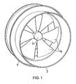
- a propeller unit according to the present invention is illustrated, where the propeller unit comprises an external, stationary casing 1 and a rotatable rotor housing 2.
- the external, stationary casing 1 is securely mounted in a suitable manner to a vessel (not shown), so that the stationary casing 1 forms a stationary unit with the vessel.
- the rotatable rotor housing 2 is mounted internally in the external, stationary casing 1, where the rotatable rotor housing 2 is composed of a number of propeller blades 3 and a propeller hub 5.
- the propeller blades 3 are securely connected to the rotatable rotor housing 2 through the propeller hub 5 and the rotatable rotor housing's 2 internal circumference.
- the rotatable rotor housing's 2 external diameter is smaller than the stationary casing's 1 internal diameter, with the result that when the external, stationary casing 1 and the rotatable rotor housing 2 are assembled, a gap will be created between the rotatable rotor housing's 2 external circumference and the external, stationary casing's 1 internal circumference, where this gap is used for support of the rotatable rotor housing 2 relative to the external, stationary casing 1.
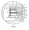
- FIG. 2 This is illustrated in figure 2 , where a collar 13 is provided round the external circumference of the rotatable rotor housing 2, which collar 13 includes a cutout 11.
- a set of permanent magnets 4 are arranged in this cutout 11 .
- the permanent magnets 4 consist of a number of separate, discrete permanent magnet units, where these are arranged one after the other in a row round the entire or parts of the circumference of the cutout 11.
- the permanent magnets 4 are attached to the collar 13 by means of a connecting piece 10.
- the external, stationary casing 1 is closed at one end, this end being provided with a flange 6 which protrudes inwardly in the stationary casing's 2 axial direction.
- a magnet holding device 7 is attached to the flange 6 via a bolt 8.
- a second set of permanent magnets 4 is arranged, consisting of a number of permanent magnet units.
- the permanent magnet units may be arranged round the entire or parts of the circumference of the flange 6.
- the locking device(s) may, for example, be in the form of a locking ring, flanges or the like, this or these being attached in a suitable manner internally in the external, stationary casing 1.
- Any sets of permanent magnets 4 which are provided between the two ends of the propeller unit will only be arranged (without the use of flanges, cutouts, etc.) round the rotatable rotor housing's 1 external circumference and the external, stationary casing's 1 internal circumference. This may be accomplished, for example, by the permanent magnets 4 being connected in a suitable manner to the rotatable rotor housing 2 and the external, stationary casing 1, for example by gluing.
- the permanent magnets 4 are only provided in an area between 145 degrees and 215 degrees of the external, stationary casing's 1 internal circumference, where zero degrees is defined as corresponding to a top point on the rotatable rotor housing 2 in the propeller unit's mounted position, while permanent magnets 4 are provided round the entire external circumference of the rotatable rotor housing 2.
- the permanent magnets 4 which are arranged on the external, stationary casing's 1 internal circumference, in the area between 145 degrees and 215 degrees will have the same polarity as the permanent magnets 4 which are arranged round the rotatable rotor housing's 1 external circumference, with the result that the permanent magnets 4 in the external, stationary casing 1 and the rotatable rotor housing 2 will attempt to repel one another in this defined area.
- the rotatable rotor housing 2 will therefore come into contact with the external, stationary casing 1 in this area to a far lesser extent.
- the permanent magnets' 4 facing surfaces are furthermore covered by a bearing material 9 (see figure 2 ), where this bearing material 9 is more resistant to wear then the permanent magnets 4 are.
- the bearing material 9 can be applied to the permanent magnets' 4 surfaces by spraying or gluing.
- FIG 4 a second embodiment of the present invention is illustrated, where it can be seen that the permanent magnets 4 in the external, stationary casing 1 are now arranged in two areas round the rotatable rotor housing's 2 external circumference, namely in an area between 35 degrees and 325 degrees and in the area between 145 degrees and 215 degrees, where zero degrees is defined as corresponding to a top point on the rotatable rotor housing 2 in the propeller unit's mounted position.
- permanent magnets 4 are arranged round the entire external circumference of the rotatable rotor housing 2.
- the permanent magnets 4 which are arranged on the external, stationary casing's 1 internal circumference, in the area between 145 degrees and 215 degrees, will have the same polarity as the permanent magnets 4 which are arranged round the external circumference of the rotatable rotor housing 1, with the result that the permanent magnets 4 in the external, stationary casing 1 and the rotatable rotor housing 2 will attempt to repel one another in this defined area.
- the rotatable rotor housing 2 will come into contact with the external, stationary casing 1 in this area to a far lesser extent.
- the permanent magnets 4 which are arranged on the external, stationary casing's 1 internal circumference between 35 degrees and 325 degrees will have opposite polarity to the permanent magnets 4 which are arranged round the rotatable rotor housing's 1 external circumference, with the result that the permanent magnets 4 in the external, stationary casing 1 and the rotatable rotor housing 2 will attempt to attract one another in this area.
- the effect of this embodiment will be that the permanent magnets in the casing 1 and the rotor housing 2 will attract one another in the area between 35 degrees and 325 degrees, while the permanent magnets in the area between 145 degrees and 215 degrees will repel one another.
Landscapes
- Engineering & Computer Science (AREA)
- Mechanical Engineering (AREA)
- General Engineering & Computer Science (AREA)
- Chemical & Material Sciences (AREA)
- Combustion & Propulsion (AREA)
- Ocean & Marine Engineering (AREA)
- Power Engineering (AREA)
- Magnetic Bearings And Hydrostatic Bearings (AREA)
- Dynamo-Electric Clutches, Dynamo-Electric Brakes (AREA)
- Toys (AREA)
- Other Liquid Machine Or Engine Such As Wave Power Use (AREA)
- Connection Of Motors, Electrical Generators, Mechanical Devices, And The Like (AREA)
Priority Applications (3)
| Application Number | Priority Date | Filing Date | Title |
|---|---|---|---|
| PL10732479T PL2432683T3 (pl) | 2009-05-20 | 2010-05-12 | Podpora zespołu śruby napędowej dla statku wodnego |
| SI201030359T SI2432683T1 (sl) | 2009-05-20 | 2010-05-12 | Nosilec propelerske enote za plovilo |
| CY20131100989T CY1114671T1 (el) | 2009-05-20 | 2013-11-06 | Υποστηριξη μοναδας ελικας για πλοια |
Applications Claiming Priority (2)
| Application Number | Priority Date | Filing Date | Title |
|---|---|---|---|
| NO20091964A NO331651B1 (no) | 2009-05-20 | 2009-05-20 | Opplagring av propellenhet for et fartøy |
| PCT/NO2010/000175 WO2010134820A2 (en) | 2009-05-20 | 2010-05-12 | Support of propeller unit for a vessel |
Publications (2)
| Publication Number | Publication Date |
|---|---|
| EP2432683A2 EP2432683A2 (en) | 2012-03-28 |
| EP2432683B1 true EP2432683B1 (en) | 2013-09-18 |
Family
ID=43033308
Family Applications (1)
| Application Number | Title | Priority Date | Filing Date |
|---|---|---|---|
| EP10732479.0A Active EP2432683B1 (en) | 2009-05-20 | 2010-05-12 | Support of propeller unit for a vessel |
Country Status (13)
| Country | Link |
|---|---|
| US (1) | US9592897B2 (enExample) |
| EP (1) | EP2432683B1 (enExample) |
| JP (1) | JP5661749B2 (enExample) |
| CN (1) | CN102548840B (enExample) |
| CY (1) | CY1114671T1 (enExample) |
| DK (1) | DK2432683T3 (enExample) |
| ES (1) | ES2435464T3 (enExample) |
| HR (1) | HRP20131117T1 (enExample) |
| NO (1) | NO331651B1 (enExample) |
| PL (1) | PL2432683T3 (enExample) |
| PT (1) | PT2432683E (enExample) |
| SI (1) | SI2432683T1 (enExample) |
| WO (1) | WO2010134820A2 (enExample) |
Families Citing this family (10)
| Publication number | Priority date | Publication date | Assignee | Title |
|---|---|---|---|---|
| CN102632982A (zh) * | 2012-04-28 | 2012-08-15 | 中国船舶重工集团公司第七○二研究所 | 无轴驱动式集成电机推进器 |
| JP6204709B2 (ja) * | 2013-06-11 | 2017-09-27 | 川崎重工業株式会社 | 推力発生装置 |
| DK3241737T3 (en) * | 2013-09-24 | 2019-04-23 | Rolls Royce Marine As | MODULAR AZIMUTH-THRUSTER |
| CN105257561A (zh) * | 2015-09-30 | 2016-01-20 | 王振科 | 一种散热器 |
| CN107140162B (zh) * | 2017-04-13 | 2018-11-20 | 王连山 | 磁悬浮推进器及潜艇 |
| CN107444599A (zh) * | 2017-08-16 | 2017-12-08 | 广州海工船舶设备有限公司 | 一种轮缘式电机驱动的对转螺旋桨驱动装置 |
| CN108058798A (zh) * | 2018-01-04 | 2018-05-22 | 蒋喜臣 | 一种高效能船用推进器 |
| USD915268S1 (en) * | 2019-12-04 | 2021-04-06 | Charles Fultz | Handheld propulsion unit for use by a user in and under water |
| DE102021100135B4 (de) * | 2021-01-07 | 2022-07-14 | Schottel Gmbh | Schiffsantrieb und damit ausgerüstetes Schiff |
| NL2031469B1 (en) * | 2022-03-31 | 2023-10-24 | Insumo B V | Rim driven thruster and method for propelling a ship |
Family Cites Families (23)
| Publication number | Priority date | Publication date | Assignee | Title |
|---|---|---|---|---|
| US5078628A (en) | 1989-06-23 | 1992-01-07 | Newport News Shipbuilding And Dry Dock Company | Marine propulsor |
| US5220231A (en) * | 1990-08-23 | 1993-06-15 | Westinghouse Electric Corp. | Integral motor propulsor unit for water vehicles |
| US5252875A (en) * | 1990-08-23 | 1993-10-12 | Westinghouse Electric Corp. | Integral motor propulsor unit for water vehicles with plural electric motors driving a single propeller |
| US5185545A (en) * | 1990-08-23 | 1993-02-09 | Westinghouse Electric Corp. | Dual propeller shock resistant submersible propulsor unit |
| JPH0589944A (ja) | 1991-09-26 | 1993-04-09 | Shimadzu Corp | 抵抗加熱炉用トランスの混触検知装置 |
| JPH0589944U (ja) * | 1992-05-18 | 1993-12-07 | 光洋精工株式会社 | 回転体 |
| JPH0622499A (ja) * | 1992-07-03 | 1994-01-28 | Ebara Corp | キャンドモータポンプ |
| US5306183A (en) | 1993-02-25 | 1994-04-26 | Harbor Branch Oceanographic Institute Inc. | Propulsion systems for submarine vessels |
| US5408155A (en) * | 1993-10-08 | 1995-04-18 | Westinghouse Electric Corporation | Bearing assembly for an integral motor/propeller unit |
| US5607329A (en) * | 1995-12-21 | 1997-03-04 | The United States Of America As Represented By The Secretary Of The Navy | Integrated motor/marine propulsor with permanent magnet blades |
| JPH10331849A (ja) * | 1997-06-04 | 1998-12-15 | Ricoh Co Ltd | 軸受装置 |
| US5967749A (en) * | 1998-01-08 | 1999-10-19 | Electric Boat Corporation | Controllable pitch propeller arrangement |
| DE69911740T2 (de) * | 1998-01-27 | 2004-08-05 | Hydroring B.V. | Umwandler für fluidumenergie |
| JP3348038B2 (ja) * | 1998-04-08 | 2002-11-20 | 韓国電力公社 | 強い浮上力の高温超伝導ベアリング、および、フライホイールエネルギー貯蔵装置 |
| US6836028B2 (en) * | 2001-10-29 | 2004-12-28 | Frontier Engineer Products | Segmented arc generator |
| US6837757B2 (en) | 2002-04-16 | 2005-01-04 | Electric Boat Corporation | Rim-driven propulsion pod arrangement |
| NO322779B1 (no) * | 2004-08-25 | 2006-12-11 | Norpropeller As | Lager med permanentmagnetiske elementer |
| NL1029389C2 (nl) | 2005-06-30 | 2007-01-04 | Marifin Beheer B V | Asloze schroef. |
| EP1878913B1 (en) * | 2006-07-14 | 2013-03-13 | OpenHydro Group Limited | Bi-directional tidal flow hydroelectric turbine |
| GB2440400A (en) * | 2006-07-26 | 2008-01-30 | Rolls Royce Plc | Starting a rim driven pm motor by an associated induction motor |
| CN200982347Y (zh) * | 2006-11-15 | 2007-11-28 | 周峻雄 | 永磁悬浮轴承 |
| EP2112370B1 (en) * | 2008-04-22 | 2016-08-31 | OpenHydro Group Limited | A hydro-electric turbine having a magnetic bearing |
| GB201011574D0 (en) | 2010-07-09 | 2010-08-25 | Element Six Ltd | PCBN material |
-
2009
- 2009-05-20 NO NO20091964A patent/NO331651B1/no unknown
-
2010
- 2010-05-12 JP JP2012511779A patent/JP5661749B2/ja active Active
- 2010-05-12 WO PCT/NO2010/000175 patent/WO2010134820A2/en not_active Ceased
- 2010-05-12 HR HRP20131117AT patent/HRP20131117T1/hr unknown
- 2010-05-12 SI SI201030359T patent/SI2432683T1/sl unknown
- 2010-05-12 CN CN201080032681.XA patent/CN102548840B/zh active Active
- 2010-05-12 PT PT107324790T patent/PT2432683E/pt unknown
- 2010-05-12 PL PL10732479T patent/PL2432683T3/pl unknown
- 2010-05-12 EP EP10732479.0A patent/EP2432683B1/en active Active
- 2010-05-12 US US13/321,174 patent/US9592897B2/en active Active
- 2010-05-12 DK DK10732479.0T patent/DK2432683T3/da active
- 2010-05-12 ES ES10732479T patent/ES2435464T3/es active Active
-
2013
- 2013-11-06 CY CY20131100989T patent/CY1114671T1/el unknown
Also Published As
| Publication number | Publication date |
|---|---|
| PT2432683E (pt) | 2013-10-17 |
| HRP20131117T1 (hr) | 2014-01-03 |
| CY1114671T1 (el) | 2016-10-05 |
| US20120122356A1 (en) | 2012-05-17 |
| WO2010134820A3 (en) | 2011-01-06 |
| US9592897B2 (en) | 2017-03-14 |
| JP5661749B2 (ja) | 2015-01-28 |
| DK2432683T3 (da) | 2014-01-13 |
| EP2432683A2 (en) | 2012-03-28 |
| ES2435464T3 (es) | 2013-12-19 |
| NO331651B1 (no) | 2012-02-13 |
| PL2432683T3 (pl) | 2014-03-31 |
| JP2012527590A (ja) | 2012-11-08 |
| SI2432683T1 (sl) | 2014-01-31 |
| WO2010134820A2 (en) | 2010-11-25 |
| NO20091964L (no) | 2010-11-22 |
| CN102548840B (zh) | 2015-05-13 |
| CN102548840A (zh) | 2012-07-04 |
| HK1167124A1 (en) | 2012-11-23 |
Similar Documents
| Publication | Publication Date | Title |
|---|---|---|
| EP2432683B1 (en) | Support of propeller unit for a vessel | |
| US8294316B2 (en) | Electrical power generation apparatus for contra-rotating open-rotor aircraft propulsion system | |
| EP3046232B1 (en) | One-piece end winding support with integrated lubricant manifold | |
| US20120093668A1 (en) | Rim driven thruster having propeller drive modules | |
| US8742612B1 (en) | Turbine having counter-rotating armature and field | |
| US20250047163A1 (en) | Electrical motor with an intrinsic cooling system | |
| US20020154999A1 (en) | Heating device and method for deployable ram air turbine | |
| CA2851942A1 (en) | A propulsion unit | |
| US20090146430A1 (en) | Tidal/water current electrical generating system | |
| KR102340581B1 (ko) | 자석 차폐방법을 이용한 회전원판 발전장치 및 이를 이용한 발전방법 | |
| US20220231572A1 (en) | Hollow, magnetic flywheel and related generator systems | |
| KR101185929B1 (ko) | 선박용 추진 장치 및 이를 포함하는 선박 | |
| EP2594479A1 (en) | Rim driven thruster having propeller drive modules | |
| HK1167124B (en) | Support of propeller unit for a vessel | |
| US6787934B2 (en) | Turbine system | |
| CN103158850A (zh) | 具有螺旋桨驱动模块的环圈驱动推力器 | |
| KR20180064057A (ko) | 수중이동체 | |
| US9787151B2 (en) | Radial flux alternator | |
| CN214267930U (zh) | 推进器和水上运行装置 | |
| CN214267931U (zh) | 推进器和水上运行设备 | |
| CN116443228B (zh) | 船舶大功率非接触式感应励磁轮缘推进器 | |
| CN103158847A (zh) | 具有横向通量马达的环圈驱动推力器 | |
| KR930021497A (ko) | 일체로 형성된 모터를 갖는, 선박용 추진장치 | |
| CHO et al. | A Marine Propulsion System for Underwater Vehicles(Patent Application) |
Legal Events
| Date | Code | Title | Description |
|---|---|---|---|
| PUAI | Public reference made under article 153(3) epc to a published international application that has entered the european phase |
Free format text: ORIGINAL CODE: 0009012 |
|
| 17P | Request for examination filed |
Effective date: 20111220 |
|
| AK | Designated contracting states |
Kind code of ref document: A2 Designated state(s): AL AT BE BG CH CY CZ DE DK EE ES FI FR GB GR HR HU IE IS IT LI LT LU LV MC MK MT NL NO PL PT RO SE SI SK SM TR |
|
| DAX | Request for extension of the european patent (deleted) | ||
| 17Q | First examination report despatched |
Effective date: 20121001 |
|
| REG | Reference to a national code |
Ref country code: HK Ref legal event code: DE Ref document number: 1167124 Country of ref document: HK |
|
| GRAP | Despatch of communication of intention to grant a patent |
Free format text: ORIGINAL CODE: EPIDOSNIGR1 |
|
| INTG | Intention to grant announced |
Effective date: 20130412 |
|
| GRAS | Grant fee paid |
Free format text: ORIGINAL CODE: EPIDOSNIGR3 |
|
| GRAA | (expected) grant |
Free format text: ORIGINAL CODE: 0009210 |
|
| AK | Designated contracting states |
Kind code of ref document: B1 Designated state(s): AL AT BE BG CH CY CZ DE DK EE ES FI FR GB GR HR HU IE IS IT LI LT LU LV MC MK MT NL NO PL PT RO SE SI SK SM TR |
|
| REG | Reference to a national code |
Ref country code: GB Ref legal event code: FG4D |
|
| REG | Reference to a national code |
Ref country code: CH Ref legal event code: EP |
|
| REG | Reference to a national code |
Ref country code: IE Ref legal event code: FG4D |
|
| REG | Reference to a national code |
Ref country code: AT Ref legal event code: REF Ref document number: 632590 Country of ref document: AT Kind code of ref document: T Effective date: 20131015 |
|
| REG | Reference to a national code |
Ref country code: PT Ref legal event code: SC4A Free format text: AVAILABILITY OF NATIONAL TRANSLATION Effective date: 20131009 |
|
| REG | Reference to a national code |
Ref country code: DE Ref legal event code: R096 Ref document number: 602010010394 Country of ref document: DE Effective date: 20131114 |
|
| REG | Reference to a national code |
Ref country code: HR Ref legal event code: TUEP Ref document number: P20131117 Country of ref document: HR |
|
| REG | Reference to a national code |
Ref country code: NL Ref legal event code: T3 Ref country code: RO Ref legal event code: EPE |
|
| REG | Reference to a national code |
Ref country code: SE Ref legal event code: TRGR |
|
| REG | Reference to a national code |
Ref country code: ES Ref legal event code: FG2A Ref document number: 2435464 Country of ref document: ES Kind code of ref document: T3 Effective date: 20131219 |
|
| REG | Reference to a national code |
Ref country code: HR Ref legal event code: T1PR Ref document number: P20131117 Country of ref document: HR |
|
| REG | Reference to a national code |
Ref country code: DK Ref legal event code: T3 Effective date: 20140108 |
|
| REG | Reference to a national code |
Ref country code: GR Ref legal event code: EP Ref document number: 20130402279 Country of ref document: GR Effective date: 20131118 |
|
| REG | Reference to a national code |
Ref country code: HK Ref legal event code: GR Ref document number: 1167124 Country of ref document: HK |
|
| PG25 | Lapsed in a contracting state [announced via postgrant information from national office to epo] |
Ref country code: NO Free format text: LAPSE BECAUSE OF FAILURE TO SUBMIT A TRANSLATION OF THE DESCRIPTION OR TO PAY THE FEE WITHIN THE PRESCRIBED TIME-LIMIT Effective date: 20131218 |
|
| REG | Reference to a national code |
Ref country code: EE Ref legal event code: FG4A Ref document number: E008697 Country of ref document: EE Effective date: 20131204 |
|
| REG | Reference to a national code |
Ref country code: SK Ref legal event code: T3 Ref document number: E 15259 Country of ref document: SK |
|
| REG | Reference to a national code |
Ref country code: DE Ref legal event code: R097 Ref document number: 602010010394 Country of ref document: DE |
|
| PLBE | No opposition filed within time limit |
Free format text: ORIGINAL CODE: 0009261 |
|
| STAA | Information on the status of an ep patent application or granted ep patent |
Free format text: STATUS: NO OPPOSITION FILED WITHIN TIME LIMIT |
|
| REG | Reference to a national code |
Ref country code: HU Ref legal event code: AG4A Ref document number: E019876 Country of ref document: HU |
|
| 26N | No opposition filed |
Effective date: 20140619 |
|
| REG | Reference to a national code |
Ref country code: DE Ref legal event code: R097 Ref document number: 602010010394 Country of ref document: DE Effective date: 20140619 |
|
| PGFP | Annual fee paid to national office [announced via postgrant information from national office to epo] |
Ref country code: MK Payment date: 20150512 Year of fee payment: 6 Ref country code: LU Payment date: 20150528 Year of fee payment: 6 |
|
| PGFP | Annual fee paid to national office [announced via postgrant information from national office to epo] |
Ref country code: RO Payment date: 20150424 Year of fee payment: 6 Ref country code: BG Payment date: 20150513 Year of fee payment: 6 Ref country code: CY Payment date: 20150427 Year of fee payment: 6 Ref country code: SI Payment date: 20150423 Year of fee payment: 6 Ref country code: MC Payment date: 20150515 Year of fee payment: 6 Ref country code: CH Payment date: 20150521 Year of fee payment: 6 Ref country code: SK Payment date: 20150511 Year of fee payment: 6 Ref country code: LT Payment date: 20150422 Year of fee payment: 6 Ref country code: EE Payment date: 20150513 Year of fee payment: 6 Ref country code: CZ Payment date: 20150511 Year of fee payment: 6 |
|
| PGFP | Annual fee paid to national office [announced via postgrant information from national office to epo] |
Ref country code: AT Payment date: 20150521 Year of fee payment: 6 Ref country code: PL Payment date: 20150422 Year of fee payment: 6 Ref country code: IS Payment date: 20150420 Year of fee payment: 6 Ref country code: BE Payment date: 20150520 Year of fee payment: 6 Ref country code: HU Payment date: 20150520 Year of fee payment: 6 Ref country code: IE Payment date: 20150522 Year of fee payment: 6 Ref country code: LV Payment date: 20150512 Year of fee payment: 6 |
|
| PG25 | Lapsed in a contracting state [announced via postgrant information from national office to epo] |
Ref country code: SM Free format text: LAPSE BECAUSE OF FAILURE TO SUBMIT A TRANSLATION OF THE DESCRIPTION OR TO PAY THE FEE WITHIN THE PRESCRIBED TIME-LIMIT Effective date: 20130918 |
|
| REG | Reference to a national code |
Ref country code: FR Ref legal event code: PLFP Year of fee payment: 7 |
|
| PG25 | Lapsed in a contracting state [announced via postgrant information from national office to epo] |
Ref country code: BE Free format text: LAPSE BECAUSE OF NON-PAYMENT OF DUE FEES Effective date: 20160531 |
|
| REG | Reference to a national code |
Ref country code: LT Ref legal event code: MM4D Effective date: 20160512 |
|
| REG | Reference to a national code |
Ref country code: EE Ref legal event code: MM4A Ref document number: E008697 Country of ref document: EE Effective date: 20160531 |
|
| PG25 | Lapsed in a contracting state [announced via postgrant information from national office to epo] |
Ref country code: LU Free format text: LAPSE BECAUSE OF NON-PAYMENT OF DUE FEES Effective date: 20160512 |
|
| PGFP | Annual fee paid to national office [announced via postgrant information from national office to epo] |
Ref country code: MT Payment date: 20150427 Year of fee payment: 6 |
|
| REG | Reference to a national code |
Ref country code: CH Ref legal event code: PL |
|
| REG | Reference to a national code |
Ref country code: AT Ref legal event code: MM01 Ref document number: 632590 Country of ref document: AT Kind code of ref document: T Effective date: 20160512 |
|
| PG25 | Lapsed in a contracting state [announced via postgrant information from national office to epo] |
Ref country code: SK Free format text: LAPSE BECAUSE OF NON-PAYMENT OF DUE FEES Effective date: 20160512 Ref country code: CH Free format text: LAPSE BECAUSE OF NON-PAYMENT OF DUE FEES Effective date: 20160531 Ref country code: LT Free format text: LAPSE BECAUSE OF NON-PAYMENT OF DUE FEES Effective date: 20160512 Ref country code: EE Free format text: LAPSE BECAUSE OF NON-PAYMENT OF DUE FEES Effective date: 20160531 Ref country code: IS Free format text: LAPSE BECAUSE OF FAILURE TO SUBMIT A TRANSLATION OF THE DESCRIPTION OR TO PAY THE FEE WITHIN THE PRESCRIBED TIME-LIMIT Effective date: 20161201 Ref country code: CZ Free format text: LAPSE BECAUSE OF NON-PAYMENT OF DUE FEES Effective date: 20160512 Ref country code: CY Free format text: LAPSE BECAUSE OF NON-PAYMENT OF DUE FEES Effective date: 20160512 Ref country code: LI Free format text: LAPSE BECAUSE OF NON-PAYMENT OF DUE FEES Effective date: 20160531 |
|
| REG | Reference to a national code |
Ref country code: SK Ref legal event code: MM4A Ref document number: E 15259 Country of ref document: SK Effective date: 20160512 |
|
| REG | Reference to a national code |
Ref country code: IE Ref legal event code: MM4A |
|
| PG25 | Lapsed in a contracting state [announced via postgrant information from national office to epo] |
Ref country code: LV Free format text: LAPSE BECAUSE OF NON-PAYMENT OF DUE FEES Effective date: 20160512 Ref country code: BG Free format text: LAPSE BECAUSE OF NON-PAYMENT OF DUE FEES Effective date: 20161130 Ref country code: AT Free format text: LAPSE BECAUSE OF NON-PAYMENT OF DUE FEES Effective date: 20160512 |
|
| REG | Reference to a national code |
Ref country code: SI Ref legal event code: KO00 Effective date: 20170216 |
|
| PG25 | Lapsed in a contracting state [announced via postgrant information from national office to epo] |
Ref country code: HU Free format text: LAPSE BECAUSE OF NON-PAYMENT OF DUE FEES Effective date: 20160513 Ref country code: RO Free format text: LAPSE BECAUSE OF NON-PAYMENT OF DUE FEES Effective date: 20160512 |
|
| REG | Reference to a national code |
Ref country code: FR Ref legal event code: PLFP Year of fee payment: 8 |
|
| PG25 | Lapsed in a contracting state [announced via postgrant information from national office to epo] |
Ref country code: IE Free format text: LAPSE BECAUSE OF NON-PAYMENT OF DUE FEES Effective date: 20160512 Ref country code: SI Free format text: LAPSE BECAUSE OF NON-PAYMENT OF DUE FEES Effective date: 20160513 |
|
| PG25 | Lapsed in a contracting state [announced via postgrant information from national office to epo] |
Ref country code: PL Free format text: LAPSE BECAUSE OF NON-PAYMENT OF DUE FEES Effective date: 20160512 |
|
| REG | Reference to a national code |
Ref country code: FR Ref legal event code: PLFP Year of fee payment: 9 |
|
| PG25 | Lapsed in a contracting state [announced via postgrant information from national office to epo] |
Ref country code: MC Free format text: LAPSE BECAUSE OF NON-PAYMENT OF DUE FEES Effective date: 20160531 |
|
| PG25 | Lapsed in a contracting state [announced via postgrant information from national office to epo] |
Ref country code: MK Free format text: LAPSE BECAUSE OF NON-PAYMENT OF DUE FEES Effective date: 20160513 |
|
| PG25 | Lapsed in a contracting state [announced via postgrant information from national office to epo] |
Ref country code: MT Free format text: LAPSE BECAUSE OF NON-PAYMENT OF DUE FEES Effective date: 20160512 |
|
| PG25 | Lapsed in a contracting state [announced via postgrant information from national office to epo] |
Ref country code: AL Free format text: LAPSE BECAUSE OF FAILURE TO SUBMIT A TRANSLATION OF THE DESCRIPTION OR TO PAY THE FEE WITHIN THE PRESCRIBED TIME-LIMIT Effective date: 20130918 |
|
| REG | Reference to a national code |
Ref country code: HR Ref legal event code: ODRP Ref document number: P20131117 Country of ref document: HR Payment date: 20190419 Year of fee payment: 10 |
|
| REG | Reference to a national code |
Ref country code: HR Ref legal event code: ODRP Ref document number: P20131117 Country of ref document: HR Payment date: 20200507 Year of fee payment: 11 |
|
| REG | Reference to a national code |
Ref country code: NL Ref legal event code: HC Owner name: KONGSBERG MARITIME CM AS; NO Free format text: DETAILS ASSIGNMENT: CHANGE OF OWNER(S), CHANGE OF OWNER(S) NAME; FORMER OWNER NAME: ROLLS-ROYCE MARINE AS Effective date: 20200731 |
|
| REG | Reference to a national code |
Ref country code: FI Ref legal event code: PCE Owner name: KONGSBERG MARITIME CM AS |
|
| REG | Reference to a national code |
Ref country code: DE Ref legal event code: R081 Ref document number: 602010010394 Country of ref document: DE Owner name: KONGSBERG MARITIME AS, NO Free format text: FORMER OWNER: ROLLS-ROYCE MARINE AS, ULSTEINVIK, NO Ref country code: DE Ref legal event code: R081 Ref document number: 602010010394 Country of ref document: DE Owner name: KONGSBERG MARITIME CM AS, NO Free format text: FORMER OWNER: ROLLS-ROYCE MARINE AS, ULSTEINVIK, NO |
|
| REG | Reference to a national code |
Ref country code: ES Ref legal event code: PC2A Owner name: KONGSBERG MARITIME CM AS Effective date: 20201105 |
|
| PG25 | Lapsed in a contracting state [announced via postgrant information from national office to epo] |
Ref country code: GR Free format text: LAPSE BECAUSE OF NON-PAYMENT OF DUE FEES Effective date: 20201209 |
|
| REG | Reference to a national code |
Ref country code: HR Ref legal event code: ODRP Ref document number: P20131117 Country of ref document: HR Payment date: 20210504 Year of fee payment: 12 |
|
| REG | Reference to a national code |
Ref country code: FI Ref legal event code: PCE Owner name: KONGSBERG MARITIME AS |
|
| REG | Reference to a national code |
Ref country code: NL Ref legal event code: PD Owner name: KONGSBERG MARITIME AS; NO Free format text: DETAILS ASSIGNMENT: CHANGE OF OWNER(S), MERGE; FORMER OWNER NAME: KONGSBERG MARITIME CM AS Effective date: 20211214 |
|
| REG | Reference to a national code |
Ref country code: GB Ref legal event code: 732E Free format text: REGISTERED BETWEEN 20211230 AND 20220105 |
|
| REG | Reference to a national code |
Ref country code: DE Ref legal event code: R081 Ref document number: 602010010394 Country of ref document: DE Owner name: KONGSBERG MARITIME AS, NO Free format text: FORMER OWNER: KONGSBERG MARITIME CM AS, ALESUND, NO |
|
| REG | Reference to a national code |
Ref country code: ES Ref legal event code: PC2A Owner name: KONGSBERG MARITIME AS Effective date: 20220216 |
|
| REG | Reference to a national code |
Ref country code: HR Ref legal event code: PNAN Ref document number: P20131117 Country of ref document: HR Owner name: KONGSBERG MARITIME AS, NO |
|
| REG | Reference to a national code |
Ref country code: HR Ref legal event code: ODRP Ref document number: P20131117 Country of ref document: HR Payment date: 20220502 Year of fee payment: 13 |
|
| REG | Reference to a national code |
Ref country code: HR Ref legal event code: ODRP Ref document number: P20131117 Country of ref document: HR Payment date: 20230315 Year of fee payment: 14 |
|
| P01 | Opt-out of the competence of the unified patent court (upc) registered |
Effective date: 20230530 |
|
| REG | Reference to a national code |
Ref country code: HR Ref legal event code: ODRP Ref document number: P20131117 Country of ref document: HR Payment date: 20240419 Year of fee payment: 15 |
|
| REG | Reference to a national code |
Ref country code: HR Ref legal event code: ODRP Ref document number: P20131117 Country of ref document: HR Payment date: 20250425 Year of fee payment: 16 |
|
| PGFP | Annual fee paid to national office [announced via postgrant information from national office to epo] |
Ref country code: NL Payment date: 20250526 Year of fee payment: 16 |
|
| PGFP | Annual fee paid to national office [announced via postgrant information from national office to epo] |
Ref country code: FI Payment date: 20250526 Year of fee payment: 16 |
|
| PGFP | Annual fee paid to national office [announced via postgrant information from national office to epo] |
Ref country code: DE Payment date: 20250529 Year of fee payment: 16 |
|
| PGFP | Annual fee paid to national office [announced via postgrant information from national office to epo] |
Ref country code: GB Payment date: 20250527 Year of fee payment: 16 Ref country code: ES Payment date: 20250602 Year of fee payment: 16 Ref country code: DK Payment date: 20250526 Year of fee payment: 16 |
|
| PGFP | Annual fee paid to national office [announced via postgrant information from national office to epo] |
Ref country code: IT Payment date: 20250521 Year of fee payment: 16 |
|
| PGFP | Annual fee paid to national office [announced via postgrant information from national office to epo] |
Ref country code: HR Payment date: 20250425 Year of fee payment: 16 |
|
| PGFP | Annual fee paid to national office [announced via postgrant information from national office to epo] |
Ref country code: PT Payment date: 20250421 Year of fee payment: 16 |
|
| PGFP | Annual fee paid to national office [announced via postgrant information from national office to epo] |
Ref country code: FR Payment date: 20250526 Year of fee payment: 16 |
|
| PGFP | Annual fee paid to national office [announced via postgrant information from national office to epo] |
Ref country code: TR Payment date: 20250428 Year of fee payment: 16 |
|
| PGFP | Annual fee paid to national office [announced via postgrant information from national office to epo] |
Ref country code: SE Payment date: 20250527 Year of fee payment: 16 |