EP2432600B1 - Dispositif de generation d'ondes acoustiques et installation incluant plusieurs de ces dispositifs - Google Patents
Dispositif de generation d'ondes acoustiques et installation incluant plusieurs de ces dispositifs Download PDFInfo
- Publication number
- EP2432600B1 EP2432600B1 EP10727042.3A EP10727042A EP2432600B1 EP 2432600 B1 EP2432600 B1 EP 2432600B1 EP 10727042 A EP10727042 A EP 10727042A EP 2432600 B1 EP2432600 B1 EP 2432600B1
- Authority
- EP
- European Patent Office
- Prior art keywords
- walls
- assembly
- potentials
- acoustic
- assemblies
- Prior art date
- Legal status (The legal status is an assumption and is not a legal conclusion. Google has not performed a legal analysis and makes no representation as to the accuracy of the status listed.)
- Not-in-force
Links
Images


Classifications
-
- G—PHYSICS
- G10—MUSICAL INSTRUMENTS; ACOUSTICS
- G10K—SOUND-PRODUCING DEVICES; METHODS OR DEVICES FOR PROTECTING AGAINST, OR FOR DAMPING, NOISE OR OTHER ACOUSTIC WAVES IN GENERAL; ACOUSTICS NOT OTHERWISE PROVIDED FOR
- G10K15/00—Acoustics not otherwise provided for
- G10K15/04—Sound-producing devices
-
- H—ELECTRICITY
- H04—ELECTRIC COMMUNICATION TECHNIQUE
- H04R—LOUDSPEAKERS, MICROPHONES, GRAMOPHONE PICK-UPS OR LIKE ACOUSTIC ELECTROMECHANICAL TRANSDUCERS; ELECTRIC HEARING AIDS; PUBLIC ADDRESS SYSTEMS
- H04R19/00—Electrostatic transducers
- H04R19/02—Loudspeakers
-
- H—ELECTRICITY
- H04—ELECTRIC COMMUNICATION TECHNIQUE
- H04R—LOUDSPEAKERS, MICROPHONES, GRAMOPHONE PICK-UPS OR LIKE ACOUSTIC ELECTROMECHANICAL TRANSDUCERS; ELECTRIC HEARING AIDS; PUBLIC ADDRESS SYSTEMS
- H04R31/00—Apparatus or processes specially adapted for the manufacture of transducers or diaphragms therefor
- H04R31/006—Interconnection of transducer parts
-
- H—ELECTRICITY
- H04—ELECTRIC COMMUNICATION TECHNIQUE
- H04R—LOUDSPEAKERS, MICROPHONES, GRAMOPHONE PICK-UPS OR LIKE ACOUSTIC ELECTROMECHANICAL TRANSDUCERS; ELECTRIC HEARING AIDS; PUBLIC ADDRESS SYSTEMS
- H04R2201/00—Details of transducers, loudspeakers or microphones covered by H04R1/00 but not provided for in any of its subgroups
- H04R2201/003—Mems transducers or their use
Definitions
- the invention relates to the field of electroacoustic sources, and more particularly to sources intended to operate in networks for generating extended acoustic wave systems shaped according to very precise surfaces.
- the generation of such waves is required in active noise control and detection or imaging applications, and to a lesser extent in sound reproduction applications.
- It relates more particularly to a new electroacoustic dipole structure, like the various non-baffled speakers, which is distinguished by a unitary pressure control function.
- monopolar sources involves modulating their flow rate according to the component of the normal speed on the surface of the screen, which imposes measuring this speed; with dipole sources, it is a matter of opposing the acoustic pressure incident pressure, pressure more easily accessible to the measurement with a microphone.
- the usual monopolar sources are in fact constituted by fundamentally dipolar sources with two speaking faces, which are baffled to avoid the external action of one of the faces. This results in an increase in the congestion penalizing in active noise control applications in particular, where their compactness must contribute to the visual transparency of the screens.
- the problem to be solved by the invention is that of making electroacoustic sources dipole, compact, unitary response pressure and no response time.
- the invention relates to a dipole device for generating acoustic waves, that is to say more specifically, couples of acoustic waves of opposite pressure, propagating in each direction in the opposite direction, parallel to defined discontinuity surfaces. by the geometry of the network of sources and the respective delays of the commands applied to the sources, themselves dipoles.
- the pressure differential resulting from this pair of waves at the level of the discontinuity surfaces reflects the coupling of the variable dipole flow created by the sources themselves to the external acoustic medium.
- these sources are locally defined as dipole pumps, that is to say antisymmetric, two vents, generating flow in the ambient fluid.
- This fluid electrically insulating air or liquid, can be considered as incompressible in the operating conditions of the pump (near-field acoustic conditions) in the frequency domain of use of the dipole.
- the acoustic coupling of this flow is such that the pressure differential created on such pairs of waves is strictly proportional to the general pressure differential which generates the flow within the pump which constitutes the source. It is modulated by a directivity factor according to the direction of the couples.
- the invention therefore relates more particularly to a local dipolar flow generation device whose pressure differential is controlled.
- this device is characterized in that it comprises a set of substantially identical deformable walls and planar, parallel, made of electrically conductive material. These walls are stacked regularly, and advantageously separated by spacers, flat and of equal thickness, so as to define between them successive volumes, confined, substantially identical, which open alternately on two opposite faces of this set by appropriate openings.
- It also comprises an enclosure that contains this set of walls and has two cavities situated facing the faces where the openings of the defined volumes open, confined between the walls. These cavities communicate themselves with the external environment by two openings of revolution which constitute the two symmetrical vents of the dipole.
- This device also comprises means for applying, in a controlled and variable manner, an electric field between pairs of successive walls, so as to create a pressure differential between pairs of contiguous volumes, the electric field being applied alternately to one of the volumes , to the exclusion of the other, according to the sign of the pressure differential to be created.
- This pressure differential itself induces a succession of distances and approximations of the opposite walls, and therefore of opposite volume variations which cause the desired alternating dipole flow. This flow is established outside the enclosure through the two vents through which it closes.
- the device according to the invention acts by causing the opposite alternating deformation of multiple volumes, opening on two vents, volumes which by contracting and expanding successively, in space and time, aspire or reject the fluid they contain, in equal quantities and create from these vents an external flow potential velocity, dipole-like, almost revolution.
- the electric field applied in an inter-wall space causes the walls concerned to be alternately attracted or not to each other, whereby the corresponding volume decreases by an amount equal to that of which the related volume where the field is not applied.
- a dipolar structure potential flow is generated which, by the combined laws of fluid mechanics and acoustics, gives rise to a system of pairs of acoustic waves propagating in opposite directions and signals. , and whose discontinuity plane passes through the center of symmetry of the vents.
- This device therefore constitutes an acoustic dipolar source.
- the device according to the invention makes it possible to control by electric means the pressure differential at the origin of the dipolar flow, and hence the pressure differential of the acoustic wave pairs induced by this flow.
- each device is ideally acoustically coupled to a single pair of acoustic waves, the fundamental waves of the grating only generated for a frequency spectrum of the acoustic signals bounded above the cutoff frequency (f 0 ). of the network, let f 0 # c / a (where 'it is the celerity of the sound, and'has' the geometrical pitch of the network).
- f 0 # c / a where 'it is the celerity of the sound, and'has' the geometrical pitch of the network.
- the pressure difference between the fundamental acoustic waves generated is only a definite fraction of the pressure differential internal to the device, because of the inertial pressure drop originating in the flows of very close field, adapting those of the dipole to those of the produced waves.
- the transfer function between the pressure differentials is unitary, which is the first fundamental property required in noise-canceling application, and a particularly advantageous property in other applications.
- the various walls of the device are delimited and separated by spacers elements, waterproof, constant thickness in the form of U.
- the open portions of these elements, stacked head to tail, are alternately oriented towards one or the other of the faces where the volumes defined between the different walls open, faces themselves in communication with one or the other of the vents of the dipole.
- the volumes created between the walls are delimited on the one hand, by the walls themselves, and on the other hand, by a spacer element, ensuring both the spacing between the walls and the delimitation of the walls. space through which the fluid will flow transversely, entering or leaving depending on the movement of the walls.
- the choice of the material and the thickness of the walls implies that the elastic walls have, in the acoustic frequency domain considered, a preponderant inertial behavior, which imposes a first natural frequency of membrane of the wall, stretched on the U-shaped spacer. , low enough compared to the average frequency of the spectrum.
- the choice of material is preferentially on an elastomeric material of very low YOUNG modulus (typically of the order of 0.01 GPa), slightly stretched on the spacers and of small thickness (of the order of a few tenths of a mm).
- the device advantageously groups the walls by subassembly of four walls. These subassemblies form repetitive patterns, juxtaposed, in which the walls of the same rank in each subassembly are controlled by the same electrical control potential: let V 1 (t), V 2 (t), V 3 (t ), V 4 (t) defined from a common alternating control potential V 0 (t), developed itself, electronically, from the differential pressure signal to be delivered by the device, ie ⁇ P 0 (t) , realizing the following function: V 0 t ⁇ ⁇ ⁇ P 0 t
- Vo (t) is created from the square root of the module of the pressure to be delivered to take account of the fact that the electrostatic attraction obtained is proportional to the square of the electric field, for the linearity requirement of the transfer function.
- the pressure differential of the generated wave pairs is proportional to the control pressure differential ⁇ P 0 (t), and these two types of differentials are concomitant in the conditions of use of the dipole.
- V 1 (t), V 2 (t), V 3 (t), V 4 (t) are not applied directly to the walls because these vibrating walls, the charges induced on their surface are not not perfectly proportional. They are therefore applied through the electronic circuits of suitable control which correct so that it is the injected electric charges are indeed proportionate to the instructions: V2, V3, V4, so this preserve the linearity of the transfer function.
- the pressure differential created in the inter-wall spaces in fact has an amplitude strictly proportional to the square of the fields, so electric charges injected on the walls.
- the dielectric strength of the medium defines the maximum applicable potentials and therefore the maximum amplitude of the sound pressure differential that the device can deliver.
- the device may advantageously comprise two microphonic sensors, close to the two vents, respectively, so as to evaluate the pressure differential actually generated and correct the control by an electronic control loop. appropriate.
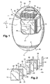
- the device 1 is in the form of a chamber 2 of revolution having two openings or circular vents 3.4 arranged symmetrically with respect to the median plane P.
- the general shape of this enclosure will be generally ellipsoidal, elongated along the axis of the dipole as shown in figure 1 , or on the contrary flattened along the same axis according to the dimensions of the active body 10, or adapted from such a form according to the applications.
- the enclosure 2 encloses an assembly 10 of walls 11, 12, 13, 14 separated by spacer elements 21, 22, 23.
- This set of walls 10 has two preferred faces 15, 16, which open on two internal cavities 17, 18 , sealed internally on the periphery of the assembly 10, by two rigid diaphragms 19 connecting the outer contours of the planes 15, 16 and that of the enclosure 2.
- the cavities 17, 18 are capped with two rigid caps 35, 36 which close the enclosure, while presenting at their base two circular, grid-shaped openings, of section adapted to the flows, constituting two vents 3, 4 which put them into communication with the external environment.
- the device 1 also includes electronic control means 41, distributed in the available volume around the assembly 10, and in particular the four spaces formed between the set of walls 10 and the enclosure. These control means ensure the generation of the electric potentials applied to the walls 11, 12, 13, 14.
- the device also comprises two pressure sensors 70, 71 connected to the electronic control 41 to provide various slave control functions.
- the assembly 10 of walls is constituted by the assembly of various elements.
- the number of walls represented in the figure 2 is intentionally reduced, to facilitate understanding.
- the walls themselves consist of stretched deformable membranes, electrically conductive. More specifically, these membranes are made from films of conductive elastomeric material, typically having a secant Young's modulus of the order of 0.01 GPa, for a thickness of the order of a few tenths of a millimeter, for operation in aerial acoustics.
- Each of the walls 11-14 has an electrical connection 31-34 allowing, as will be explained below, the connection with variable potentials.
- the various membranes 11-14 are separated by insulating spacer members 21-24 of constant thickness, of the order of one millimeter in air.
- each spacer element has a generally U-shaped, which in the illustrated form has three legs 55, 56, 57, which are arranged on three sides of the perimeter of the walls 11-14.
- the spacer elements extend over only part of their perimeter, so as to define an opening zone 28 to connect the closed volume between two successive walls 11 , 12 and the cavity 17,18.
- two successive spacer elements 21, 22 are arranged head to tail, so that their openings are alternately oriented on the two opposite faces 15, 16 of the assembly.
- the volumes defined between the walls 11, 12 and the walls 12, 13 are open in opposite directions.
- the spacer is produced by molding an insulating plastic material advantageously reinforced with fibers, according to an imprint profile U. From this spacer, and a shim adjusting in the inner part of the U, an impression is made, which by pressing and vulcanization allows to obtain the membrane thickness required bonded. It is advantageously observed that the removal of the elastomeric material from the membrane, after molding, gives the membrane a favorable mechanical pretension.
- the assembly 10 of membranes thus comprises a succession of volumes 26, 27 which communicate with the outside via openings 28, 29 are oriented on opposite faces 16, 15 of the assembly opposite the cavities 18,17 of enclosure 2.
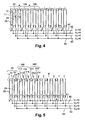
- the different walls are arranged by elementary patterns 40 of four walls.
- the walls 11, 111, 211 of the successive patterns 40, 140, 240 are all connected to the common potential V 1 .
- the walls 12, 112, 212 are connected to a potential V 2 , the walls 13, 113, 213 to the potential V 3 and the walls 14, 114 and 214 to the potential V 4 .
- One way of developing these potentials as a function of the set pressure differential ⁇ P 0 (t) is described in FIG. figure 6 .
- the control electronics makes the charges injected on the walls are proportional, in amplitude, to the square root of the set pressure differential
- a module 605 determines the square root of this absolute value, which determines the control potential V 0 (t) present at 607. This potential value is converted into an electric charge value by the converter 608, a load injected into a bus 62. feeding a quarter of the walls.
- modules 612, 613 make it possible to calculate Heaviside step functions for the values of ⁇ P 0 (t). More precisely, the module 612 has for output a unit signal for ⁇ P 0 (t) positive, and zero for ⁇ P 0 (t) negative. On the other hand, the module 613 has for output a unit signal for ⁇ P 0 (t) negative, and zero for ⁇ P 0 (t) positive. These signals are multiplied by multipliers 614, 615 to give signals equal to + V 0 or zero depending on the sign of ⁇ P 0 (t). These signals are applied at the input of the voltage / charge converters 620, 621 which supply the buses 63, 64, it being understood that the bus 61 remains at a zero potential and that the bus 62 is controlled as explained above.
- the invention has the advantages of making it possible to generate acoustic waves whose pressure is the faithful and almost instantaneous replica of an electrical control signal, by means of a compact device, relatively simple to produce, the
- the same principle can be applied to other fluid media, both liquid and gaseous.
- This device works by generating a variable flow between multiple walls and by the constitution of an external flow field, of revolution, dipolar nature.
- the total volume of fluid expelled by the inter-wall spaces decreasing in volume, at the corresponding vent, is indeed sucked up, in equal quantities, to the opposite vent, by the contiguous spaces in volume increase.
- This variable dipole flow has the property of generating a system of pairs of acoustic waves of opposing pressures, propagating themselves in opposite directions, these pressures being a faithful and almost instantaneous replica of the electrically created pressures in the contiguous spaces defined between the walls.
- all the constituent elements evoked can be adapted to the particular fluid medium, electrically insulating, in which the dipole is called to operate: gas or liquid, and this according to various parameters of this medium, such as in particular its density , the speed of acoustic waves, as well as the range of frequency of use, which conditions in particular the total width and the number of spacers and membranes.
Landscapes
- Engineering & Computer Science (AREA)
- Physics & Mathematics (AREA)
- Acoustics & Sound (AREA)
- Signal Processing (AREA)
- Manufacturing & Machinery (AREA)
- Multimedia (AREA)
- Soundproofing, Sound Blocking, And Sound Damping (AREA)
- Transducers For Ultrasonic Waves (AREA)
Priority Applications (1)
| Application Number | Priority Date | Filing Date | Title |
|---|---|---|---|
| PL10727042T PL2432600T3 (pl) | 2009-05-20 | 2010-04-27 | Urządzenie do wytwarzania fal akustycznych i instalacja składająca się z wielu takich urządzeń |
Applications Claiming Priority (2)
| Application Number | Priority Date | Filing Date | Title |
|---|---|---|---|
| FR0953399A FR2945890B1 (fr) | 2009-05-20 | 2009-05-20 | Dispositif de generation d'ondes acoustiques, et installation incluant plusieurs de ces dispositifs |
| PCT/FR2010/050794 WO2010133782A1 (fr) | 2009-05-20 | 2010-04-27 | Dispositif de generation d'ondes acoustiques et installation incluant plusieurs de ces dispositifs |
Publications (2)
| Publication Number | Publication Date |
|---|---|
| EP2432600A1 EP2432600A1 (fr) | 2012-03-28 |
| EP2432600B1 true EP2432600B1 (fr) | 2014-10-08 |
Family
ID=41490431
Family Applications (1)
| Application Number | Title | Priority Date | Filing Date |
|---|---|---|---|
| EP10727042.3A Not-in-force EP2432600B1 (fr) | 2009-05-20 | 2010-04-27 | Dispositif de generation d'ondes acoustiques et installation incluant plusieurs de ces dispositifs |
Country Status (6)
| Country | Link |
|---|---|
| US (1) | US8526654B2 (pl) |
| EP (1) | EP2432600B1 (pl) |
| ES (1) | ES2524332T3 (pl) |
| FR (1) | FR2945890B1 (pl) |
| PL (1) | PL2432600T3 (pl) |
| WO (1) | WO2010133782A1 (pl) |
Families Citing this family (2)
| Publication number | Priority date | Publication date | Assignee | Title |
|---|---|---|---|---|
| EP3739904B1 (de) * | 2019-05-14 | 2024-10-16 | Fraunhofer-Gesellschaft zur Förderung der angewandten Forschung e.V. | Akustisches biegewandlersystem und akustische vorrichtung |
| US11438705B2 (en) * | 2020-02-12 | 2022-09-06 | xMEMS Labs, Inc. | Sound producing device |
Family Cites Families (10)
| Publication number | Priority date | Publication date | Assignee | Title |
|---|---|---|---|---|
| DE2139941A1 (de) | 1971-08-10 | 1973-03-01 | Messerschmitt Boelkow Blohm | Laermabschirmung durch schallgitter |
| US5491309A (en) * | 1988-03-28 | 1996-02-13 | Quilite International Limited Liability Company | Acoustical panel system |
| GB9410609D0 (en) * | 1994-05-26 | 1994-07-13 | Secr Defence | Acoustic enclosure |
| FR2726115B1 (fr) | 1994-10-20 | 1996-12-06 | Comptoir De La Technologie | Dispositif actif d'attenuation de l'intensite sonore |
| DE19503728A1 (de) * | 1995-02-04 | 1996-08-08 | Burkhard Warkentin | Elektrostatischer Lautsprecher |
| US6208062B1 (en) * | 1997-08-18 | 2001-03-27 | X-Cyte, Inc. | Surface acoustic wave transponder configuration |
| FR2799873B1 (fr) | 1999-10-18 | 2002-02-08 | Comptoir De La Technologie | Dispositif actif d'attenuation de l'intensite sonore |
| AU2002213857A1 (en) * | 2000-08-24 | 2002-03-04 | Fachhochschule Furtwangen | Electrostatic electroacoustical transducer |
| JP4359551B2 (ja) * | 2004-10-08 | 2009-11-04 | アルプス電気株式会社 | 弾性表面波素子の製造方法 |
| US7923893B2 (en) * | 2005-09-26 | 2011-04-12 | Siemens Medical Solutions Usa, Inc. | 3-1 mode capacitive membrane ultrasound transducer |
-
2009
- 2009-05-20 FR FR0953399A patent/FR2945890B1/fr not_active Expired - Fee Related
-
2010
- 2010-04-27 WO PCT/FR2010/050794 patent/WO2010133782A1/fr not_active Ceased
- 2010-04-27 US US13/321,327 patent/US8526654B2/en not_active Expired - Fee Related
- 2010-04-27 PL PL10727042T patent/PL2432600T3/pl unknown
- 2010-04-27 ES ES10727042.3T patent/ES2524332T3/es active Active
- 2010-04-27 EP EP10727042.3A patent/EP2432600B1/fr not_active Not-in-force
Also Published As
| Publication number | Publication date |
|---|---|
| WO2010133782A1 (fr) | 2010-11-25 |
| EP2432600A1 (fr) | 2012-03-28 |
| PL2432600T3 (pl) | 2015-05-29 |
| ES2524332T3 (es) | 2014-12-05 |
| US8526654B2 (en) | 2013-09-03 |
| US20120061173A1 (en) | 2012-03-15 |
| FR2945890A1 (fr) | 2010-11-26 |
| FR2945890B1 (fr) | 2011-06-10 |
Similar Documents
| Publication | Publication Date | Title |
|---|---|---|
| EP0017554B1 (fr) | Accéléromètre à ondes élastiques | |
| EP0260173B1 (fr) | Hydrophones piezo-électriques de sensibilité accrue | |
| EP0072288A2 (fr) | Transducteur électroacoustique à polymère piézoélectrique | |
| EP2859428A1 (fr) | Interface de stimulation tactile par retournement temporel | |
| FR2687885A1 (fr) | Appareil pour ameliorer la reproduction de frequences basses par des enceintes acoustiques a espace clos. | |
| FR2493984A1 (fr) | Transducteur de pression a element vibrant | |
| EP3729241A1 (fr) | Dispositif surfacique offrant une deformation localisee amelioree | |
| EP2574885B1 (fr) | Dispositif de détection massique de particules en milieu fluide et procédé de mise en oeuvre | |
| EP0018248B1 (fr) | Capteur de pression à ondes élastiques de surface, débimètre et système d'allumage pour moteur à combustion interne mettant en oeuvre ce capteur | |
| EP2432600A1 (fr) | Dispositif de generation d'ondes acoustiques et installation incluant plusieurs de ces dispositifs | |
| FR2466139A1 (fr) | Dispositif reflecteur d'ondes acoustiques superficielles | |
| EP4060461B1 (fr) | Interface haptique flexible | |
| WO2019122762A1 (fr) | Dispositif surfacique offrant une deformation localisee amelioree | |
| EP2279557B1 (fr) | Filtre resonant a base de matrice de n/mems | |
| EP2486656B1 (fr) | Transpondeur à modes résonants couplés intégrant une charge variable | |
| FR2540325A1 (fr) | Hydrophone de vitesse | |
| EP2310815B1 (fr) | Capteur d'impédance acoustique prévu pour mesurer l'impédance acoustique d'entrée d'un guide d'onde | |
| EP3014606B1 (fr) | Transducteur à ultrasons | |
| Tumpold et al. | Modeling methods of MEMS micro-speaker with electrostatic working principle | |
| WO2005121811A1 (fr) | Dispositif de decouplage mecanique pour capteur vibrant differentiel monolithique | |
| CN107421655A (zh) | 一种偶次阶Lamb波发生装置及温度检测系统 | |
| FR3023645A1 (fr) | Dispositif et methode d'attenuation du son | |
| Hall | Micromachined broadband acoustic transducers with integrated optical displacement detection | |
| EP4202387B1 (fr) | Procede et systeme de determination de l'etat d'un capteur dont le comportement mecanique est non lineaire en fonction de l'amplitude de la pression exercee | |
| EP4576067A1 (fr) | Dispositif pour recréer un effet de réverbération sonore et doté d'un ressort mems |
Legal Events
| Date | Code | Title | Description |
|---|---|---|---|
| PUAI | Public reference made under article 153(3) epc to a published international application that has entered the european phase |
Free format text: ORIGINAL CODE: 0009012 |
|
| 17P | Request for examination filed |
Effective date: 20111219 |
|
| AK | Designated contracting states |
Kind code of ref document: A1 Designated state(s): AT BE BG CH CY CZ DE DK EE ES FI FR GB GR HR HU IE IS IT LI LT LU LV MC MK MT NL NO PL PT RO SE SI SK SM TR |
|
| DAX | Request for extension of the european patent (deleted) | ||
| REG | Reference to a national code |
Ref country code: DE Ref legal event code: R079 Ref document number: 602010019396 Country of ref document: DE Free format text: PREVIOUS MAIN CLASS: B06B0001020000 Ipc: G10K0015040000 |
|
| RIC1 | Information provided on ipc code assigned before grant |
Ipc: H04R 19/02 20060101ALI20140325BHEP Ipc: H04R 31/00 20060101ALI20140325BHEP Ipc: G10K 15/04 20060101AFI20140325BHEP |
|
| GRAP | Despatch of communication of intention to grant a patent |
Free format text: ORIGINAL CODE: EPIDOSNIGR1 |
|
| INTG | Intention to grant announced |
Effective date: 20140522 |
|
| GRAS | Grant fee paid |
Free format text: ORIGINAL CODE: EPIDOSNIGR3 |
|
| GRAA | (expected) grant |
Free format text: ORIGINAL CODE: 0009210 |
|
| AK | Designated contracting states |
Kind code of ref document: B1 Designated state(s): AT BE BG CH CY CZ DE DK EE ES FI FR GB GR HR HU IE IS IT LI LT LU LV MC MK MT NL NO PL PT RO SE SI SK SM TR |
|
| REG | Reference to a national code |
Ref country code: GB Ref legal event code: FG4D Free format text: NOT ENGLISH |
|
| REG | Reference to a national code |
Ref country code: CH Ref legal event code: EP Ref country code: AT Ref legal event code: REF Ref document number: 691001 Country of ref document: AT Kind code of ref document: T Effective date: 20141015 |
|
| REG | Reference to a national code |
Ref country code: IE Ref legal event code: FG4D Free format text: LANGUAGE OF EP DOCUMENT: FRENCH |
|
| REG | Reference to a national code |
Ref country code: DE Ref legal event code: R096 Ref document number: 602010019396 Country of ref document: DE Effective date: 20141120 |
|
| REG | Reference to a national code |
Ref country code: ES Ref legal event code: FG2A Ref document number: 2524332 Country of ref document: ES Kind code of ref document: T3 Effective date: 20141205 |
|
| RAP2 | Party data changed (patent owner data changed or rights of a patent transferred) |
Owner name: DIDSON |
|
| REG | Reference to a national code |
Ref country code: NL Ref legal event code: T3 |
|
| RAP2 | Party data changed (patent owner data changed or rights of a patent transferred) |
Owner name: DIDSON |
|
| REG | Reference to a national code |
Ref country code: AT Ref legal event code: MK05 Ref document number: 691001 Country of ref document: AT Kind code of ref document: T Effective date: 20141008 |
|
| REG | Reference to a national code |
Ref country code: LT Ref legal event code: MG4D |
|
| PG25 | Lapsed in a contracting state [announced via postgrant information from national office to epo] |
Ref country code: IS Free format text: LAPSE BECAUSE OF FAILURE TO SUBMIT A TRANSLATION OF THE DESCRIPTION OR TO PAY THE FEE WITHIN THE PRESCRIBED TIME-LIMIT Effective date: 20150208 Ref country code: PT Free format text: LAPSE BECAUSE OF FAILURE TO SUBMIT A TRANSLATION OF THE DESCRIPTION OR TO PAY THE FEE WITHIN THE PRESCRIBED TIME-LIMIT Effective date: 20150209 Ref country code: FI Free format text: LAPSE BECAUSE OF FAILURE TO SUBMIT A TRANSLATION OF THE DESCRIPTION OR TO PAY THE FEE WITHIN THE PRESCRIBED TIME-LIMIT Effective date: 20141008 Ref country code: LT Free format text: LAPSE BECAUSE OF FAILURE TO SUBMIT A TRANSLATION OF THE DESCRIPTION OR TO PAY THE FEE WITHIN THE PRESCRIBED TIME-LIMIT Effective date: 20141008 Ref country code: NO Free format text: LAPSE BECAUSE OF FAILURE TO SUBMIT A TRANSLATION OF THE DESCRIPTION OR TO PAY THE FEE WITHIN THE PRESCRIBED TIME-LIMIT Effective date: 20150108 |
|
| PG25 | Lapsed in a contracting state [announced via postgrant information from national office to epo] |
Ref country code: AT Free format text: LAPSE BECAUSE OF FAILURE TO SUBMIT A TRANSLATION OF THE DESCRIPTION OR TO PAY THE FEE WITHIN THE PRESCRIBED TIME-LIMIT Effective date: 20141008 Ref country code: HR Free format text: LAPSE BECAUSE OF FAILURE TO SUBMIT A TRANSLATION OF THE DESCRIPTION OR TO PAY THE FEE WITHIN THE PRESCRIBED TIME-LIMIT Effective date: 20141008 Ref country code: SE Free format text: LAPSE BECAUSE OF FAILURE TO SUBMIT A TRANSLATION OF THE DESCRIPTION OR TO PAY THE FEE WITHIN THE PRESCRIBED TIME-LIMIT Effective date: 20141008 Ref country code: CY Free format text: LAPSE BECAUSE OF FAILURE TO SUBMIT A TRANSLATION OF THE DESCRIPTION OR TO PAY THE FEE WITHIN THE PRESCRIBED TIME-LIMIT Effective date: 20141008 Ref country code: LV Free format text: LAPSE BECAUSE OF FAILURE TO SUBMIT A TRANSLATION OF THE DESCRIPTION OR TO PAY THE FEE WITHIN THE PRESCRIBED TIME-LIMIT Effective date: 20141008 Ref country code: GR Free format text: LAPSE BECAUSE OF FAILURE TO SUBMIT A TRANSLATION OF THE DESCRIPTION OR TO PAY THE FEE WITHIN THE PRESCRIBED TIME-LIMIT Effective date: 20150109 |
|
| REG | Reference to a national code |
Ref country code: PL Ref legal event code: T3 |
|
| REG | Reference to a national code |
Ref country code: DE Ref legal event code: R097 Ref document number: 602010019396 Country of ref document: DE |
|
| PG25 | Lapsed in a contracting state [announced via postgrant information from national office to epo] |
Ref country code: RO Free format text: LAPSE BECAUSE OF FAILURE TO SUBMIT A TRANSLATION OF THE DESCRIPTION OR TO PAY THE FEE WITHIN THE PRESCRIBED TIME-LIMIT Effective date: 20141008 Ref country code: SK Free format text: LAPSE BECAUSE OF FAILURE TO SUBMIT A TRANSLATION OF THE DESCRIPTION OR TO PAY THE FEE WITHIN THE PRESCRIBED TIME-LIMIT Effective date: 20141008 Ref country code: DK Free format text: LAPSE BECAUSE OF FAILURE TO SUBMIT A TRANSLATION OF THE DESCRIPTION OR TO PAY THE FEE WITHIN THE PRESCRIBED TIME-LIMIT Effective date: 20141008 Ref country code: CZ Free format text: LAPSE BECAUSE OF FAILURE TO SUBMIT A TRANSLATION OF THE DESCRIPTION OR TO PAY THE FEE WITHIN THE PRESCRIBED TIME-LIMIT Effective date: 20141008 Ref country code: EE Free format text: LAPSE BECAUSE OF FAILURE TO SUBMIT A TRANSLATION OF THE DESCRIPTION OR TO PAY THE FEE WITHIN THE PRESCRIBED TIME-LIMIT Effective date: 20141008 |
|
| PLBE | No opposition filed within time limit |
Free format text: ORIGINAL CODE: 0009261 |
|
| STAA | Information on the status of an ep patent application or granted ep patent |
Free format text: STATUS: NO OPPOSITION FILED WITHIN TIME LIMIT |
|
| 26N | No opposition filed |
Effective date: 20150709 |
|
| PG25 | Lapsed in a contracting state [announced via postgrant information from national office to epo] |
Ref country code: LU Free format text: LAPSE BECAUSE OF FAILURE TO SUBMIT A TRANSLATION OF THE DESCRIPTION OR TO PAY THE FEE WITHIN THE PRESCRIBED TIME-LIMIT Effective date: 20150427 Ref country code: MC Free format text: LAPSE BECAUSE OF FAILURE TO SUBMIT A TRANSLATION OF THE DESCRIPTION OR TO PAY THE FEE WITHIN THE PRESCRIBED TIME-LIMIT Effective date: 20141008 |
|
| REG | Reference to a national code |
Ref country code: IE Ref legal event code: MM4A |
|
| PG25 | Lapsed in a contracting state [announced via postgrant information from national office to epo] |
Ref country code: SI Free format text: LAPSE BECAUSE OF FAILURE TO SUBMIT A TRANSLATION OF THE DESCRIPTION OR TO PAY THE FEE WITHIN THE PRESCRIBED TIME-LIMIT Effective date: 20141008 |
|
| PG25 | Lapsed in a contracting state [announced via postgrant information from national office to epo] |
Ref country code: IE Free format text: LAPSE BECAUSE OF NON-PAYMENT OF DUE FEES Effective date: 20150427 |
|
| REG | Reference to a national code |
Ref country code: FR Ref legal event code: PLFP Year of fee payment: 7 |
|
| PG25 | Lapsed in a contracting state [announced via postgrant information from national office to epo] |
Ref country code: MT Free format text: LAPSE BECAUSE OF FAILURE TO SUBMIT A TRANSLATION OF THE DESCRIPTION OR TO PAY THE FEE WITHIN THE PRESCRIBED TIME-LIMIT Effective date: 20141008 |
|
| REG | Reference to a national code |
Ref country code: FR Ref legal event code: PLFP Year of fee payment: 8 |
|
| PG25 | Lapsed in a contracting state [announced via postgrant information from national office to epo] |
Ref country code: BG Free format text: LAPSE BECAUSE OF FAILURE TO SUBMIT A TRANSLATION OF THE DESCRIPTION OR TO PAY THE FEE WITHIN THE PRESCRIBED TIME-LIMIT Effective date: 20141008 Ref country code: SM Free format text: LAPSE BECAUSE OF FAILURE TO SUBMIT A TRANSLATION OF THE DESCRIPTION OR TO PAY THE FEE WITHIN THE PRESCRIBED TIME-LIMIT Effective date: 20141008 Ref country code: HU Free format text: LAPSE BECAUSE OF FAILURE TO SUBMIT A TRANSLATION OF THE DESCRIPTION OR TO PAY THE FEE WITHIN THE PRESCRIBED TIME-LIMIT; INVALID AB INITIO Effective date: 20100427 |
|
| PG25 | Lapsed in a contracting state [announced via postgrant information from national office to epo] |
Ref country code: TR Free format text: LAPSE BECAUSE OF FAILURE TO SUBMIT A TRANSLATION OF THE DESCRIPTION OR TO PAY THE FEE WITHIN THE PRESCRIBED TIME-LIMIT Effective date: 20141008 |
|
| REG | Reference to a national code |
Ref country code: FR Ref legal event code: PLFP Year of fee payment: 9 |
|
| PG25 | Lapsed in a contracting state [announced via postgrant information from national office to epo] |
Ref country code: MK Free format text: LAPSE BECAUSE OF FAILURE TO SUBMIT A TRANSLATION OF THE DESCRIPTION OR TO PAY THE FEE WITHIN THE PRESCRIBED TIME-LIMIT Effective date: 20141008 |
|
| PGFP | Annual fee paid to national office [announced via postgrant information from national office to epo] |
Ref country code: NL Payment date: 20190424 Year of fee payment: 10 |
|
| PGFP | Annual fee paid to national office [announced via postgrant information from national office to epo] |
Ref country code: ES Payment date: 20190606 Year of fee payment: 10 Ref country code: IT Payment date: 20190429 Year of fee payment: 10 Ref country code: DE Payment date: 20190510 Year of fee payment: 10 Ref country code: PL Payment date: 20190426 Year of fee payment: 10 |
|
| PGFP | Annual fee paid to national office [announced via postgrant information from national office to epo] |
Ref country code: BE Payment date: 20190430 Year of fee payment: 10 Ref country code: FR Payment date: 20190429 Year of fee payment: 10 |
|
| PGFP | Annual fee paid to national office [announced via postgrant information from national office to epo] |
Ref country code: CH Payment date: 20190517 Year of fee payment: 10 |
|
| PGFP | Annual fee paid to national office [announced via postgrant information from national office to epo] |
Ref country code: GB Payment date: 20190516 Year of fee payment: 10 |
|
| REG | Reference to a national code |
Ref country code: DE Ref legal event code: R119 Ref document number: 602010019396 Country of ref document: DE |
|
| REG | Reference to a national code |
Ref country code: CH Ref legal event code: PL |
|
| REG | Reference to a national code |
Ref country code: NL Ref legal event code: MM Effective date: 20200501 |
|
| PG25 | Lapsed in a contracting state [announced via postgrant information from national office to epo] |
Ref country code: CH Free format text: LAPSE BECAUSE OF NON-PAYMENT OF DUE FEES Effective date: 20200430 Ref country code: FR Free format text: LAPSE BECAUSE OF NON-PAYMENT OF DUE FEES Effective date: 20200430 Ref country code: LI Free format text: LAPSE BECAUSE OF NON-PAYMENT OF DUE FEES Effective date: 20200430 Ref country code: DE Free format text: LAPSE BECAUSE OF NON-PAYMENT OF DUE FEES Effective date: 20201103 |
|
| REG | Reference to a national code |
Ref country code: BE Ref legal event code: MM Effective date: 20200430 |
|
| PG25 | Lapsed in a contracting state [announced via postgrant information from national office to epo] |
Ref country code: BE Free format text: LAPSE BECAUSE OF NON-PAYMENT OF DUE FEES Effective date: 20200430 |
|
| GBPC | Gb: european patent ceased through non-payment of renewal fee |
Effective date: 20200427 |
|
| PG25 | Lapsed in a contracting state [announced via postgrant information from national office to epo] |
Ref country code: NL Free format text: LAPSE BECAUSE OF NON-PAYMENT OF DUE FEES Effective date: 20200501 |
|
| PG25 | Lapsed in a contracting state [announced via postgrant information from national office to epo] |
Ref country code: GB Free format text: LAPSE BECAUSE OF NON-PAYMENT OF DUE FEES Effective date: 20200427 |
|
| REG | Reference to a national code |
Ref country code: ES Ref legal event code: FD2A Effective date: 20210906 |
|
| PG25 | Lapsed in a contracting state [announced via postgrant information from national office to epo] |
Ref country code: IT Free format text: LAPSE BECAUSE OF NON-PAYMENT OF DUE FEES Effective date: 20200427 |
|
| PG25 | Lapsed in a contracting state [announced via postgrant information from national office to epo] |
Ref country code: ES Free format text: LAPSE BECAUSE OF NON-PAYMENT OF DUE FEES Effective date: 20200428 |
|
| PG25 | Lapsed in a contracting state [announced via postgrant information from national office to epo] |
Ref country code: PL Free format text: LAPSE BECAUSE OF NON-PAYMENT OF DUE FEES Effective date: 20200427 |