EP2431990A2 - Schalter - Google Patents
Schalter Download PDFInfo
- Publication number
- EP2431990A2 EP2431990A2 EP11181325A EP11181325A EP2431990A2 EP 2431990 A2 EP2431990 A2 EP 2431990A2 EP 11181325 A EP11181325 A EP 11181325A EP 11181325 A EP11181325 A EP 11181325A EP 2431990 A2 EP2431990 A2 EP 2431990A2
- Authority
- EP
- European Patent Office
- Prior art keywords
- contact surface
- receptacle
- region
- snap
- switch according
- Prior art date
- Legal status (The legal status is an assumption and is not a legal conclusion. Google has not performed a legal analysis and makes no representation as to the accuracy of the status listed.)
- Granted
Links
Images
Classifications
-
- H—ELECTRICITY
- H01—ELECTRIC ELEMENTS
- H01H—ELECTRIC SWITCHES; RELAYS; SELECTORS; EMERGENCY PROTECTIVE DEVICES
- H01H13/00—Switches having rectilinearly-movable operating part or parts adapted for pushing or pulling in one direction only, e.g. push-button switch
- H01H13/02—Details
- H01H13/26—Snap-action arrangements depending upon deformation of elastic members
- H01H13/48—Snap-action arrangements depending upon deformation of elastic members using buckling of disc springs
-
- H—ELECTRICITY
- H01—ELECTRIC ELEMENTS
- H01H—ELECTRIC SWITCHES; RELAYS; SELECTORS; EMERGENCY PROTECTIVE DEVICES
- H01H13/00—Switches having rectilinearly-movable operating part or parts adapted for pushing or pulling in one direction only, e.g. push-button switch
- H01H13/02—Details
- H01H13/12—Movable parts; Contacts mounted thereon
- H01H13/14—Operating parts, e.g. push-button
- H01H13/18—Operating parts, e.g. push-button adapted for actuation at a limit or other predetermined position in the path of a body, the relative movement of switch and body being primarily for a purpose other than the actuation of the switch, e.g. door switch, limit switch, floor-levelling switch of a lift
- H01H13/183—Operating parts, e.g. push-button adapted for actuation at a limit or other predetermined position in the path of a body, the relative movement of switch and body being primarily for a purpose other than the actuation of the switch, e.g. door switch, limit switch, floor-levelling switch of a lift for actuation by moving a closing member, e.g. door, cover
-
- H—ELECTRICITY
- H01—ELECTRIC ELEMENTS
- H01H—ELECTRIC SWITCHES; RELAYS; SELECTORS; EMERGENCY PROTECTIVE DEVICES
- H01H3/00—Mechanisms for operating contacts
- H01H3/02—Operating parts, i.e. for operating driving mechanism by a mechanical force external to the switch
- H01H3/16—Operating parts, i.e. for operating driving mechanism by a mechanical force external to the switch adapted for actuation at a limit or other predetermined position in the path of a body, the relative movement of switch and body being primarily for a purpose other than the actuation of the switch, e.g. for a door switch, a limit switch, a floor-levelling switch of a lift
- H01H3/161—Operating parts, i.e. for operating driving mechanism by a mechanical force external to the switch adapted for actuation at a limit or other predetermined position in the path of a body, the relative movement of switch and body being primarily for a purpose other than the actuation of the switch, e.g. for a door switch, a limit switch, a floor-levelling switch of a lift for actuation by moving a closing member, e.g. door, cover or lid
-
- H—ELECTRICITY
- H01—ELECTRIC ELEMENTS
- H01H—ELECTRIC SWITCHES; RELAYS; SELECTORS; EMERGENCY PROTECTIVE DEVICES
- H01H2203/00—Form of contacts
- H01H2203/036—Form of contacts to solve particular problems
- H01H2203/038—Form of contacts to solve particular problems to be bridged by a dome shaped contact
-
- H—ELECTRICITY
- H01—ELECTRIC ELEMENTS
- H01H—ELECTRIC SWITCHES; RELAYS; SELECTORS; EMERGENCY PROTECTIVE DEVICES
- H01H2205/00—Movable contacts
- H01H2205/016—Separate bridge contact
-
- H—ELECTRICITY
- H01—ELECTRIC ELEMENTS
- H01H—ELECTRIC SWITCHES; RELAYS; SELECTORS; EMERGENCY PROTECTIVE DEVICES
- H01H2223/00—Casings
- H01H2223/002—Casings sealed
-
- H—ELECTRICITY
- H01—ELECTRIC ELEMENTS
- H01H—ELECTRIC SWITCHES; RELAYS; SELECTORS; EMERGENCY PROTECTIVE DEVICES
- H01H2227/00—Dimensions; Characteristics
- H01H2227/016—Switch site protrusions; Force concentrators
-
- H—ELECTRICITY
- H01—ELECTRIC ELEMENTS
- H01H—ELECTRIC SWITCHES; RELAYS; SELECTORS; EMERGENCY PROTECTIVE DEVICES
- H01H2231/00—Applications
- H01H2231/026—Car
Definitions
- the invention relates to a switch for a door, a flap or a door handle of a motor vehicle, comprising a base body having a receptacle, provided in the receptacle first and a second contact surface, and a snap-action disc, which is arranged in the receptacle, wherein an actuation of the snap disc both contact surfaces are electrically connected to each other, whereby a switching signal can be generated.
- the object of the present invention is to avoid the abovementioned disadvantages, in particular to provide a switch which can be produced in a simple and cost-effective manner.
- the switch is designed with a base body having a receptacle. Further, in the receptacle, a first and a second contact surface, wherein the snap-action disc is arranged in the receptacle.
- the snap disc has a curved region which lies above the first contact surface and at least three support elements, wherein at least one support element contacts the second contact surface, whereby the domed region elastically deforms via an actuation of the snap-action disc, so that an electrical connection of the two contact surfaces is achievable and thus a switching signal can be generated.
- the second contact surface which has a distance from the first contact surface, at least partially around the first contact surface extends such that in each position of the snap disc at least one support element contacts the second contact surface.
- a particular advantage of this invention is that the snap disk only has to be introduced into the receptacle of the main body, without the need to align the snap disk within the receptacle according to their position, since it is ensured by the inventive arrangement of the first and the second contact surface the snap disc always touches the second contact surface at least with a support element. A readjustment of the snap disk within the receptacle is thus no longer necessary, whereby the manufacturing cost of a switch can be substantially simplified.
- the receptacle is circular, oval, square, rectangular or triangular. According to the geometric design of the recording, the snap disc should be adapted with their support elements.
- the first contact surface is arranged centrally in the receptacle and / or the second contact surface extends along the edge region of the receptacle. If an actuation of the switch, the curved portion of the snap-action disc is elastically deformed, so that a contact of the first contact surface is formed, whereby the snap-action disc made of metal electrically connects the first and the second contact surface.
- the second contact surface runs at the edge region of the receptacle and has a defined extension length, so that it is ensured that in each position and each position of the snap disk within the receptacle, a contact of one of the support elements is ensured with the second contact surface.
- the snap disc has three, four or more support elements, the support elements also serve as "contact legs" to achieve a contact with the second contact surface.
- the second contact surface extends on a circular path, wherein the length L of the second contact surface L> arc ( ⁇ ) xr, where r is the radius of the circular path is.
- the second contact surface is composed of mutually spaced individual contact surfaces.
- a plurality of individual contact surfaces form the second contact surface within the receptacle, which are arranged geometrically relative to one another such that in every possible position of the snap disk within the receptacle at least one support element contacts a single contact surface.
- the first and the second contact surfaces may be made of metal, in particular the first and / or the second Contact surface have a gold coating.
- An advantage of the gold coating is that the corrosion resistance of the contact surfaces can be substantially increased, whereby the life of the switch can be increased.
- the receptacle can have a sloping wall region, which tapers in the direction of the snap-action disc.
- the wall area which runs obliquely, serves as an assembly aid for the snap disc to be used.
- the wall area is funnel-shaped, wherein in the direction of the recording towards the obliquely extending wall area becomes narrower.
- a lid made of plastic which is attached to the base body, sealingly close the receptacle, wherein in particular the lid is positively and / or non-positively and / or materially secured to the base body.
- the cover may be laser welded to the base body.
- the main body has locking elements which protrude into counter-locking elements of the lid.
- the cover may, for example, have one or more openings, in the locking elements of the body positively and / or cohesively protrude and thus represent a reliable and cost-effective attachment alternative of the lid on the body. As a result, a reliable cover of the snap disk is achieved within the recording.
- the cover has a foot element which projects into the receptacle and contacted the support elements, whereby a reliable fixation of the snap-action is achievable.
- the foot element thus reliably holds each of the support elements on its Position on the second contact surface. Even if the snap disk is actuated, there is no risk that the support element loses its contact with the second contact surface.
- the foot element can run circumferentially, in particular, the foot element is designed annular.
- the foot element can simultaneously assume a sealing function of the lid.
- the foot element has a circular configuration which protrudes into the receptacle in the manner of a projection and at the same time contacts the support elements.
- the cover has a seal which has a first and a second sealing area, wherein the first sealing area is a radial seal and the second sealing area is an axial seal, in particular in a cross-sectional view of the lid the seal is L-shaped.
- the foot element may in this case be part of the second sealing region, which acts as an axial seal.
- the receptacle can be covered by a collar element of the base body, wherein the cover rests on the collar element, wherein in particular the seal contacts the collar element.
- the collar element can project from the base body in the manner of a projection, wherein at the same time the collar element delimits the receptacle.
- the first and the second sealing region can rest against the collar element in the fastened state of the cover.
- the obliquely extending wall region is arranged on the collar element or even integrated in the collar element.
- the collar member may be configured with corresponding latching elements to ensure a reliable clip connection with the lid.
- the lid may be a two-component plastic part, wherein a first portion of the plastic part is made of a first plastic and a second portion of the plastic part is made of a second plastic, wherein the first plastic is softer than that second plastic.
- first and / or the second sealing region are at least partially made with the first plastic.
- foot element is designed with the first plastic.
- the first region of the lid can be designed with an inner contact element which extends in the direction of the curved region of the snap-action disc.
- an improved tactile behavior of the switch can be achieved, wherein the inner contact element, which protrudes in the direction of the snap-action disc, may be spaced apart from the snap-action disc when the switch is not actuated or can rest on the curved region of the snap-action disc.
- the two latter embodiments of the contact element allow, inter alia, to influence the haptic behavior of the switch and to influence the stroke of the switch. If the contact element is located on the snap-action disk without the switch being actuated, the stroke can be considerably reduced, as a result of which a compact overall construction of the switch can be achieved.
- the second region of the cover comprises the first region of the lid, wherein the second region of the lid is attached to the base body.
- the second portion of the lid which is made of a harder plastic, can be used for the actual attachment of the lid on the base body, wherein at the same time the second area can take over sealing functions.
- the first, softer area of the lid serves to provide a corresponding feel for the user.
- the counter-latching element of the lid can be designed with a latching hook, which is held in the latching element of the base body, wherein the latching element of the base body is designed as an opening.
- the counter-latching element can be integrated in the second region of the lid.
- the second region of the lid may have a plurality of counter-locking elements, which are reliably held on the base body via a latching connection.
- the lid has two latching hooks, wherein the snap-action pane is located between both counter-latching elements of the lid.
- the second region of the lid has an edge on the underside of the lid, wherein the edge has a seal which is made of the first plastic, wherein in particular the first region is connected to the material of the same material.
- the lid in addition to a first and a second sealing area, can have a further seal on the edge of the lid, which creates an additional sealing effect for the switch.
- first and the second contact surface may each be a component of a first and a second contact element, wherein the first and the second contact element extend from the receptacle.
- the seal of the edge of the lid causes a reliable sealing of the first and the second contact element, which may extend further outside the lid.
- first and second sealing regions which act as radial and axial seals, serve primarily to reliably seal the components within the receptacle.
- the first area and the second area may have a common contact surface, which is in particular stepped and / or staircase-like.
- the corresponding geometric embodiment of the contact surfaces of the first and the second region of the lid also ensure that a good haptic behavior is ensured when operating the first region, without the risk that the first region of second region dissolves.
- the step-like and / or staircase-like contact surfaces thus also contribute to a reliable connection of the first area to the second area.
- a switch according to the invention which can be used in a door, in a flap or in a door handle of a motor vehicle.
- the switch has a main body 10, which is configured with a receptacle 11, in which a snap-action disc 40 can be inserted.
- the receptacle 11 has a first 31 and a second contact surface 32, which in FIG. 1 to FIG. 5 at least partially shown.
- the first contact surface 31 is arranged centrally in the receptacle 11.
- the second contact surface 32 extends along the edge region of the receptacle 11 and has a defined distance from the first contact surface 31.
- the receptacle 11 is configured circular.
- the first contact surface 31 is also circular, with the second contact surface 32 extending along a circular path.
- the snap disk 40 has according to FIG. 1, FIG. 2 . FIG. 4 and Figure 7-9 a curved portion 41 which lies above the first contact surface 31.
- the Snap disk 40 a plurality of support elements 42, wherein the snap disc 40 and the second contact surface 32 are geometrically matched to each other such that at least one support element 42, the second contact surface 32 contacted. This ensures that in every imaginable installation position of the snap-action disc 40 in the receptacle 11, a secure operation of the switch is ensured, in which via actuation of the snap-action disc 40 both contact surfaces 31, 32 can be electrically connected.
- FIG. 3 shows a possible embodiment of the geometric configuration of the second contact surface 32, which extends along a circular path around the first contact surface 31.
- FIG. 4 shows the snap disc 40, which in the receptacle 11 according to FIG. 3 is used.
- two support elements 42 contact the second contact surface 32.
- the second contact surface 32 would have only one length, in particular an "arc length", in which only one support element 42 would rest on the second contact surface 32 , which is not explicitly shown.
- FIG. 5 shows a further embodiment in which a second contact surface 32 is provided, which is composed of three spaced individual contact surfaces 32.
- the number of individual contact surfaces 32 may vary and the respective lengths of the individual contact surfaces 32.
- the geometry of the snap disk 40 and the individual contact surfaces 32 can be ensured that in each position and position of the snap disk 40 is always in contact with at least one support element 42 and a single contact surface 32 is ensured, which is not explicitly shown in the figures.
- FIG. 7 schematically the receptacle 11 is shown, which has a sloping wall portion 12.
- the wall portion 12 is funnel-shaped.
- the wall region 12 tapers in the direction of the snap-action disk 40, which rests with its support elements 42 on the second contact surface 32.
- An advantage of an inclined wall portion 12 is that during the manufacture of the switch and the insertion of the snap-action disc 40, the snap-action disc 40 in the receptacle 11 can be simply "thrown", while the wall portion 12 ensures that the snap-action disc 40 reliably the Way into the receptacle 11 on the contact surfaces 31, 32 finds.
- the snap-action disc 40 slides with its support elements 42 along the wall region 12 until the snap-action disc 40 falls into the receptacle 11.
- the wall region 12 thus serves as an assembly aid for the snap-action disc 40.
- the cover 20 has a foot member 22 which projects into the receptacle 11 and the support elements 42 contacted.
- the foot member 22 is circumferential, annular.
- FIG. 2 such as FIG. 7 can be seen, the receptacle 11 is covered by a collar member 14 of the main body 10.
- the collar element 14 in this case represents a kind of wall.
- FIG. 1 is a possible embodiment for fixing the lid 20 on the main body 10 is shown.
- the lid 20 is laser welded to the collar member 14, whereby a reliable sealing of the encapsulated receptacle 11 is achieved. It is also conceivable in another embodiment that the lid 20 is secured to the collar member 14 via an adhesive bond.
- FIG. 6 such as Figure 7-8 a further embodiment for fixing the lid 20 is shown on the base body 10, wherein the lid 20 is attached via a clip connection to the base body 10.
- the base body 10 hook-shaped locking elements 13 which engage in counter-locking elements 21, in particular openings 21 of the lid 20 and thus ensure a reliable attachment of the lid 20 on the base body 10.
- the cover 20 has a seal 23 which, according to FIG. 2 a first 23.1 and a second sealing region 23.2.
- the Seal 23 is designed in the cross section of the lid 20 L-shaped.
- the lid 20 is a two-component plastic part, wherein the seal 23 consists of a first plastic.
- the cover 20 has a first region 24, which is arranged centrally on the cover 20.
- the second region 25 comprises the first region 24, wherein the second region 25 of the lid 20 is harder than the first region 24.
- the first region 24 of the lid 20 is designed with an inner contact element 26, which in the direction of the curved portion 41 of Snap disk 40 extends.
- the first region 24 of the lid 20 is made of the same first plastic as the seal 23.
- FIGS. 8 and 9 a further variant of an embodiment is shown, wherein the lid 20 is a two-component plastic part.
- the first region 24 of the lid 20 serves as a button for the snap-action disc 40.
- the second region 25 of the lid 20 is formed with a counter-latching element 21, wherein the counter-latching element 21 is designed at its free end with a latching hook 21.1.
- the cover 20 has two counter-locking elements 21, each with a latching hook 21.1, wherein each counter-latching element 21 protrudes through a latching element 13 of the base body 10.
- the latching element 13 of the base body 10 is formed as an opening in which the counter-latching element 21 of the lid 20 is held reliably.
- This connection of the cover 20 on the base body 10 represents a reliable and simple latching connection.
- the second region 25 of the cover 20 is hereby made with the harder second plastic, so that a reliable fixation of the lid 20 on the base body 10 is ensured.
- the first region 24 of the lid 20, however, is designed with the first plastic, which is made softer than the second plastic. As in the other embodiments according to FIG. 1 to FIG. 7 serves the first portion 24 of the lid 20 as a button to deform the underlying snap disk 40 accordingly.
- the second portion 25 of the lid 20 has an edge 25.1 on the bottom 27 of the lid 20.
- This edge 25.1 has a seal 28 which is made of the first plastic.
- the first region 24 is connected to the seal 28 of the same material.
- the first 31 and the second contact surface 32 are each a component of a first 31A and a second contact element 32A.
- the first and the second contact element 31A, 32A extend from the receptacle 11 and leave the lid 20 at the location which is designated by the reference numeral 29.
- both contact elements 31A and 32A can be perpendicular to the plane of the drawing FIG. 8 extend. So that the cover 20 made of two components has good haptic properties and a high durability, the first region 24 and the second region 25 are designed with a common contact surface 24.2, 25.2, which has a staircase-like geometry.
- a snap-action disc 40 can be used in this invention, which may have, for example, three or more than four support elements 42. It is also contemplated in the spirit of the invention that the receptacle 11 may take on a geometric shape that deviates from the circular configuration shown in the embodiments.
- the arrangement of the first 31 and the second contact surface 32 may vary within the receptacle 11.
- the first 31 and the second contact surface 32 as well as the snap-action disk 40, in particular the curved region 41 and the support elements 42 may have a coating, in particular at least of Au and / or Ni and / or Ag and / or or Sn exists.
- the cover 20 is made entirely of the soft plastic, as the first region 24th
Landscapes
- Engineering & Computer Science (AREA)
- Computer Security & Cryptography (AREA)
- Switch Cases, Indication, And Locking (AREA)
- Push-Button Switches (AREA)
- Lock And Its Accessories (AREA)
Abstract
Description
- Die Erfindung betrifft einen Schalter für eine Tür, eine Klappe oder einen Türgriff eines Kraftfahrzeuges, mit einem Grundkörper, der eine Aufnahme aufweist, einer in der Aufnahme vorgesehenen ersten und einer zweiten Kontaktfläche, und einer Schnappscheibe, die in der Aufnahme angeordnet ist, wobei über eine Betätigung der Schnappscheibe beide Kontaktflächen elektrisch miteinander verbunden werden, wodurch ein Schaltsignal erzeugbar ist.
- In der
DE 10 2007 062 907 B3 ist eine Schnappscheibe beschrieben, die in einen Schalter einsetzbar ist. Es hat sich nachteiligerweise gezeigt, dass die Herstellung derartiger Schalter mit einer Schnappscheibe aufwendig sein kann, da eine entsprechende Justierung der Schnappscheibe an den Kontaktflächen der Aufnahme erforderlich ist, damit im zusammengebauten Zustand des Schalters eine zuverlässige Funktionsweise gewährleistet ist. Es muss nämlich sichergestellt werden, dass die Schnappscheibe in der Aufnahme derart eingelegt ist, dass bei einer Betätigung der Schnappscheibe stets eine elektrische Verbindung beider innerhalb der Aufnahme angeordneten Kontaktflächen entsteht. - Die Aufgabe der vorliegenden Erfindung ist es die oben genannten Nachteile zu vermeiden, insbesondere einen Schalter zu schaffen, der auf einfache und kostengünstige Weise herzustellen ist.
- Die Aufgabe der vorliegenden Erfindung wird durch sämtliche Merkmale des Patentanspruches 1 gelöst. In den abhängigen Ansprüchen sind vorteilhafte Weiterbildungen ausgeführt.
- Erfindungsgemäß ist vorgesehen, dass der Schalter mit einem Grundkörper, der eine Aufnahme aufweist, ausgeführt ist. Ferner befinden sich in der Aufnahme eine erste und eine zweite Kontaktfläche, wobei die Schnappscheibe in der Aufnahme angeordnet ist. Zudem weist die Schnappscheibe einen gewölbten Bereich, der oberhalb der ersten Kontaktfläche liegt und mindestens drei Auflageelemente auf, wobei mindestens ein Auflageelement die zweite Kontaktfläche kontaktiert, wobei über eine Betätigung der Schnappscheibe der gewölbte Bereich sich elastisch verformt, so dass eine elektrische Verbindung der beiden Kontaktflächen erzielbar ist und somit ein Schaltsignal erzeugbar ist. Erfindungswesentlich ist hierbei, dass die zweite Kontaktfläche, die einen Abstand zur ersten Kontaktfläche aufweist, zumindest bereichsweise um die erste Kontaktfläche sich derart erstreckt, dass in jeder Position der Schnappscheibe zumindest ein Auflageelement die zweite Kontaktfläche berührt. Ein besonderer Vorteil dieser Erfindung ist, dass die Schnappscheibe lediglich in die Aufnahme des Grundkörpers eingebracht werden muss, ohne dass die Notwendigkeit besteht die Schnappscheibe innerhalb der Aufnahme entsprechend ihrer Position auszurichten, da durch die erfindungsgemäße Anordnung der ersten und der zweiten Kontaktfläche sichergestellt ist, dass die Schnappscheibe zumindest mit einem Auflageelement die zweite Kontaktfläche stets berührt. Eine Nachjustierung der Schnappscheibe innerhalb der Aufnahme ist somit nicht mehr notwendig, wodurch der Herstellungsaufwand eines Schalters wesentlich vereinfacht werden kann.
- Erfindungsgemäß kann vorgesehen sein, dass die Aufnahme kreisförmig, oval, quadratisch, rechteckig oder dreieckig ausgestaltet ist. Entsprechend der geometrischen Ausführung der Aufnahme sollte die Schnappscheibe mit ihren Auflageelementen angepasst sein.
- Vorteilhaft kann sein, dass die erste Kontaktfläche mittig in der Aufnahme angeordnet ist und/oder die zweite Kontaktfläche entlang des Randbereiches der Aufnahme sich erstreckt. Erfolgt eine Betätigung des Schalters, wird der gewölbte Bereich der Schnappscheibe elastisch verformt, so dass eine Kontaktierung der ersten Kontaktfläche entsteht, wodurch die aus Metall bestehende Schnappscheibe die erste und die zweite Kontaktfläche elektrisch miteinander verbindet. Die zweite Kontaktfläche verläuft hingegen am Randbereich der Aufnahme und weist eine definierte Erstreckungslänge auf, so dass gewährleistet ist, dass in jeder Lage und jeder Position der Schnappscheibe innerhalb der Aufnahme eine Kontaktierung eines der Auflageelemente mit der zweiten Kontaktfläche gewährleistet ist.
- In einer vorteilhaften Ausführungsform der Erfindung kann die Schnappscheibe n Auflageelemente aufweisen, wobei jedes Aufnahmeelement in einem Winkel α= (360/n)° zum benachbarten Aufnahmeelement ausgerichtet ist. Somit ist es denkbar, dass die Schnappscheibe drei, vier oder mehr Auflageelemente aufweist, die Auflageelemente dienen hierbei ebenfalls als "Kontaktbeinchen", um eine Kontaktierung mit der zweiten Kontaktfläche zu erreichen.
- Falls die Aufnahme kreisförmig ausgestaltet ist, kann es sich in einer möglichen Ausführungsvariante der Erfindung anbieten, dass die zweite Kontaktfläche auf einer Kreisbahn sich erstreckt, wobei die Länge L der zweiten Kontaktfläche L > arc (α) x r beträgt, wobei r der Radius der Kreisbahn ist. Somit kann gewährleistet werden, dass stets ein Auflageelement der Schnappscheibe auf der zweiten Kontaktfläche aufliegt, ohne dass eine aufwendige Justierung der Schnappscheibe während der Montage des Schalters notwendig ist.
- Ebenfalls ist es denkbar, dass die zweite Kontaktfläche aus zueinander beabstandeten Einzelkontaktflächen sich zusammensetzt. Somit können eine Vielzahl an Einzelkontaktflächen die zweite Kontaktfläche innerhalb der Aufnahme bilden, die derart geometrisch zueinander angeordnet sind, dass in jeder möglichen Position der Schnappscheibe innerhalb der Aufnahme zumindest ein Auflageelement eine Einzelkontaktfläche kontaktiert.
- In einer möglichen Ausführungsform der Erfindung können die erste und die zweite Kontaktflächen aus Metall sein, insbesondere kann die erste und/oder die zweite Kontaktfläche eine Goldbeschichtung aufweisen. Ein Vorteil der Goldbeschichtung ist, dass die Korrosionsbeständigkeit der Kontaktflächen wesentlich erhöht werden kann, wodurch die Lebensdauer des Schalters erhöht werden kann.
- Um die Montage des Schalters weiter zu vereinfachen, kann die Aufnahme einen schräg verlaufenden Wandungsbereich aufweisen, der sich in Richtung Schnappscheibe verjüngt. Der Wandungsbereich, der schräg verläuft, dient hierbei als Montagehilfe für die einzusetzende Schnappscheibe. Hierbei ist der Wandungsbereich trichterförmig ausgeführt, wobei in Richtung zur Aufnahme hin der schräg verlaufende Wandungsbereich enger wird. Während der Montage und des Einsetzens der Schnappscheibe rutscht und/oder gleitet die Schnappscheibe entlang des schrägen Wandungsbereiches entlang und nähert sich der Aufnahme. Anschließend verlässt die Schnappscheibe den Kontakt zum schrägen Wandungsbereich und fällt mit zumindest einem der Auflageelemente auf die zweite Kontaktfläche.
- In einer denkbaren Ausführungsform der Erfindung kann ein Deckel aus Kunststoff, der am Grundkörper befestigt ist, die Aufnahme abdichtend verschließen, wobei insbesondere der Deckel form- und/oder kraft- und/oder stoffschlüssig am Grundkörper befestigt ist. Beispielsweise ist es möglich, den Deckel am Grundkörper über eine Klebverbindung oder eine Klipsverbindung zu befestigen. Ebenfalls kann der Deckel laserverschweißt am Grundkörper befestigt sein. In einer weiteren kostengünstigen Alternative bietet es sich an, dass der Grundkörper Rastelemente aufweist, die in Gegenrastelemente des Deckels hineinragen. Der Deckel kann beispielsweise eine oder mehrere Öffnungen aufweisen, in die Rastelemente des Grundkörpers form- und/oder stoffschlüssig hineinragen und somit eine zuverlässige und kostengünstige Befestigungsalternative des Deckels am Grundkörper darstellen. Hierdurch wird eine zuverlässige Abdeckung der Schnappscheibe innerhalb der Aufnahme erzielt.
- Damit während der Betätigung des Schalters bzw. der Schnappscheibe, bei der der gewölbte Bereich in Richtung erster Kontaktfläche elastisch verformt wird, eine unnötige Bewegung der Auflageelemente verhindert wird, weist in einer möglichen Ausführungsform der Erfindung der Deckel ein Fußelement auf, das in die Aufnahme hineinragt und die Auflageelemente kontaktiert, wodurch eine zuverlässige Fixierung der Schnappscheibe erzielbar ist. Das Fußelement hält somit zuverlässig jedes der Auflageelemente an seiner Position an der zweiten Kontaktfläche. Auch wenn die Schnappscheibe betätigt wird, besteht nicht die Gefahr, dass das Auflageelement seine Kontaktierung zur zweiten Kontaktfläche verliert.
- Vorteilhafterweise kann das Fußelement umlaufend verlaufen, insbesondere kann das Fußelement ringförmig ausgestaltet ist. Das Fußelement kann gleichzeitig eine Dichtfunktion des Deckels übernehmen. Im Falle einer kreisförmigen Aufnahme weist das Fußelement eine kreisförmige Ausgestaltung auf, die vorsprungartig in die Aufnahme hineinragt und gleichzeitig die Auflageelemente kontaktiert.
- In einer die Erfindung verbessernden Maßnahme kann vorgesehen sein, dass der Deckel eine Abdichtung aufweist, die einen ersten und einen zweiten Abdichtungsbereich aufweist, wobei der erste Abdichtungsbereich eine radiale Abdichtung ist und der zweite Abdichtungsbereich eine axiale Abdichtung ist, wobei insbesondere in einer Querschnittsansicht des Deckels die Abdichtung L-förmig ist. Das Fußelement kann hierbei Bestandteil des zweiten Abdichtungsbereiches sein, der als axiale Abdichtung wirkt.
- Vorteilhafterweise kann die Aufnahme durch ein Kragenelement des Grundkörpers umfasst sein, wobei der Deckel am Kragenelement aufliegt, wobei insbesondere die Abdichtung das Kragenelement kontaktiert. Das Kragenelement kann hierbei aus dem Grundkörper vorsprungartig hervorstehen, wobei gleichzeitig das Kragenelement die Aufnahme begrenzt. Der erste und der zweite Abdichtungsbereich können im befestigten Zustand des Deckels am Kragenelement anliegen. Ebenfalls ist es denkbar, dass der schräg verlaufende Wandungsbereich am Kragenelement angeordnet ist oder sogar im Kragenelement integriert ist. Ferner kann das Kragenelement mit entsprechenden Rastelementen ausgestaltet sein, um eine zuverlässige Klipsverbindung mit dem Deckel zu gewährleisten.
- In einer möglichen Ausführungsform der Erfindung kann der Deckel ein Zwei-Komponenten-Kunststoffteil sein, wobei ein erster Bereich des Kunststoffteils aus einem ersten Kunststoff hergestellt ist und ein zweiter Bereich des Kunststoffteils aus einem zweiten Kunststoff hergestellt ist, wobei der erste Kunststoff weicher ist als der zweite Kunststoff. In einer möglichen Ausführungsform der Erfindung ist es denkbar, dass der erste und/oder der zweite Abdichtungsbereich mit dem ersten Kunststoff zumindest teilweise ausgeführt sind. Ebenfalls ist es denkbar, dass das Fußelement mit dem ersten Kunststoff ausgeführt ist.
- Durch den Einsatz des weicheren Kunststoffs können vorteilhafterweise Fertigungstoleranzen ausgeglichen werden, so dass eine zuverlässige Befestigung des Deckels an der Aufnahme gewährleistet ist.
- Vorteilhaft kann der erste Bereich des Deckels mit einem innenliegenden Kontaktelement ausgeführt sein, der in Richtung des gewölbten Bereiches der Schnappscheibe sich erstreckt. Hierdurch kann ein verbessertes Haptikverhalten des Schalters erzielt werden, wobei das innenliegende Kontaktelement, das vorsprungartig in Richtung der Schnappscheibe sich erstreckt, bei einer Nichtbetätigung des Schalters beabstandet zur Schnappscheibe sein kann oder auf dem gewölbten Bereich der Schnappscheibe aufliegen kann. Die beiden letztgenannten Ausführungsvarianten des Kontaktelementes ermöglichen unter Anderem das Haptikverhalten des Schalters zu beeinflussen sowie den Hubweg des Schalters zu beeinflussen. Liegt das Kontaktelement auf der Schnappscheibe, ohne dass der Schalter betätigt wird, kann der Hubweg erheblich reduziert werden, wodurch eine kompakte Gesamtkonstruktion des Schalters erzielbar ist.
- Ebenfalls kann vorgesehen sein, dass der zweite Bereich des Deckels den ersten Bereich des Deckels umfasst, wobei der zweite Bereich des Deckels am Grundkörper befestigt ist. Der zweite Bereich des Deckels, der aus einem härteren Kunststoff besteht, kann zur eigentlichen Befestigung des Deckels am Grundkörper seine Verwendung finden, wobei gleichzeitig der zweite Bereich Abdichtungsfunktionen mit übernehmen kann. Der erste, weichere Bereich des Deckels dient hingegen eine entsprechende Haptik für den Benutzer zur Verfügung zu stellen.
- In einer weiteren Ausführungsform des erfindungsgemäßen Schalters kann das Gegenrastelement des Deckels mit einem Rasthaken ausgeführt sein, der im Rastelement des Grundkörpers gehalten ist, wobei das Rastelement des Grundkörpers als Öffnung ausgeführt ist. Hierbei kann das Gegenrastelement im zweiten Bereich des Deckels integriert sein. Der zweite Bereich des Deckels kann mehrere Gegenrastelemente aufweisen, die über eine Rastverbindung am Grundkörper zuverlässig gehalten sind. In einer möglichen Ausführungsform der Erfindung weist der Deckel zwei Rasthaken auf, wobei die Schnappscheibe sich zwischen beiden Gegenrastelementen des Deckels befindet. Ein Vorteil dieser Ausführungsform ist, dass über die Rasthaken der Deckel am Grundkörper einfach montierbar ist.
- Ebenfalls ist es denkbar, dass der zweite Bereich des Deckels einen Rand auf der Unterseite des Deckels aufweist, wobei der Rand eine Dichtung aufweist, die aus dem ersten Kunststoff ausgeführt ist, wobei insbesondere der erste Bereich mit der Dichtung materialeinheitlich verbunden ist. Somit kann der Deckel neben einem ersten und einem zweiten Abdichtungsbereich eine weitere Dichtung am Rand des Deckels aufweisen, die eine zusätzliche Abdichtungswirkung für den Schalter entstehen lässt.
- Zudem kann die erste und die zweite Kontaktfläche jeweils ein Bestandteil eines ersten und eines zweiten Kontaktelementes sein, wobei das erste und das zweite Kontaktelement aus der Aufnahme sich erstrecken. Die Dichtung des Randes des Deckels bewirkt eine zuverlässige Abdichtung des ersten und des zweiten Kontaktelementes, die außerhalb des Deckels sich weiter erstrecken können. Der erste und der zweite Abdichtungsbereich hingegen, die als radiale und axiale Abdichtung wirken, dienen hauptsächlich, dass die Bestandteile innerhalb der Aufnahme zuverlässig abgedichtet sind.
- Damit der Deckel, der in einer möglichen Ausführungsform als Zwei-Komponenten-Kunststoffteil besteht, eine stabile Gesamtkonstruktion darstellt, kann der erste Bereich und der zweite Bereich eine gemeinsame Kontaktfläche aufweisen, die insbesondere stufenartig und/oder treppenartig ausgeführt ist. Die entsprechende geometrische Ausführungsform der Kontaktflächen des ersten und des zweiten Bereiches des Deckels bewirken zudem, dass ein gutes Haptikverhalten beim Betätigen des ersten Bereiches gewährleistet ist, ohne das die Gefahr besteht, dass sich der erste Bereich von zweiten Bereich löst. Die stufenartigen und/oder treppenartigen Kontaktflächen tragen somit ebenfalls für eine zuverlässige Verbindung des ersten Bereiches mit dem zweiten Bereich bei.
- Weitere Vorteile, Merkmale und Einzelheiten der Erfindung ergeben sich aus der nachfolgenden Beschreibung. Unter Bezugnahme auf die Zeichnungen sind mehrere Ausführungsbeispiele der Erfindung im Einzelnen beschrieben. Dabei können die in den Ansprüchen und in der Beschreibung erwähnten Merkmale jeweils einzeln für sich oder in beliebiger Kombination erfindungswesentlich sein. Es zeigen:
- Fig. 1
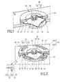
- ein mögliches Ausführungsbeispiel eines erfindungsgemäßen Schalters mit einer Schnappscheibe, einem Deckel und Kontaktflächen, auf denen die Schnappscheibe aufliegt,
- Fig.2
- ein weiteres Ausführungsbeispiel eines Schalters mit Schnappscheibe, Kontaktflächen und Deckel,
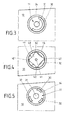
- Fig. 3
- eine Draufsicht auf eine Aufnahme des Schalters, in der die Schnappscheibe gemäß
Figur 1 einsetzbar ist, - Fig. 4
- die Aufnahme gemäß
Figur 3 , in der die Schnappscheibe eingesetzt ist, - Fig. 5
- eine weitere Ausführungsalternative einer Aufnahme gemäß
Figur 3 , - Fig. 6
- der Schalter gemäß
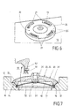
Figur 2 in einer weiteren dreidimensionalen Ansicht - Fig. 7
- ein weiteres Ausführungsbeispiel eines Schalters mit einer Schnappscheibe, Kontaktflächen sowie einem Deckel,
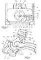
- Fig. 8
- ein weiteres Ausführungsbeispiel eines Schalters mit einer Schnappscheibe, Kontaktflächen sowie einem Deckel und
- Fig. 9
- eine weitere Ansicht auf den Schalter gemäß
Figur 8 . - In allen Ausführungsbeispielen gemäß
Figur 1 bis Figur 9 ist ein erfindungsgemäßer Schalter gezeigt, der in einer Tür, in einer Klappe oder in einem Türgriff eines Kraftfahrzeuges zum Einsatz kommen kann. Der Schalter weist einen Grundkörper 10 auf, der mit einer Aufnahme 11 ausgestaltet ist, in der eine Schnappscheibe 40 eingelegt werden kann. Die Aufnahme 11 weist eine erste 31 und eine zweite Kontaktfläche 32 auf, die inFigur 1 bis Figur 5 zumindest teilweise dargestellt sind. Gemäß den gezeigten Ausführungsbeispielen ist die erste Kontaktfläche 31 mittig in der Aufnahme 11 angeordnet. Die zweite Kontaktfläche 32 hingegen erstreckt sich entlang des Randbereiches der Aufnahme 11 und weist einen definierten Abstand zur ersten Kontaktfläche 31 auf. Hierbei ist die Aufnahme 11 kreisförmig ausgestaltet. Die erste Kontaktfläche 31 ist ebenfalls kreisförmig ausgeführt, wobei die zweite Kontaktfläche 32 sich entlang einer Kreisbahn erstreckt. - Die Schnappscheibe 40 weist gemäß
Figur 1, Figur 2 ,Figur 4 undFigur 7-9 einen gewölbten Bereich 41 auf, der oberhalb der ersten Kontaktfläche 31 liegt. Zudem weist die Schnappscheibe 40 mehrere Auflageelemente 42 auf, wobei die Schnappscheibe 40 sowie die zweite Kontaktfläche 32 derart zueinander geometrisch abgestimmt sind, dass mindestens ein Auflageelement 42 die zweite Kontaktfläche 32 kontaktiert. Hierdurch wird sichergestellt, dass in jeder denkbaren Einbaulage der Schnappscheibe 40 in der Aufnahme 11 eine sichere Funktionsweise des Schalters gewährleistet ist, bei der über eine Betätigung der Schnappscheibe 40 beide Kontaktflächen 31, 32 elektrisch verbunden werden können. Es ist nicht notwendig, während der Herstellung des Schalters, nachdem die Schnappscheibe 40 bereits in der Aufnahme 11 eingelegt ist, die Schnappscheibe 40 bezogen auf die zweite Kontaktfläche 32 nachzujustieren bzw. um eine Achse zu drehen, die senkrecht zur Zeichenebene gemäßFigur 3 oder Figur 4 verläuft und durch die erste Kontaktfläche 31 sich erstreckt. -
Figur 3 zeigt ein mögliches Ausführungsbeispiel für die geometrische Ausgestaltung der zweiten Kontaktfläche 32, die entlang einer Kreisbahn um die erste Kontaktfläche 31 sich erstreckt.Figur 4 zeigt hierzu die Schnappscheibe 40, die in der Aufnahme 11 gemäßFigur 3 eingesetzt ist. Bei diesem Ausführungsbeispiel kontaktieren zwei Auflageelemente 42 die zweite Kontaktfläche 32. Gemäß der Erfindung würde es jedoch ausreichen, wenn die zweite Kontaktfläche 32 lediglich eine Länge, insbesondere eine "Bogenlänge" aufweisen würde, bei der nur ein Auflageelement 42 auf der zweiten Kontaktfläche 32 aufliegen würde, welches explizit nicht dargestellt ist. Das bedeutet, dass die Länge L der Kontaktfläche 32 nach der folgenden Berechnung sich beschreiben lässt: L > arc (α) x r, wobei r der Radius der Kreisbahn ist und α= (360/n)° ist, wobei n die Anzahl der Auflageelemente ist. -
Figur 5 zeigt ein weiteres Ausführungsbeispiel, in dem eine zweite Kontaktfläche 32 vorgesehen ist, die aus drei beabstandeten Einzelkontaktflächen 32 sich zusammensetzt. Selbstverständlich ist es denkbar, dass die Anzahl der Einzelkontaktflächen 32 variieren kann sowie die jeweiligen Längen der Einzelkontaktflächen 32. In Abhängigkeit von der Geometrie der Schnappscheibe 40 sowie den Einzelkontaktflächen 32 kann gewährleistet werden, dass in jeder Lage und Position der Schnappscheibe 40 stets ein Kontakt mit mindestens einem Auflageelement 42 und einer Einzelkontaktfläche 32 gewährleistet ist, welches explizit nicht in den Figuren dargestellt ist. - In
Figur 7 ist schematisch die Aufnahme 11 gezeigt, die einen schräg verlaufenden Wandungsbereich 12 aufweist. Der Wandungsbereich 12 ist trichterförmig ausgeführt. - Hierbei verjüngt sich der Wandungsbereich 12 in Richtung Schnappscheibe 40, die mit ihren Auflageelementen 42 auf der zweiten Kontaktfläche 32 aufliegt. Ein Vorteil eines schräg verlaufenden Wandungsbereiches 12 ist, dass während der Herstellung des Schalters und des Einlegens der Schnappscheibe 40, die Schnappscheibe 40 in die Aufnahme 11 einfach "eingeworfen" werden kann, wobei gleichzeitig der Wandungsbereich 12 dafür sorgt, dass die Schnappscheibe 40 zuverlässig den Weg in die Aufnahme 11 auf die Kontaktflächen 31, 32 findet. Hierbei gleitet die Schnappscheibe 40 mit ihren Auflageelementen 42 entlang des Wandungsbereiches 12, bis die Schnappscheibe 40 in die Aufnahme 11 fällt. Der Wandungsbereich 12 dient somit als Montagehilfe für die Schnappscheibe 40.
- Wie in den
Figuren 1, 2 undFigur 7-9 dargestellt ist, weist der Deckel 20 ein Fußelement 22 auf, das in die Aufnahme 11 hineinragt und die Auflageelemente 42 kontaktiert. Hierdurch wird ein zuverlässiger Halt der Schnappscheibe 40 im eingebauten Zustand erreicht, ohne dass die Gefahr besteht, dass bei einer Betätigung des Schalters ein oder mehrere Auflageelemente 42 sich von dem Kontakt mit der zweiten Kontaktfläche 32 lösen. Hierbei ist das Fußelement 22 umlaufend, ringförmig ausgeführt. - Wie insbesondere in
Figur 1, Figur 2 sowieFigur 7 zu erkennen ist, ist die Aufnahme 11 durch ein Kragenelement 14 des Grundkörpers 10 umfasst. Das Kragenelement 14 stellt hierbei eine Art Wandung dar. InFigur 1 ist ein mögliches Ausführungsbeispiel zur Befestigung des Deckels 20 am Grundkörper 10 dargestellt. Hierbei ist der Deckel 20 laserverschweißt am Kragenelement 14, wodurch eine zuverlässige Abdichtung der gekapselten Aufnahme 11 erzielt wird. Ebenfalls ist es in einem weiteren Ausführungsbeispiel denkbar, dass der Deckel 20 am Kragenelement 14 über eine Klebverbindung befestigt ist. - Gemäß
Figur 2 ,Figur 6 sowieFigur 7-8 ist ein weiteres Ausführungsbeispiel zur Befestigung des Deckels 20 am Grundkörper 10 dargestellt, wobei der Deckel 20 über eine Klipsverbindung am Grundkörper 10 befestigt ist. Hierbei weist der Grundkörper 10 hakenförmige Rastelemente 13 auf, die in Gegenrastelemente 21, insbesondere Öffnungen 21 des Deckels 20 eingreifen und somit eine zuverlässige Befestigung des Deckels 20 am Grundkörper 10 gewährleisten. Um eine zuverlässige Abdichtung des Innenbereiches der Aufnahme 11 zu gewährleisten, weist der Deckel 20 eine Abdichtung 23 auf, die gemäßFigur 2 einen ersten 23.1 und einen zweiten Abdichtungsbereich 23.2 aufweist. Die Abdichtung 23 ist im Querschnitt des Deckels 20 L-förmig ausgestaltet. Hierbei ist der Deckel 20 ein Zwei-Komponenten-Kunststoffteil, wobei die Abdichtung 23 aus einem ersten Kunststoff besteht. Hierbei weist der Deckel 20 einen ersten Bereich 24 auf, der mittig am Deckel 20 angeordnet ist. Der zweite Bereich 25 umfasst den ersten Bereich 24, wobei der zweite Bereich 25 des Deckels 20 härter ist als der erste Bereich 24. Zudem ist der erste Bereich 24 des Deckels 20 mit einem innenliegenden Kontaktelement 26 ausgeführt, der in Richtung des gewölbten Bereiches 41 der Schnappscheibe 40 sich erstreckt. Im Folgenden Ausführungsbeispiel ist der erste Bereich 24 des Deckels 20 aus dem gleichen ersten Kunststoff hergestellt wie die Abdichtung 23. - In
Figur 8 und 9 ist eine weitere Variante eines Ausführungsbeispiels gezeigt, wobei der Deckel 20 ein Zwei-Komponenten-Kunststoffteil ist. Der erste Bereich 24 des Deckels 20 dient hierbei als Taster für die Schnappscheibe 40. Der zweite Bereich 25 des Deckels 20 ist mit einem Gegenrastelement 21 ausgebildet, wobei das Gegenrastelement 21 an seinem freien Ende mit einem Rasthaken 21.1 ausgeführt ist. Im vorliegenden Ausführungsbeispiel weist der Deckel 20 zwei Gegenrastelemente 21 mit jeweils einem Rasthaken 21.1 auf, wobei jedes Gegenrastelement 21 durch ein Rastelement 13 des Grundkörpers 10 hindurchragt. Das Rastelement 13 des Grundkörpers 10 ist als Öffnung ausgebildet, in der das Gegenrastelement 21 des Deckels 20 zuverlässig gehalten ist. Diese Verbindung des Deckels 20 am Grundkörper 10 stellt eine zuverlässige und einfache Rastverbindung dar. Der zweite Bereich 25 des Deckels 20 ist hierbei mit dem härterem zweiten Kunststoff hergestellt, damit eine zuverlässige Fixierung des Deckels 20 am Grundkörper 10 sichergestellt ist. Der erste Bereich 24 des Deckels 20 ist hingegen mit dem ersten Kunststoff ausgeführt, der weicher als der zweite Kunststoff ausgeführt ist. Wie auch in den übrigen Ausführungsbeispielen gemäßFigur 1 bis Figur 7 dient der erste Bereich 24 des Deckels 20 als Taster, um die darunter liegende Schnappscheibe 40 entsprechend zu verformen. - Wie in
Figur 9 deutlich zu erkennen ist, weist der zweite Bereich 25 des Deckels 20 einen Rand 25.1 auf der Unterseite 27 des Deckels 20 auf. Dieser Rand 25.1 weist eine Dichtung 28 auf, die aus dem ersten Kunststoff ausgeführt ist. Hierbei ist der erste Bereich 24 mit der Dichtung 28 materialeinheitlich verbunden. Die erste 31 und die zweite Kontaktfläche 32 sind jeweils ein Bestandteil eines ersten 31A und eines zweiten Kontaktelementes 32A. Hierbei befindet sich die erste 31 und die zweite Kontaktfläche 32 in der Aufnahme 11 des Grundkörpers 10. Das erste und das zweite Kontaktelement 31A, 32A erstrecken sich aus der Aufnahme 11 und verlassen den Deckel 20 an der Stelle, die mit dem Bezugszeichen 29 versehen ist. In einer weiteren Ausführungsalternative, die explizit nicht dargestellt ist, können beide Kontaktelemente 31A und 32A senkrecht zur Zeichenebene gemäßFigur 8 sich erstrecken. Damit der aus zwei Komponenten ausgeführte Deckel 20 gute Haptikeigenschaften sowie eine hohe Langlebigkeit aufweist, sind der erste Bereich 24 und der zweite Bereich 25 mit einer gemeinsamen Kontaktfläche 24.2, 25.2 ausgeführt, die eine treppenartige Geometrie aufweist. - Selbstverständlich ist es denkbar, dass weitere Ausführungsformen einer Schnappscheibe 40 in dieser Erfindung zum Einsatz kommen können, die beispielsweise drei oder mehr als vier Auflageelemente 42 aufweisen können. Ebenfalls ist in dem Erfindungsgedanken mit umfasst, dass die Aufnahme 11 eine geometrische Form annehmen kann, die von der kreisförmigen Ausgestaltung, die in den Ausführungsbeispielen gezeigt ist, abweicht. Auch die Anordnung der ersten 31 und der zweiten Kontaktfläche 32 kann innerhalb der Aufnahme 11 variieren. Um die Langlebigkeit des Schalters zu erhöhen, können die erste 31 und die zweite Kontaktfläche 32 sowie die Schnappscheibe 40, insbesondere der gewölbte Bereich 41 und die Auflageelemente 42 eine Beschichtung aufweisen, die insbesondere mindestens aus Au und/oder Ni und/oder Ag und/oder Sn besteht.
- Ebenfalls ist es denkbar, dass gemäß aller Ausführungsbeispiele der Deckel 20 komplett aus dem weichen Kunststoff besteht, wie der erste Bereich 24.
-
- 10
- Grundkörper
- 11
- Aufnahme
- 12
- Wandungsbereich
- 13
- Rastelement
- 14
- Kragenelement
- 20
- Deckel
- 21
- Gegenrastelement, Öffnung
- 21.1
- Rasthaken
- 22
- Fußelement
- 23
- Abdichtung
- 23.1
- erster Abdichtungsbereich
- 23.2
- zweiter Abdichtungsbereich
- 24
- erster Bereich des Deckels
- 24.2
- Kontaktfläche
- 25
- zweiter Bereich des Deckels
- 25.1
- Rand
- 25.2
- Kontaktfläche
- 26
- innenliegendes Kontaktelement
- 27
- Unterseite
- 28
- Dichtung
- 29
- Position, Ort, Stelle
- 31
- erste Kontaktfläche
- 31A
- erstes Kontaktelement
- 32
- zweite Kontaktfläche
- 32A
- zweites Kontaktelement
- 40
- Schnappscheibe
- 41
- gewölbter Bereich der Schnappscheibe
- 42
- Auflageelement
Claims (16)
- Schalter für eine Tür, eine Klappe oder einen Türgriff eines Kraftfahrzeuges, mit einem Grundkörper (10), der eine Aufnahme (11) aufweist,
einer in der Aufnahme (11) vorgesehenen ersten (31) und einer zweiten Kontaktfläche (32),
einer Schnappscheibe (40), die in der Aufnahme (11) angeordnet ist und einen gewölbten Bereich (41), der oberhalb der ersten Kontaktfläche (31) liegt, und mindestens drei Auflageelemente (42) aufweist, wobei mindestens ein Auflageelement (42) die zweite Kontaktfläche (32) kontaktiert, wobei über eine Betätigung der Schnappscheibe (40) der gewölbte Bereich (41) sich elastisch verformt, sodass eine elektrische Verbindung der beiden Kontaktflächen (31, 32) erzielbar ist und somit ein Schaltsignal erzeugbar ist, wobei
die zweite Kontaktfläche (32), die einen Abstand zur ersten Kontaktfläche (31) aufweist, zumindest bereichsweise um die erste Kontaktfläche (31) innerhalb der Aufnahme (11) sich derart erstreckt, dass in jeder möglichen Position der Schnappscheibe (40) innerhalb der Aufnahme (11) zumindest ein Auflageelement (42) die zweite Kontaktfläche (32) berührt. - Schalter nach Anspruch 1,
dadurch gekennzeichnet,
dass die Aufnahme (11) kreisförmig, oval, quadratisch, rechteckig oder dreieckig ausgestaltet ist. - Schalter nach Anspruch 1 oder 2,
dadurch gekennzeichnet,
dass die erste Kontaktfläche (31) mittig in der Aufnahme (11) angeordnet ist und/oder die zweite Kontaktfläche (32) entlang des Randbereiches der Aufnahme (11) sich erstreckt. - Schalter nach einem der vorhergehenden Ansprüche,
dadurch gekennzeichnet,
dass die Schnappscheibe (40) n Auflageelemente (42) aufweist, wobei jedes Aufnahmeelement (11) in einem Winkel α= (360/n)° zum benachbarten Aufnahmeelement (11) ausgerichtet ist, wobei insbesondere die zweite Kontaktfläche (32) auf einer Kreisbahn sich erstreckt, wobei die Länge L der zweiten Kontaktfläche (32) L > arc (α) x r beträgt, wobei r der Radius der Kreisbahn ist. - Schalter nach einem der vorhergehenden Ansprüche,
dadurch gekennzeichnet,
dass die zweite Kontaktfläche (32) aus zueinander beabstandeten Einzelkontaktflächen sich zusammensetzt und/oder dass die erste (31) und die zweite Kontaktflächen (32) aus Metall sind, insbesondere dass die erste (31) und die zweite Kontaktflächen (32) eine Goldbeschichtung aufweisen. - Schalter nach einem der vorhergehenden Ansprüche,
dadurch gekennzeichnet,
dass die Aufnahme (11) einen schräg verlaufenden Wandungsbereich (12) aufweist, der sich in Richtung Schnappscheibe (40) verjüngt. - Schalter nach einem der vorhergehenden Ansprüche,
dadurch gekennzeichnet,
dass ein Deckel (20) aus Kunststoff, der am Grundkörper (10) befestigt ist, die Aufnahme (11) abdichtend verschließt, wobei insbesondere der Deckel (20) form- und/oder kraft- und/oder stoffschlüssig am Grundkörper (10) befestigt ist und/oder dass der Grundkörper (10) Rastelemente (13) aufweist, die in Gegenrastelemente (21) des Deckels (20) hineinragen. - Schalter nach Anspruch 7,
dadurch gekennzeichnet,
dass der Deckel (20) ein Fußelement (22) aufweist, das in die Aufnahme (11) hineinragt und die Auflageelemente (42) kontaktiert, wodurch eine zuverlässige Fixierung der Schnappscheibe (40) erzielbar ist, wobei insbesondere das Fußelement (22) umlaufend verläuft, insbesondere dass das Fußelement (22) ringförmig ausgestaltet ist. - Schalter nach einem der vorhergehenden Ansprüche,
dadurch gekennzeichnet,
dass der Deckel (20) eine Abdichtung (23) aufweist, die einen ersten (23.1) und einen zweiten Abdichtungsbereich (23.2) aufweist, wobei der erste Abdichtungsbereich (23.1) eine radiale Abdichtung ist und der zweite Abdichtungsbereich (23.2) eine axiale Abdichtung ist, wobei insbesondere in einer Querschnittsansicht des Deckels (20) die Abdichtung (23) L-förmig ist. - Schalter nach einem der vorhergehenden Ansprüche,
dadurch gekennzeichnet,
dass die Aufnahme (11) durch ein Kragenelement (14) des Grundkörpers (10) umfasst ist, wobei der Deckel (20) am Kragenelement (14) aufliegt, wobei insbesondere die Abdichtung (23) das Kragenelement (14) kontaktiert. - Schalter nach einem der vorhergehenden Ansprüche,
dadurch gekennzeichnet,
dass der Deckel (20) ein Zwei-Komponenten-Kunststoffteil ist, wobei ein erster Bereich (24) des Kunststoffteil aus einem ersten Kunststoff hergestellt ist und ein zweiter Bereich (25) des Kunststoffteils aus einem zweiten Kunststoff hergestellt ist, wobei der erste Kunststoff weicher ist als der zweite Kunststoff, wobei insbesondere der erste Bereich (24) des Deckels (20) mit einem innenliegenden Kontaktelement (26) ausgeführt ist, der in Richtung des gewölbten Bereiches (42) der Schnappscheibe (40) sich erstreckt. - Schalter nach Anspruch 11,
dadurch gekennzeichnet,
dass der zweite Bereich (25) des Deckels (20) den ersten Bereich (24) des Deckels (20) umfasst, wobei der zweite Bereich (25) des Deckels (20) am Grundkörper (10) befestigt ist. - Schalter nach einem der vorhergehenden Ansprüche,
dadurch gekennzeichnet,
dass der gewölbte Bereich (41) der Schnappscheibe (40) sowie die Auflageelemente (42) eine Beschichtung aufweisen, insbesondere die Beschichtung mindestens aus Au und/oder Ni und/oder Ag und/oder Sn besteht. - Schalter nach einem der vorhergehenden Ansprüche,
dadurch gekennzeichnet,
dass das Gegenrastelement (21) des Deckels (20) mit einem Rasthaken (21.1) ausgeführt ist, der im Rastelement (13) des Grundkörpers (10) gehalten ist, wobei das Rastelement (13) des Grundkörpers (10) als Öffnung ausgeführt ist und/oder dass der zweite Bereich (25) des Deckels (20) mindestens ein Gegenrastelement (21) aufweist. - Schalter nach einem der vorhergehenden Ansprüche,
dadurch gekennzeichnet,
dass der zweite Bereich (25) des Deckels (20) einen Rand (25.1) auf der Unterseite (27) des Deckels (20) aufweist, wobei der Rand (25.1) eine Dichtung (28) aufweist, die aus dem ersten Kunststoff ausgeführt ist, wobei insbesondere der erste Bereich (24) mit der Dichtung (28) materialeinheitlich verbunden ist. - Schalter nach einem der vorhergehenden Ansprüche,
dadurch gekennzeichnet,
dass die erste (31) und die zweite Kontaktfläche (32) jeweils ein Bestandteil eines ersten (31A) und eines zweiten Kontaktelementes (32A) ist, wobei das erste (31A) und das zweite Kontaktelement (32A) aus der Aufnahme (11) sich erstrecken und/oder der erste Bereich (24) und der zweite Bereich (25) eine gemeinsame Kontaktfläche (24.2,25.2) aufweisen, die insbesondere stufenartig und/oder treppenartig ausgeführt ist.
Applications Claiming Priority (1)
| Application Number | Priority Date | Filing Date | Title |
|---|---|---|---|
| DE102010037551A DE102010037551A1 (de) | 2010-09-15 | 2010-09-15 | Schalter |
Publications (3)
| Publication Number | Publication Date |
|---|---|
| EP2431990A2 true EP2431990A2 (de) | 2012-03-21 |
| EP2431990A3 EP2431990A3 (de) | 2013-03-27 |
| EP2431990B1 EP2431990B1 (de) | 2016-07-20 |
Family
ID=44763886
Family Applications (1)
| Application Number | Title | Priority Date | Filing Date |
|---|---|---|---|
| EP11181325.9A Active EP2431990B1 (de) | 2010-09-15 | 2011-09-15 | Schalter |
Country Status (4)
| Country | Link |
|---|---|
| US (1) | US8598478B2 (de) |
| EP (1) | EP2431990B1 (de) |
| CN (1) | CN102403151B (de) |
| DE (1) | DE102010037551A1 (de) |
Cited By (1)
| Publication number | Priority date | Publication date | Assignee | Title |
|---|---|---|---|---|
| WO2018068777A1 (de) * | 2016-10-13 | 2018-04-19 | Scherdel Marienberg Gmbh | Sitzbelegungssensor |
Families Citing this family (6)
| Publication number | Priority date | Publication date | Assignee | Title |
|---|---|---|---|---|
| US9136071B2 (en) * | 2011-06-10 | 2015-09-15 | International Business Machines Corporation | Overlay for an electrical switch |
| DE102013203466A1 (de) * | 2013-03-01 | 2014-09-04 | Zf Friedrichshafen Ag | Schalter |
| JP6249483B2 (ja) * | 2014-02-05 | 2017-12-20 | アルプス電気株式会社 | プッシュスイッチ |
| JP6892762B2 (ja) * | 2017-02-15 | 2021-06-23 | 信越ポリマー株式会社 | 押釦スイッチ用部材およびその製造方法 |
| CN108052628B (zh) * | 2017-12-19 | 2020-07-14 | 河北省科学院应用数学研究所 | 道岔启动电流检测方法、系统及终端设备 |
| FR3084514B1 (fr) * | 2018-07-25 | 2021-02-26 | C&K Components S A S | Commutateur electrique a effet tactile avec positionnement axial du troncon d'actionnement de l'actionneur souple |
Citations (1)
| Publication number | Priority date | Publication date | Assignee | Title |
|---|---|---|---|---|
| DE102007062907B3 (de) | 2007-12-21 | 2009-03-12 | Kleiner Gmbh | Schnappscheibe |
Family Cites Families (9)
| Publication number | Priority date | Publication date | Assignee | Title |
|---|---|---|---|---|
| DE4139554A1 (de) | 1991-10-14 | 1993-04-15 | Fela Mikrotechnik Ag | Elektrischer tastschalter |
| FR2799570B1 (fr) * | 1999-10-08 | 2001-11-16 | Itt Mfg Enterprises Inc | Commutateur electrique perfectionne a effet tactile a plusieurs voies et a organe de declenchement unique |
| JP2001283690A (ja) * | 2000-03-29 | 2001-10-12 | Hosiden Corp | 多接点入力装置 |
| JP2002216580A (ja) * | 2001-01-18 | 2002-08-02 | Alps Electric Co Ltd | 接点板及び接点板付きシート及びこれを用いたスイッチ装置 |
| DE102004040395A1 (de) | 2003-08-23 | 2005-03-24 | Marquardt Gmbh | Elektrisches Bauelement, insbesondere elektrischer Schalter |
| CN1790576B (zh) * | 2004-11-08 | 2010-12-01 | 株式会社藤仓 | 用于开关的膜片、其制造方法、薄膜开关以及输入设备 |
| DE102005037613A1 (de) | 2005-08-05 | 2007-02-08 | Rafi Gmbh & Co. Kg | Mikroschalter |
| US8111522B2 (en) * | 2008-04-29 | 2012-02-07 | Apple Inc. | Switch structures for use on printed circuit boards |
| JP2010040428A (ja) * | 2008-08-07 | 2010-02-18 | Smk Corp | スイッチ |
-
2010
- 2010-09-15 DE DE102010037551A patent/DE102010037551A1/de not_active Withdrawn
-
2011
- 2011-09-14 US US13/232,933 patent/US8598478B2/en not_active Expired - Fee Related
- 2011-09-14 CN CN201110271356.5A patent/CN102403151B/zh not_active Expired - Fee Related
- 2011-09-15 EP EP11181325.9A patent/EP2431990B1/de active Active
Patent Citations (1)
| Publication number | Priority date | Publication date | Assignee | Title |
|---|---|---|---|---|
| DE102007062907B3 (de) | 2007-12-21 | 2009-03-12 | Kleiner Gmbh | Schnappscheibe |
Cited By (1)
| Publication number | Priority date | Publication date | Assignee | Title |
|---|---|---|---|---|
| WO2018068777A1 (de) * | 2016-10-13 | 2018-04-19 | Scherdel Marienberg Gmbh | Sitzbelegungssensor |
Also Published As
| Publication number | Publication date |
|---|---|
| DE102010037551A9 (de) | 2012-07-05 |
| CN102403151A (zh) | 2012-04-04 |
| US8598478B2 (en) | 2013-12-03 |
| EP2431990B1 (de) | 2016-07-20 |
| US20120061214A1 (en) | 2012-03-15 |
| DE102010037551A1 (de) | 2012-03-15 |
| EP2431990A3 (de) | 2013-03-27 |
| CN102403151B (zh) | 2016-08-10 |
Similar Documents
| Publication | Publication Date | Title |
|---|---|---|
| EP2431990B1 (de) | Schalter | |
| EP0135021B1 (de) | Leuchte | |
| EP1197402A2 (de) | Fahrzeuglenkrad | |
| EP1795990B1 (de) | Bedieneinheit für eine Fahrzeugkomponente | |
| DE102004007390B4 (de) | Verriegelungseinheit für ein bewegliches Schließelement | |
| EP2800117A1 (de) | Betätigungseinheit | |
| DE19954857B4 (de) | Befestigungsvorrichtung für eine Zusatzmatte | |
| DE3629650C2 (de) | ||
| DE2700691C3 (de) | Druckschalter für eine elektronische Uhr | |
| DE4439008C2 (de) | Elektrischer Tastschalter | |
| EP1612103A1 (de) | Spieloptimierte Aufnahme für Schaltstück | |
| DE19514539A1 (de) | Mehrfunktionsschalter, insbesondere Spiegelverstellschalter für ein Kraftfahrzeug | |
| DE102004036117A1 (de) | Thermobimetallschalter | |
| DE19819693A1 (de) | Federschaltelement mit taktiler Rückmeldung | |
| WO2005103856A1 (de) | Dreh- und/oder drucksteller mit joystick | |
| DE10227996A1 (de) | Getriebe-Antriebseinheit mit Rastelement | |
| EP2276045B1 (de) | Elektrischer Schalter | |
| DE102015209984B3 (de) | Gerät mit einem Gehäuse | |
| DE19600387C1 (de) | Zweistufentaster | |
| DE2805597A1 (de) | Drucktastenschalter | |
| EP1808877A2 (de) | Elektrischer Mikro-Schalter | |
| EP3837708B1 (de) | Elektrischer schalter | |
| DE102004040983A1 (de) | Betätigungseinrichtung für einen Staubsauger mit einem angeformten Federelement | |
| DE3932547C1 (en) | Push-button or key switch e.g. for vehicle door opening indication - has plunger held by spring with contact broken by disc | |
| EP0007018A1 (de) | Kupplungsausrücker, insbesondere für Kraftfahrzeugkupplungen |
Legal Events
| Date | Code | Title | Description |
|---|---|---|---|
| PUAI | Public reference made under article 153(3) epc to a published international application that has entered the european phase |
Free format text: ORIGINAL CODE: 0009012 |
|
| AK | Designated contracting states |
Kind code of ref document: A2 Designated state(s): AL AT BE BG CH CY CZ DE DK EE ES FI FR GB GR HR HU IE IS IT LI LT LU LV MC MK MT NL NO PL PT RO RS SE SI SK SM TR |
|
| AX | Request for extension of the european patent |
Extension state: BA ME |
|
| PUAL | Search report despatched |
Free format text: ORIGINAL CODE: 0009013 |
|
| AK | Designated contracting states |
Kind code of ref document: A3 Designated state(s): AL AT BE BG CH CY CZ DE DK EE ES FI FR GB GR HR HU IE IS IT LI LT LU LV MC MK MT NL NO PL PT RO RS SE SI SK SM TR |
|
| AX | Request for extension of the european patent |
Extension state: BA ME |
|
| RIC1 | Information provided on ipc code assigned before grant |
Ipc: H01H 13/18 20060101ALI20130221BHEP Ipc: H01H 13/48 20060101AFI20130221BHEP Ipc: H01H 3/16 20060101ALI20130221BHEP |
|
| 17P | Request for examination filed |
Effective date: 20130927 |
|
| RAX | Requested extension states of the european patent have changed |
Extension state: BA Payment date: 20130927 Extension state: ME Payment date: 20130927 |
|
| RBV | Designated contracting states (corrected) |
Designated state(s): AL AT BE BG CH CY CZ DE DK EE ES FI FR GB GR HR HU IE IS IT LI LT LU LV MC MK MT NL NO PL PT RO RS SE SI SK SM TR |
|
| DAX | Request for extension of the european patent (deleted) | ||
| GRAP | Despatch of communication of intention to grant a patent |
Free format text: ORIGINAL CODE: EPIDOSNIGR1 |
|
| INTG | Intention to grant announced |
Effective date: 20151016 |
|
| INTG | Intention to grant announced |
Effective date: 20160303 |
|
| GRAS | Grant fee paid |
Free format text: ORIGINAL CODE: EPIDOSNIGR3 |
|
| GRAA | (expected) grant |
Free format text: ORIGINAL CODE: 0009210 |
|
| AK | Designated contracting states |
Kind code of ref document: B1 Designated state(s): AL AT BE BG CH CY CZ DE DK EE ES FI FR GB GR HR HU IE IS IT LI LT LU LV MC MK MT NL NO PL PT RO RS SE SI SK SM TR |
|
| REG | Reference to a national code |
Ref country code: GB Ref legal event code: FG4D Free format text: NOT ENGLISH |
|
| REG | Reference to a national code |
Ref country code: CH Ref legal event code: EP |
|
| REG | Reference to a national code |
Ref country code: IE Ref legal event code: FG4D Free format text: LANGUAGE OF EP DOCUMENT: GERMAN |
|
| REG | Reference to a national code |
Ref country code: AT Ref legal event code: REF Ref document number: 814669 Country of ref document: AT Kind code of ref document: T Effective date: 20160815 |
|
| REG | Reference to a national code |
Ref country code: DE Ref legal event code: R096 Ref document number: 502011010192 Country of ref document: DE |
|
| REG | Reference to a national code |
Ref country code: LT Ref legal event code: MG4D |
|
| REG | Reference to a national code |
Ref country code: NL Ref legal event code: MP Effective date: 20160720 |
|
| PG25 | Lapsed in a contracting state [announced via postgrant information from national office to epo] |
Ref country code: NL Free format text: LAPSE BECAUSE OF FAILURE TO SUBMIT A TRANSLATION OF THE DESCRIPTION OR TO PAY THE FEE WITHIN THE PRESCRIBED TIME-LIMIT Effective date: 20160720 Ref country code: LT Free format text: LAPSE BECAUSE OF FAILURE TO SUBMIT A TRANSLATION OF THE DESCRIPTION OR TO PAY THE FEE WITHIN THE PRESCRIBED TIME-LIMIT Effective date: 20160720 Ref country code: RS Free format text: LAPSE BECAUSE OF FAILURE TO SUBMIT A TRANSLATION OF THE DESCRIPTION OR TO PAY THE FEE WITHIN THE PRESCRIBED TIME-LIMIT Effective date: 20160720 Ref country code: IS Free format text: LAPSE BECAUSE OF FAILURE TO SUBMIT A TRANSLATION OF THE DESCRIPTION OR TO PAY THE FEE WITHIN THE PRESCRIBED TIME-LIMIT Effective date: 20161120 Ref country code: HR Free format text: LAPSE BECAUSE OF FAILURE TO SUBMIT A TRANSLATION OF THE DESCRIPTION OR TO PAY THE FEE WITHIN THE PRESCRIBED TIME-LIMIT Effective date: 20160720 Ref country code: NO Free format text: LAPSE BECAUSE OF FAILURE TO SUBMIT A TRANSLATION OF THE DESCRIPTION OR TO PAY THE FEE WITHIN THE PRESCRIBED TIME-LIMIT Effective date: 20161020 Ref country code: IT Free format text: LAPSE BECAUSE OF FAILURE TO SUBMIT A TRANSLATION OF THE DESCRIPTION OR TO PAY THE FEE WITHIN THE PRESCRIBED TIME-LIMIT Effective date: 20160720 Ref country code: FI Free format text: LAPSE BECAUSE OF FAILURE TO SUBMIT A TRANSLATION OF THE DESCRIPTION OR TO PAY THE FEE WITHIN THE PRESCRIBED TIME-LIMIT Effective date: 20160720 |
|
| PG25 | Lapsed in a contracting state [announced via postgrant information from national office to epo] |
Ref country code: PL Free format text: LAPSE BECAUSE OF FAILURE TO SUBMIT A TRANSLATION OF THE DESCRIPTION OR TO PAY THE FEE WITHIN THE PRESCRIBED TIME-LIMIT Effective date: 20160720 Ref country code: LV Free format text: LAPSE BECAUSE OF FAILURE TO SUBMIT A TRANSLATION OF THE DESCRIPTION OR TO PAY THE FEE WITHIN THE PRESCRIBED TIME-LIMIT Effective date: 20160720 Ref country code: PT Free format text: LAPSE BECAUSE OF FAILURE TO SUBMIT A TRANSLATION OF THE DESCRIPTION OR TO PAY THE FEE WITHIN THE PRESCRIBED TIME-LIMIT Effective date: 20161121 Ref country code: ES Free format text: LAPSE BECAUSE OF FAILURE TO SUBMIT A TRANSLATION OF THE DESCRIPTION OR TO PAY THE FEE WITHIN THE PRESCRIBED TIME-LIMIT Effective date: 20160720 Ref country code: SE Free format text: LAPSE BECAUSE OF FAILURE TO SUBMIT A TRANSLATION OF THE DESCRIPTION OR TO PAY THE FEE WITHIN THE PRESCRIBED TIME-LIMIT Effective date: 20160720 Ref country code: BE Free format text: LAPSE BECAUSE OF NON-PAYMENT OF DUE FEES Effective date: 20160930 Ref country code: GR Free format text: LAPSE BECAUSE OF FAILURE TO SUBMIT A TRANSLATION OF THE DESCRIPTION OR TO PAY THE FEE WITHIN THE PRESCRIBED TIME-LIMIT Effective date: 20161021 |
|
| REG | Reference to a national code |
Ref country code: DE Ref legal event code: R097 Ref document number: 502011010192 Country of ref document: DE |
|
| PG25 | Lapsed in a contracting state [announced via postgrant information from national office to epo] |
Ref country code: RO Free format text: LAPSE BECAUSE OF FAILURE TO SUBMIT A TRANSLATION OF THE DESCRIPTION OR TO PAY THE FEE WITHIN THE PRESCRIBED TIME-LIMIT Effective date: 20160720 Ref country code: MC Free format text: LAPSE BECAUSE OF FAILURE TO SUBMIT A TRANSLATION OF THE DESCRIPTION OR TO PAY THE FEE WITHIN THE PRESCRIBED TIME-LIMIT Effective date: 20160720 Ref country code: EE Free format text: LAPSE BECAUSE OF FAILURE TO SUBMIT A TRANSLATION OF THE DESCRIPTION OR TO PAY THE FEE WITHIN THE PRESCRIBED TIME-LIMIT Effective date: 20160720 |
|
| REG | Reference to a national code |
Ref country code: CH Ref legal event code: PL |
|
| PLBE | No opposition filed within time limit |
Free format text: ORIGINAL CODE: 0009261 |
|
| STAA | Information on the status of an ep patent application or granted ep patent |
Free format text: STATUS: NO OPPOSITION FILED WITHIN TIME LIMIT |
|
| PG25 | Lapsed in a contracting state [announced via postgrant information from national office to epo] |
Ref country code: DK Free format text: LAPSE BECAUSE OF FAILURE TO SUBMIT A TRANSLATION OF THE DESCRIPTION OR TO PAY THE FEE WITHIN THE PRESCRIBED TIME-LIMIT Effective date: 20160720 Ref country code: BG Free format text: LAPSE BECAUSE OF FAILURE TO SUBMIT A TRANSLATION OF THE DESCRIPTION OR TO PAY THE FEE WITHIN THE PRESCRIBED TIME-LIMIT Effective date: 20161020 Ref country code: CZ Free format text: LAPSE BECAUSE OF FAILURE TO SUBMIT A TRANSLATION OF THE DESCRIPTION OR TO PAY THE FEE WITHIN THE PRESCRIBED TIME-LIMIT Effective date: 20160720 Ref country code: SK Free format text: LAPSE BECAUSE OF FAILURE TO SUBMIT A TRANSLATION OF THE DESCRIPTION OR TO PAY THE FEE WITHIN THE PRESCRIBED TIME-LIMIT Effective date: 20160720 Ref country code: SM Free format text: LAPSE BECAUSE OF FAILURE TO SUBMIT A TRANSLATION OF THE DESCRIPTION OR TO PAY THE FEE WITHIN THE PRESCRIBED TIME-LIMIT Effective date: 20160720 |
|
| 26N | No opposition filed |
Effective date: 20170421 |
|
| GBPC | Gb: european patent ceased through non-payment of renewal fee |
Effective date: 20161020 |
|
| REG | Reference to a national code |
Ref country code: IE Ref legal event code: MM4A |
|
| REG | Reference to a national code |
Ref country code: FR Ref legal event code: ST Effective date: 20170531 |
|
| PG25 | Lapsed in a contracting state [announced via postgrant information from national office to epo] |
Ref country code: FR Free format text: LAPSE BECAUSE OF NON-PAYMENT OF DUE FEES Effective date: 20160930 Ref country code: CH Free format text: LAPSE BECAUSE OF NON-PAYMENT OF DUE FEES Effective date: 20160930 Ref country code: IE Free format text: LAPSE BECAUSE OF NON-PAYMENT OF DUE FEES Effective date: 20160915 Ref country code: LI Free format text: LAPSE BECAUSE OF NON-PAYMENT OF DUE FEES Effective date: 20160930 Ref country code: GB Free format text: LAPSE BECAUSE OF NON-PAYMENT OF DUE FEES Effective date: 20161020 |
|
| PG25 | Lapsed in a contracting state [announced via postgrant information from national office to epo] |
Ref country code: LU Free format text: LAPSE BECAUSE OF NON-PAYMENT OF DUE FEES Effective date: 20160915 Ref country code: SI Free format text: LAPSE BECAUSE OF FAILURE TO SUBMIT A TRANSLATION OF THE DESCRIPTION OR TO PAY THE FEE WITHIN THE PRESCRIBED TIME-LIMIT Effective date: 20160720 |
|
| REG | Reference to a national code |
Ref country code: AT Ref legal event code: MM01 Ref document number: 814669 Country of ref document: AT Kind code of ref document: T Effective date: 20160915 |
|
| REG | Reference to a national code |
Ref country code: BE Ref legal event code: MM Effective date: 20160930 |
|
| PG25 | Lapsed in a contracting state [announced via postgrant information from national office to epo] |
Ref country code: AT Free format text: LAPSE BECAUSE OF NON-PAYMENT OF DUE FEES Effective date: 20160915 |
|
| PG25 | Lapsed in a contracting state [announced via postgrant information from national office to epo] |
Ref country code: CY Free format text: LAPSE BECAUSE OF FAILURE TO SUBMIT A TRANSLATION OF THE DESCRIPTION OR TO PAY THE FEE WITHIN THE PRESCRIBED TIME-LIMIT Effective date: 20160720 Ref country code: HU Free format text: LAPSE BECAUSE OF FAILURE TO SUBMIT A TRANSLATION OF THE DESCRIPTION OR TO PAY THE FEE WITHIN THE PRESCRIBED TIME-LIMIT; INVALID AB INITIO Effective date: 20110915 |
|
| PG25 | Lapsed in a contracting state [announced via postgrant information from national office to epo] |
Ref country code: MT Free format text: LAPSE BECAUSE OF FAILURE TO SUBMIT A TRANSLATION OF THE DESCRIPTION OR TO PAY THE FEE WITHIN THE PRESCRIBED TIME-LIMIT Effective date: 20160720 Ref country code: MK Free format text: LAPSE BECAUSE OF FAILURE TO SUBMIT A TRANSLATION OF THE DESCRIPTION OR TO PAY THE FEE WITHIN THE PRESCRIBED TIME-LIMIT Effective date: 20160720 Ref country code: TR Free format text: LAPSE BECAUSE OF FAILURE TO SUBMIT A TRANSLATION OF THE DESCRIPTION OR TO PAY THE FEE WITHIN THE PRESCRIBED TIME-LIMIT Effective date: 20160720 |
|
| PG25 | Lapsed in a contracting state [announced via postgrant information from national office to epo] |
Ref country code: AL Free format text: LAPSE BECAUSE OF FAILURE TO SUBMIT A TRANSLATION OF THE DESCRIPTION OR TO PAY THE FEE WITHIN THE PRESCRIBED TIME-LIMIT Effective date: 20160720 |
|
| P01 | Opt-out of the competence of the unified patent court (upc) registered |
Effective date: 20230425 |
|
| PGFP | Annual fee paid to national office [announced via postgrant information from national office to epo] |
Ref country code: DE Payment date: 20250930 Year of fee payment: 15 |