EP2431838A2 - Speichermedium, Vorhersagevorrichtung und Vorhersageverfahren - Google Patents
Speichermedium, Vorhersagevorrichtung und Vorhersageverfahren Download PDFInfo
- Publication number
- EP2431838A2 EP2431838A2 EP11179277A EP11179277A EP2431838A2 EP 2431838 A2 EP2431838 A2 EP 2431838A2 EP 11179277 A EP11179277 A EP 11179277A EP 11179277 A EP11179277 A EP 11179277A EP 2431838 A2 EP2431838 A2 EP 2431838A2
- Authority
- EP
- European Patent Office
- Prior art keywords
- predicting
- fan
- revolution frequency
- flow rate
- rotated
- Prior art date
- Legal status (The legal status is an assumption and is not a legal conclusion. Google has not performed a legal analysis and makes no representation as to the accuracy of the status listed.)
- Withdrawn
Links
Images


Classifications
-
- G—PHYSICS
- G06—COMPUTING OR CALCULATING; COUNTING
- G06F—ELECTRIC DIGITAL DATA PROCESSING
- G06F1/00—Details not covered by groups G06F3/00 - G06F13/00 and G06F21/00
- G06F1/16—Constructional details or arrangements
- G06F1/20—Cooling means
- G06F1/206—Cooling means comprising thermal management
-
- H—ELECTRICITY
- H05—ELECTRIC TECHNIQUES NOT OTHERWISE PROVIDED FOR
- H05K—PRINTED CIRCUITS; CASINGS OR CONSTRUCTIONAL DETAILS OF ELECTRIC APPARATUS; MANUFACTURE OF ASSEMBLAGES OF ELECTRICAL COMPONENTS
- H05K7/00—Constructional details common to different types of electric apparatus
- H05K7/20—Modifications to facilitate cooling, ventilating, or heating
- H05K7/20009—Modifications to facilitate cooling, ventilating, or heating using a gaseous coolant in electronic enclosures
- H05K7/20209—Thermal management, e.g. fan control
Definitions
- the embodiments discussed herein are directed to a storage medium, a predicting apparatus, and a predicting method.
- fans for cooling electronic components in the electronic devices.
- the fans installed in electronic devices suppress heating of the electronic components caused by operations of the electronic devices or a surrounding environment, for example. Therefore, fans can prevent failure of electronic devices due to overheating, and prevent potential burn injury and other accidents of a user who might touch the overheated electronic devices.
- a noise is predicted based on a sound pressure level at a position one meter away from the air-suctioning side of the fan being rotated at unloaded and rated revolution frequencies, which are provided by the manufacture of the fan and the like.
- a prediction is made based on a loaded noise at an operating point.
- a thermal analysis is applied to predict a pressure difference between the front and the rear sides of a fan at an operating point, and a loaded noise and a flow rate at the operating point are predicted based on the loaded noise, the PQ characteristics, and other factors of the fan.
- a loaded noise of a fan is a sound pressure level with a load applied to the ventilation channel of the fan.
- PQ characteristics represent the pressure difference between the front and the rear sides of each fan, that is, a relationship between the static pressure (P) and the flow rate (Q) of the air caused to flow through the ventilation channel when the fan is rotated.
- a related-art example is described in Japanese Laid-open Patent Publication No. 2001-108642 .
- the loaded noise and the flow rate of a fan it is desirable for the loaded noise and the flow rate of a fan to satisfy respective target conditions.
- reduction in the revolution frequency of a fan lowers a loaded noise of the fan but also lowers the flow rate of the fan.
- Increasing the revolution frequency of a fan boosts the flow rate but also involves increased loaded noise of the fan. In this manner, a loaded noise and a flow rate of a fan are in a trade-off relationship upon satisfying their target conditions.
- a prediction can be made as to whether a fan can satisfy both target conditions of the loaded noise and the flow rate, which are in such a trade-off relationship, and the prediction results can be used in designing an electronic device in which the fan is installed.
- the following approach is possible. For example, it is possible to actually measure the loaded noise and the PQ characteristics at every typical revolution frequency of the fan, to store the actual measurements in an associated manner, and to use the actual measurements in predicting a loaded noise and a flow rate.
- a computer readable non-transitory storage medium storing a predicting program causes a computer to execute obtaining an actual measurement of data about a fan being rotated at a predetermined revolution frequency; and predicting data about the fan to be rotated at a revolution frequency that is different from the predetermined revolution frequency based on the actual measurement of the data thus obtained.
- a non-transitory storage medium storing a predicting program causes a computer to execute predicting a first revolution frequency that is a revolution frequency of a fan at which a sound pressure level of sound caused by rotations of the fan satisfies a condition represented as a predetermined target sound volume based on an actual measurement of a sound pressure level of sound caused by rotations of the fan being rotated at a predetermined revolution frequency and the target sound volume; and predicting a first flow rate that is a flow rate of air to be caused to flow through a ventilation channel by the fan to be rotated at the first revolution frequency thus predicted based on the first revolution frequency thus predicted, an actual measurement of a characteristic related to a static pressure and a flow rate of the fan being rotated at the predetermined revolution frequency, and a pressure loss characteristic of the ventilation channel of the fan.
- a predicting apparatus includes an obtaining unit that obtains an actual measurement of data about a fan being rotated at a predetermined revolution frequency; and a predicting unit that predicts data about the fan to be rotated at a revolution frequency that is different from the predetermined revolution frequency based on the actual measurement of the data thus obtained.
- a predicting apparatus includes a revolution frequency predicting unit that predicts a first revolution frequency that is a revolution frequency of a fan at which a sound pressure level of sound caused by rotations of the fan satisfies a condition represented as a predetermined target sound volume based on an actual measurement of a sound pressure level of sound caused by rotations of the fan being rotated at a predetermined revolution frequency and the target sound volume; a flow rate predicting unit that predicts a first flow rate that is a flow rate of air to be caused to flow through a ventilation channel by the fan to be rotated at the first revolution frequency predicted by the revolution frequency predicting unit based on the first revolution frequency predicted by the revolution frequency predicting unit, an actual measurement of a characteristic related to a static pressure and a flow rate of the fan being rotated at the predetermined revolution frequency, and a pressure loss characteristic of the ventilation channel of the fan.
- a predicting method executed by a predicting unit included in a predicting apparatus includes obtaining an actual measurement of data about a fan being rotated at a predetermined revolution frequency; and predicting data about the fan to be rotated at a revolution frequency that is different from the predetermined revolution frequency based on the actual measurement of the data thus obtained.
- a predicting method includes predicting at which a revolution frequency predicting unit included in a predicting apparatus predicts a first revolution frequency that is a revolution frequency of a fan at which a sound pressure level of sound caused by rotations of the fan satisfies a condition represented as a predetermined target sound volume based on an actual measurement of a sound pressure level of sound caused by rotations of the fan being rotated at a predetermined revolution frequency and the target sound volume; and predicting at which a flow rate predicting unit included in the predicting apparatus predicts a first flow rate that is a flow rate of air to be caused to flow in a ventilation channel by the fan to be rotated at the first revolution frequency predicted by the revolution frequency predicting unit based on the first revolution frequency predicted by the revolution frequency predicting unit, an actual measurement of a characteristic related to a static pressure and a flow rate of the fan being rotated at the predetermined revolution frequency, and a pressure loss characteristic of the ventilation channel of the fan.
- FIG. 1 is a schematic of an exemplary structure of the predicting apparatus according to the first embodiment.
- a predicting apparatus 100 includes, for example, a storage unit 110 and a control unit 120.
- the predicting apparatus 100 is also connected to an input unit 130 and an output unit 140.
- the input unit 130 receives external inputs of information.
- the input unit 130 receives various types of information, e.g., an instruction from a user, and inputs received information, e.g., the instruction, to the control unit 110.
- the instruction is an instruction for executing a "predicting process" to be explained later in detail.
- the instruction for executing the predicting process contains a revolution frequency N' [rpm] of the fan.
- the revolution frequency N' contained in the instruction for executing the predicting process input by the user via the input unit 130 is a revolution frequency that is different from a revolution frequency N of the fan used in actually collecting actual measurements 111 which are to be described later.
- the input unit 130 is, for example, an input device such as a mouse and a keyboard.
- the output unit 140 outputs information externally.
- the output unit 140 receives information such as a prediction result, which is to be described later, from a predicting unit 122.
- the output unit 140 outputs received information such as the prediction result.
- the output unit 140 is, for example, a displaying device such as a display. If this is the case, the information such as the prediction result is displayed on the display.
- the output unit 140 may also be an audio output device such as a speaker, for example. If this is the case, the information such as the prediction result is output from the speaker as a voice.
- the output unit 140 may also output the information such as the prediction result to an external device by means of communications.
- the storage unit 110 stores therein data used in various processes performed by the control unit 120, and results of the various processes performed by the control unit 120.
- the storage unit 110 also stores therein the actual measurements 111 to be described later.
- the storage unit 110 is, for example, a semiconductor memory element such as a random access memory (RAM), a read only memory (ROM), and a flash memory, or a storage device such as a hard disk and an optical disk.
- the actual measurements 111 are actual measurements of a sound pressure level Lp [dB], PQ characteristics, and a fan power [W] that are actually measured while the fan is rotated at a predetermined revolution frequency.
- FIG. 2 is a schematic of an example of the actual measurements. The example illustrated in FIG. 2 depicts the sound pressure level Lp [dB], the PQ characteristics, and the fan power w [W] that are actually measured while the fan is rotated at a revolution frequency N [rpm].
- the control unit 120 includes an internal memory for storing therein control programs, computer programs specifying various process procedures, and used data.
- the control unit 120 controls the entire predicting apparatus 100.
- the control unit 120 also includes an obtaining unit 121 and the predicting unit 122.
- the control unit 120 is, for example, an integrated circuit such as an application specific integrated circuit (ASIC) and a field programmable gate array (FPGA), or an electronic circuit such as a central processing unit (CPU) and a micro processing unit (MPU).
- ASIC application specific integrated circuit
- FPGA field programmable gate array
- CPU central processing unit
- MPU micro processing unit
- the obtaining unit 121 obtains the actual measurements. For example, the obtaining unit 121 obtains actual measurements 111 from the storage unit 110.
- Equation (2) six is used as a multiplier. However, a value near 5.5 to 6.0 may also be used as a multiplier.
- the multiplier changes depending on factors such as a fan type and a wind speed. Therefore, when a precise prediction is expected, it is preferable to obtain an appropriate multiplier in advance for a specific fan by means of experiments, for example. The same can be said for the PQ characteristics and the fan power.
- the revolution frequency N' of the fan is a value contained in the instruction for executing a predicting process.
- the predicting unit 122 then predicts the PQ characteristics when the fan is to be rotated at the revolution frequency N' based on the actual measurements of the PQ characteristics measured when the fan is rotated at the predetermined revolution frequency N and obtained by the obtaining unit 121.
- FIG. 3 is a schematic for explaining how the PQ characteristics are predicted.
- the example illustrated in FIG. 3 depicts an actual measurement 50 of the PQ characteristics collected where the fan is rotated at the predetermined revolution frequency N, with the horizontal axis representing the flow rate Q [m 3 /min] and the vertical axis representing the static pressure P [Pa].
- the predicting unit 122 selects a plurality of pairs of a flow rate and a static pressure (Q, P) from the actual measurement 50 of the PQ characteristics.
- Q i ⁇ ⁇ Q i ⁇ N ⁇ + N
- the predicting unit 122 then applies interpolation to each pair (Q i ', P i ') of the flow rate Q i ' and the static pressures P i ' to predict the PQ characteristics with the fan being rotated at the revolution frequency N',
- FIG. 3 depicts a prediction 52 of the PQ characteristics with the fan being rotated at the revolution frequency N'.
- the revolution frequency N' is a value smaller than the revolution frequency N.
- FIG. 3 also depicts a prediction 54 of the PQ characteristics with the fan being rotated at a revolution frequency N'' that is a frequency lower than the revolution frequency N'. As illustrated in FIG. 3 , the lower the revolution frequency, the lower the static pressure becomes at the same flow rate.
- the predicting unit 122 then outputs the sound pressure level LpN', the PQ characteristics, and the fan power w' with the fan being rotated at the revolution frequency N', and the revolution frequency N' to the output unit 140. In this manner, the output unit outputs an output result and the like.
- FIG. 4 is a schematic of an example of the output result of the output unit. The sound pressure level LpN', the PQ characteristics, and the fan power w' thus predicted, and the revolution frequency N' of the fan used in the prediction are displayed as illustrated in FIG. 4 .
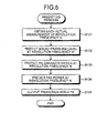
- FIG. 5 is a flowchart of an example of a flow of the predicting process according to the first embodiment.
- the predicting process illustrated in FIG. 5 is started when the instruction for executing the predicting precess is input via the input unit 130.
- the obtaining unit 121 obtains the actual measurements 111 from the storage unit 110 (Step S101).
- the predicting unit 122 then predicts the sound pressure level LpN' [dB] with the fan being rotated at the revolution frequency N' based on the actual measurements 111 (Step S102).
- the predicting unit 122 then predicts the PQ characteristics with the fan being rotated at the revolution frequency N' based on the actual measurements 111 (Step S103).
- the predicting unit 122 then predicts the fan power w' [W] with the fan being rotated at the revolution frequency N' based on the actual measurements 111 (Step S104).
- the predicting unit 122 then outputs the sound pressure level LpN', the PQ characteristics, and the fan power w' thus predicted, and the revolution frequency N' to the output unit 140 (Step S105), and ends the process.
- the predicting apparatus 100 obtains the actual measurements 111 of the data about the fan being rotated at the predetermined revolution frequency N [rpm]. The predicting apparatus 100 then predicts the data about the fan with the fan being rotated at a revolution frequency N' that is different from the predetermined revolution frequency N, based on the actual measurements of the data thus obtained. In this manner, the predicting apparatus 100 according to the first embodiment predicts data about a fan to be rotated at a revolution frequency using the actual measurements of data about a fan measured while being rotated at another revolution frequency. Therefore, the predicting apparatus 100 according to the first embodiment can predict data about a fan using actual measurements collected in a smaller number of hours than that spent in conventional technologies.
- the predicting apparatus according to the second embodiment predicts a revolution frequency, a flow rate, and a sound volume of a fan based on the actual measurements 111.
- FIG, 6 is a schematic of an exemplary structure of the predicting apparatus according to the second embodiment.
- a predicting apparatus 200 includes the storage unit 110 and a control unit 220.
- the control unit 220 is different in having each of the elements described below in replace of the obtaining unit 121 and the predicting unit 122 according to the first embodiment. That is, the control unit 220 includes a revolution frequency predicting unit 221, a flow rate predicting unit 222, a target flow rate achieving revolution frequency predicting unit 223, and a sound volume predicting unit 224.
- each of the elements achieving the same function as that according to the first embodiment is given the same reference numeral as that in FIG. 1 , and an explanation thereof will be omitted hereunder.
- the revolution frequency predicting unit 221 predicts a revolution frequency of a fan that satisfies a condition represented as a target sound volume based on the actual measurements 111.
- a revolution frequency "that satisfies a condition represented as a target sound volume” herein means a revolution frequency at which the sound pressure level of sound attributable to rotations of the fan becomes equal to or less than or less than a sound pressure level represented as a target sound volume.
- the revolution frequency predicting unit 221 then converts the actual measurement of the sound pressure level Lp [dB] to a sound intensity Lp' [W/m 2 ] based on Equation (1) above.
- the flow rate predicting unit 222 predicts a flow rate of the air caused to flow through the ventilation channel by the fan being rotated at the revolution frequency Ns' that is predicted by the revolution frequency predicting unit 221. For example, the flow rate predicting unit 222 obtains a coefficient k of a pressure loss curve stored in the storage unit 110.
- the flow rate predicting unit 222 uses the intersection between the pressure loss curve and the curve of the actual measurement 50 of the PQ characteristics as an operating point, and predicts the flow rate at the operating point as a flow rate with the fan being rotated at the revolution frequency Ns'.
- the flow rate predicting unit 222 predicts the flow rate to be 4.5 [m 3 /min].
- the target flow rate achieving revolution frequency predicting unit 223 predicts a revolution frequency of the fan that satisfies a condition represented as a target flow rate.
- a revolution frequency "that satisfies a condition represented as a target flow rate” herein means a revolution frequency at which the flow rate of the air caused by rotations of the fan to flow through the ventilation channel becomes equal to or higher than the target flow rate, or higher than the target flow rate.
- the target flow rate achieving revolution frequency predicting unit 223 also determines whether the value of the coefficient k for the pressure loss curve can be changed.
- a determining flag which is established in advance in the storage unit 110, is set to a predetermined value, and the target flow rate achieving revolution frequency predicting unit 223 determines whether the value of the coefficient k can be changed by referring to the determining flag.
- the target flow rate achieving revolution frequency predicting unit 223 repeats changing the value of the coefficient k and predicting the revolution frequency N q until the value of the coefficient k exceeds a predetermined changeable range, or until when the sound pressure level predicted by the sound volume predicting unit 224, which is to be described later, satisfies the condition represented as the target sound volume.
- the sound volume predicting unit 224 predicts a sound pressure level with the fan being rotated at the revolution frequency N q satisfying the condition represented as a target flow rate. For example, to begin with, the sound volume predicting unit 224 detects a sound pressure level Lpq corresponding to the flow rate Q d at the operating point that is the intersection between the pressure loss curve and the curve of the actual measurement 50 of the PQ characteristics.
- a detection method of the sound pressure level will now be explained with reference to FIG. 7.
- FIG. 7 is a schematic for explaining an example of how the sound pressure level is detected.
- the flow rate at the operating point 58 that is the intersection between the pressure loss curve 56 and the curve of the actual measurement 50 of the PQ characteristics is 6.0 [m 3 /min].
- an actual measurement 70 of the sound pressure level corresponding to the flow rate of 6.0 [m 3 /min] at the operating point 58 is 50.00 [dBA].
- the sound volume predicting unit 224 detects the sound pressure level corresponding to the flow rate at the operating point as 50.00 [dBA].
- FIGS. 8 and 9 are a flowchart of an example of the predicting process according to the second embodiment.
- the predicting process illustrated in FIGS. 8 and 9 is started when the instruction for executing the predicting process is input via the input unit 130.
- the revolution frequency predicting unit 221 obtains the actual measurements 111 from the storage unit 110 (Step S202). The revolution frequency predicting unit 221 then predicts the revolution frequency Ns' of the fan that satisfies the condition represented as the target sound volume (Step S203).
- the flow rate predicting unit 222 then obtains the coefficient k of the pressure loss curve (Step S204). The flow rate predicting unit 222 then predicts the flow rate of the air caused to flow through the ventilation channel by the fan to be rotated at the revolution frequency Ns' predicted by the revolution frequency predicting unit 221 (Step S205).
- the flow rate predicting unit 222 determines whether the flow rate predicted at Step B205 is equal to or lower than the target flow rate (Step S206). If the flow rate predicted at Step S205 is not equal to or lower than the target flow rate (NO at Step S206), the flow rate predicting unit 222 determines that both of the conditions represented as the target sound volume and the target flow rate can be satisfied, and performs the process below. That is, the flow rate predicting unit 222 outputs the revolution frequency Ns' of the fan and flow rate thus predicted to the output unit 140 (Step S207), and ends the process.
- the target flow rate achieving revolution frequency predicting unit 223 further determines whether the value of the coefficient k can be changed (Step S208). If the value of the coefficient k cannot be changed (NO at Step S208), the target flow rate achieving revolution frequency predicting unit 223 predicts the revolution frequency N q of the fan that satisfies the condition represented as the target flow rate (Step S209). The sound volume predicting unit 224 then predicts the sound pressure level when the fan is rotated at the revolution frequency N q satisfying the condition represented as the target flow rate (Step S210), outputs the results predicted up to this point (Step S207), and ends the process.
- the target flow rate achieving revolution frequency predicting unit 223 calculates the sound volume corresponding to the flow rate at the operating point with the coefficient k incremented by 0.01 (Step S211). The target flow rate achieving revolution frequency predicting unit 223 then calculates the sound volume corresponding to the flow rate at the operating point with the coefficient k decremented by 0.01 (Step S212).
- the target flow rate achieving revolution frequency predicting unit 223 determines whether the sound volume calculated at Step S212 is lower than the sound volume calculated at Step S211 (Step S213). If the sound volume calculated at Step S212 is higher than the sound volume calculated at Step S211, or both of the sound volumes are equal (NO at Step S213), the target flow rate achieving revolution frequency predicting unit 223 increments the value of k by 0.01 (Step S214), and goes to Step S216.
- Step S212 if the sound volume calculated at Step S212 is lower than the sound volume calculated at Step S211 (YES at Step S213), the target flow rate achieving revolution frequency predicting unit 223 decrements the value of k by 0.01 (Step S215). The target flow rate achieving revolution frequency predicting unit 223 then predicts the revolution frequency N q of the fan that satisfies the condition represented as the target flow rate Q q using the coefficient k thus changed (Step S216).
- the sound volume predicting unit 224 then predicts the sound pressure level when the fan is rotated at the revolution frequency N q satisfying the condition represented as the target flow rate (Step S217)
- the target flow rate achieving revolution frequency predicting unit 223 determines whether the sound pressure level predicted at Step S217 satisfies the condition represented as the target sound volume (Step S218). If the sound pressures level predicted at Step S217 satisfies the condition represented as the target sound volume (YES at Step S218), the target flow rate achieving revolution frequency predicting unit 223 determines that both of the conditions represented as the target sound volume and the target flow rate can be satisfied, and performs the process below. That is, the target flow rate achieving revolution frequency predicting unit 223 outputs the results predicted up to this point and the coefficient k to the output unit 140 (Step S219), and ends the process.
- the target flow rate achieving revolution frequency predicting unit 223 determines if the value of the coefficient k has exceeded a predetermined changeable range (Step S220). If the value of the coefficient k has exceeded the predetermined changeable range (YES at Step S220), the target flow rate achieving revolution frequency predicting unit 223 determines that both of the conditions represented as the target sound volume and the target flow rate cannot be satisfied, and performs the process below. That is, the target flow rate achieving revolution frequency predicting unit 223 outputs the results predicted up to this point to the output unit 140 (Step S221), and ends the process. On the contrary, if the value of the coefficient k has not exceeded the predetermined changeable range (NO at Step S220), the system control goes to Step S211.
- the predicting apparatus 200 predicts the revolution frequency Ns' at which the sound pressure level satisfies the condition represented as the target sound volume based on the actual measurement of a sound pressure level of sound caused by rotations of the fan being rotated at the predetermined revolution frequency N, and a target sound volume.
- the predicting apparatus 200 performs the process below based on the revolution frequency Ns', the actual measurement of the PQ characteristics that are characteristics of the static pressure and the flow rate of the fan being rotated at the revolution frequency N, and the pressure loss curve representing the pressure loss characteristics of the ventilation channel of the fan. That is, the predicting apparatus 200 predicts the flow rate of the air caused to flow through the ventilation channel by the fan to be rotated at the revolution frequency Ns' thus predicted.
- the predicting apparatus 200 predicts a revolution frequency Ns' at which the sound pressure level satisfies a condition represented as a target sound volume using the actual measurement of data about the fan being rotated at a certain revolution frequency. Furthermore, the predicting apparatus 200 according to the second embodiment predicts a flow rate of the air caused to flow through the ventilation channel by the fan being rotated at the revolution frequency Ns', using the actual measurement of the data about the fan being rotated at the certain revolution frequency. Therefore, the predicting apparatus 200 according to the second embodiment can predict data about a fan using an actual measurement actually measured in a smaller number of hours than that spent in conventional technologies.
- the predicting apparatus 200 because a user can understand a prediction about the flow rate that satisfies a condition represented as a target sound volume, the user can determine whether a condition represented as a target flow rate is satisfied as well. Therefore, when the condition represented as the target sound volume is satisfied but the condition represented as the target flow rate is not satisfied, the user can change the design so as to satisfy both of these conditions, or change the targets by reconsidering the product concept and the like at the designing stage. When both of the conditions represented as the target sound volume and the target flow rate are satisfied, the user can further consider downscaling the product or replacing parts with low-cost parts having a lower cooling performance at the designing stage.
- the predicting apparatus 200 predicts a revolution frequency of the fan that satisfies the condition represented as the target flow rate based on the relationship above, the target flow rate, and the actual measurement of the PQ characteristics.
- the predicting apparatus 200 then predicts the sound pressure level of the sound caused by rotations of the fan that satisfies the condition represented as the target flow rate, based on the predicted revolution frequency of the fan, and the actual measurement of the sound pressure level. Therefore, the predicting apparatus 200 according to the second embodiments can predict data about a fan using the actual measurements measured in a smaller number of hours than that spent in conventional technologies.
- the user can understand the sound pressure level of a situation when the condition represented as a target flow rate is satisfied and the condition represented as a target sound volume is not satisfied. In this manner, the user can change a design so as to satisfy both of these conditions, or change the targets by reconsidering the product concept and the like at the designing stage.
- a designer can know another prediction that satisfies at least one of the conditions. Therefore, the designer can understand how a design change is impacted by changing the target flow rate or the target sound volume. Hence, the designer is allowed to change a design appropriately in a smaller number of hours than that spent in conventional examples.
- the predicting apparatus 200 changes the relationship above when the predicted flow rate of the air caused to flow by the fan to be rotated at the revolution frequency Ns' does not satisfy the condition represented as the target flow rate.
- the predicting apparatus 200 then repeats predicting the revolution frequency N q until the value of the coefficient k exceeds a predetermined changeable range, or until the sound pressure level predicted by the sound volume predicting unit 224 satisfies the condition represented as the target sound volume.
- the predicting apparatus 200 determines that the conditions represented as the target sound volume and the target flow rate can be satisfied when the predicted sound pressure level satisfies the condition represented as the target sound volume.
- the predicting apparatus 200 enables a user to understand whether the conditions represented as the target flow rate and the target sound volume can be satisfied by changing the pressure loss characteristic of the ventilation channel. In this manner, over-designing using costly materials can be prevented at the designing stage. For example, costly alternatives, such as using a high-performance heat sink for reducing the flow rate and a custom made fan, can be avoided.
- the predicting apparatus 200 determines neither one of the conditions represented as the target sound volume nor the target flow rate can be satisfied when the relationship thus changed exceeds the changeable range. Therefore, the predicting apparatus 200 according to the second embodiment enables a user to understand that both of the conditions represented as the target sound volume and the target flow rate cannot be satisfied. In this manner, the user can understand that a change in the design other than the pressure loss characteristic is expected, or the target sound volume and the target flow rate have to be changed at the designing stage.
- a computer 11 as the predicting apparatus 100 includes a hard disk drive (HDD) 13, a central processing unit (CPU) 14, a read-only memory (ROM) 15, and a random access memory (RAM) 16 that are connected via a bus 18.
- HDD hard disk drive
- CPU central processing unit
- ROM read-only memory
- RAM random access memory
- the obtaining program and the predicting program achieving the same functions as those included in the predicting apparatus 100 according to the first embodiment are stored in the ROM 15 in advance.
- an obtaining program 15a and a predicting program 15b are stored in the ROM 15 in advance, as illustrated in FIG. 10 .
- the obtaining program 15a and the predicting program 15b may be integrated or distributed as appropriate, in the same manner as for each of the elements included in the predicting apparatus 100 illustrated in FIG. 1 .
- the CPU 14 reads the obtaining program 15a and the predicting program 15b from the ROM 15, and executes these computer programs. In this manner, the obtaining program 15a and the predicting program 15b function as an obtaining process 14a and a predicting process 14b, respectively, as illustrated in FIG. 10 .
- the obtaining process 14a and the predicting process 14b correspond to the obtaining unit 121 and the predicting unit 122, respectively, illustrated in FTG. 1.
- the CPU 14 then executes these computer programs based on data recorded in the RAM 16.
- FIG. 11 is a schematic of an example of a computer executing a revolution frequency predicting program, a flow rate predicting program, a target flow rate achieving revolution frequency predicting program, and a sound volume predicting program.
- a computer 11' as the predicting apparatus 200 includes the HDD 13, the CPU 14, the ROM 15, and the RAM 16 which are connected via the bus 18, in the same manner as the computer 11 illustrated in FIG. 10 .
- the revolution frequency predicting program, the flow rate predicting program, the target flow rate achieving revolution frequency predicting program, and the sound volume predicting program achieving the same functions as those included in the predicting apparatus 200 explained in the second embodiment are stored in the ROM 15 in advance.
- a revolution frequency predicting program 15c, a flow rate predicting program 15d, a target flow rate achieving revolution frequency predicting program 15e, and a sound volume predicting program 15f are stored in the ROM 15 in advance, as illustrated in FIG. 11 .
- the revolution frequency predicting program 15c, the flow rate predicting program 15d, the target flow rate achieving revolution frequency predicting program 15e, and the sound volume predicting program 15f may be integrated or distributed as appropriate, in the same manner as for each of the elements included in the predicting apparatus 200 illustrated in FIG. 6 .
- the CPU 14 reads the revolution frequency predicting program 15c, the flow rate predicting program 15d, the target flow rate achieving revolution frequency predicting program 15e, and the sound volume predicting program 15f from the ROM 15, and executes these computer programs.
- the revolution frequency predicting program 15c, the flow rate predicting program 15d, the target flow rate achieving revolution frequency predicting program 15e, and the sound volume predicting program 15f function as a revolution frequency predicting process 14c, a flow rate predicting process 14d, a target flow rate achieving revolution frequency predicting process 14e, and a sound volume predicting process 14f, respectively, as illustrated in FIG. 11 .
- the revolution frequency predicting process 14c, the flow rate predicting process 14d, the target flow rate achieving revolution frequency predicting process 14e, and the sound volume predicting process 14f correspond to the revolution frequency predicting unit 221, the flow rate predicting unit 222, the target flow rate achieving revolution frequency predicting unit 223, and the sound volume predicting unit 224 respectively, illustrated in FIG. 6 .
- the CPU 14 then executes these computer programs based on data recorded in the RAM 16.
- each of these computer programs does not necessarily have to be stored in the ROM 15 from the beginning.
- each of these computer programs may be stored in a "potable physical medium” that is inserted into the computer 11 or 11', such as a flexible disk (FD), a compact-disk read-only memory (CD-ROM), a digital versatile disk (DVD), a magneto optical disk, and an integrated circuit (IC) card.
- FD flexible disk
- CD-ROM compact-disk read-only memory
- DVD digital versatile disk
- IC integrated circuit
- each of these computer programs may be stored in a "fixed physical media" arranged internally or externally to the computer 11 or 11', such as a HDD.
- each of these computer programs may be stored in another "computer (or server)" connected to the computer 11 or 11' over a public circuit, the Internet, a local area network (LAN), or a wide area network (WAN) so as to allow the computer 11 or 11' to read each of these computer programs therefrom and executes the computer programs.
- a computer or server
- Embodiments of the predicting program, the predicting apparatus, and the predicting method disclosed in the present application have the advantageous effect of predicting data about a fan using actual measurement measured in a smaller number of hours.
Landscapes
- Engineering & Computer Science (AREA)
- Theoretical Computer Science (AREA)
- Physics & Mathematics (AREA)
- Microelectronics & Electronic Packaging (AREA)
- General Engineering & Computer Science (AREA)
- General Physics & Mathematics (AREA)
- Human Computer Interaction (AREA)
- Thermal Sciences (AREA)
- Control Of Positive-Displacement Air Blowers (AREA)
- Measurement Of Mechanical Vibrations Or Ultrasonic Waves (AREA)
- Cooling Or The Like Of Electrical Apparatus (AREA)
- Measuring Volume Flow (AREA)
- Control Of Electric Motors In General (AREA)
- Structures Of Non-Positive Displacement Pumps (AREA)
Applications Claiming Priority (1)
| Application Number | Priority Date | Filing Date | Title |
|---|---|---|---|
| JP2010211231A JP5500019B2 (ja) | 2010-09-21 | 2010-09-21 | 予測プログラム、予測装置及び予測方法 |
Publications (2)
| Publication Number | Publication Date |
|---|---|
| EP2431838A2 true EP2431838A2 (de) | 2012-03-21 |
| EP2431838A3 EP2431838A3 (de) | 2015-07-22 |
Family
ID=44785285
Family Applications (1)
| Application Number | Title | Priority Date | Filing Date |
|---|---|---|---|
| EP11179277.6A Withdrawn EP2431838A3 (de) | 2010-09-21 | 2011-08-30 | Speichermedium, Vorhersagevorrichtung und Vorhersageverfahren |
Country Status (3)
| Country | Link |
|---|---|
| US (1) | US8892369B2 (de) |
| EP (1) | EP2431838A3 (de) |
| JP (1) | JP5500019B2 (de) |
Cited By (1)
| Publication number | Priority date | Publication date | Assignee | Title |
|---|---|---|---|---|
| CN116923710A (zh) * | 2023-09-18 | 2023-10-24 | 中国航空工业集团公司金城南京机电液压工程研究中心 | 一种飞行器梯级喷雾冷却控制方法及系统 |
Families Citing this family (1)
| Publication number | Priority date | Publication date | Assignee | Title |
|---|---|---|---|---|
| JP5527125B2 (ja) * | 2010-09-14 | 2014-06-18 | 富士通株式会社 | 音量予測プログラム、音量予測装置及び音量予測方法 |
Citations (1)
| Publication number | Priority date | Publication date | Assignee | Title |
|---|---|---|---|---|
| JP2001108642A (ja) | 1999-10-07 | 2001-04-20 | Oki Electric Ind Co Ltd | 電子機器用熱解析装置 |
Family Cites Families (5)
| Publication number | Priority date | Publication date | Assignee | Title |
|---|---|---|---|---|
| KR100323334B1 (ko) * | 1999-02-18 | 2002-02-19 | 윤덕용 | 팬 소음 예측 방법 |
| US6755616B1 (en) * | 2003-02-04 | 2004-06-29 | Inventec Corporation | Method of noise value control by controlling the rotation rate of a fan |
| JP2005190294A (ja) * | 2003-12-26 | 2005-07-14 | Toshiba Corp | 電子機器及びその制御方法 |
| US8462959B2 (en) * | 2007-10-04 | 2013-06-11 | Apple Inc. | Managing acoustic noise produced by a device |
| US8165311B2 (en) * | 2009-04-06 | 2012-04-24 | International Business Machines Corporation | Airflow optimization and noise reduction in computer systems |
-
2010
- 2010-09-21 JP JP2010211231A patent/JP5500019B2/ja not_active Expired - Fee Related
-
2011
- 2011-08-30 US US13/221,112 patent/US8892369B2/en not_active Expired - Fee Related
- 2011-08-30 EP EP11179277.6A patent/EP2431838A3/de not_active Withdrawn
Patent Citations (1)
| Publication number | Priority date | Publication date | Assignee | Title |
|---|---|---|---|---|
| JP2001108642A (ja) | 1999-10-07 | 2001-04-20 | Oki Electric Ind Co Ltd | 電子機器用熱解析装置 |
Cited By (2)
| Publication number | Priority date | Publication date | Assignee | Title |
|---|---|---|---|---|
| CN116923710A (zh) * | 2023-09-18 | 2023-10-24 | 中国航空工业集团公司金城南京机电液压工程研究中心 | 一种飞行器梯级喷雾冷却控制方法及系统 |
| CN116923710B (zh) * | 2023-09-18 | 2023-11-17 | 中国航空工业集团公司金城南京机电液压工程研究中心 | 一种飞行器梯级喷雾冷却控制方法及系统 |
Also Published As
| Publication number | Publication date |
|---|---|
| EP2431838A3 (de) | 2015-07-22 |
| US8892369B2 (en) | 2014-11-18 |
| JP5500019B2 (ja) | 2014-05-21 |
| JP2012069597A (ja) | 2012-04-05 |
| US20120072132A1 (en) | 2012-03-22 |
Similar Documents
| Publication | Publication Date | Title |
|---|---|---|
| Galloni et al. | CFD analyses of a radial fan for electric motor cooling | |
| Tsutsumi et al. | Cavitation simulation of automotive torque converter using a homogeneous cavitation model | |
| JP5821565B2 (ja) | 送風機制御装置、送風機制御方法および送風機制御プログラム | |
| US8155922B2 (en) | Electrical device cooling efficiency monitoring | |
| Lin et al. | An integrated performance analysis for a backward-inclined centrifugal fan | |
| US9945387B2 (en) | Condenser fan speed control for air conditioning system efficiency optimization | |
| Darvish et al. | Numerical and experimental study on the tonal noise generation of a radial fan | |
| KR101682995B1 (ko) | 체적 저항 송풍기 장치 및 시스템 | |
| Ottersten et al. | Tonal noise of voluteless centrifugal fan generated by turbulence stemming from upstream inlet gap | |
| EP2431838A2 (de) | Speichermedium, Vorhersagevorrichtung und Vorhersageverfahren | |
| Monk et al. | Reduction of aerodynamic forcing through introduction of stator asymmetry in axial compressors | |
| KR100323334B1 (ko) | 팬 소음 예측 방법 | |
| Velarde-Suárez et al. | Relationship between volute pressure fluctuation pattern and tonal noise generation in a squirrel-cage fan | |
| CN109882441B (zh) | 防喘振控制方法和压缩设备 | |
| JP5527122B2 (ja) | 負荷騒音予測プログラム、負荷騒音予測装置及び負荷騒音予測方法 | |
| Behzadmehr et al. | Sensitivity analysis of entrance design parameters of a backward-inclined centrifugal fan using DOE method and CFD calculations | |
| Nguyen et al. | Comparative analysis of flow physics in axial-flow pump predicted through the advanced unsteady numerical techniques | |
| Borges et al. | A hybrid analytical/experimental model for evaluation of the aerodynamic noise in fans | |
| Becher et al. | Investigation of the applicability of numerical noise prediction of an axial vehicle cooling fan | |
| Heo et al. | Efficient prediction of broadband noise of a centrifugal fan using u-frpm technique | |
| Wasala et al. | Numerical simulations of flow induced noise from a dual rotor cooling fan used in electronic cooling systems | |
| Sun et al. | Multi-objective optimization of hot water circulation pump using machine learning model and non-dominated sorting genetic algorithm | |
| Marsan et al. | Aeroacoustic analysis of the tonal noise of a large-scale radial blower | |
| Cao et al. | An investigation of the acoustic enclosure of an air conditioning compressor using response surface analysis and topological rigidity optimization | |
| Biedermann et al. | Assessment of the Impeller/Volute Relationship of Centrifugal Fans From an Aerodynamic and Aeroacoustic Perspective |
Legal Events
| Date | Code | Title | Description |
|---|---|---|---|
| PUAI | Public reference made under article 153(3) epc to a published international application that has entered the european phase |
Free format text: ORIGINAL CODE: 0009012 |
|
| AK | Designated contracting states |
Kind code of ref document: A2 Designated state(s): AL AT BE BG CH CY CZ DE DK EE ES FI FR GB GR HR HU IE IS IT LI LT LU LV MC MK MT NL NO PL PT RO RS SE SI SK SM TR |
|
| AX | Request for extension of the european patent |
Extension state: BA ME |
|
| PUAL | Search report despatched |
Free format text: ORIGINAL CODE: 0009013 |
|
| AK | Designated contracting states |
Kind code of ref document: A3 Designated state(s): AL AT BE BG CH CY CZ DE DK EE ES FI FR GB GR HR HU IE IS IT LI LT LU LV MC MK MT NL NO PL PT RO RS SE SI SK SM TR |
|
| AX | Request for extension of the european patent |
Extension state: BA ME |
|
| RIC1 | Information provided on ipc code assigned before grant |
Ipc: H05K 7/20 20060101ALI20150612BHEP Ipc: F24F 13/24 20060101ALI20150612BHEP Ipc: G06F 1/20 20060101AFI20150612BHEP Ipc: G05D 23/19 20060101ALI20150612BHEP Ipc: F24F 11/00 20060101ALI20150612BHEP |
|
| 17P | Request for examination filed |
Effective date: 20151015 |
|
| RBV | Designated contracting states (corrected) |
Designated state(s): AL AT BE BG CH CY CZ DE DK EE ES FI FR GB GR HR HU IE IS IT LI LT LU LV MC MK MT NL NO PL PT RO RS SE SI SK SM TR |
|
| STAA | Information on the status of an ep patent application or granted ep patent |
Free format text: STATUS: THE APPLICATION IS DEEMED TO BE WITHDRAWN |
|
| 18D | Application deemed to be withdrawn |
Effective date: 20160123 |