EP2431784A1 - Schnell lenkendes, deformierbares Spiegelsystem und Herstellungsverfahren dafür - Google Patents
Schnell lenkendes, deformierbares Spiegelsystem und Herstellungsverfahren dafür Download PDFInfo
- Publication number
- EP2431784A1 EP2431784A1 EP11174455A EP11174455A EP2431784A1 EP 2431784 A1 EP2431784 A1 EP 2431784A1 EP 11174455 A EP11174455 A EP 11174455A EP 11174455 A EP11174455 A EP 11174455A EP 2431784 A1 EP2431784 A1 EP 2431784A1
- Authority
- EP
- European Patent Office
- Prior art keywords
- assembly
- deformable mirror
- base
- mirror
- electrical
- Prior art date
- Legal status (The legal status is an assumption and is not a legal conclusion. Google has not performed a legal analysis and makes no representation as to the accuracy of the status listed.)
- Granted
Links
Images






Classifications
-
- G—PHYSICS
- G02—OPTICS
- G02B—OPTICAL ELEMENTS, SYSTEMS OR APPARATUS
- G02B7/00—Mountings, adjusting means, or light-tight connections, for optical elements
- G02B7/18—Mountings, adjusting means, or light-tight connections, for optical elements for prisms; for mirrors
- G02B7/182—Mountings, adjusting means, or light-tight connections, for optical elements for prisms; for mirrors for mirrors
- G02B7/1822—Mountings, adjusting means, or light-tight connections, for optical elements for prisms; for mirrors for mirrors comprising means for aligning the optical axis
- G02B7/1827—Motorised alignment
-
- G—PHYSICS
- G02—OPTICS
- G02B—OPTICAL ELEMENTS, SYSTEMS OR APPARATUS
- G02B26/00—Optical devices or arrangements for the control of light using movable or deformable optical elements
- G02B26/08—Optical devices or arrangements for the control of light using movable or deformable optical elements for controlling the direction of light
- G02B26/0816—Optical devices or arrangements for the control of light using movable or deformable optical elements for controlling the direction of light by means of one or more reflecting elements
- G02B26/0825—Optical devices or arrangements for the control of light using movable or deformable optical elements for controlling the direction of light by means of one or more reflecting elements the reflecting element being a flexible sheet or membrane, e.g. for varying the focus
-
- Y—GENERAL TAGGING OF NEW TECHNOLOGICAL DEVELOPMENTS; GENERAL TAGGING OF CROSS-SECTIONAL TECHNOLOGIES SPANNING OVER SEVERAL SECTIONS OF THE IPC; TECHNICAL SUBJECTS COVERED BY FORMER USPC CROSS-REFERENCE ART COLLECTIONS [XRACs] AND DIGESTS
- Y10—TECHNICAL SUBJECTS COVERED BY FORMER USPC
- Y10T—TECHNICAL SUBJECTS COVERED BY FORMER US CLASSIFICATION
- Y10T29/00—Metal working
- Y10T29/49—Method of mechanical manufacture
- Y10T29/49002—Electrical device making
Definitions
- Embodiments of this disclosure relate to a fast-steering, deformable mirror system, and a method for manufacturing the same.
- the mirror system may be deployed in a sensor or video system.
- Fast-steering mirror systems are known, and provide the backbone of some conventional sensors and/or video systems.
- Deformable mirror systems are also known, and may be used to correct for thermal distortion and/or other optical phenomena and/or artifacts.
- a fast-steering, deformable mirror system may require drive signals for the deformable mirror surface to be conveyed across the interface between the base and the assembly carrying the mirror surface.
- a compact, inexpensive fast-steering, deformable mirror system capable of providing drive signals to the assembly carrying the deformable mirror surface without signal disruption may not be currently available.
- One aspect of this disclosure relates to a fast-steering, deformable mirror system comprising:
- Said fast-steering, deformable mirror system according to the invention may also present one or more of the characteristics below, considered individually or according to all technically possible combinations:
- Another aspect of this disclosure relates to a method of manufacturing a fast-steering, deformable mirror system, the method comprising:
- Said method of manufacturing a fast-steering, deformable mirror system according to the invention may also present one or more of the characteristics below, considered individually or according to all technically possible combinations:
- the system comprises a base, a deformable mirror assembly, a mirror steering assembly, and an electrical mirror interface.
- the deformable mirror assembly comprises a reflective surface and a plurality of deformation actuators configured to controllably deform the reflective surface.
- the deformable mirror assembly is mounted to the base such that the deformable mirror assembly is movable as a unit with respect to the base with at least two degrees of freedom.
- the mirror steering assembly is configured to actuate the deformable mirror assembly as a unit with respect to the base.
- the electrical mirror interface physically is connected to each of the base and the deformable mirror assembly, and is configured to convey control signals from a drive circuit to the deformable mirror assembly that drive the deformation actuators.
- the electrical mirror interface is formed in part from an elastically resilient polymer material.
- the method comprises mounting a base and a deformable mirror assembly such that the deformable mirror assembly is movable as a unit with respect to the base with at least two degrees of freedom, wherein the deformable mirror assembly comprises a reflective surface and a plurality of deformation actuators configured to controllably deform the reflective surface; providing a mirror steering assembly on the base, the mirror steering assembly being configured to actuate the deformable mirror assembly as a unit with respect to the base; and connecting an electrical mirror interface physically to each of the base and the deformable mirror assembly, the electrical mirror interface being configured to convey control signals from a drive circuit to the deformable mirror assembly that drive the deformation actuators, the electrical mirror interface being formed in part from an elastically resilient polymer material.
- FIG. 1 illustrates a fast-steering, deformable mirror system, in accordance with one or more embodiments of this disclosure.
- FIG. 2 illustrates a fast-steering, deformable mirror system, in accordance with one or more embodiments of this disclosure.
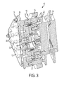
- FIG. 3 illustrates a section of a fast-steering, deformable mirror system, in accordance with one or more embodiments of this disclosure.
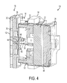
- FIG. 4 illustrates a section of a fast-steering, deformable mirror system, in accordance with one or more embodiments of this disclosure.
- FIG. 5 illustrates an electrical interface, according to one or more embodiments of this disclosure.
- FIG. 6 illustrates an annular junction of an electrical interface, according to one or more embodiments of this disclosure.
- FIG. 7 illustrates a section of a portion of an electrical interface, according to one or more embodiments of this disclosure.
- FIG. 8 illustrates a fast-steering, deformable mirror system, in accordance with one or more embodiments of this disclosure.
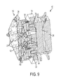
- FIG. 9 illustrates a section of a fast-steering, deformable mirror system, in accordance with one or more embodiments of this disclosure.
- FIG. 10 illustrates a mirror mount assembly, according to one or more embodiments of this disclosure.
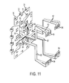
- FIG. 11 illustrates an electrical interface, according to one or more embodiments of this disclosure.
- FIG. 12 illustrates a portion of an electrical interface, according to one or more embodiments of this disclosure.
- FIG. 13 illustrates a section of an electrical interface, according to one or more embodiments of this disclosure.
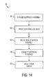
- FIG. 14 illustrates a method of manufacturing a fast-steering, deformable mirror system, in accordance with one or more embodiments of this disclosure.
- FIG. 1 is a diagram illustrating the function of some embodiments of a fast-steering, deformable mirror system 10.
- System 10 is configured to manipulate reflective surface 12 in order to control the reflection of electromagnetic radiation off of reflective surface 12.
- System 10 is configured to steer reflective surface 12 as a unit, and also to deform reflective surface 12.
- System 10 is designed to reduce hysteresis in drive signals that control deformation of reflective surface 12, to maintain an overall size and/or footprint of conventional fast-steering, non-deformable mirror systems, and/or provide other enhancements.
- Deforming reflective surface 12 may mean to change the position and/or orientation of one point on or portion of reflective surface 12 separate from the rest of reflective surface 12.
- System 10 is deployable within a sensor or video system, and/or may form part of a vehicle, vessel, or aircraft carrying such a sensor or video system (e.g., an unmanned vehicle, vessel, or aircraft).
- System 10 may include one or more of base 14, deformable mirror assembly 16, mirror steering assembly 18, mirror mount assembly 20, one or more mirror steering drive circuits 22, deformation drive circuit 24, controller 26, and/or other components.
- Base 14 is configured to provide a substrate on which at least some of the other components of system 10 can be mounted. In use, base 14 is mounted within the larger system that system 10 functions (e.g., within a larger sensor system). Base 14 may be formed from one or more of aluminum alloys, stainless steels, beryllium, or low expansion nickel alloys, and/or other materials. Base 14 may be formed as a single component or as a plurality of separate components coupled together in a fixed configuration. For the purposes of this disclosure, a component may be considered to be connected to base 14 if some point or portion of the component is fixed in position with respect to base 14.
- This may include a component fixed with respect to base 14 by being secure in the environment within which base 14 is installed (e.g., an overall sensor housing or seat), a component affixed at a point or portion to some other component that is immovable (or substantially so) with respect to base, and/or other components that have a point or portion fixed in position with respect to base 14.
- a component fixed with respect to base 14 by being secure in the environment within which base 14 is installed (e.g., an overall sensor housing or seat), a component affixed at a point or portion to some other component that is immovable (or substantially so) with respect to base, and/or other components that have a point or portion fixed in position with respect to base 14.
- Deformable mirror assembly 16 is configured to deform reflective surface 12.
- Deformable mirror assembly 16 includes reflective surface 12, substrate 28, one or more deformation actuators 30, and/or other components.
- Deformable mirror assembly 16 may be formed as a unit that is separate from base 14 and mounted to base 14 (e.g., as discussed further below).
- Deformable mirror assembly 16 may deform reflective surface 12 in order to correct for thermal effects, residual manufacturing imperfections, focus errors, atmospheric distortions near sensor window, and/or other optical effects or artifacts.
- Deformation actuators 30 are carried by substrate 28. Deformation actuators 30 are configured to actively and controllably move different points and/or portions of reflective surface 12 relative to substrate 28 separate from the rest of reflective surface 12. Deformation actuators 30 may include, for example, one or more of piezoelectric elements, electrostrictive, and/or other actuators.
- Mirror steering assembly 18 is configured to actively and controllably actuate deformable mirror assembly 16 as a unit with respect to base 14. Mirror steering assembly 18 is controlled to actuate deformable mirror assembly 16 in order to provide overall mirror steering with respect to reflective surface 12. Mirror steering assembly 18 may be configured as a fast-steering system. Mirror steering assembly 18 may include one or more of steering actuators 32, one or more pickoff members 34, and/or other components.
- Steering actuators 32 are configured to actively position deformable mirror assembly 16 with respect to base 14.
- Steering actuators 32 are mounted to base 14 in a fixed configuration (e.g., fastened, attached, affixed, and/or otherwise secured).
- Steering actuators 32 may include linear drive members that expand and contract linearly. By coordinating the expansion and contraction of steering actuators 32, deformable mirror assembly 16 can be steered with respect to base 14.
- Pickoff members 34 may be configured to define the extremes of relative movement of deformable mirror assembly 16 as a unit with respect to base 14. The definition of these extremes may be a configurable/controllable variable, or may be set at manufacture or calibration.
- Mirror mount assembly 20 is configured to mount deformable mirror assembly 16 to base 14 such that deformable mirror assembly 16 is movable as a unit with respect to base 14.
- Mirror mount assembly 20 may be configured to permit relative motion between deformable mirror assembly 16 and base 14 in at least two degrees of freedom. Some exemplary configurations of mirror mount assembly 20 may be described hereafter (see FIGS. 3 , 4 , 9 , and 10 , and the accompanying description).
- the mirror mount assembly 20 may include a suspension assembly (not shown in FIG. 1 ) configured to resiliently and elastically bias deformable mirror assembly 16 into a default position with respect to base 14.
- Mirror steering drive circuits 22 are configured to drive mirror steering assembly 18. As such, mirror steering drive circuits 22 are electrically coupled with steering actuators 32 and/or pickoff members 34 to provide signals thereto that control the functionality of steering actuators 32 and/or pickoff members 34. For example, the signals provided from mirror steering drive circuits 22 to steering actuators 32 drive steering actuators 32 to actively control the position of deformable mirror assembly 16 with respect to base 14. When system 10 is installed for use, the position of mirror steering drive circuits 22 may be held fixed (or substantially fixed) with respect to base 14.
- Deformation drive circuit 24 is configured to drive deformation actuators 30. As such, deformation drive circuit 24 is electrically coupled with deformation actuators 30 to provide signals thereto that control the functionality of deformation actuators 30. In particular, the signals generated by deformation drive circuit 24 drive deformation actuators 30 to actively deform reflective surface 12. When system 10 is installed for use, the position of mirror steering drive circuits 22 may be held fixed (or substantially fixed) with respect to base 14.
- Controller 26 is configured to provide input to mirror steering drive circuits 22 and deformation drive circuit 24 that is used by mirror steering drive circuits 22 and deformation drive circuit 24 to generate their respective output signals. Controller 26 may use as input parameters such as, for example, 27 inertial angular rate inputs, 29 inertial acceleration inputs, 31 wave front senor input, 33 video sharpness statistics, 35 factory offsets, and/or other parameters.
- system 10 includes an electrical mirror interface (not particularly shown in FIG. 1 ) that is physically connected to deformable mirror assembly 16 and deformation drive circuit 24.
- the electrical mirror interface is formed in part from an elastically resilient polymer material that flexes during relative movement between deformable mirror assembly 16 and base 14.
- the elastically resilient polymer material may include one or more of polyimide, polyether ether ketone, polyester, G10, and/or other materials.
- the electrical mirror interface may be formed as a flexible circuit that transmits signals from deformation drive circuit 24 to deformable mirror assembly 16.
- system 10 includes a suspension assembly that biases deformable mirror assembly 16 into a default position with respect to base 14.
- the electrical mirror interface which is formed from an elastically resilient material, may form at least a portion of the suspension assembly.
- the electrical mirror interface is the only component providing a substantial bias to deformable mirror assembly 16 biasing deformable mirror assembly 16 toward the default position.
- the electrical mirror interface is the only component providing any bias to deformable mirror assembly 16 biasing deformable mirror assembly 16 toward the default position.
- the electrical mirror interface and/or the suspension assembly may take a variety of different shapes.
- the exemplary configurations of the suspension assembly and the electrical mirror interface provided below are exemplary and not limiting.
- the scope of this disclosure includes other configurations in which the electrical mirror interface is formed in part from an elastically resilient polymer material, and/or in which the electrical mirror interface forms at least part of the suspension assembly.
- FIG. 2 illustrates some embodiments of system 10 in which a diaphragm suspension is implemented.
- FIGS. 3 and 4 illustrate cross-sections of system 10 taken along section lines 3-3 and 4-4, respectively.
- the section shown in FIG. 3 illustrates the internals of steering actuators 32 and pickoff members 34, while FIG. 4 provides a more direct view of a diaphragm suspension assembly 36 installed on system 10.
- a set of balancing weights 37 is carried by mirror steering assembly 18, and sit in corresponding openings in base 14.
- mirror mount assembly 20 includes normal support 38. Normal support 38 is fixed at one end with respect to base 14, and the other end holds mirror seat 40. Mirror seat 40 includes central protrusion 42 that extends into a corresponding recess 44 formed in deformable mirror assembly 16. This configuration of mirror mount assembly 20 does not appreciably effect the rotational natural frequencies of deformable mirror assembly 16 parallel to reflective surface 12.
- diaphragm suspension assembly 36 comprises a set of elastic arms 46 and annular junction 48.
- Arms 46 extend from deformation drive circuit 24 (which is disposed on a side of base 14 opposite from deformable mirror assembly 16), travel around base 14, and arrive at annular junction 48 perpendicular to each other. Opening 50 formed in annular junction 48 corresponds to central protrusion 42 such that central protrusion 42 extends therethrough.
- diaphragm suspension assembly 36 includes a set of clamps 52. Clamps 52 fix arms 46 in tension with respect to base 14. Therefore, as deformable mirror assembly 16 is driven to move with respect to base 14, arms 46 flex elastically and bias deformable mirror assembly 16 back toward the default position shown in FIGS. 2-4 .
- FIG. 5 illustrates arms 46 and annular junction 48 of diaphragm suspension assembly 36, in addition to deformation actuators 30.
- arms 46 and annular junction 48 are formed as flexible circuit elements such that electrical leads are carried the length of arms 46 and into annular junction 48.
- Annular junction 48 includes contacts 54 formed thereon, which mate to contact formed on substrate 28 (not shown in FIG. 5 ).
- Arms 46 include contacts 56 configured to interface with deformation drive circuit 24 (not shown in FIG. 5 ).
- signals are conveyed from deformation drive circuit 24 to deformable mirror assembly 16.
- Arms 46, annular junction 48, and contacts 54 form an electrical interface configured to electrically couple deformable mirror assembly 16 (not shown in FIG. 5 ) with deformation drive circuit 24 (not shown in FIG. 5 ).
- FIG. 6 illustrates a portion of diaphragm suspension assembly 36.
- FIG. 6 illustrates annular junction 48 and portions of arms 46.
- FIG. 6 shows electrical leads 58 carried within arms 46 to contacts 54.
- FIG. 7 illustrates a section of annular junction 48, including two contacts 54.
- the electrical leads 58 can be seen in FIG. 7 disposed between layers 60 of resiliently elastic polymer.
- An additional layer 62 of conductive material may be included between layers 60 to enhance strength.
- FIG. 8 illustrates some embodiments of system 10 in which a set of flex blade members 64 are implemented to provide the suspension assembly.
- FIG. 9 illustrates a cross-section of system 10 taken along section line 9-9. The section shown in FIG. 9 illustrates the internals of steering actuators 32 and pickoff members 34, and provides a partial view of how mirror mount assembly 20 holds deformable mirror assembly 16 in place with respect to base 14 along with the suspension assembly formed in part from flex blade members 64.
- FIG. 10 illustrates mirror mount assembly 20 and the suspension assembly in detail.
- mirror mount assembly 20 may include one or more of base interface 66, first gimbal member 68, second gimbal member 70, and/or other components.
- Base interface 66 is mounted directly to base 14 (not shown in FIG. 10 ) in a fixed configuration with base 14.
- Base interface 66 is formed having an elongated (e.g., generally rectangular) cross section (from the direction of base 14). Opposite the side at which base interface 66 is connected to base 14, base interface 66 is tapered, and includes a cutaway 72 in which first gimbal member 68 is disposed, unattached from base interface 66.
- Base interface 66 may be formed from aluminum alloys, stainless steels, beryllium, or low expansion nickel alloys, and/or other materials.
- first gimbal member 68 (from the direction of base 14) is elongated (e.g., generally rectangular). First gimbal member 68 is disposed in cutaway 72 such that the length-wise direction of first gimbal member 68 is perpendicular to the length-wise direction of base interface 66. On a side opposite base 14, first gimbal member 68 is tapered along its lengthwise edges.
- First gimbal member 68 and second gimbal member 70 are secured together and/or formed integrally. First gimbal member 68 and second gimbal member 70 are connected by intermediate portion 74. First gimbal member 68, second gimbal member 70, and/or intermediate portion 74 may be formed from aluminum alloys, stainless steels, beryllium, or low expansion nickel alloys, and/or other materials.
- Second gimbal member 70 has a cross section (from the direction of base 14) that is elongated (e.g., generally rectangular). Second gimbal member 70 is connected to first gimbal member 68 such that the length-wise direction of second gimbal member 70 is perpendicular to the length-wise direction of first gimbal member 68. On a side of second gimbal member 70 opposite base 14, second gimbal member 70 is secured to substrate 28. The interface between second gimbal member 70 and substrate 28 may be fixed or substantially fixed. On the side of second gimbal member 70 facing base 14 (e.g., opposite the interface with substrate 28), second gimbal member 70 is tapered along its length-wise edges.
- Flex blade members 64 are used to attach length-wise edges of second gimbal member 70 with opposing length-wise edges of base interface 66. Additional flex blade members 64 are used to attach length-wise edges of first gimbal member 68 to substrate 28. Due to the elasticity of flex blade members 64, these attachments permit pivoting of deformable mirror assembly 16 with respect to base 14 about a first axis of rotation 76 and a second axis of rotation 78. The elasticity of flex blade members 64 may further permit linear movement of deformable mirror assembly 16 with respect to base 14. The resilient elasticity of flex blade members 64 biases deformable mirror assembly 16 and base 14 into the default position shown in FIGS. 8-10 . The flex blade members 64 are secured to base interface 66, first gimbal member 68, and second gimbal member 70 by clamps which are not shown in FIG. 10 , but which are illustrated in FIG. 9 as elements 80.
- FIG. 11 shows the flexible elements of the suspension assembly, including demand field 64 without any of the other components of system 10 other than deformation actuators 30.
- the suspension assembly includes demand field 64 overlapped over each other such that flex blade members 64 carried by different components of mirror mount assembly 20 (e.g., base interface 66, first gimbal member 68, and/or second gimbal member 70 shown in FIG. 10 ) provide signals across the interfaces between the components.
- flex blade members 64 provide signal paths across the movable interface between base 14 (not shown in FIG. 11 ) and deformable mirror assembly 16 (not shown in FIG. 11 ).
- a set of lines 82 connect flex blade members 64 attached to base interface 66 (not shown in FIG. 11 ) with deformation drive circuit 24 (not shown in FIG. 11 ).
- Lines 82 may be formed from the same materials as flex blade members 64, or lines 82 may be formed from different materials from flex blade members 64.
- a set of electrical contacts 84 is formed at ends of lines 82 opposite flex blade members 64. Electrical contacts 84 are configured for electrical coupling with deformation drive circuit 24 (not shown in FIG. 11 ). Flex blade members 64, lines 82, and electrical contacts 84 form an electrical interface configured to electrically couple deformable mirror assembly 16 with deformation drive circuit 24.
- FIG. 12 illustrates the configuration of one of flex blade members 64.
- Flex blade member 64 is formed as a relatively flat, flexible member.
- Flex blade members 64 includes openings 86, which are configured to facilitate secure attachment of flex blade member 64 to other components.
- a set of electrical lines 88 are formed in flex blade member 64 that provide electrical couplings with electrical contacts 90.
- FIG. 13 illustrates a section of flex blade member 64.
- electrical lines 88 can be seen formed between layers 92 of elastic polymer that provide flex blade member 64 with its flexibility.
- Extra layer 94 of conductor may be disposed between layers 92 to provide flex blade member 64 with enhanced strength.
- FIG. 14 illustrates method 96 of manufacturing or assembling a fast-steering, deformable mirror system.
- the operations of method 96 presented below are intended to be illustrative. In some embodiments, method 96 may be accomplished with one or more additional operations not described, and/or without one or more of the operations discussed. Additionally, the order in which the operations of method 96 are illustrated in FIG. 14 and described below is not intended to be limiting.
- a suspension assembly is provided.
- the suspension system is configured to flexibly bias a deformable mirror assembly into a default position with respect to a base.
- the suspension system may be similar to or the same as the suspension systems illustrated, for example, in FIGS. 2-13 and described above.
- a mirror steering assembly may be provided.
- the mirror steering assembly is configured to actuate the deformable mirror assembly as a unit with respect to the base.
- the mirror steering assembly may be similar to or the same as mirror steering assembly 18 (shown in FIGS. 1-4 , 8 , and 9 , and described above).
- the base may be mounted to the deformable mirror assembly.
- the deformable mirror assembly Upon mounting, the deformable mirror assembly is movable as a unit with respect to the base with at least to degrees of freedom.
- operation 102 may include mounting the deformable mirror assembly to the base using a mirror mount assembly similar to or the same as mirror mount assembly 20 (shown in FIGS. 1 , 3 , 4 , 9 , and 10 , and described above).
- an electrical mirror interface is connected to the base and the mirror assembly.
- the electrical mirror interface is configured to electrically couple the deformable mirror assembly with a drive circuit to convey drive signals from the drive circuit to the deformable mirror assembly.
- the electrical mirror interface may be formed in part from an elastically resilient polymer material.
- the electrical mirror interface may form at least a portion of the suspension system. In some implementations, the electrical mirror interface may be similar to or the same as the electrical interfaces illustrated in FIGS. 5 and 11 .
Landscapes
- Physics & Mathematics (AREA)
- General Physics & Mathematics (AREA)
- Optics & Photonics (AREA)
- Mechanical Light Control Or Optical Switches (AREA)
- Mechanical Optical Scanning Systems (AREA)
Applications Claiming Priority (1)
| Application Number | Priority Date | Filing Date | Title |
|---|---|---|---|
| US12/887,364 US8322870B2 (en) | 2010-09-21 | 2010-09-21 | Fast steering, deformable mirror system and method for manufacturing the same |
Publications (2)
| Publication Number | Publication Date |
|---|---|
| EP2431784A1 true EP2431784A1 (de) | 2012-03-21 |
| EP2431784B1 EP2431784B1 (de) | 2017-04-05 |
Family
ID=44533868
Family Applications (1)
| Application Number | Title | Priority Date | Filing Date |
|---|---|---|---|
| EP11174455.3A Active EP2431784B1 (de) | 2010-09-21 | 2011-07-19 | Schnell lenkendes, deformierbares Spiegelsystem und Herstellungsverfahren dafür |
Country Status (3)
| Country | Link |
|---|---|
| US (1) | US8322870B2 (de) |
| EP (1) | EP2431784B1 (de) |
| IL (1) | IL214150A0 (de) |
Families Citing this family (7)
| Publication number | Priority date | Publication date | Assignee | Title |
|---|---|---|---|---|
| US9612436B1 (en) | 2014-08-12 | 2017-04-04 | Ball Aerospace & Technologies Corp. | High-speed scanner-tracker |
| JP6536164B2 (ja) * | 2015-05-18 | 2019-07-03 | 日本精機株式会社 | ヘッドアップディスプレイ装置 |
| US10031329B2 (en) * | 2015-08-13 | 2018-07-24 | The Boeing Company | Off-axis optical telescope |
| CN107942472B (zh) * | 2017-12-07 | 2023-05-23 | 西安工业大学 | 稀疏孔径成像系统光束相位补偿反射镜 |
| US20200192058A1 (en) * | 2018-12-12 | 2020-06-18 | Toshiba Tec Kabushiki Kaisha | Mirror device |
| CN113791493B (zh) * | 2021-06-03 | 2022-09-20 | 北京航空航天大学 | 一种基于宏微两级复合作动的快速反射镜 |
| DE102022204643A1 (de) | 2022-05-12 | 2023-11-16 | Carl Zeiss Smt Gmbh | Optisches system, lithographieanlage mit einem optischen system und verfahren zum herstellen eines optischen systems |
Citations (3)
| Publication number | Priority date | Publication date | Assignee | Title |
|---|---|---|---|---|
| US4194189A (en) * | 1977-04-05 | 1980-03-18 | Agence Nationale De Valorisation De La Recherche (Anvar) | Control devices of the relay type |
| US7380950B1 (en) * | 2005-02-15 | 2008-06-03 | Lockheed Martin Corporation | Hybrid high-bandwidth deformable fast steering mirror |
| KR20090063012A (ko) * | 2007-12-13 | 2009-06-17 | 현대자동차주식회사 | 광 스위치 모듈 |
Family Cites Families (8)
| Publication number | Priority date | Publication date | Assignee | Title |
|---|---|---|---|---|
| US4655563A (en) * | 1985-11-25 | 1987-04-07 | Itek Corporation | Variable thickness deformable mirror |
| US5229889A (en) * | 1991-12-10 | 1993-07-20 | Hughes Aircraft Company | Simple adaptive optical system |
| US5526208A (en) * | 1994-08-17 | 1996-06-11 | Quantum Corporation | Flex circuit vibration sensor |
| US5766022A (en) * | 1996-05-21 | 1998-06-16 | International Business Machines Corporation | Electrical assembly |
| US6024340A (en) * | 1996-12-04 | 2000-02-15 | Active Control Experts, Inc. | Valve assembly |
| US20060050419A1 (en) * | 2004-09-08 | 2006-03-09 | Ealey Mark A | Integrated wavefront correction module |
| JP2007103657A (ja) * | 2005-10-04 | 2007-04-19 | Canon Inc | 光学素子保持装置、露光装置およびデバイス製造方法 |
| WO2009007447A2 (en) * | 2007-07-11 | 2009-01-15 | Universite Libre De Bruxelles | Deformable mirror |
-
2010
- 2010-09-21 US US12/887,364 patent/US8322870B2/en active Active
-
2011
- 2011-07-18 IL IL214150A patent/IL214150A0/en active IP Right Grant
- 2011-07-19 EP EP11174455.3A patent/EP2431784B1/de active Active
Patent Citations (3)
| Publication number | Priority date | Publication date | Assignee | Title |
|---|---|---|---|---|
| US4194189A (en) * | 1977-04-05 | 1980-03-18 | Agence Nationale De Valorisation De La Recherche (Anvar) | Control devices of the relay type |
| US7380950B1 (en) * | 2005-02-15 | 2008-06-03 | Lockheed Martin Corporation | Hybrid high-bandwidth deformable fast steering mirror |
| KR20090063012A (ko) * | 2007-12-13 | 2009-06-17 | 현대자동차주식회사 | 광 스위치 모듈 |
Also Published As
| Publication number | Publication date |
|---|---|
| IL214150A0 (en) | 2011-11-30 |
| EP2431784B1 (de) | 2017-04-05 |
| US8322870B2 (en) | 2012-12-04 |
| US20120069463A1 (en) | 2012-03-22 |
Similar Documents
| Publication | Publication Date | Title |
|---|---|---|
| EP2431784B1 (de) | Schnell lenkendes, deformierbares Spiegelsystem und Herstellungsverfahren dafür | |
| JP2937977B2 (ja) | 半導体処理技法によって作製された移動追跡アンテナ | |
| US10516348B2 (en) | MEMS actuator package architecture | |
| US4871244A (en) | Movable member mounting | |
| JP4372344B2 (ja) | 宇宙望遠鏡の鏡などの装置のための、位置補正機能をもつ一体および小型の均衡取付けアセンブリ | |
| US20170131162A1 (en) | Piezoresistive Position Sensor Systems | |
| US20080007851A1 (en) | Thin, nearly wireless adaptive optical device | |
| US20180024350A1 (en) | Imaging device | |
| JP2016519915A (ja) | 反作用補償チルトプラットフォーム | |
| JP2002321195A (ja) | 振動体およびその製造方法 | |
| EP3752880B1 (de) | Kolokationssignalverarbeitungsvorrichtung mit mikromechanisch abtastendem siliziumspiegel | |
| US8727548B1 (en) | Field steering mirror | |
| US6327065B1 (en) | Fine pointing assembly configuration | |
| US20010013251A1 (en) | Vibrating gyroscope and electronic apparatus incorporating the same | |
| JP7137964B2 (ja) | 振れ補正機能付き光学ユニット及びその製造方法 | |
| US6209395B1 (en) | Accelerometer | |
| JP4595779B2 (ja) | 角速度センサ | |
| CN116941170A (zh) | 致动器-传感器系统和具有这种致动器-传感器系统的快速转向镜(fsm) | |
| JP7415444B2 (ja) | 振動デバイス、電子機器および移動体 | |
| CA1232470A (en) | Linear acceleration compensation for multisensor | |
| KR20230109371A (ko) | 센서 시프팅 액추에이터 및 이를 포함하는 카메라 모듈 | |
| US20210285833A1 (en) | Force sensor assembly | |
| Coppoolse et al. | Dual-axis single-mirror mechanism for beam steering and stabilisation in optical inter satellite links | |
| JP2018132312A (ja) | 薄膜歪センサとそれを用いたトルクセンサ | |
| US9500854B2 (en) | Beam steering mirror device |
Legal Events
| Date | Code | Title | Description |
|---|---|---|---|
| PUAI | Public reference made under article 153(3) epc to a published international application that has entered the european phase |
Free format text: ORIGINAL CODE: 0009012 |
|
| AK | Designated contracting states |
Kind code of ref document: A1 Designated state(s): AL AT BE BG CH CY CZ DE DK EE ES FI FR GB GR HR HU IE IS IT LI LT LU LV MC MK MT NL NO PL PT RO RS SE SI SK SM TR |
|
| AX | Request for extension of the european patent |
Extension state: BA ME |
|
| RIN1 | Information on inventor provided before grant (corrected) |
Inventor name: MILLER, KIRK A. |
|
| 17P | Request for examination filed |
Effective date: 20120920 |
|
| REG | Reference to a national code |
Ref country code: DE Ref legal event code: R079 Ref document number: 602011036597 Country of ref document: DE Free format text: PREVIOUS MAIN CLASS: G02B0026080000 Ipc: G02B0007182000 |
|
| GRAP | Despatch of communication of intention to grant a patent |
Free format text: ORIGINAL CODE: EPIDOSNIGR1 |
|
| RIC1 | Information provided on ipc code assigned before grant |
Ipc: G02B 7/182 20060101AFI20160929BHEP Ipc: G02B 26/08 20060101ALI20160929BHEP |
|
| INTG | Intention to grant announced |
Effective date: 20161026 |
|
| GRAS | Grant fee paid |
Free format text: ORIGINAL CODE: EPIDOSNIGR3 |
|
| GRAA | (expected) grant |
Free format text: ORIGINAL CODE: 0009210 |
|
| AK | Designated contracting states |
Kind code of ref document: B1 Designated state(s): AL AT BE BG CH CY CZ DE DK EE ES FI FR GB GR HR HU IE IS IT LI LT LU LV MC MK MT NL NO PL PT RO RS SE SI SK SM TR |
|
| REG | Reference to a national code |
Ref country code: GB Ref legal event code: FG4D |
|
| REG | Reference to a national code |
Ref country code: CH Ref legal event code: EP |
|
| REG | Reference to a national code |
Ref country code: AT Ref legal event code: REF Ref document number: 882330 Country of ref document: AT Kind code of ref document: T Effective date: 20170415 |
|
| REG | Reference to a national code |
Ref country code: IE Ref legal event code: FG4D |
|
| REG | Reference to a national code |
Ref country code: DE Ref legal event code: R096 Ref document number: 602011036597 Country of ref document: DE |
|
| REG | Reference to a national code |
Ref country code: FR Ref legal event code: PLFP Year of fee payment: 7 |
|
| REG | Reference to a national code |
Ref country code: NL Ref legal event code: MP Effective date: 20170405 |
|
| REG | Reference to a national code |
Ref country code: LT Ref legal event code: MG4D |
|
| REG | Reference to a national code |
Ref country code: AT Ref legal event code: MK05 Ref document number: 882330 Country of ref document: AT Kind code of ref document: T Effective date: 20170405 |
|
| PG25 | Lapsed in a contracting state [announced via postgrant information from national office to epo] |
Ref country code: NL Free format text: LAPSE BECAUSE OF FAILURE TO SUBMIT A TRANSLATION OF THE DESCRIPTION OR TO PAY THE FEE WITHIN THE PRESCRIBED TIME-LIMIT Effective date: 20170405 |
|
| PG25 | Lapsed in a contracting state [announced via postgrant information from national office to epo] |
Ref country code: AT Free format text: LAPSE BECAUSE OF FAILURE TO SUBMIT A TRANSLATION OF THE DESCRIPTION OR TO PAY THE FEE WITHIN THE PRESCRIBED TIME-LIMIT Effective date: 20170405 Ref country code: NO Free format text: LAPSE BECAUSE OF FAILURE TO SUBMIT A TRANSLATION OF THE DESCRIPTION OR TO PAY THE FEE WITHIN THE PRESCRIBED TIME-LIMIT Effective date: 20170705 Ref country code: HR Free format text: LAPSE BECAUSE OF FAILURE TO SUBMIT A TRANSLATION OF THE DESCRIPTION OR TO PAY THE FEE WITHIN THE PRESCRIBED TIME-LIMIT Effective date: 20170405 Ref country code: ES Free format text: LAPSE BECAUSE OF FAILURE TO SUBMIT A TRANSLATION OF THE DESCRIPTION OR TO PAY THE FEE WITHIN THE PRESCRIBED TIME-LIMIT Effective date: 20170405 Ref country code: FI Free format text: LAPSE BECAUSE OF FAILURE TO SUBMIT A TRANSLATION OF THE DESCRIPTION OR TO PAY THE FEE WITHIN THE PRESCRIBED TIME-LIMIT Effective date: 20170405 Ref country code: LT Free format text: LAPSE BECAUSE OF FAILURE TO SUBMIT A TRANSLATION OF THE DESCRIPTION OR TO PAY THE FEE WITHIN THE PRESCRIBED TIME-LIMIT Effective date: 20170405 Ref country code: GR Free format text: LAPSE BECAUSE OF FAILURE TO SUBMIT A TRANSLATION OF THE DESCRIPTION OR TO PAY THE FEE WITHIN THE PRESCRIBED TIME-LIMIT Effective date: 20170706 |
|
| PG25 | Lapsed in a contracting state [announced via postgrant information from national office to epo] |
Ref country code: SE Free format text: LAPSE BECAUSE OF FAILURE TO SUBMIT A TRANSLATION OF THE DESCRIPTION OR TO PAY THE FEE WITHIN THE PRESCRIBED TIME-LIMIT Effective date: 20170405 Ref country code: LV Free format text: LAPSE BECAUSE OF FAILURE TO SUBMIT A TRANSLATION OF THE DESCRIPTION OR TO PAY THE FEE WITHIN THE PRESCRIBED TIME-LIMIT Effective date: 20170405 Ref country code: BG Free format text: LAPSE BECAUSE OF FAILURE TO SUBMIT A TRANSLATION OF THE DESCRIPTION OR TO PAY THE FEE WITHIN THE PRESCRIBED TIME-LIMIT Effective date: 20170705 Ref country code: PL Free format text: LAPSE BECAUSE OF FAILURE TO SUBMIT A TRANSLATION OF THE DESCRIPTION OR TO PAY THE FEE WITHIN THE PRESCRIBED TIME-LIMIT Effective date: 20170405 Ref country code: RS Free format text: LAPSE BECAUSE OF FAILURE TO SUBMIT A TRANSLATION OF THE DESCRIPTION OR TO PAY THE FEE WITHIN THE PRESCRIBED TIME-LIMIT Effective date: 20170405 Ref country code: IS Free format text: LAPSE BECAUSE OF FAILURE TO SUBMIT A TRANSLATION OF THE DESCRIPTION OR TO PAY THE FEE WITHIN THE PRESCRIBED TIME-LIMIT Effective date: 20170805 |
|
| REG | Reference to a national code |
Ref country code: DE Ref legal event code: R097 Ref document number: 602011036597 Country of ref document: DE |
|
| PG25 | Lapsed in a contracting state [announced via postgrant information from national office to epo] |
Ref country code: RO Free format text: LAPSE BECAUSE OF FAILURE TO SUBMIT A TRANSLATION OF THE DESCRIPTION OR TO PAY THE FEE WITHIN THE PRESCRIBED TIME-LIMIT Effective date: 20170405 Ref country code: CZ Free format text: LAPSE BECAUSE OF FAILURE TO SUBMIT A TRANSLATION OF THE DESCRIPTION OR TO PAY THE FEE WITHIN THE PRESCRIBED TIME-LIMIT Effective date: 20170405 Ref country code: DK Free format text: LAPSE BECAUSE OF FAILURE TO SUBMIT A TRANSLATION OF THE DESCRIPTION OR TO PAY THE FEE WITHIN THE PRESCRIBED TIME-LIMIT Effective date: 20170405 Ref country code: SK Free format text: LAPSE BECAUSE OF FAILURE TO SUBMIT A TRANSLATION OF THE DESCRIPTION OR TO PAY THE FEE WITHIN THE PRESCRIBED TIME-LIMIT Effective date: 20170405 Ref country code: EE Free format text: LAPSE BECAUSE OF FAILURE TO SUBMIT A TRANSLATION OF THE DESCRIPTION OR TO PAY THE FEE WITHIN THE PRESCRIBED TIME-LIMIT Effective date: 20170405 |
|
| PLBE | No opposition filed within time limit |
Free format text: ORIGINAL CODE: 0009261 |
|
| STAA | Information on the status of an ep patent application or granted ep patent |
Free format text: STATUS: NO OPPOSITION FILED WITHIN TIME LIMIT |
|
| PG25 | Lapsed in a contracting state [announced via postgrant information from national office to epo] |
Ref country code: IT Free format text: LAPSE BECAUSE OF FAILURE TO SUBMIT A TRANSLATION OF THE DESCRIPTION OR TO PAY THE FEE WITHIN THE PRESCRIBED TIME-LIMIT Effective date: 20170405 Ref country code: SM Free format text: LAPSE BECAUSE OF FAILURE TO SUBMIT A TRANSLATION OF THE DESCRIPTION OR TO PAY THE FEE WITHIN THE PRESCRIBED TIME-LIMIT Effective date: 20170405 |
|
| REG | Reference to a national code |
Ref country code: CH Ref legal event code: PL |
|
| 26N | No opposition filed |
Effective date: 20180108 |
|
| REG | Reference to a national code |
Ref country code: IE Ref legal event code: MM4A |
|
| PG25 | Lapsed in a contracting state [announced via postgrant information from national office to epo] |
Ref country code: LI Free format text: LAPSE BECAUSE OF NON-PAYMENT OF DUE FEES Effective date: 20170731 Ref country code: IE Free format text: LAPSE BECAUSE OF NON-PAYMENT OF DUE FEES Effective date: 20170719 Ref country code: CH Free format text: LAPSE BECAUSE OF NON-PAYMENT OF DUE FEES Effective date: 20170731 |
|
| PG25 | Lapsed in a contracting state [announced via postgrant information from national office to epo] |
Ref country code: SI Free format text: LAPSE BECAUSE OF FAILURE TO SUBMIT A TRANSLATION OF THE DESCRIPTION OR TO PAY THE FEE WITHIN THE PRESCRIBED TIME-LIMIT Effective date: 20170405 |
|
| REG | Reference to a national code |
Ref country code: BE Ref legal event code: MM Effective date: 20170731 |
|
| REG | Reference to a national code |
Ref country code: FR Ref legal event code: PLFP Year of fee payment: 8 |
|
| PG25 | Lapsed in a contracting state [announced via postgrant information from national office to epo] |
Ref country code: LU Free format text: LAPSE BECAUSE OF NON-PAYMENT OF DUE FEES Effective date: 20170719 |
|
| PG25 | Lapsed in a contracting state [announced via postgrant information from national office to epo] |
Ref country code: BE Free format text: LAPSE BECAUSE OF NON-PAYMENT OF DUE FEES Effective date: 20170731 |
|
| PG25 | Lapsed in a contracting state [announced via postgrant information from national office to epo] |
Ref country code: MT Free format text: LAPSE BECAUSE OF NON-PAYMENT OF DUE FEES Effective date: 20170719 |
|
| PG25 | Lapsed in a contracting state [announced via postgrant information from national office to epo] |
Ref country code: HU Free format text: LAPSE BECAUSE OF FAILURE TO SUBMIT A TRANSLATION OF THE DESCRIPTION OR TO PAY THE FEE WITHIN THE PRESCRIBED TIME-LIMIT; INVALID AB INITIO Effective date: 20110719 Ref country code: MC Free format text: LAPSE BECAUSE OF FAILURE TO SUBMIT A TRANSLATION OF THE DESCRIPTION OR TO PAY THE FEE WITHIN THE PRESCRIBED TIME-LIMIT Effective date: 20170405 |
|
| PG25 | Lapsed in a contracting state [announced via postgrant information from national office to epo] |
Ref country code: CY Free format text: LAPSE BECAUSE OF NON-PAYMENT OF DUE FEES Effective date: 20170405 |
|
| PG25 | Lapsed in a contracting state [announced via postgrant information from national office to epo] |
Ref country code: MK Free format text: LAPSE BECAUSE OF FAILURE TO SUBMIT A TRANSLATION OF THE DESCRIPTION OR TO PAY THE FEE WITHIN THE PRESCRIBED TIME-LIMIT Effective date: 20170405 |
|
| PG25 | Lapsed in a contracting state [announced via postgrant information from national office to epo] |
Ref country code: TR Free format text: LAPSE BECAUSE OF FAILURE TO SUBMIT A TRANSLATION OF THE DESCRIPTION OR TO PAY THE FEE WITHIN THE PRESCRIBED TIME-LIMIT Effective date: 20170405 |
|
| PG25 | Lapsed in a contracting state [announced via postgrant information from national office to epo] |
Ref country code: PT Free format text: LAPSE BECAUSE OF FAILURE TO SUBMIT A TRANSLATION OF THE DESCRIPTION OR TO PAY THE FEE WITHIN THE PRESCRIBED TIME-LIMIT Effective date: 20170405 |
|
| PG25 | Lapsed in a contracting state [announced via postgrant information from national office to epo] |
Ref country code: AL Free format text: LAPSE BECAUSE OF FAILURE TO SUBMIT A TRANSLATION OF THE DESCRIPTION OR TO PAY THE FEE WITHIN THE PRESCRIBED TIME-LIMIT Effective date: 20170405 |
|
| P01 | Opt-out of the competence of the unified patent court (upc) registered |
Effective date: 20230530 |
|
| PGFP | Annual fee paid to national office [announced via postgrant information from national office to epo] |
Ref country code: GB Payment date: 20250619 Year of fee payment: 15 |
|
| PGFP | Annual fee paid to national office [announced via postgrant information from national office to epo] |
Ref country code: FR Payment date: 20250620 Year of fee payment: 15 |
|
| PGFP | Annual fee paid to national office [announced via postgrant information from national office to epo] |
Ref country code: DE Payment date: 20250620 Year of fee payment: 15 |