EP2431609B1 - Windturbine mit horizontaler Achse - Google Patents
Windturbine mit horizontaler Achse Download PDFInfo
- Publication number
- EP2431609B1 EP2431609B1 EP11181208.7A EP11181208A EP2431609B1 EP 2431609 B1 EP2431609 B1 EP 2431609B1 EP 11181208 A EP11181208 A EP 11181208A EP 2431609 B1 EP2431609 B1 EP 2431609B1
- Authority
- EP
- European Patent Office
- Prior art keywords
- tower
- section
- flange
- frame
- wind turbine
- Prior art date
- Legal status (The legal status is an assumption and is not a legal conclusion. Google has not performed a legal analysis and makes no representation as to the accuracy of the status listed.)
- Not-in-force
Links
- 239000011796 hollow space material Substances 0.000 claims description 8
- 230000005611 electricity Effects 0.000 claims description 2
- 238000010276 construction Methods 0.000 description 7
- 238000011161 development Methods 0.000 description 3
- 230000006835 compression Effects 0.000 description 2
- 238000007906 compression Methods 0.000 description 2
- 230000000694 effects Effects 0.000 description 2
- 238000003780 insertion Methods 0.000 description 2
- 230000037431 insertion Effects 0.000 description 2
- 108010072255 Integrin alpha3beta1 Proteins 0.000 description 1
- 238000005452 bending Methods 0.000 description 1
- 239000012141 concentrate Substances 0.000 description 1
- 238000013461 design Methods 0.000 description 1
- 238000010586 diagram Methods 0.000 description 1
- 238000009434 installation Methods 0.000 description 1
- 238000012423 maintenance Methods 0.000 description 1
- 238000004519 manufacturing process Methods 0.000 description 1
- 238000000034 method Methods 0.000 description 1
- 230000008439 repair process Effects 0.000 description 1
- 230000003313 weakening effect Effects 0.000 description 1
Images

Classifications
-
- F—MECHANICAL ENGINEERING; LIGHTING; HEATING; WEAPONS; BLASTING
- F03—MACHINES OR ENGINES FOR LIQUIDS; WIND, SPRING, OR WEIGHT MOTORS; PRODUCING MECHANICAL POWER OR A REACTIVE PROPULSIVE THRUST, NOT OTHERWISE PROVIDED FOR
- F03D—WIND MOTORS
- F03D13/00—Assembly, mounting or commissioning of wind motors; Arrangements specially adapted for transporting wind motor components
- F03D13/20—Arrangements for mounting or supporting wind motors; Masts or towers for wind motors
-
- F—MECHANICAL ENGINEERING; LIGHTING; HEATING; WEAPONS; BLASTING
- F03—MACHINES OR ENGINES FOR LIQUIDS; WIND, SPRING, OR WEIGHT MOTORS; PRODUCING MECHANICAL POWER OR A REACTIVE PROPULSIVE THRUST, NOT OTHERWISE PROVIDED FOR
- F03D—WIND MOTORS
- F03D9/00—Adaptations of wind motors for special use; Combinations of wind motors with apparatus driven thereby; Wind motors specially adapted for installation in particular locations
- F03D9/20—Wind motors characterised by the driven apparatus
- F03D9/25—Wind motors characterised by the driven apparatus the apparatus being an electrical generator
-
- F—MECHANICAL ENGINEERING; LIGHTING; HEATING; WEAPONS; BLASTING
- F05—INDEXING SCHEMES RELATING TO ENGINES OR PUMPS IN VARIOUS SUBCLASSES OF CLASSES F01-F04
- F05B—INDEXING SCHEME RELATING TO WIND, SPRING, WEIGHT, INERTIA OR LIKE MOTORS, TO MACHINES OR ENGINES FOR LIQUIDS COVERED BY SUBCLASSES F03B, F03D AND F03G
- F05B2260/00—Function
- F05B2260/30—Retaining components in desired mutual position
- F05B2260/301—Retaining bolts or nuts
-
- Y—GENERAL TAGGING OF NEW TECHNOLOGICAL DEVELOPMENTS; GENERAL TAGGING OF CROSS-SECTIONAL TECHNOLOGIES SPANNING OVER SEVERAL SECTIONS OF THE IPC; TECHNICAL SUBJECTS COVERED BY FORMER USPC CROSS-REFERENCE ART COLLECTIONS [XRACs] AND DIGESTS
- Y02—TECHNOLOGIES OR APPLICATIONS FOR MITIGATION OR ADAPTATION AGAINST CLIMATE CHANGE
- Y02E—REDUCTION OF GREENHOUSE GAS [GHG] EMISSIONS, RELATED TO ENERGY GENERATION, TRANSMISSION OR DISTRIBUTION
- Y02E10/00—Energy generation through renewable energy sources
- Y02E10/70—Wind energy
- Y02E10/72—Wind turbines with rotation axis in wind direction
-
- Y—GENERAL TAGGING OF NEW TECHNOLOGICAL DEVELOPMENTS; GENERAL TAGGING OF CROSS-SECTIONAL TECHNOLOGIES SPANNING OVER SEVERAL SECTIONS OF THE IPC; TECHNICAL SUBJECTS COVERED BY FORMER USPC CROSS-REFERENCE ART COLLECTIONS [XRACs] AND DIGESTS
- Y02—TECHNOLOGIES OR APPLICATIONS FOR MITIGATION OR ADAPTATION AGAINST CLIMATE CHANGE
- Y02E—REDUCTION OF GREENHOUSE GAS [GHG] EMISSIONS, RELATED TO ENERGY GENERATION, TRANSMISSION OR DISTRIBUTION
- Y02E10/00—Energy generation through renewable energy sources
- Y02E10/70—Wind energy
- Y02E10/728—Onshore wind turbines
Definitions
- the present invention relates to a structure for mounting parts inside a wind turbine tower.
- component parts such as a power module have been mounted inside the tower of a wind turbine that is constructed as a wind power generator.
- parts such as a power module are mounted in the space inside the tower being arranged in a vertical layered shape. That is, in the literature above, a part such as a power module is mounted to the base of the tower before the tower is raised, and a frame is provided in order to mount other parts above this part.
- This frame comprises a parts mounting section in which parts are mounted, and columns that support the parts mounting section, with the bottom ends of the columns being fastened to the base of the tower.
- the parts mounting section of the frame is placed above the part that is mounted on the base. Therefore, it is possible to mount other parts above the part.
- the conventional art described above has the following problems.
- the bottom end of the frame is fastened to the base of the tower, so there is a problem in that the work of positioning and the work of fastening the frame on site (for example, the work of fastening the frame to the base using anchor bolts) requires time, and there is a problem in that the precision of positioning the frame depends on on-site work.
- the tower sways due to the wind or movement of the wind turbine.
- a bending moment is applied to the tower, thus a compression load and a tensile load are alternately applied to the side wall sections of the tower.
- the compression load is directly transmitted from the side wall sections to the base, and the tensile load may concentrate in the connection section between the bottom end of the tower and the base.
- a wind turbine wherein the tower of the turbine comprises one or more tubular tower sections having an outer jacket wall and an inward directed flange in its lower and upper ends, and at least one platform arranged inside the tower for facilitating access for maintenance and repairs to the inner of the tower and to the nacelle. It is an object to provide a tower for a wind turbine, in which platforms and other equipment may be arranged inside the tower in a cost effective and highly flexible way without weakening the tower structure.
- a horizontal axis wind turbine comprising:
- a frame on which parts are mounted is supported by the tip end section of the second flange of the base section to which the bottom end section of the tower is fastened.
- a horizontal-axis wind turbine comprises a rotor having blades and a hub that holds the blades, a nacelle that axially supports the rotor by way of a main shaft that is connected to the hub, and a tower that supports the nacelle such that the nacelle is capable of free yaw rotation.
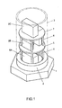
- the tower is erected on a base using the construction illustrated in FIG. 1 .
- the base fitting 2 is embedded in and fastened to the base 1.
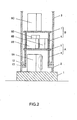
- the base fitting 2 is cylindrical in shape, and as illustrated in FIG. 2 and FIG. 3 , an inner flange 13 is provided on the top end.
- the tower 3 is cylindrical in shape, and as illustrated in FIG. 1 and FIG. 2 , is placed on the base fitting 2.
- An inner flange 12 is provided on the bottom end of the tower 3.
- side wall section 30 of the tower 3 is placed on the side wall 20 of the base fitting 2, and the underneath side of the inner flange 12 is placed together with the upper side of the inner flange 13 of the base fitting 2.
- Bolt insertion holes are formed in the inner flange 12 and inner flange 13, and as illustrated in FIG. 3 , bolts 9 are inserted through the bolt insertion holes, and the inner flange 13 of the base fitting 2 and the inner flange 12 of the tower 3 are fastened together by the bolts 9 and nuts 11. As appropriate, washers 10 are used.
- the tower is erected with this kind of construction.
- a frame A and frame B are located inside the tower 3.
- Frame A is a lower frame and is supported by the base fitting 2.
- Frame B is an upper frame and is located above frame A.
- Frame A has a part mounting unit 5, and a plurality of leg sections 4, 4, that upwardly support that part mounting unit 5.
- the frame B has a part mounting unit 7 and a plurality of leg sections 6, 6, ... that upwardly support that part mounting unit 7.
- the leg sections 4 and leg sections 6 are column shaped members, however they are not limited to this form.
- an inside end section 13b that protrudes further inward than the inside end of the inner flange 12 of the tower 3 is provided on the inside end of the inner flange 13 of the base fitting 2.
- a portion 13a of the inner flange 13 is the connecting portion that connects to the inner flange 12.
- the inside end section 13b is formed such that it protrudes even further inward from the connecting portion 13a.
- leg sections 4, 4, ... of frame A are placed on the inside end section 13b, and by doing so, frame A is supported by the base fitting 2.
- the inside end section 13b is used as the footing for frame A.
- the leg sections 4, 4, ... stand on the inside end section 13b and frame A is supported by the base fitting 2.
- the inside end section 13b can be formed around the entire circumference, or can be formed in parts that include the locations necessary for the footings of frame A.
- the inside end section 13b is located below the surface a1 where the inner flanges 12, 13 fit together by way of a stepped section a2 from that surface a1.
- the stepped section a2 is located further inside than the inner flange 12, and this makes it possible to maintain a gap a3 between the leg sections 4 and the inner flange 12.
- the leg section 4 is separated from the nut 11 by the amount of the gap a3, so makes the work of connection using the bolt 9 and nut 11 easier. Also contact between the inner flange 12 and the leg section 4 when the tower is swaying is prevented.
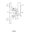
- FIG. 4 is also effective of other construction for maintaining a gap a3 between the leg section 4 and inner flange 12.
- the construction illustrated in FIG. 4 has extending section 4a that extends outward from the bottom end of the leg section 4.
- the extending section 4a is placed on the inside end section 13b.
- a stepped section b2 is located at the same position as the inside end of the inner flange 12, however, by forming the extending section 4a, it is possible to maintain a gap b3 between the leg section 4 and inner flange 12.
- parts 8A, 8B and 8C are mounted on this structure.
- Parts 8A, 8B and 8C are devices such as the power module that are necessary for constructing this wind turbine as a power generator.
- Part 8A is placed on the base 1 on the inside of the base fitting 2. There is a space between the part mounting unit 5 of frame A and the base 1, and part 8A is placed in this space.
- Part 8B is mounted on the part mounting unit 5 of frame A. There is space between the part mounting unit 7 of frame B and the part mounting unit 5 of frame A, and part 8B is placed in this space.
- Part 8C is mounted on the part mounting unit 7 of frame B.
- this structure is constructed with frames A and B, and has two layers of part mounting units.
- the base 1 When the base 1 is included, there are three layers of part mounting spaces. Furthermore, it is possible to place a frame above frame B and increase the part mounting layers. Regardless of this embodiment, the invention can be embodied without employing frame B above the frame.
- part 8A is installed on the base 1.
- frame A is installed on top of the base fitting 2.
- Part 8B is then installed on the part mounting 5 unit of frame A.
- frame B is installed on top frame A.
- Part 8C is installed on the part mounting unit 7 of frame B.
- the invention has a structure as described above, so a compressing load that is transmitted from the side wall section 30 of the tower 3 as the tower 3 sways is directly transmitted from the side wall section 30 of the tower 3 to the side wall section 20 of the base fitting 2 as indicated by arrows c1 and c2 in FIG. 3 , and thus excessive stress does not occur at the connection section between the tower 3 and the base fitting 2.
- a tensile load that is transmitted from the side wall section 30 of the tower 3 as the tower 3 sways is transmitted to the side wall section 20 of the base fitting 2 by way of the connection section between the tower 3 and base fitting 2, or in other words by way of the inner flange 12, nut 11, bolt 9 and inner flange 13.
- the weight d2 of the frames A and B and the weight of the parts 8A, 8B and 8C placed on the frames A and B applies an initial stress to the connection section between the tower 3 and base fitting 2 that acts in a direction opposite of the tensile load d1.
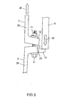
- the leg section 4 of the frame A was supported by the inside end section of the inner flange 13 of the base fitting 2.
Landscapes
- Engineering & Computer Science (AREA)
- Life Sciences & Earth Sciences (AREA)
- Sustainable Development (AREA)
- Sustainable Energy (AREA)
- Chemical & Material Sciences (AREA)
- Combustion & Propulsion (AREA)
- Mechanical Engineering (AREA)
- General Engineering & Computer Science (AREA)
- Power Engineering (AREA)
- Wind Motors (AREA)
Claims (4)
- Windturbine mit horizontaler Achse, die Folgendes umfasst:- eine Hauptwindturbineneinheit zur Erzeugung von Elektrizität;- einen Turm (3) mit einem oberen Endabschnitt und einem unteren Endabschnitt, wobei der obere Endabschnitt des Turms (3) die Hauptwindturbineneinheit trägt und der untere Endabschnitt des Turms (3) an einer Basis (1) befestigt ist und wobei die Seite des unteren Endabschnitts des Turms (3) einen darin ausgebildeten Hohlraum aufweist; und- einen Rahmen (A), der in dem Hohlraum des Turms (3) angeordnet ist, wobei eine vorgegebene Ausrüstung (8A, 8B, 8C), die für Elektrizitätserzeugung verwendet wird, die durch die Haupteinheit der Windturbine ausgeführt wird, an dem Rahmen (A) angebracht ist,- wobei der Turm (3) mit einem ersten Flansch (12) versehen ist, der konfiguriert ist, sich von dem unteren Ende des Turms (3) in horizontaler Richtung in Richtung des Inneren des Hohlraums zu erstrecken,- wobei die Basis (1) mit einem zweiten Flansch (13) versehen ist, der konfiguriert ist, sich längs des ersten Flansches (12) und im Wesentlichen mit dem ersten Flansch (12) in die gleiche Richtung zu erstrecken, wobei der zweite Flansch (13) in der vertikalen Richtung an dem ersten Flansch (12) befestigt ist, und- wobei der erste Flansch (12) und der zweite Flansch (13) ein proximales und ein distales Ende aufweisen und wobei der Rahmen (A) von dem distalen Ende des zweiten Flansches (13) gestützt wird.
- Windturbine mit horizontaler Achse nach Anspruch 1,
wobei eine Aussparung (a3) an der oberen Fläche des zweiten Flansches (13) auf Seiten des distalen Endes vorgesehen ist, wobei die Aussparung weiter im Inneren des Hohlraums als das distale Ende des ersten Flansches (12) angeordnet ist; und
wobei der Rahmen (A) durch die Aussparung des zweiten Flansches (13) gestützt wird. - Windturbine mit horizontaler Achse nach Anspruch 1 oder 2,
wobei der Rahmen (A) einen Beinabschnitt (4), der durch das distale Ende des zweiten Flansches (13) gestützt wird, und einen Anbringungsabschnitt (5), der durch den Beinabschnitt (4) gestützt wird, und an dem die vorgegebene Ausrüstung angebracht ist, aufweist,
wobei der Beinabschnitt (4) mit einem verlängerten Abschnitt (4a) versehen ist, der sich von dem unteren Ende des Beinabschnitts (4) in Richtung der Außenseite des Turms (3) erstreckt, und
wobei durch den verlängerten Abschnitt (4a) zwischen dem Beinabschnitt (4) und dem proximalen Ende des ersten Flansches (12) ein Zwischenraum (b2, b3) gebildet wird. - Windturbine mit horizontaler Achse nach einem der Ansprüche 1 bis 3, die ferner einen weiteren Rahmen (B) umfasst, der auf dem Rahmen (A) steht.
Applications Claiming Priority (1)
| Application Number | Priority Date | Filing Date | Title |
|---|---|---|---|
| JP2010210319A JP5667822B2 (ja) | 2010-09-21 | 2010-09-21 | 風車タワー内の部品搭載構造 |
Publications (3)
| Publication Number | Publication Date |
|---|---|
| EP2431609A2 EP2431609A2 (de) | 2012-03-21 |
| EP2431609A3 EP2431609A3 (de) | 2014-05-28 |
| EP2431609B1 true EP2431609B1 (de) | 2015-07-08 |
Family
ID=44582721
Family Applications (1)
| Application Number | Title | Priority Date | Filing Date |
|---|---|---|---|
| EP11181208.7A Not-in-force EP2431609B1 (de) | 2010-09-21 | 2011-09-14 | Windturbine mit horizontaler Achse |
Country Status (3)
| Country | Link |
|---|---|
| US (1) | US20120066998A1 (de) |
| EP (1) | EP2431609B1 (de) |
| JP (1) | JP5667822B2 (de) |
Families Citing this family (10)
| Publication number | Priority date | Publication date | Assignee | Title |
|---|---|---|---|---|
| PT2653715T (pt) * | 2012-04-19 | 2016-07-19 | Nordex Energy Gmbh | Torre para um aerogerador e metódo para edificação da mesma |
| CN104334874B (zh) | 2012-06-08 | 2017-11-21 | 维斯塔斯风力系统集团公司 | 开关器件在风力涡轮机塔架中的布置 |
| US8839586B2 (en) * | 2012-09-14 | 2014-09-23 | General Electric Company | Tower section and method for installing tower for wind turbine |
| EP2746577A1 (de) * | 2012-12-21 | 2014-06-25 | Areva Wind GmbH | Windkraftanlage, Abschnitt einer Stützstruktur einer Windkraftanlage und Verfahren zur Montage eines Abschnitts |
| EP2767654B1 (de) * | 2013-02-19 | 2015-07-29 | Siemens Aktiengesellschaft | Flanschhilfsmittel zum Verbinden von benachbarten Turmabschnitten |
| CN203685498U (zh) * | 2013-09-29 | 2014-07-02 | 西门子公司 | 用于设置在风机塔筒内设备的机械构架及其风力发电机 |
| WO2018133964A1 (en) * | 2017-01-18 | 2018-07-26 | Siemens Wind Power A/S | Standardized platform arrangement of a wind turbine |
| BE1025030B1 (nl) * | 2017-08-04 | 2018-10-03 | GeoSea N.V. | Zelfdragende steunconstructie voor windturbine-apparatuur |
| ES2963836T3 (es) * | 2018-03-28 | 2024-04-02 | General Electric Renovables Espana Sl | Conjunto de estructura interna independiente para una torre de turbina eólica |
| GB2601507B (en) * | 2020-12-01 | 2023-08-16 | Subsea 7 Ltd | Installing equipment in offshore monopile foundations |
Family Cites Families (33)
| Publication number | Priority date | Publication date | Assignee | Title |
|---|---|---|---|---|
| US3793794A (en) * | 1972-09-15 | 1974-02-26 | Arlo Inc | Stacked column |
| US4225264A (en) * | 1978-09-18 | 1980-09-30 | Lynos, Inc. | Method and apparatus for coupling engagement of misalignable flanges |
| JPS61247876A (ja) * | 1985-04-26 | 1986-11-05 | Yamaguchi Kikai Kenkyusho:Kk | 全方位貫流型風車発電装置 |
| US5623526A (en) * | 1995-07-21 | 1997-04-22 | Combustion Engineering, Inc. | Method and apparatus for repair of nuclear reactor shroud |
| US5802129A (en) * | 1996-01-11 | 1998-09-01 | General Electric Company | Mechanically joined replacement shroud for boiling water nuclear reactor |
| GB2311502B (en) * | 1996-03-08 | 2000-06-14 | Marconi Gec Ltd | Mounting of machinery within a vessel |
| JP2001159260A (ja) * | 1999-12-01 | 2001-06-12 | Kokuyo Denko Kk | 支柱の接続構造 |
| WO2002036301A2 (en) * | 2000-11-03 | 2002-05-10 | Applied Materials, Inc. | Installation docking pedestal for_wafer fabrication equipment |
| WO2002065119A1 (en) | 2001-02-09 | 2002-08-22 | The Trustees Of Columbia University In The City Of New York | A method for the prediction of molecular interaction networks |
| DE20114647U1 (de) * | 2001-07-17 | 2002-01-03 | Schlemenat, Alfred, 45701 Herten | Windenergieanlage |
| DE10145414B4 (de) * | 2001-09-14 | 2013-09-12 | Aloys Wobben | Verfahren zur Errichtung einer Windenergieanlage, Windenergieanlage |
| DK200200178A (da) * | 2002-02-06 | 2003-08-07 | Vestas Wind Sys As | Ophængningsmidler til vindturbinetårne |
| NL1019953C2 (nl) * | 2002-02-12 | 2002-12-19 | Mecal Applied Mechanics B V | Geprefabriceerde toren of mast, alsmede een methode voor het samenvoegen en/of naspannen van segmenten die één constructie moeten vormen, alsmede een werkwijze voor het opbouwen van een toren of mast bestaande uit segmenten. |
| BRPI0406933B1 (pt) * | 2003-02-01 | 2014-04-08 | Aloys Wobben | Instalação de energia eólica, e, processo para a montagem da mesma |
| US7665273B2 (en) * | 2003-04-09 | 2010-02-23 | General Electric Company | Method for generating a substantially uninterrupted connection of the peripheral wall portions of two adjacent tubular segments |
| JP2006009596A (ja) * | 2004-06-22 | 2006-01-12 | Tohoku Electric Power Engineering & Construction Co Ltd | 変電開閉設備を内蔵した風力発電装置およびその施工方法 |
| CA2591536A1 (en) * | 2004-11-23 | 2006-06-01 | Vestas Wind Systems A/S | A wind turbine, a method for assembling and handling the wind turbine and uses hereof |
| US7762037B2 (en) * | 2005-11-18 | 2010-07-27 | General Electric Company | Segment for a tower of a wind energy turbine and method for arranging operating components of a wind energy turbine in a tower thereof |
| US8051627B2 (en) * | 2006-04-30 | 2011-11-08 | General Electric Company | Tower adapter, method of producing a tower foundation and tower foundation |
| US20080041009A1 (en) * | 2006-08-18 | 2008-02-21 | General Electric | Flangeless support structures |
| WO2008092350A1 (en) * | 2007-01-26 | 2008-08-07 | Baotou Wind Power Science & Technology Co., Ltd. Of China Water Investment Group | A flange assembly, a coupling flange and an assembly method thereof |
| US20080236061A1 (en) * | 2007-03-26 | 2008-10-02 | Dry Basement, Inc. | Floor slab support system |
| DE102007031065B4 (de) * | 2007-06-28 | 2011-05-05 | Nordex Energy Gmbh | Windenergieanlagenturm |
| US8047804B2 (en) * | 2007-12-27 | 2011-11-01 | General Electric Company | Wind tower and method of assembling the same |
| US8646219B2 (en) | 2008-05-30 | 2014-02-11 | General Electric Company | Fixture for locating wind turbine equipment on foundation prior to tower installation |
| CN101737273A (zh) * | 2008-11-17 | 2010-06-16 | 维斯塔斯风力系统集团公司 | 塔架、风力发电机组以及在塔架内设置平台的方法 |
| ES2386519T3 (es) * | 2008-11-27 | 2012-08-22 | Vestas Wind Systems A/S | Torre para una turbina eólica y método para montar la torre |
| DE102009016893B4 (de) * | 2009-04-08 | 2011-12-08 | Nordex Energy Gmbh | Verankerungsbauteil für einen Windenergieanlagenturm |
| US8490337B2 (en) * | 2009-06-09 | 2013-07-23 | Thomas Nott Word, III | Structural flange connection system and method |
| US20100132269A1 (en) * | 2009-06-15 | 2010-06-03 | General Electric Company | Rail-transportable wind turbine tower |
| US8201378B2 (en) * | 2009-07-29 | 2012-06-19 | General Electric Company | Guide system for power modules |
| US8087898B2 (en) * | 2009-12-15 | 2012-01-03 | General Electric Company | Stress relief flange and method for distributing stress for wind turbine components |
| US8468776B2 (en) * | 2010-06-16 | 2013-06-25 | Cortina Innovations S.A. de C.V. | Flange for wind power generators |
-
2010
- 2010-09-21 JP JP2010210319A patent/JP5667822B2/ja not_active Expired - Fee Related
-
2011
- 2011-09-14 EP EP11181208.7A patent/EP2431609B1/de not_active Not-in-force
- 2011-09-21 US US13/238,106 patent/US20120066998A1/en not_active Abandoned
Also Published As
| Publication number | Publication date |
|---|---|
| JP2012067603A (ja) | 2012-04-05 |
| US20120066998A1 (en) | 2012-03-22 |
| EP2431609A3 (de) | 2014-05-28 |
| JP5667822B2 (ja) | 2015-02-12 |
| EP2431609A2 (de) | 2012-03-21 |
Similar Documents
| Publication | Publication Date | Title |
|---|---|---|
| EP2431609B1 (de) | Windturbine mit horizontaler Achse | |
| EP3538760B1 (de) | Elektrische einheit für eine windturbine | |
| DK2570555T3 (en) | A tower base section of a wind turbine, a wind turbine and a system for mounting a tower | |
| EP2444663B1 (de) | Festlandwindturbine mit turmstützsystem | |
| CN1971037B (zh) | 风力涡轮的塔段以及在塔中布置风力涡轮的操作部件的方法 | |
| US8322107B2 (en) | Wind turbine tower and wind turbine generator | |
| US8302365B2 (en) | Partially self-erecting wind turbine tower | |
| EP3130796B1 (de) | Windturbinenanordnungssystem und zugehöriges verfahren | |
| US20100325986A1 (en) | System for joining a gondola to the concrete tower of an aerogenerator | |
| KR20090091043A (ko) | 풍력 발전 설비의 타워 섹션 수송 방법 및 풍력 발전 설비의 타워 섹션 | |
| EP2375058A2 (de) | Montage von Komponenten innerhalb einer großen Windkraftanlage | |
| JP2009209938A (ja) | 風力エネルギータービンのタワー内の構成要素を組み立てる方法及びシステム | |
| US20130174509A1 (en) | Platform assembly for a wind turbine tower | |
| KR20110068332A (ko) | 풍력발전기의 타워 모듈 | |
| EP2136074B1 (de) | Trägerrahmen für die Gondel einer Windturbine | |
| WO2022103348A1 (en) | A multi-pod support structure for a wind turbine tower | |
| CN108026899A (zh) | 用于风力发电机的塔 | |
| US11905923B2 (en) | Wind turbine tower segment for a wind turbine tower and method | |
| WO2022254475A1 (ja) | コンクリート支柱と鋼管支柱とからなる風力発電設備の支柱 | |
| EP2808546B1 (de) | Zwischenabschnitt, Offshore-Windgenerator und Offshore-Windpark | |
| US20230265836A1 (en) | Wind turbine and method for manufacturing a wind turbine | |
| US12467433B2 (en) | Wind power generation system | |
| CN212987676U (zh) | 一种单柱式太阳能支架加固装置 | |
| CN112523967A (zh) | 一种格构式综合轴风机塔架 | |
| WO2023274478A1 (en) | Stabilized wind turbines, systems for stabilizing wind turbines, and methods for installing same |
Legal Events
| Date | Code | Title | Description |
|---|---|---|---|
| PUAI | Public reference made under article 153(3) epc to a published international application that has entered the european phase |
Free format text: ORIGINAL CODE: 0009012 |
|
| AK | Designated contracting states |
Kind code of ref document: A2 Designated state(s): AL AT BE BG CH CY CZ DE DK EE ES FI FR GB GR HR HU IE IS IT LI LT LU LV MC MK MT NL NO PL PT RO RS SE SI SK SM TR |
|
| AX | Request for extension of the european patent |
Extension state: BA ME |
|
| RAP1 | Party data changed (applicant data changed or rights of an application transferred) |
Owner name: HITACHI, LTD. |
|
| PUAL | Search report despatched |
Free format text: ORIGINAL CODE: 0009013 |
|
| AK | Designated contracting states |
Kind code of ref document: A3 Designated state(s): AL AT BE BG CH CY CZ DE DK EE ES FI FR GB GR HR HU IE IS IT LI LT LU LV MC MK MT NL NO PL PT RO RS SE SI SK SM TR |
|
| AX | Request for extension of the european patent |
Extension state: BA ME |
|
| RIC1 | Information provided on ipc code assigned before grant |
Ipc: F03D 11/04 20060101AFI20140424BHEP |
|
| 17P | Request for examination filed |
Effective date: 20140718 |
|
| RBV | Designated contracting states (corrected) |
Designated state(s): AL AT BE BG CH CY CZ DE DK EE ES FI FR GB GR HR HU IE IS IT LI LT LU LV MC MK MT NL NO PL PT RO RS SE SI SK SM TR |
|
| GRAP | Despatch of communication of intention to grant a patent |
Free format text: ORIGINAL CODE: EPIDOSNIGR1 |
|
| INTG | Intention to grant announced |
Effective date: 20150116 |
|
| GRAS | Grant fee paid |
Free format text: ORIGINAL CODE: EPIDOSNIGR3 |
|
| GRAA | (expected) grant |
Free format text: ORIGINAL CODE: 0009210 |
|
| AK | Designated contracting states |
Kind code of ref document: B1 Designated state(s): AL AT BE BG CH CY CZ DE DK EE ES FI FR GB GR HR HU IE IS IT LI LT LU LV MC MK MT NL NO PL PT RO RS SE SI SK SM TR |
|
| REG | Reference to a national code |
Ref country code: GB Ref legal event code: FG4D |
|
| REG | Reference to a national code |
Ref country code: AT Ref legal event code: REF Ref document number: 735627 Country of ref document: AT Kind code of ref document: T Effective date: 20150715 Ref country code: CH Ref legal event code: EP |
|
| REG | Reference to a national code |
Ref country code: IE Ref legal event code: FG4D |
|
| REG | Reference to a national code |
Ref country code: DE Ref legal event code: R096 Ref document number: 602011017632 Country of ref document: DE |
|
| REG | Reference to a national code |
Ref country code: AT Ref legal event code: MK05 Ref document number: 735627 Country of ref document: AT Kind code of ref document: T Effective date: 20150708 |
|
| REG | Reference to a national code |
Ref country code: NL Ref legal event code: MP Effective date: 20150708 |
|
| REG | Reference to a national code |
Ref country code: LT Ref legal event code: MG4D |
|
| PG25 | Lapsed in a contracting state [announced via postgrant information from national office to epo] |
Ref country code: LV Free format text: LAPSE BECAUSE OF FAILURE TO SUBMIT A TRANSLATION OF THE DESCRIPTION OR TO PAY THE FEE WITHIN THE PRESCRIBED TIME-LIMIT Effective date: 20150708 Ref country code: LT Free format text: LAPSE BECAUSE OF FAILURE TO SUBMIT A TRANSLATION OF THE DESCRIPTION OR TO PAY THE FEE WITHIN THE PRESCRIBED TIME-LIMIT Effective date: 20150708 Ref country code: NO Free format text: LAPSE BECAUSE OF FAILURE TO SUBMIT A TRANSLATION OF THE DESCRIPTION OR TO PAY THE FEE WITHIN THE PRESCRIBED TIME-LIMIT Effective date: 20151008 Ref country code: FI Free format text: LAPSE BECAUSE OF FAILURE TO SUBMIT A TRANSLATION OF THE DESCRIPTION OR TO PAY THE FEE WITHIN THE PRESCRIBED TIME-LIMIT Effective date: 20150708 Ref country code: GR Free format text: LAPSE BECAUSE OF FAILURE TO SUBMIT A TRANSLATION OF THE DESCRIPTION OR TO PAY THE FEE WITHIN THE PRESCRIBED TIME-LIMIT Effective date: 20151009 |
|
| PG25 | Lapsed in a contracting state [announced via postgrant information from national office to epo] |
Ref country code: AT Free format text: LAPSE BECAUSE OF FAILURE TO SUBMIT A TRANSLATION OF THE DESCRIPTION OR TO PAY THE FEE WITHIN THE PRESCRIBED TIME-LIMIT Effective date: 20150708 Ref country code: PT Free format text: LAPSE BECAUSE OF FAILURE TO SUBMIT A TRANSLATION OF THE DESCRIPTION OR TO PAY THE FEE WITHIN THE PRESCRIBED TIME-LIMIT Effective date: 20151109 Ref country code: HR Free format text: LAPSE BECAUSE OF FAILURE TO SUBMIT A TRANSLATION OF THE DESCRIPTION OR TO PAY THE FEE WITHIN THE PRESCRIBED TIME-LIMIT Effective date: 20150708 Ref country code: IS Free format text: LAPSE BECAUSE OF FAILURE TO SUBMIT A TRANSLATION OF THE DESCRIPTION OR TO PAY THE FEE WITHIN THE PRESCRIBED TIME-LIMIT Effective date: 20151108 Ref country code: PL Free format text: LAPSE BECAUSE OF FAILURE TO SUBMIT A TRANSLATION OF THE DESCRIPTION OR TO PAY THE FEE WITHIN THE PRESCRIBED TIME-LIMIT Effective date: 20150708 Ref country code: ES Free format text: LAPSE BECAUSE OF FAILURE TO SUBMIT A TRANSLATION OF THE DESCRIPTION OR TO PAY THE FEE WITHIN THE PRESCRIBED TIME-LIMIT Effective date: 20150708 Ref country code: RS Free format text: LAPSE BECAUSE OF FAILURE TO SUBMIT A TRANSLATION OF THE DESCRIPTION OR TO PAY THE FEE WITHIN THE PRESCRIBED TIME-LIMIT Effective date: 20150708 Ref country code: SE Free format text: LAPSE BECAUSE OF FAILURE TO SUBMIT A TRANSLATION OF THE DESCRIPTION OR TO PAY THE FEE WITHIN THE PRESCRIBED TIME-LIMIT Effective date: 20150708 |
|
| REG | Reference to a national code |
Ref country code: DE Ref legal event code: R097 Ref document number: 602011017632 Country of ref document: DE |
|
| PG25 | Lapsed in a contracting state [announced via postgrant information from national office to epo] |
Ref country code: EE Free format text: LAPSE BECAUSE OF FAILURE TO SUBMIT A TRANSLATION OF THE DESCRIPTION OR TO PAY THE FEE WITHIN THE PRESCRIBED TIME-LIMIT Effective date: 20150708 Ref country code: IT Free format text: LAPSE BECAUSE OF FAILURE TO SUBMIT A TRANSLATION OF THE DESCRIPTION OR TO PAY THE FEE WITHIN THE PRESCRIBED TIME-LIMIT Effective date: 20150708 Ref country code: LU Free format text: LAPSE BECAUSE OF FAILURE TO SUBMIT A TRANSLATION OF THE DESCRIPTION OR TO PAY THE FEE WITHIN THE PRESCRIBED TIME-LIMIT Effective date: 20150914 Ref country code: MC Free format text: LAPSE BECAUSE OF FAILURE TO SUBMIT A TRANSLATION OF THE DESCRIPTION OR TO PAY THE FEE WITHIN THE PRESCRIBED TIME-LIMIT Effective date: 20150708 Ref country code: SK Free format text: LAPSE BECAUSE OF FAILURE TO SUBMIT A TRANSLATION OF THE DESCRIPTION OR TO PAY THE FEE WITHIN THE PRESCRIBED TIME-LIMIT Effective date: 20150708 Ref country code: DK Free format text: LAPSE BECAUSE OF FAILURE TO SUBMIT A TRANSLATION OF THE DESCRIPTION OR TO PAY THE FEE WITHIN THE PRESCRIBED TIME-LIMIT Effective date: 20150708 Ref country code: CZ Free format text: LAPSE BECAUSE OF FAILURE TO SUBMIT A TRANSLATION OF THE DESCRIPTION OR TO PAY THE FEE WITHIN THE PRESCRIBED TIME-LIMIT Effective date: 20150708 |
|
| REG | Reference to a national code |
Ref country code: CH Ref legal event code: PL |
|
| PLBE | No opposition filed within time limit |
Free format text: ORIGINAL CODE: 0009261 |
|
| STAA | Information on the status of an ep patent application or granted ep patent |
Free format text: STATUS: NO OPPOSITION FILED WITHIN TIME LIMIT |
|
| PG25 | Lapsed in a contracting state [announced via postgrant information from national office to epo] |
Ref country code: RO Free format text: LAPSE BECAUSE OF FAILURE TO SUBMIT A TRANSLATION OF THE DESCRIPTION OR TO PAY THE FEE WITHIN THE PRESCRIBED TIME-LIMIT Effective date: 20150708 |
|
| 26N | No opposition filed |
Effective date: 20160411 |
|
| REG | Reference to a national code |
Ref country code: IE Ref legal event code: MM4A |
|
| REG | Reference to a national code |
Ref country code: FR Ref legal event code: ST Effective date: 20160531 |
|
| PG25 | Lapsed in a contracting state [announced via postgrant information from national office to epo] |
Ref country code: LI Free format text: LAPSE BECAUSE OF NON-PAYMENT OF DUE FEES Effective date: 20150930 Ref country code: IE Free format text: LAPSE BECAUSE OF NON-PAYMENT OF DUE FEES Effective date: 20150914 Ref country code: CH Free format text: LAPSE BECAUSE OF NON-PAYMENT OF DUE FEES Effective date: 20150930 |
|
| PG25 | Lapsed in a contracting state [announced via postgrant information from national office to epo] |
Ref country code: SI Free format text: LAPSE BECAUSE OF FAILURE TO SUBMIT A TRANSLATION OF THE DESCRIPTION OR TO PAY THE FEE WITHIN THE PRESCRIBED TIME-LIMIT Effective date: 20150708 Ref country code: FR Free format text: LAPSE BECAUSE OF NON-PAYMENT OF DUE FEES Effective date: 20150930 |
|
| PG25 | Lapsed in a contracting state [announced via postgrant information from national office to epo] |
Ref country code: BE Free format text: LAPSE BECAUSE OF FAILURE TO SUBMIT A TRANSLATION OF THE DESCRIPTION OR TO PAY THE FEE WITHIN THE PRESCRIBED TIME-LIMIT Effective date: 20150708 |
|
| PG25 | Lapsed in a contracting state [announced via postgrant information from national office to epo] |
Ref country code: MT Free format text: LAPSE BECAUSE OF FAILURE TO SUBMIT A TRANSLATION OF THE DESCRIPTION OR TO PAY THE FEE WITHIN THE PRESCRIBED TIME-LIMIT Effective date: 20150708 |
|
| PG25 | Lapsed in a contracting state [announced via postgrant information from national office to epo] |
Ref country code: BG Free format text: LAPSE BECAUSE OF FAILURE TO SUBMIT A TRANSLATION OF THE DESCRIPTION OR TO PAY THE FEE WITHIN THE PRESCRIBED TIME-LIMIT Effective date: 20150708 Ref country code: SM Free format text: LAPSE BECAUSE OF FAILURE TO SUBMIT A TRANSLATION OF THE DESCRIPTION OR TO PAY THE FEE WITHIN THE PRESCRIBED TIME-LIMIT Effective date: 20150708 Ref country code: HU Free format text: LAPSE BECAUSE OF FAILURE TO SUBMIT A TRANSLATION OF THE DESCRIPTION OR TO PAY THE FEE WITHIN THE PRESCRIBED TIME-LIMIT; INVALID AB INITIO Effective date: 20110914 |
|
| PG25 | Lapsed in a contracting state [announced via postgrant information from national office to epo] |
Ref country code: NL Free format text: LAPSE BECAUSE OF FAILURE TO SUBMIT A TRANSLATION OF THE DESCRIPTION OR TO PAY THE FEE WITHIN THE PRESCRIBED TIME-LIMIT Effective date: 20150708 Ref country code: CY Free format text: LAPSE BECAUSE OF FAILURE TO SUBMIT A TRANSLATION OF THE DESCRIPTION OR TO PAY THE FEE WITHIN THE PRESCRIBED TIME-LIMIT Effective date: 20150708 |
|
| PG25 | Lapsed in a contracting state [announced via postgrant information from national office to epo] |
Ref country code: TR Free format text: LAPSE BECAUSE OF FAILURE TO SUBMIT A TRANSLATION OF THE DESCRIPTION OR TO PAY THE FEE WITHIN THE PRESCRIBED TIME-LIMIT Effective date: 20150708 |
|
| PG25 | Lapsed in a contracting state [announced via postgrant information from national office to epo] |
Ref country code: MK Free format text: LAPSE BECAUSE OF FAILURE TO SUBMIT A TRANSLATION OF THE DESCRIPTION OR TO PAY THE FEE WITHIN THE PRESCRIBED TIME-LIMIT Effective date: 20150708 |
|
| PG25 | Lapsed in a contracting state [announced via postgrant information from national office to epo] |
Ref country code: AL Free format text: LAPSE BECAUSE OF FAILURE TO SUBMIT A TRANSLATION OF THE DESCRIPTION OR TO PAY THE FEE WITHIN THE PRESCRIBED TIME-LIMIT Effective date: 20150708 |
|
| PGFP | Annual fee paid to national office [announced via postgrant information from national office to epo] |
Ref country code: DE Payment date: 20180904 Year of fee payment: 8 |
|
| PGFP | Annual fee paid to national office [announced via postgrant information from national office to epo] |
Ref country code: GB Payment date: 20180912 Year of fee payment: 8 |
|
| REG | Reference to a national code |
Ref country code: DE Ref legal event code: R119 Ref document number: 602011017632 Country of ref document: DE |
|
| PG25 | Lapsed in a contracting state [announced via postgrant information from national office to epo] |
Ref country code: DE Free format text: LAPSE BECAUSE OF NON-PAYMENT OF DUE FEES Effective date: 20200401 |
|
| GBPC | Gb: european patent ceased through non-payment of renewal fee |
Effective date: 20190914 |
|
| PG25 | Lapsed in a contracting state [announced via postgrant information from national office to epo] |
Ref country code: GB Free format text: LAPSE BECAUSE OF NON-PAYMENT OF DUE FEES Effective date: 20190914 |