EP2431256A2 - Suspension for baby pushchairs - Google Patents
Suspension for baby pushchairs Download PDFInfo
- Publication number
- EP2431256A2 EP2431256A2 EP11380023A EP11380023A EP2431256A2 EP 2431256 A2 EP2431256 A2 EP 2431256A2 EP 11380023 A EP11380023 A EP 11380023A EP 11380023 A EP11380023 A EP 11380023A EP 2431256 A2 EP2431256 A2 EP 2431256A2
- Authority
- EP
- European Patent Office
- Prior art keywords
- suspension
- longitudinal elements
- frame
- support
- wheel
- Prior art date
- Legal status (The legal status is an assumption and is not a legal conclusion. Google has not performed a legal analysis and makes no representation as to the accuracy of the status listed.)
- Withdrawn
Links
- 239000000725 suspension Substances 0.000 title claims abstract description 19
- 239000000463 material Substances 0.000 description 1
Images
Classifications
-
- B—PERFORMING OPERATIONS; TRANSPORTING
- B62—LAND VEHICLES FOR TRAVELLING OTHERWISE THAN ON RAILS
- B62B—HAND-PROPELLED VEHICLES, e.g. HAND CARTS OR PERAMBULATORS; SLEDGES
- B62B9/00—Accessories or details specially adapted for children's carriages or perambulators
- B62B9/18—Resilient suspensions of bodies
-
- B—PERFORMING OPERATIONS; TRANSPORTING
- B60—VEHICLES IN GENERAL
- B60G—VEHICLE SUSPENSION ARRANGEMENTS
- B60G15/00—Resilient suspensions characterised by arrangement, location or type of combined spring and vibration damper, e.g. telescopic type
- B60G15/02—Resilient suspensions characterised by arrangement, location or type of combined spring and vibration damper, e.g. telescopic type having mechanical spring
- B60G15/06—Resilient suspensions characterised by arrangement, location or type of combined spring and vibration damper, e.g. telescopic type having mechanical spring and fluid damper
- B60G15/061—Resilient suspensions characterised by arrangement, location or type of combined spring and vibration damper, e.g. telescopic type having mechanical spring and fluid damper with a coil spring being mounted inside the damper
-
- B—PERFORMING OPERATIONS; TRANSPORTING
- B60—VEHICLES IN GENERAL
- B60G—VEHICLE SUSPENSION ARRANGEMENTS
- B60G3/00—Resilient suspensions for a single wheel
- B60G3/18—Resilient suspensions for a single wheel with two or more pivoted arms, e.g. parallelogram
- B60G3/20—Resilient suspensions for a single wheel with two or more pivoted arms, e.g. parallelogram all arms being rigid
-
- B—PERFORMING OPERATIONS; TRANSPORTING
- B60—VEHICLES IN GENERAL
- B60G—VEHICLE SUSPENSION ARRANGEMENTS
- B60G2200/00—Indexing codes relating to suspension types
- B60G2200/10—Independent suspensions
- B60G2200/14—Independent suspensions with lateral arms
- B60G2200/144—Independent suspensions with lateral arms with two lateral arms forming a parallelogram
-
- B—PERFORMING OPERATIONS; TRANSPORTING
- B60—VEHICLES IN GENERAL
- B60G—VEHICLE SUSPENSION ARRANGEMENTS
- B60G2300/00—Indexing codes relating to the type of vehicle
- B60G2300/22—Perambulators
-
- B—PERFORMING OPERATIONS; TRANSPORTING
- B62—LAND VEHICLES FOR TRAVELLING OTHERWISE THAN ON RAILS
- B62B—HAND-PROPELLED VEHICLES, e.g. HAND CARTS OR PERAMBULATORS; SLEDGES
- B62B2301/00—Wheel arrangements; Steering; Stability; Wheel suspension
- B62B2301/20—Resilient wheel suspension using springs
Definitions
- This invention consists of a suspension system that is a significant improvement over known models, both in simplicity and strength, characterised by the fact that whatever the pressure on the suspension, the wheel remains in correct vertical position at all times.
- this suspension has two longitudinal elements between the frame and the wheel support, substantially parallel and their ends are articulated onto the frame and the support, with a damper located between the articulations of the opposite ends of the longitudinal elements.
- the damper device is a telescopic element with a spring inside it and the longitudinal elements are composed of plates.
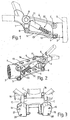
- the suspension forms an assembly comprising, as can be seen in figures 1 and 2 , the fitting, between a lower part (1) of the frame and the wheel (3), support (2), an upper plate (4) and a lower plate (5) substantially parallel to each other and that are articulated to the frame and support by the articulations (6 and 7) and (8 and 9) at their ends respectively, a damper (10) device being located between the articulation (6 and 9) of the opposite ends of the plates (4 and 5), comprising a telescopic element formed by the parts (11 and 12) between which is a coil spring (13).
- the plates (4 and 5) have holes (14) to reduce their weight.
- FIG. 3 shows one of these accessories (C) comprising a body (15), secured by clamps (16) to the lower side (1') of the frame, whose body has two arms (17 and 18) with the holes (19 and 20) for the articulation shafts (6 and 8), respectively.
Landscapes
- Engineering & Computer Science (AREA)
- Mechanical Engineering (AREA)
- Health & Medical Sciences (AREA)
- Public Health (AREA)
- Chemical & Material Sciences (AREA)
- Combustion & Propulsion (AREA)
- Transportation (AREA)
- Carriages For Children, Sleds, And Other Hand-Operated Vehicles (AREA)
- Toys (AREA)
- Vehicle Body Suspensions (AREA)
Abstract
Description
- Suspension for baby pushchairs.
- Several models of suspension for baby pushchairs exist, based principally on the action of a spring, with the spring being placed, for example between the frame and the wheel bracket, or coupled to a support on the wheel axle.
- This invention consists of a suspension system that is a significant improvement over known models, both in simplicity and strength, characterised by the fact that whatever the pressure on the suspension, the wheel remains in correct vertical position at all times.
- The characteristic feature of this suspension is that it has two longitudinal elements between the frame and the wheel support, substantially parallel and their ends are articulated onto the frame and the support, with a damper located between the articulations of the opposite ends of the longitudinal elements.
- The damper device is a telescopic element with a spring inside it and the longitudinal elements are composed of plates.
- These and other characterizing features will be best made apparent by the following detailed description whose understanding will be made easier by the accompanying sheet of drawings showing a practical embodiment being cited only by way of example not limiting the scope of the present invention.
- In the drawings:
-
Figure 1 shows an elevation view of the suspension assembly object of the invention, -
Figure 2 illustrates a perspective view of the suspension assembly, and -
Figure 3 shows a perspective front view of the assembly coupled to a frame for fitting this suspension. - According to the drawings, the suspension forms an assembly comprising, as can be seen in
figures 1 and 2 , the fitting, between a lower part (1) of the frame and the wheel (3), support (2), an upper plate (4) and a lower plate (5) substantially parallel to each other and that are articulated to the frame and support by the articulations (6 and 7) and (8 and 9) at their ends respectively, a damper (10) device being located between the articulation (6 and 9) of the opposite ends of the plates (4 and 5), comprising a telescopic element formed by the parts (11 and 12) between which is a coil spring (13). - The plates (4 and 5) have holes (14) to reduce their weight.
- This suspension may be adapted to different types of existing frames for which purpose an accessory will be fitted to them, to which the suspension will be attached.
Figure 3 shows one of these accessories (C) comprising a body (15), secured by clamps (16) to the lower side (1') of the frame, whose body has two arms (17 and 18) with the holes (19 and 20) for the articulation shafts (6 and 8), respectively. - The invention can within its essentiality be put into practice in other embodiments differing only in detail from the one having been described above only by way of example, said other embodiments also falling within the scope of the protection being claimed. This suspension for baby pushchairs for baby pushchairs may thus be manufactured in any shape and size, with the most suitable means and materials and with the most convenient accessories, and the components may be replaced by others that are technically equivalent, as all of this is contained within the spirit of the claims.
Claims (3)
- Suspension for baby pushchairs, characterised in that it has two longitudinal elements between the frame and the wheel support, substantially parallel to each another and their ends are articulated onto the frame and the support, with a damper located between the articulations of the opposite ends of the longitudinal elements.
- Suspension for baby pushchairs, according to the claim 1, characterised in that the damper device is a telescopic element with a spring inside it.
- Suspension for baby pushchairs, according to the claim 1, characterised in that the longitudinal elements are composed of plates.
Applications Claiming Priority (1)
| Application Number | Priority Date | Filing Date | Title |
|---|---|---|---|
| ES201030940U ES1073337Y (en) | 2010-09-15 | 2010-09-15 | SUSPENSION FOR CHILDREN'S CARS |
Publications (2)
| Publication Number | Publication Date |
|---|---|
| EP2431256A2 true EP2431256A2 (en) | 2012-03-21 |
| EP2431256A3 EP2431256A3 (en) | 2014-04-09 |
Family
ID=43401396
Family Applications (1)
| Application Number | Title | Priority Date | Filing Date |
|---|---|---|---|
| EP11380023.9A Withdrawn EP2431256A3 (en) | 2010-09-15 | 2011-03-29 | Suspension for baby pushchairs |
Country Status (3)
| Country | Link |
|---|---|
| EP (1) | EP2431256A3 (en) |
| CN (1) | CN102398625A (en) |
| ES (1) | ES1073337Y (en) |
Families Citing this family (2)
| Publication number | Priority date | Publication date | Assignee | Title |
|---|---|---|---|---|
| ES1101906Y (en) * | 2014-01-13 | 2014-05-29 | Jane Sa | SUSPENSION FOR CHILDREN'S CARS |
| CN105197368B (en) * | 2015-10-28 | 2017-11-17 | 苏州博众机器人有限公司 | A kind of load carrier with buffer |
Citations (2)
| Publication number | Priority date | Publication date | Assignee | Title |
|---|---|---|---|---|
| DE7604286U1 (en) * | 1976-02-13 | 1976-09-09 | Leifheit International Guenter Leifheit Gmbh, 5408 Nassau | SHOPPING ROLLERS |
| US20080238014A1 (en) * | 2007-03-30 | 2008-10-02 | Honda Motor Co., Ltd. | Suspension arm supporting structure |
Family Cites Families (8)
| Publication number | Priority date | Publication date | Assignee | Title |
|---|---|---|---|---|
| FR561932A (en) * | 1923-02-08 | 1923-10-30 | Suspension device applicable to baby carriages | |
| US5242176A (en) * | 1992-09-02 | 1993-09-07 | Hendrickson J Dean | Rescue sled for use in the snow |
| JP3998396B2 (en) * | 2000-04-04 | 2007-10-24 | カヤバ工業株式会社 | caster |
| DE50211354D1 (en) * | 2001-03-30 | 2008-01-24 | Joern Kinzel | DOLLY |
| DE10221452B4 (en) * | 2002-05-15 | 2005-04-28 | Bock Healthcare Gmbh | Strollers, especially prams |
| CN200979642Y (en) * | 2005-08-21 | 2007-11-21 | 鲍务方 | A photography stabilizer |
| ES1066079Y (en) * | 2007-07-24 | 2008-03-16 | Jane Sa | "SUSPENSION FOR CHILDREN'S CARS" |
| ES1072210Y (en) * | 2010-04-07 | 2010-09-06 | Jane Sa | FOLDING CHASSIS FOR CARS-CHILD CHAIR |
-
2010
- 2010-09-15 ES ES201030940U patent/ES1073337Y/en not_active Expired - Fee Related
-
2011
- 2011-03-29 EP EP11380023.9A patent/EP2431256A3/en not_active Withdrawn
- 2011-05-04 CN CN2011101142472A patent/CN102398625A/en active Pending
Patent Citations (2)
| Publication number | Priority date | Publication date | Assignee | Title |
|---|---|---|---|---|
| DE7604286U1 (en) * | 1976-02-13 | 1976-09-09 | Leifheit International Guenter Leifheit Gmbh, 5408 Nassau | SHOPPING ROLLERS |
| US20080238014A1 (en) * | 2007-03-30 | 2008-10-02 | Honda Motor Co., Ltd. | Suspension arm supporting structure |
Also Published As
| Publication number | Publication date |
|---|---|
| ES1073337U (en) | 2010-12-01 |
| EP2431256A3 (en) | 2014-04-09 |
| CN102398625A (en) | 2012-04-04 |
| ES1073337Y (en) | 2011-03-03 |
Similar Documents
| Publication | Publication Date | Title |
|---|---|---|
| JP2020023322A5 (en) | ||
| JP2015524752A5 (en) | ||
| EP2017164A3 (en) | Stiffening Device | |
| AU2016266057B2 (en) | Systems and methods for a material handling vehicle with a floor suspension | |
| EP2431256A2 (en) | Suspension for baby pushchairs | |
| EP4253788A3 (en) | Air-sprung wheel axle suspension of a vehicle with and bearing bracket for a trailing arm having a hammerhead | |
| EP2025580A3 (en) | Steering group of the wheels of an axle of a vehicle | |
| KR101339077B1 (en) | Docking apparatus between a bicycle and a wheelchair | |
| EP2894075A2 (en) | Suspension for baby pushchairs | |
| EP2848493A3 (en) | Suspension system for child stroller | |
| RU109437U1 (en) | SUSPENSION VEHICLE WITH STABILIZER | |
| RU126285U1 (en) | VEHICLE FRONT SUSPENSION | |
| KR101361000B1 (en) | Zinc steel plate use greenhouse car pedestal | |
| EP3293099A3 (en) | A bicycle and motorbike saddle suspension system | |
| EP2402231A2 (en) | Foldable chassis for baby pushchairs | |
| EP2923938A3 (en) | Saddle type vehicle | |
| ES2673283T3 (en) | Place of driving a commercial vehicle | |
| EP2662060A3 (en) | Multi-adjustable wheelchair with a closed frame and front-wheel attachement robust against impact | |
| HK1168828A (en) | Suspension for baby pushchairs | |
| RU157649U1 (en) | VEHICLE VEHICLE STABILIZER | |
| RU165637U1 (en) | PNEUMATIC SUSPENSION OF A VEHICLE | |
| EP2353965A3 (en) | Protective railing for foldable baby pushchairs | |
| EP2127996A3 (en) | Auxiliary standing board for pushchairs, prams and the like | |
| EP2338706A8 (en) | Suspension unit for a front axle of an industrial or commercial vehicle with damper struts and a transverse leaf spring | |
| CN206860521U (en) | A kind of catapult shape fan supporter |
Legal Events
| Date | Code | Title | Description |
|---|---|---|---|
| PUAI | Public reference made under article 153(3) epc to a published international application that has entered the european phase |
Free format text: ORIGINAL CODE: 0009012 |
|
| 17P | Request for examination filed |
Effective date: 20110404 |
|
| AK | Designated contracting states |
Kind code of ref document: A2 Designated state(s): AL AT BE BG CH CY CZ DE DK EE ES FI FR GB GR HR HU IE IS IT LI LT LU LV MC MK MT NL NO PL PT RO RS SE SI SK SM TR |
|
| AX | Request for extension of the european patent |
Extension state: BA ME |
|
| PUAL | Search report despatched |
Free format text: ORIGINAL CODE: 0009013 |
|
| AK | Designated contracting states |
Kind code of ref document: A3 Designated state(s): AL AT BE BG CH CY CZ DE DK EE ES FI FR GB GR HR HU IE IS IT LI LT LU LV MC MK MT NL NO PL PT RO RS SE SI SK SM TR |
|
| AX | Request for extension of the european patent |
Extension state: BA ME |
|
| RIC1 | Information provided on ipc code assigned before grant |
Ipc: B60G 3/20 20060101ALI20140304BHEP Ipc: B62B 9/18 20060101AFI20140304BHEP |
|
| 17Q | First examination report despatched |
Effective date: 20140724 |
|
| STAA | Information on the status of an ep patent application or granted ep patent |
Free format text: STATUS: THE APPLICATION IS DEEMED TO BE WITHDRAWN |
|
| 18D | Application deemed to be withdrawn |
Effective date: 20141204 |