EP2431188A1 - Drive transmitter and image forming apparatus - Google Patents
Drive transmitter and image forming apparatus Download PDFInfo
- Publication number
- EP2431188A1 EP2431188A1 EP20110179083 EP11179083A EP2431188A1 EP 2431188 A1 EP2431188 A1 EP 2431188A1 EP 20110179083 EP20110179083 EP 20110179083 EP 11179083 A EP11179083 A EP 11179083A EP 2431188 A1 EP2431188 A1 EP 2431188A1
- Authority
- EP
- European Patent Office
- Prior art keywords
- drive
- gear
- photoreceptor
- rotational axis
- transmitter
- Prior art date
- Legal status (The legal status is an assumption and is not a legal conclusion. Google has not performed a legal analysis and makes no representation as to the accuracy of the status listed.)
- Granted
Links
- 230000001105 regulatory effect Effects 0.000 claims description 5
- 239000000463 material Substances 0.000 claims description 2
- 108091008695 photoreceptors Proteins 0.000 description 165
- 230000008878 coupling Effects 0.000 description 44
- 238000010168 coupling process Methods 0.000 description 44
- 238000005859 coupling reaction Methods 0.000 description 44
- 238000000034 method Methods 0.000 description 33
- 239000011347 resin Substances 0.000 description 7
- 229920005989 resin Polymers 0.000 description 7
- 230000003287 optical effect Effects 0.000 description 6
- 230000005540 biological transmission Effects 0.000 description 5
- 230000007423 decrease Effects 0.000 description 4
- 230000006866 deterioration Effects 0.000 description 4
- 230000005684 electric field Effects 0.000 description 4
- 230000020169 heat generation Effects 0.000 description 4
- 238000013019 agitation Methods 0.000 description 3
- 230000005611 electricity Effects 0.000 description 3
- 229930182556 Polyacetal Natural products 0.000 description 2
- 238000004140 cleaning Methods 0.000 description 2
- 230000001276 controlling effect Effects 0.000 description 2
- 230000000149 penetrating effect Effects 0.000 description 2
- 229920006324 polyoxymethylene Polymers 0.000 description 2
- 238000005299 abrasion Methods 0.000 description 1
- XAGFODPZIPBFFR-UHFFFAOYSA-N aluminium Chemical compound [Al] XAGFODPZIPBFFR-UHFFFAOYSA-N 0.000 description 1
- 229910052782 aluminium Inorganic materials 0.000 description 1
- 230000033228 biological regulation Effects 0.000 description 1
- 230000015572 biosynthetic process Effects 0.000 description 1
- 229910052736 halogen Inorganic materials 0.000 description 1
- 150000002367 halogens Chemical class 0.000 description 1
- 238000009434 installation Methods 0.000 description 1
- 230000035515 penetration Effects 0.000 description 1
- 238000007790 scraping Methods 0.000 description 1
- 230000003313 weakening effect Effects 0.000 description 1
Images



Classifications
-
- B—PERFORMING OPERATIONS; TRANSPORTING
- B41—PRINTING; LINING MACHINES; TYPEWRITERS; STAMPS
- B41J—TYPEWRITERS; SELECTIVE PRINTING MECHANISMS, i.e. MECHANISMS PRINTING OTHERWISE THAN FROM A FORME; CORRECTION OF TYPOGRAPHICAL ERRORS
- B41J23/00—Power drives for actions or mechanisms
- B41J23/02—Mechanical power drives
- B41J23/025—Mechanical power drives using a single or common power source for two or more functions
-
- B—PERFORMING OPERATIONS; TRANSPORTING
- B41—PRINTING; LINING MACHINES; TYPEWRITERS; STAMPS
- B41J—TYPEWRITERS; SELECTIVE PRINTING MECHANISMS, i.e. MECHANISMS PRINTING OTHERWISE THAN FROM A FORME; CORRECTION OF TYPOGRAPHICAL ERRORS
- B41J23/00—Power drives for actions or mechanisms
- B41J23/02—Mechanical power drives
- B41J23/04—Mechanical power drives with driven mechanism arranged to be clutched to continuously- operating power source
-
- F—MECHANICAL ENGINEERING; LIGHTING; HEATING; WEAPONS; BLASTING
- F16—ENGINEERING ELEMENTS AND UNITS; GENERAL MEASURES FOR PRODUCING AND MAINTAINING EFFECTIVE FUNCTIONING OF MACHINES OR INSTALLATIONS; THERMAL INSULATION IN GENERAL
- F16H—GEARING
- F16H1/00—Toothed gearings for conveying rotary motion
- F16H1/02—Toothed gearings for conveying rotary motion without gears having orbital motion
- F16H1/20—Toothed gearings for conveying rotary motion without gears having orbital motion involving more than two intermeshing members
-
- G—PHYSICS
- G03—PHOTOGRAPHY; CINEMATOGRAPHY; ANALOGOUS TECHNIQUES USING WAVES OTHER THAN OPTICAL WAVES; ELECTROGRAPHY; HOLOGRAPHY
- G03G—ELECTROGRAPHY; ELECTROPHOTOGRAPHY; MAGNETOGRAPHY
- G03G15/00—Apparatus for electrographic processes using a charge pattern
- G03G15/75—Details relating to xerographic drum, band or plate, e.g. replacing, testing
- G03G15/757—Drive mechanisms for photosensitive medium, e.g. gears
-
- G—PHYSICS
- G03—PHOTOGRAPHY; CINEMATOGRAPHY; ANALOGOUS TECHNIQUES USING WAVES OTHER THAN OPTICAL WAVES; ELECTROGRAPHY; HOLOGRAPHY
- G03G—ELECTROGRAPHY; ELECTROPHOTOGRAPHY; MAGNETOGRAPHY
- G03G21/00—Arrangements not provided for by groups G03G13/00 - G03G19/00, e.g. cleaning, elimination of residual charge
- G03G21/16—Mechanical means for facilitating the maintenance of the apparatus, e.g. modular arrangements
- G03G21/1642—Mechanical means for facilitating the maintenance of the apparatus, e.g. modular arrangements for connecting the different parts of the apparatus
- G03G21/1647—Mechanical connection means
-
- G—PHYSICS
- G03—PHOTOGRAPHY; CINEMATOGRAPHY; ANALOGOUS TECHNIQUES USING WAVES OTHER THAN OPTICAL WAVES; ELECTROGRAPHY; HOLOGRAPHY
- G03G—ELECTROGRAPHY; ELECTROPHOTOGRAPHY; MAGNETOGRAPHY
- G03G21/00—Arrangements not provided for by groups G03G13/00 - G03G19/00, e.g. cleaning, elimination of residual charge
- G03G21/16—Mechanical means for facilitating the maintenance of the apparatus, e.g. modular arrangements
- G03G21/18—Mechanical means for facilitating the maintenance of the apparatus, e.g. modular arrangements using a processing cartridge, whereby the process cartridge comprises at least two image processing means in a single unit
- G03G21/1839—Means for handling the process cartridge in the apparatus body
- G03G21/1857—Means for handling the process cartridge in the apparatus body for transmitting mechanical drive power to the process cartridge, drive mechanisms, gears, couplings, braking mechanisms
-
- G—PHYSICS
- G03—PHOTOGRAPHY; CINEMATOGRAPHY; ANALOGOUS TECHNIQUES USING WAVES OTHER THAN OPTICAL WAVES; ELECTROGRAPHY; HOLOGRAPHY
- G03G—ELECTROGRAPHY; ELECTROPHOTOGRAPHY; MAGNETOGRAPHY
- G03G2221/00—Processes not provided for by group G03G2215/00, e.g. cleaning or residual charge elimination
- G03G2221/16—Mechanical means for facilitating the maintenance of the apparatus, e.g. modular arrangements and complete machine concepts
- G03G2221/1651—Mechanical means for facilitating the maintenance of the apparatus, e.g. modular arrangements and complete machine concepts for connecting the different parts
- G03G2221/1657—Mechanical means for facilitating the maintenance of the apparatus, e.g. modular arrangements and complete machine concepts for connecting the different parts transmitting mechanical drive power
-
- Y—GENERAL TAGGING OF NEW TECHNOLOGICAL DEVELOPMENTS; GENERAL TAGGING OF CROSS-SECTIONAL TECHNOLOGIES SPANNING OVER SEVERAL SECTIONS OF THE IPC; TECHNICAL SUBJECTS COVERED BY FORMER USPC CROSS-REFERENCE ART COLLECTIONS [XRACs] AND DIGESTS
- Y10—TECHNICAL SUBJECTS COVERED BY FORMER USPC
- Y10T—TECHNICAL SUBJECTS COVERED BY FORMER US CLASSIFICATION
- Y10T74/00—Machine element or mechanism
- Y10T74/19—Gearing
- Y10T74/19642—Directly cooperating gears
- Y10T74/19647—Parallel axes or shafts
Definitions
- the present invention relates to a drive transmitter and an image forming apparatus.
- Image forming apparatuses e.g., printers, facsimiles and copiers include multiple rotators such as photoreceptors and developing rollers that are rotated to form images.
- JP-2003-295552-A discloses a drive transmitter including a first drive transmitting part including a dive gear mounted on a motor shaft and a photoreceptor gear engaged with the drive gear to transmit a drive force to the photoreceptor, a second drive transmitting part transmitting a drive force from the same drive motor as that of the photoreceptor to a registration roller and a fixing roller through a drive gear train formed of multiple gears, and a third transmitter transmitting a drive force from the same drive motor as that of the photoreceptor to a developing roller through a drive gear train formed of multiple gears.
- a thin-teeth gear which is part of the drive gear train of the second drive transmitting part, is fixed to the same rotation shaft to which the photoreceptor gear is fixed.
- a projected area of the photoreceptor gear in an axial direction can effectively be used, and the drive transmitter can be downsized.
- an object of the present invention is to provide a downsizable drive transmitter capable of controlling speed variation of a first rotator to which a first rotation shaft transmits a drive force.
- Another object of the present invention is to provide an image forming apparatus using the drive transmitter.
- a drive transmitter comprising:
- the present invention provides a downsizable drive transmitter capable of controlling speed variation of a first rotator to which a first rotation shaft transmits a drive force.
- the present invention relates to a drive transmitter, comprising:
- An embodiment of electrophotographic printer (hereinafter referred to as a printer) is explained as the image forming apparatus of the present invention.
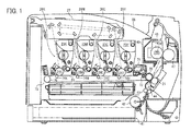
- Fig. 1 is a schematic view illustrating an embodiment of the printer of the present invention.
- the printer includes four process units 26Y, 26C, 26M and 26K for forming yellow, magenta, cyan and black (hereinafter referred to as toner images Y, M, C and K) toner images.
- These use different Y, M, C and K color toners from each other, but have the same configuration and are exchanged at the end of their lives.
- Fig. 1 is a schematic view illustrating an embodiment of the printer of the present invention.
- the printer includes four process units 26Y, 26C, 26M and 26K for forming yellow, magenta, cyan and black (hereinafter referred to as toner images Y, M, C and K) toner images.
- These use different Y, M, C and K color toners from each other, but have the same configuration and are exchanged at the end of their lives.
- the process unit 26K includes a drum-shaped photoreceptor 24K as a latent image bearer, a drum cleaner 83K, a discharger (not illustrated), a charger 25K, an image developer 23K, etc.
- the process unit 26K is detachable from the printer and consumable parts are exchangeable at a tome.
- the charger 25K uniformly charges the surface of the photoreceptor 24K clockwise rotated by an unillustrated driver.
- the uniformly-charged surface of the photoreceptor 24K is irradiated and scanned with a laser beam L to bear a K electrostatic latent image.
- the K electrostatic latent image is developed by the image developer 25K using an unillustrated K toner to form a K toner image.
- the K toner image is intermediately transferred onto an intermediate transfer belt 22 mentioned later.
- the drum cleaner 83K removes an untransferred toner adhering to the surface of the photoreceptor 24K after the intermediate transfer process.
- the discharger discharged a residual charge of the photoreceptor 24K after cleaned.
- the discharge initializes the surface of the photoreceptor 24K to be ready for a following image formation.
- toner images are formed by the same method on the photoreceptors 24Y, 24C and 24M, and they are intermediately transferred onto the intermediate transfer belt 22 mentioned later.
- a cylindrical drum of the photoreceptor 24K is a hollow aluminum tube coated with an organic photosensitive layer. Flanges each having a drum axis are mounted on both ends of the drum in an axial direction to form the photoreceptor 24K.
- the image developer 23K includes a vertically-long hopper 86K containing an unillustrated K toner and a developing part 87K.
- the hopper 86K includes an agitator 88K rotationally driven by an unillustrated driver, an agitation paddle 89K rotationally driven by an unillustrated driver vertically below the agitator 89K, a toner feed roller 80K rotationally driven by an unillustrated driver vertically below the agitation paddle 89K, etc.
- the K toner in the hopper 86K travels to the toner feed roller 80K under its own weight while agitated by rotary drive of the agitator 88K and the agitation paddle 89K.
- the toner feed roller 80K includes a roller formed of a metallic core and a foamed resin coated on the surface thereof, and rotates while the K toner in the hopper 86K adheres thereto.
- the developing part 87K of the image developer 23K includes a developing roller 81K rotating while contacting the photoreceptor 24K and the toner feed roller 80K, a thin layer forming blade 82K contacting the surface thereof, etc.
- the K toner adhering to the toner feed roller 80K in the hopper 86K is fed to the surface of the developing roller 81K at a contact point between the developing roller 81K and the toner feed roller 80K.
- a layer thickness of the K toner fed thereto is regulated thereon when passing a contacting point between the roller and the thin layer forming blade 82K.
- the K toner adheres to a K electrostatic latent image on the surface of the photoreceptor 24K in a developing area which is a contact point between the developing roller 81K and the photoreceptor 24K.
- the K electrostatic latent image is developed to a K toner image.
- the process unit 26K has been explained, using Fig. 2 .
- the process units 26Y, 26C and 26M form Y, C and M toner images on the photoreceptors 24Y, 24C and 24M, respectively by the same process.
- an optical writing unit 27 is located vertically above the process units 26Y, 26C, 26M and 26K.
- the optical writing unit 27 which is a latent image writer optically scans the photoreceptors 24Y, 24C, 24M and 24K in the process units 26Y, 26C, 26M and 26K with a laser beam L emitted from a laser diode, based on image information.
- Y, C, M and K electrostatic latent images are formed on the photoreceptors 24Y, 24C, 24M and 24K, respectively.
- the optical writing unit 27 and the process units 26Y, 26C, 26M and 26K form Y, C, M and K toner images on three or more latent image bearers.
- the optical writing unit 27 irradiates the laser beam (L) emitted from a light source to the photoreceptor through multiple optical lenses and mirrors while polarizing the laser beam in a main scanning direction with an unillustrated polygon mirror rotationally driven by a polygon motor.
- An LED beam emitted from multiple LEDs of an LED array may be used.
- a transfer unit 75 endlessly moving the endless intermediate transfer belt 22 anticlockwise while applying a tension thereto.
- the transfer unit 75 includes a drive roller 76, a tension roller 20, four first transfer rollers 74Y, 74C, 74M and 74K, a second transfer roller 21, a belt cleaner 71, a cleaning backup roller 72, etc.
- the intermediate transfer belt 22 is tensioned by the drive roller 76, the tension roller 20 and the four first transfer rollers 74Y, 74C, 74M and 74K located inside its loop.
- the intermediate transfer belt 22 is endlessly moved anticlockwise by a rotative force of the drive roller 76 rotationally driven by an unillustrated driver anticlockwise.
- the four first transfer rollers 74Y, 74C, 74M and 74K sandwich the endlessly-moved intermediate transfer belt 22 with the photoreceptors 24Y, 24C, 24M and 24K, which forms first transfer nips for Y, C, M and K where the surface of the intermediate transfer belt 22 contacts the photoreceptors 24Y, 24C, 24M and 24K.
- Each of the first transfer rollers 74Y, 74C, 74M and 74K is applied with a first transfer bias by an unillustrated transfer bias electric source to form a transfer electric field between each of the electrostatic latent image on the photoreceptors 24Y, 24C, 24M and 24K and the first transfer rollers 74Y, 74C, 74M and 74K.
- Transfer chargers or brushes can be used instead of the first transfer rollers 74Y, 74C, 74M and 74K.
- the Y toner image formed on the surface of the photoreceptor 24Y in the process unit 26Y enters the first transfer nip Y with the rotation of the photoreceptor 24Y, the Y toner image is first transferred onto the intermediate transfer belt 22 therefrom due to the transfer electric field and a pressure of the nip.
- the intermediate transfer belt 22 on which the Y toner image is first transferred passes the first transfer nips for M, C and K with its endless move, M, C and K toner images on the photoreceptors 24M, 24C and 24K are overlappingly first transferred onto the Y toner image in sequence. This overlapped first transfers form a four-color toner image on the intermediate transfer belt 22.
- the second transfer roller 21 in the transfer unit 75 is located outside the loop of the intermediate transfer belt 22, and sandwiches the intermediate transfer belt 22 with the tension roller 20 located inside the loop, which forms a second transfer nip where the surface of the intermediate transfer belt 22 and the second transfer roller 21 contact each other.
- the second transfer roller 21 is applied with a second transfer bias by an unillustrated transfer bias electric source, which forms a second transfer electric field between the second transfer roller 21 and the earthed tension roller 20.
- a paper feed cassette 41 containing a bundle of papers including multiple recording papers P is located slide-detachably from a chassis of the printer.
- the feed cassette 41 contacts a paper feed roller 42 to the uppermost recording paper P in the bundle of papers, and rotates the roller anticlockwise at a predetermined time to fed the recording paper P to a paper feed path.
- a pair of registration rollers 43 and 44 are located around the end of the paper feed path. As soon as the pair of registration rollers sandwich a recoding paper fed out from the paper feed cassette 41 between the rollers, the both rollers stop rotating. The rollers rotate again to feed the recording paper P to the second transfer nip such that the recording paper P meets the four-color toner image on the intermediate transfer belt 22 in the second transfer nip.
- the four-color toner image on the intermediate transfer belt 22 are secondly transferred onto the recording paper at the second transfer nip at a time due to a second transfer electric field and a pressure of the nip to form a full-color toner image in combination with white of the recording paper P.
- the recording paper P on which the full-color toner image is formed separates from the second transfer roller 21 and the intermediate transfer belt 22 at curvatures. Then, the recording paper P is fed to a fixer 40 through a feed path after transfer.
- the fixer 40 includes a fixing roller 45 including a heat source such as halogen lamps and a pressure roller 47 rotating while contacting the fixing roller 45 at a predetermined pressure, and the fixing roller 45 and the pressure roller 47 form a fixing nip.
- a recording paper fed into the fixer 30 is sandwiched by the fixing nip such that the surface bearing an unfixed toner image adheres to the fixing roller 45. Then, a toner in the toner image is softened with heat and pressure to fix the full-color image.
- the process units 26Y, 26C, 26M and 26K and the optical writing unit 27 form a toner image forming means.
- the printer includes a photoreceptor in the K process unit and a K drive transmitter transmitting a drive force to the developing roller, and photoreceptors in the Y, C and M process units and full-color drive transmitter transmitting a drive force to the developing roller.
- Fig. 3 is a front view illustrating the photoreceptor 24K in the process unit 26K and a drive transmitter 1K transmitting a drive force to a developing roller 81K
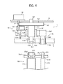
- Fig. 4 is a cross-sectional view illustrating the drive transmitter 1K and its circumference.
- the drive transmitter 1K is located between a unit side plate 13 and a support plate 12.
- the drive transmitter 1K includes a first drive transmitting part transmitting a drive force to the photoreceptor 24K as a first rotator, and a second drive transmitting part transmitting a drive force to the developing roller as a second rotator.
- the first drive transmitting part includes a photoreceptor gear 4K transmitting a drive force of a drive motor 2K to the photoreceptor 24k
- the second drive transmitting part includes a developing drive gear array transmitting a drive force of a drive motor 2K to the developing roller 81K.
- the developing drive gear array is located so as to be included in a width in an axial direction to prevent the drive transmitter 1K from expanding in an axial direction.
- the drive motor 2K is located at the back side of the support plate 12 and penetrates its rotational axis through an unillustrated hole formed on the support plate 12 from the back side such that a tip of the rotational axis 2aK is located between the support plate 12 and the unit side plate 13 while the motor unit is located out side of the support plate 12.
- the rotational axis of the drive motor 2K is directly subjected to gear cutting to form a drive gear 3K.
- the photoreceptor gear 4K as a drive transmitting member is located above the rotational axis of the drive motor 2K.
- the photoreceptor gear 4K includes a disk-shaped gear 4aK, a first axis 4bK as a first rotational axis, a convex coupling 4cK as an engager and a second axis 4dK formed of the same material such as resins in a single piece.
- the photoreceptor gear 4K including the gear 4aK, the axis 4bK and the convex coupling 4cK in a single piece is free from eccentricity between the gear or the convex coupling and the rotational axis. Therefore, the photoreceptor drum 24K is free from speed variation due to the eccentricity.
- the second axis 4dK is located at a rotational center of a surface facing the support plate 12 of the gear 4aK, and rotationally supported thereby.
- the first axis 4bK is located at a rotational center of a surface facing the unit side plate 13 of the gear 4aK, and the convex coupling 4cK is located at the top thereof.
- the gear 4aK of the photoreceptor gear 4K has a radius larger than a length from an axial center of the photoreceptor 24K to an axial center of the developing roller 81K, and is engaged with the drive gear 3K.
- This can make one step speed reduction, a pitch error on the surface of the photoreceptor for one gear tooth small, and decrease uneven image density (banding) in a sub-scanning direction. Further, the one step speed reduction decreases parts and costs, and transmission error due to engaging error and eccentricity.
- the speed reduction ratio is determined based on a speed range from which high efficiency and high rotation preciseness can be obtained, from a relationship between an aimed speed of the photoreceptor 24K and motor properties.
- the convex coupling 4cK is a spline axis, on the outer circumference of which teeth are formed.
- the photoreceptor gear 4K is formed of a resin comparatively having a small friction coefficient such as polyacetal resins.
- the developing drive gear array in the second drive transmitting part includes a clutch 7K, an idler gear 9K and a developing gear 10K.
- the clutch 7K includes an input gear 7aK engaged with the drive gear 3K, an output gear 7bK engaged with the idler gear 9K and a clutch axis 7cK.
- the clutch axis 7cK is rotatably supported by the support plate 12 and the unit side plate 13.
- the clutch 7K when an unillustrated controller turns on or off providing electricity thereto, transmits a rotary drive force of the input gear 7aK to the clutch axis 7cK or idles the input gear 7aK. Specifically, when an electricity is provided to the clutch 7K, the rotary drive force of the input gear 7aK is transmitted to the clutch axis 7cK to rotate the output gear 7bK.
- the input gear 7aK idles on the clutch axis 7cK even when the drive motor 2 rotates, and the output gear 7bK stops rotating.
- the idler gear 9K has a through-hole, and a cylinder 11aK of a holding member 11K is inserted into the through-hole to rotatably hold the idler gear 9K on the outer circumferential surface of the cylinder 11aK.
- the developing gear 10K includes a gear 10aK engaged with the idler gear 9K and a cylindrical concave coupling 10bK as a second rotational axis.
- the developing gear 10K is rotatably held by the unit side plate 13 because an outer circumferential surface of the cylindrical concave coupling 10bK is rotatably engaged with a bearing 13bK located on the unit side plate 13.
- the idler gear 9K has a rotational center identical with that of the photoreceptor gear 4K, the through-hole of the idler gear 9K can be small and decrease of rigidity of the idler gear can be prevented.
- the holding member 11K holding the idler gear 9K is formed of a resin comparatively having a small friction coefficient such as polyacetal resins, is located on the unit side plate 13.
- the cylinder 11aK of the holding member 11K has a motor side inner diameter larger than an outer diameter of the first axis 4bK of the photoreceptor gear 4K, which penetrates an inner circumferential surface of the cylinder 11aK of the holding member 11K with a gap therebetween.
- a fall down regulator 11eK having an inner diameter smaller than that of the cylinder 11aK at the photoreceptor side relative thereto.
- the fall down regulator 11eK faces the convex coupling 4cK of the photoreceptor gear 4K, and the convex coupling 4cK hits the fall down regulator 11eK to prevent the photoreceptor gear 4K from falling down. Therefore, the convex coupling 4cK is smoothly engaged with the concave coupling 10bK, and the process unit 26K can smoothly be installed in the apparatus. Further, the fall down regulator 11eK has an inner diameter smaller than an outer diameter of the first axis 4bK of the photoreceptor gear 4K.
- an end surface of the first axis 4bK of the photoreceptor gear 4K hits a level difference 11dk formed between an inner circumferential surface of the cylinder 11aK and the fall down regulator 11eK, which prevents the photoreceptor gear 4K from moving in an axial direction.
- the level difference 11dk works as a movement regulator. This prevents the second axis 4dK of the photoreceptor gear from releasing from the support plate 12.
- a contact surface 11cK contacting a surface of the unit side plate 12 at the motor side and a joint projection 11bk joining a positioning hole 13aK.
- the holding member 11K makes the joint projection 11bk join the positioning hole 13aK and contacts the contact surface 11cK to the motor side surface of the unit side plate 13 to rotatably fit the idler gear 9K to the apparatus with a gap between the idler gear 9K and the first axis 4bK.
- a concave coupling 84K including inner teeth on its inner circumferential surface is located at the unit side plate 13 side of the photoreceptor 24K.
- a bearing 26bK formed on a case 26aK of the process unit 26K joins an outer circumferential surface of the concave coupling 84K, and a part of the bearing 26bK projects from the case 26aK.
- the convex coupling 4cK of the photoreceptor gear 4K and the concave coupling 84K at the photoreceptor 24K side have the following advantage, compared with a concave coupling of the photoreceptor gear and a convex coupling at the photoreceptor side.
- the convex coupling projects from the case 26aK of the process unit and the couplings are engaged with each other apart from the case 26aK.
- the couplings are engaged with each other at the case 26aK side.
- the couplings are engaged with each other at a position closer to the photoreceptor than a convex coupling at the photoreceptor side, which prevents the photoreceptor 24K from oscillating.
- a rotational axis 81aK of the developing roller 81K is rotatably held by a bearing 26cK formed on the case 26aK, and a top thereof projects from the case 26aK.
- a spline axial member 85K as a convex coupling is formed on a top of the rotational axis 81aK of the developing roller 81K at the unit side plate side.
- the developing roller is not so influenced by speed variation as a photoreceptor, and the high-cost concave coupling the inner teeth of which is difficult to form is located in the apparatus to decrease the cost of the process unit 26K.
- the process unit 26K When the process unit 26K is installed in the apparatus, a part of the bearing 26bK supporting the photoreceptor 24K projecting from the case 26aK is joined to the positioning hole 13aK of the unit side plate 13. Thus, the process unit 26K is positioned in the apparatus. Then, the teeth of the convex coupling 4cK of the photoreceptor gear 4K are engaged with the inner teeth of the concave coupling 84K formed on the photoreceptor 24K. Further, the teeth of the spline axial member 85K formed on the axis 81aK of the developing roller 81K are engaged with the inner teeth of the concave coupling 10bK if the developing gear 10K.
- the concave coupling 84K formed on the photoreceptor 24K can smoothly be inserted into the convex coupling 4cK of the photoreceptor gear 4K, and the process unit 26K can smoothly be installed in the apparatus.
- a drive force of the drive motor 2K is transmitted to the photoreceptor 24K through the drive gear 3K, the photoreceptor gear 4K (the gear 4aK, the first axis 4bK and the convex coupling 4cK), and to the developing roller 81K through the drive gear 3K, the clutch 7K (the input gear 7aK and the output gear 7bK), the idler gear 9K and the developing gear 10K (the gear 10aK and the convex coupling 10bK).
- the idler gear 9K scrapes an outer circumferential surface of the cylinder 11aK of the holding member 11K, but abrasions of the idler gear 9K and the cylinder 11aK can be prevented because the idler gear 9K and the holding member 11K are formed of a resin comparatively having a small friction coefficient.
- a ball bearing may be formed between the idler gear 9K scrapes the outer circumferential surface of the cylinder 11aK of the holding member 11K to rotatably hold the idler gear 9K on the holding member 11K.
- the idler gear 9K held by the holding member 11K is preferably a gear being the same as a gear having the least revolutions per minute which is one of the multiple gears in the developing drive gear array.
- An inner circumferential surface of the idler gear 9K held by the holding member 11K scrapes the outer circumferential surface of the cylinder 11aK of the holding member 11K, and a scrape resistance inevitably occurs.
- the idler gear 9K held by the holding member 11K has the least revolutions per minute, the scrape distance with the outer circumferential surface of the cylinder 11aK per one revolution of the developing roller can be shortest. This can prevent deterioration of transmission efficiency and heat generation.
- the idler gear 9K may be a gear being the same as a gear having the least torque which is one of the multiple gears in the developing drive gear array. This can prevent scrape resistance with outer circumferential surface of the cylinder 11aK of the holding member 11K, and deterioration of transmission efficiency and heat generation.
- the first axis 4bK of the photoreceptor gear 4K penetrates the cylinder 11aK of the holding member 11K holding the idler gear 9K with a gap. Therefore, a load variation of the developing roller 81K is not transmitted to the photoreceptor gear 4K through the idler gear 9K and the holding member 11K. As a result, due to backlash, etc. between the photoreceptor gear 4K and the drive gear 3K, a drive force from the drive gear 3K is not transmitted to the photoreceptor gear 4K for a moment, which prevents speed variation of the photoreceptor 24K.
- the holding member 11K preferably has a linear expansion coefficient smaller than that of the photoreceptor gear.
- the holding member 11K is easy to heat up because the idler gear scrapes the holding member 11K. Therefore, the holding member 11K having a linear expansion coefficient smaller than that of the photoreceptor gear prevents itself from thermally expanding to contact the photoreceptor gear.
- the idler gear 9K is located closer to the process unit 26K than the gear 4aK of the photoreceptor gear 4K.
- the gear 4aK of the photoreceptor gear 4K has a radius longer than a distance between an axial center of the photoreceptor 24K and an axial center of the developing roller 81K.
- a rotational axis is needed to locate outside the gear 4aK of the photoreceptor gear, and a first relay gear engaging with the idler gear 9K and a second relay gear engaging with the gear 10aK of the developing gear need be formed on the rotational gear.
- the idler gear 9K located closer to the process unit 26K than the gear 4aK of the photoreceptor gear 4K can directly be engaged with the gear 10aK of the developing gear 10K, and can reduce the number of parts and downsize the apparatus compared with the idler gear 9K located closer to the motor than the gear 4aK of the photoreceptor gear 4K.
- the gear 4aK of the photoreceptor gear can be engaged with a bedrock of the drive gear 3K. Therefore, a deflection of the drive gear 3K is difficult to occur, and a rotational drive force of the motor can precisely be transmitted from the drive gear to the gear 4aK of the photoreceptor gear.
- Fig. 5 is a front view of the full-color drive transmitter 1YCM and Fig. 6 is a cross-sectional view of the full-color drive transmitter 1YCM and its circumference. Only features of the full-color drive transmitter 1YCM are explained, and explanations of the same configurations as those of the K drive transmitter are omitted.
- the full-color drive transmitter 1YCM is located between the unit side plate 13 and the support plate 12.
- the full-color drive transmitter 1YCM includes a first drive transmitting part including a full-color photoreceptor gear array and transmitting a drive force of a full-color photoreceptor drive motor 2a as a drive source to each of photoreceptors 24Y, 24C and 24M, and a second drive transmitting part including a full-color developing drive gear array and transmitting a drive force of a developing drive motor 2b as a drive source to each of developing rollers 81Y, 81C and 81M.
- the full-color photoreceptor gear array of the first drive transmitting part includes photoreceptor gears 4Y, 4C and 4M and a photoreceptor idler gear 17.
- Each of the photoreceptor gears 4Y, 4C and 4M has the same configuration as that of the photoreceptor gear 4K.
- a gear 4aM of the photoreceptor gear 4M and a gear 4aC of the photoreceptor gear 4C are engaged with a drive gear 3a formed on a rotational axis of the full-color photoreceptor drive motor 2a.
- the photoreceptor idler gear 17 is located between the photoreceptor gear 4Y and the photoreceptor gear 4C, and engaged with a gear 4aY of the photoreceptor gear 4Y and a gear 4aC of the photoreceptor gear 4C.
- a drive force of the full-color photoreceptor drive motor 2a is transmitted to the photoreceptor 24M through the drive gear 3 a and the photoreceptor gear 4M; to the photoreceptor 24C from the drive gear 3 a through the photoreceptor gear 4C; and to the photoreceptor 24Y from the drive gear 3a through the photoreceptor gear 4C, the idler gear 17 and the photoreceptor gear 4Y in this order.
- a first relay gear 14 and a second relay gear 15 are engaged with a developing drive gear 3b formed on a rotational axis of the developing drive motor 2b.
- An idler gear 9Y is engaged with the first relay gear 14.
- the idler gear 9Y is rotatably held on an outer circumferential surface of a cylinder 11aY of a holding member 11Y as the idler gear 9K is, and engaged with a developing gear 10Y
- An idler gear 9C is engaged with the second relay gear 15 and rotatably held on an outer circumferential surface of a cylinder 11aC of a holding member 11C.
- a developing gear 10C and a third relay gear 16 are engaged with the idler gear 9C.
- An idler gear 9M is engaged with the third relay gear 16 and rotatably held on an outer circumferential surface of a cylinder 11aM of a holding member 11M.
- the idler gear 9M is engaged with a developing gear 10M.
- Each of the developing gears 10Y, 10C and 10M has the same configuration as that of the developing gear 10K.
- a drive force of the full-color photoreceptor drive motor 2b is transmitted to the developing roller 81Y through the developing drive gear 3b, the first relay gear 14, the idler gear 9Y and the developing gear 10Y; to the developing roller 81C through the developing drive gear 3b, the idler gear 9C and the developing gear 10C; and to the developing roller 81M through the developing drive gear 3b, the second relay gear 15, the idler gear 9C, the third relay gear 16, the idler gear 9M and the developing gear 10M.
- Each of first axes 4bY, 4bC and 4bM of the photoreceptor gears 4Y, 4C and 4M penetrates each of the cylinders 11aY, 11aC and 11aM of the holding members 11Y, 11C and 11M with a gap. Therefore, a load variation of each of the developing rollers 81Y, 81C and 81M is not transmitted to each of the photoreceptor gears 4Y, 4C and 4M to prevent speed variations of the photoreceptors 24Y, 24C and 24M.
- the idler gears 9Y, 9C and 9M located closer to the unit than the gears 4aY, 4aC and 4aM of the photoreceptor gears can be engaged with gears 10aY, 10aC and 10aM of the developing gears even when each of the gears 4aY, 4aC and 4aM has a radius longer than a distance from an axial center of the photoreceptor to an axial center of the developing roller. This can reduce the number of parts and downsize the apparatus. Further, the gear 4aM of the photoreceptor gear 4M and the gear 4aC of the photoreceptor gear 4C can be engaged with a bedrock of the drive gear 3a. Therefore, a rotational drive force of the motor can precisely be transmitted from the drive gear 3a to the gears 4aM and 4aC.
- the full-color drive transmitter 1YCM has a drive source giving a drive force to the developing rollers 81Y, 81C and 81M and another drive source giving a drive force to the photoreceptors 24Y, 24C and 24M. Therefore, a route for transmitting the drive force to the photoreceptors 24Y, 24C and 24M and a route for transmitting the drive force to the developing rollers 81Y, 81C and 81M can completely be separated from each other. Therefore, a load of each of the developing rollers 81Y, 81C and 81M does not influence on rotation of each of the photoreceptors 24Y, 24C and 24M, which prevents variation of rotation speed thereof.
- the full-color developing drive gear array within a width of an axial direction of each of the photoreceptor gears 4Y, 4C and 4M prevents the full-color drive transmitter 1YCM from expanding in an axial direction.
- the number of rotations and load torque of each of the idler gears 9Y, 9C and 9M held by the holding members 11Y, 11C and 11M are preferably smaller than those of the other gears in the full-color developing drive gear array, which prevents deterioration of transmission efficiency and heat generation.
- Each of the holding members 11Y, 11C and 11M having a linear expansion coefficient smaller than that of each of the photoreceptor gears 4Y, 4M and 4C prevents itself from thermally expanding to contact each of the photoreceptor gears 4Y, 4M and 4C.
- the drive transmitter transmits a drive force of a drive motor to the photoreceptor 24 and the developing roller 81 of the process unit, and may transmit a drive force of a drive motor to the charging roller 25and the feed roller 80 instead of the developing roller 81. Further, the drive transmitter may transmit a drive force transmitted to the developing roller 81 to the charging roller 25and the feed roller 80. In addition, the drive transmitter may have three or more drive transmitting parts.
- the first axis of the photoreceptor gear may penetrate through multiple gears with gaps, respectively. Further, a single drive source may transmit a drive force to each of the first and second rotators.
- the first axis 4b rotating with a photoreceptor gear 4a which is a gear of the first drive transmitting part and penetrating through the idler gear with a gap can prevent speed variation of the photoreceptor.
- a projected area of the gear 4a in an axial direction can effectively used, and the apparatus can be downsized.
- the first drive transmitting part includes a gear engaging with a drive gear of a drive source, a first rotational axis extending from a rotational center of the gear, and a photoreceptor gear 4 formed on the top of the first rotational axis including an engaging means engaging with a first rotator. Therefore, there is no installation eccentricity of a gear and a convex coupling to the first rotational axis, which eliminates speed variation of the photoreceptor 24K.
- the developing drive gear array with an axial direction of the photoreceptor gear 4 can prevent the drive transmitter from enlarging in an axial direction.
- the developing gear array which is a drive transmitting part gear besides the first drive transmitting part located closer to the rotator than the first drive transmitting part gear, when the photoreceptor gear 4 has a larger diameter, can reduce the number of gears and parts more than the developing gear array located closer to the motor than the first drive transmitting part gear. Further, enlargement of the apparatus can be prevented, and the photoreceptor gear 4 can be engaged with a bedrock of the drive gear 3K to precisely drive the photoreceptor.
- a holding member 11 rotatably holds an idler gear 9 the first axis of the photoreceptor gear 4 penetrates with a gap.
- the holding member 11 rotatably holds the idler gear on its outer circumferential surface and its inner circumferential surface has a cylinder 11a the axis of the photoreceptor penetrates with a predetermined gap.
- the idler gear is rotatably fixed thereon with a gap from the first axis penetrating through the gear.
- a level difference 11d as a regulation member regulates movement of the photoreceptor gear 4 in an axial direction. This prevents the photoreceptor gear 4 from releasing from the support plate 12.
- a fall down regulator 11e regulating fall down of the photoreceptor gear 4 can smoothly engage a convex coupling 4c thereof with a concave coupling 84 of the photoreceptor, and can smoothly place a process unit 26 in the apparatus.
- the holding member 11 having a linear expansion coefficient smaller than that of the photoreceptor gear 4 can prevent itself from contacting the photoreceptor gear even when thermally expanded with heat due to scrape with the idler gear 9. This prevents the photoreceptor gear 4 from scraping the holding member 11 and varying in its rotational speed.
- a rotational center of the idler gear and a rotational center of the photoreceptor gear located at the same position can make a penetration hole of the idler gear small, which prevents the idler gear from enlarging and weakening.
- the engaging coupling of the photoreceptor gear is a convex coupling engaging with a concave coupling formed on the photoreceptor, which makes an engaging position of the couplings closer to the photoreceptor and prevents the photoreceptor from oscillating better than a convex coupling of the photoreceptor and a concave coupling of the photoreceptor gear.
- a rotational load of the developing roller does not influence upon the photoreceptor. This can prevent the photoreceptor from varying its rotational speed.
- the drive transmitter in an image forming apparatus including multiple rotators can prevent the apparatus from enlarging. Further, when a rotator to which the first drive transmitting part transmits a drive force is a photoreceptor bearing an image, speed variation of the photoreceptor and uneven image density can be prevented well.
- the drive transmitter located in the apparatus can make the process unit less expensive than the drive transmitter located in the process unit.
Landscapes
- Physics & Mathematics (AREA)
- General Physics & Mathematics (AREA)
- Engineering & Computer Science (AREA)
- General Engineering & Computer Science (AREA)
- Computer Vision & Pattern Recognition (AREA)
- Mechanical Engineering (AREA)
- Electrophotography Configuration And Component (AREA)
Abstract
Description
- The present invention relates to a drive transmitter and an image forming apparatus.
- Image forming apparatuses, e.g., printers, facsimiles and copiers include multiple rotators such as photoreceptors and developing rollers that are rotated to form images.
- Japanese published unexamined application No.
2003-295552 JP-2003-295552-A - In this drive transmitter, a thin-teeth gear, which is part of the drive gear train of the second drive transmitting part, is fixed to the same rotation shaft to which the photoreceptor gear is fixed. Thus, a projected area of the photoreceptor gear in an axial direction (overlapping the photoreceptor gear when axially seen) can effectively be used, and the drive transmitter can be downsized.
- However, a rotation load of the fixing roller and the registration roller is also transmitted thereto, resulting in possible speed variation of the photoreceptor.
- Accordingly, an object of the present invention is to provide a downsizable drive transmitter capable of controlling speed variation of a first rotator to which a first rotation shaft transmits a drive force.
- Another object of the present invention is to provide an image forming apparatus using the drive transmitter.
- These objects and other objects of the present invention, either individually or collectively, have been satisfied by the discovery of a drive transmitter, comprising:
- a first rotational axis configured to transmit a drive force of a drive source to a first rotator,
- a second rotational axis configured to transmit a drive force of the drive source to a second rotator, and
- an idler gear configured to transmit a drive force to the second rotational axis;
- These and other objects, features and advantages of the present invention will become apparent upon consideration of the following description of the preferred embodiments of the present invention taken in conjunction with the accompanying drawings.
- Various other objects, features and attendant advantages of the present invention will be more fully appreciated as the same becomes better understood from the detailed description when considered in connection with the accompanying drawings in which like reference characters designate like corresponding parts throughout and wherein:
-
Fig. 1 is a schematic view illustrating an embodiment of the printer of the present invention; -
Fig. 2 is a schematic view illustrating a process unit; -
Fig. 3 is a front view of the black color drive transmitter; -
Fig. 4 is a cross-sectional view of the black color drive transmitter and its circumference; -
Fig. 5 is a front view of the full-color drive transmitter; and -
Fig. 6 is a cross-sectional view of the full-color drive transmitter and its circumference; - The present invention provides a downsizable drive transmitter capable of controlling speed variation of a first rotator to which a first rotation shaft transmits a drive force.
- More particularly, the present invention relates to a drive transmitter, comprising:
- a first rotational axis configured to transmit a drive force of a drive source to a first rotator,
- a second rotational axis configured to transmit a drive force of the drive source to a second rotator, and
- an idler gear configured to transmit a drive force to the second rotational axis;
- An embodiment of electrophotographic printer (hereinafter referred to as a printer) is explained as the image forming apparatus of the present invention.
- First, a basic configuration of the printer is explained.
Fig. 1 is a schematic view illustrating an embodiment of the printer of the present invention. InFig. 1 , the printer includes fourprocess units Fig. 2 shows, theprocess unit 26K includes a drum-shaped photoreceptor 24K as a latent image bearer, adrum cleaner 83K, a discharger (not illustrated), acharger 25K, animage developer 23K, etc. Theprocess unit 26K is detachable from the printer and consumable parts are exchangeable at a tome. - The
charger 25K uniformly charges the surface of thephotoreceptor 24K clockwise rotated by an unillustrated driver. The uniformly-charged surface of thephotoreceptor 24K is irradiated and scanned with a laser beam L to bear a K electrostatic latent image. The K electrostatic latent image is developed by theimage developer 25K using an unillustrated K toner to form a K toner image. Then, the K toner image is intermediately transferred onto anintermediate transfer belt 22 mentioned later. Thedrum cleaner 83K removes an untransferred toner adhering to the surface of thephotoreceptor 24K after the intermediate transfer process. The discharger discharged a residual charge of thephotoreceptor 24K after cleaned. The discharge initializes the surface of thephotoreceptor 24K to be ready for a following image formation. In the other process units, i.e., 26Y, 26C and 26M, toner images are formed by the same method on thephotoreceptors intermediate transfer belt 22 mentioned later. A cylindrical drum of thephotoreceptor 24K is a hollow aluminum tube coated with an organic photosensitive layer. Flanges each having a drum axis are mounted on both ends of the drum in an axial direction to form thephotoreceptor 24K. - The
image developer 23K includes a vertically-long hopper 86K containing an unillustrated K toner and a developingpart 87K. Thehopper 86K includes anagitator 88K rotationally driven by an unillustrated driver, anagitation paddle 89K rotationally driven by an unillustrated driver vertically below theagitator 89K, atoner feed roller 80K rotationally driven by an unillustrated driver vertically below theagitation paddle 89K, etc. The K toner in thehopper 86K travels to thetoner feed roller 80K under its own weight while agitated by rotary drive of theagitator 88K and theagitation paddle 89K. Thetoner feed roller 80K includes a roller formed of a metallic core and a foamed resin coated on the surface thereof, and rotates while the K toner in thehopper 86K adheres thereto. - The developing
part 87K of theimage developer 23K includes a developingroller 81K rotating while contacting thephotoreceptor 24K and thetoner feed roller 80K, a thinlayer forming blade 82K contacting the surface thereof, etc. The K toner adhering to thetoner feed roller 80K in thehopper 86K is fed to the surface of the developingroller 81K at a contact point between the developingroller 81K and thetoner feed roller 80K. A layer thickness of the K toner fed thereto is regulated thereon when passing a contacting point between the roller and the thinlayer forming blade 82K. After regulated, the K toner adheres to a K electrostatic latent image on the surface of thephotoreceptor 24K in a developing area which is a contact point between the developingroller 81K and thephotoreceptor 24K. Thus, the K electrostatic latent image is developed to a K toner image. - The
process unit 26K has been explained, usingFig. 2 . Theprocess units photoreceptors - In
Fig. 1 , anoptical writing unit 27 is located vertically above theprocess units optical writing unit 27 which is a latent image writer optically scans thephotoreceptors process units photoreceptors optical writing unit 27 and theprocess units - The
optical writing unit 27 irradiates the laser beam (L) emitted from a light source to the photoreceptor through multiple optical lenses and mirrors while polarizing the laser beam in a main scanning direction with an unillustrated polygon mirror rotationally driven by a polygon motor. An LED beam emitted from multiple LEDs of an LED array may be used. - Vertically below the
process units transfer unit 75 endlessly moving the endlessintermediate transfer belt 22 anticlockwise while applying a tension thereto. Besides theintermediate transfer belt 22, thetransfer unit 75 includes adrive roller 76, atension roller 20, fourfirst transfer rollers second transfer roller 21, abelt cleaner 71, acleaning backup roller 72, etc. - The
intermediate transfer belt 22 is tensioned by thedrive roller 76, thetension roller 20 and the fourfirst transfer rollers intermediate transfer belt 22 is endlessly moved anticlockwise by a rotative force of thedrive roller 76 rotationally driven by an unillustrated driver anticlockwise. - The four
first transfer rollers intermediate transfer belt 22 with thephotoreceptors intermediate transfer belt 22 contacts thephotoreceptors - Each of the
first transfer rollers photoreceptors first transfer rollers first transfer rollers - When a Y toner image formed on the surface of the
photoreceptor 24Y in theprocess unit 26Y enters the first transfer nip Y with the rotation of thephotoreceptor 24Y, the Y toner image is first transferred onto theintermediate transfer belt 22 therefrom due to the transfer electric field and a pressure of the nip. When theintermediate transfer belt 22 on which the Y toner image is first transferred passes the first transfer nips for M, C and K with its endless move, M, C and K toner images on thephotoreceptors intermediate transfer belt 22. - The
second transfer roller 21 in thetransfer unit 75 is located outside the loop of theintermediate transfer belt 22, and sandwiches theintermediate transfer belt 22 with thetension roller 20 located inside the loop, which forms a second transfer nip where the surface of theintermediate transfer belt 22 and thesecond transfer roller 21 contact each other. Thesecond transfer roller 21 is applied with a second transfer bias by an unillustrated transfer bias electric source, which forms a second transfer electric field between thesecond transfer roller 21 and the earthedtension roller 20. - Vertically below the
transfer unit 75, apaper feed cassette 41 containing a bundle of papers including multiple recording papers P is located slide-detachably from a chassis of the printer. Thefeed cassette 41 contacts apaper feed roller 42 to the uppermost recording paper P in the bundle of papers, and rotates the roller anticlockwise at a predetermined time to fed the recording paper P to a paper feed path. - A pair of
registration rollers 43 and 44 are located around the end of the paper feed path. As soon as the pair of registration rollers sandwich a recoding paper fed out from thepaper feed cassette 41 between the rollers, the both rollers stop rotating. The rollers rotate again to feed the recording paper P to the second transfer nip such that the recording paper P meets the four-color toner image on theintermediate transfer belt 22 in the second transfer nip. - The four-color toner image on the
intermediate transfer belt 22 are secondly transferred onto the recording paper at the second transfer nip at a time due to a second transfer electric field and a pressure of the nip to form a full-color toner image in combination with white of the recording paper P. After passing the second transfer nip, the recording paper P on which the full-color toner image is formed separates from thesecond transfer roller 21 and theintermediate transfer belt 22 at curvatures. Then, the recording paper P is fed to afixer 40 through a feed path after transfer. - A residual toner untransferred onto a recording paper P adheres to the
intermediate transfer belt 22 after passing the second transfer nip. Thebelt cleaner 71 contacting the surface of theintermediate transfer belt 22 removes the residual toner therefrom. The cleaningbackup roller 72 located inside the loop of theintermediate transfer belt 22 assist thebelt cleaner 71 to clean the belt from the inside of the loop. - The
fixer 40 includes a fixingroller 45 including a heat source such as halogen lamps and apressure roller 47 rotating while contacting the fixingroller 45 at a predetermined pressure, and the fixingroller 45 and thepressure roller 47 form a fixing nip. A recording paper fed into the fixer 30 is sandwiched by the fixing nip such that the surface bearing an unfixed toner image adheres to the fixingroller 45. Then, a toner in the toner image is softened with heat and pressure to fix the full-color image. - An input operation to an unillustrated operation portion formed of ten-key, etc. and a control signal transmitted from an unillustrated personal computer specify the one side print mode, a recording paper P discharged from the
fixer 40 is discharged out of the apparatus as it is. Then, the recording paper P is stacked on astack part 56 which is an upper surface of a cover on the top of the chassis. - The
process units optical writing unit 27 form a toner image forming means. - Next, the photoreceptor in the process unit and a drive transmitter transmitting a drive force of a motor as a drive source to the developing roller are explained.
- The printer includes a photoreceptor in the K process unit and a K drive transmitter transmitting a drive force to the developing roller, and photoreceptors in the Y, C and M process units and full-color drive transmitter transmitting a drive force to the developing roller.
-
Fig. 3 is a front view illustrating thephotoreceptor 24K in theprocess unit 26K and adrive transmitter 1K transmitting a drive force to a developingroller 81K, andFig. 4 is a cross-sectional view illustrating thedrive transmitter 1K and its circumference. - As
Fig. 4 shows, thedrive transmitter 1K is located between aunit side plate 13 and asupport plate 12. Thedrive transmitter 1K includes a first drive transmitting part transmitting a drive force to thephotoreceptor 24K as a first rotator, and a second drive transmitting part transmitting a drive force to the developing roller as a second rotator. The first drive transmitting part includes aphotoreceptor gear 4K transmitting a drive force of adrive motor 2K to the photoreceptor 24k, and the second drive transmitting part includes a developing drive gear array transmitting a drive force of adrive motor 2K to the developingroller 81K. The developing drive gear array is located so as to be included in a width in an axial direction to prevent thedrive transmitter 1K from expanding in an axial direction. - The
drive motor 2K is located at the back side of thesupport plate 12 and penetrates its rotational axis through an unillustrated hole formed on thesupport plate 12 from the back side such that a tip of the rotational axis 2aK is located between thesupport plate 12 and theunit side plate 13 while the motor unit is located out side of thesupport plate 12. The rotational axis of thedrive motor 2K is directly subjected to gear cutting to form adrive gear 3K. - Above the rotational axis of the
drive motor 2K, thephotoreceptor gear 4K as a drive transmitting member is located. Thephotoreceptor gear 4K includes a disk-shaped gear 4aK, a first axis 4bK as a first rotational axis, a convex coupling 4cK as an engager and a second axis 4dK formed of the same material such as resins in a single piece. Thephotoreceptor gear 4K including the gear 4aK, the axis 4bK and the convex coupling 4cK in a single piece is free from eccentricity between the gear or the convex coupling and the rotational axis. Therefore, thephotoreceptor drum 24K is free from speed variation due to the eccentricity. - The second axis 4dK is located at a rotational center of a surface facing the
support plate 12 of the gear 4aK, and rotationally supported thereby. The first axis 4bK is located at a rotational center of a surface facing theunit side plate 13 of the gear 4aK, and the convex coupling 4cK is located at the top thereof. - The gear 4aK of the
photoreceptor gear 4K has a radius larger than a length from an axial center of thephotoreceptor 24K to an axial center of the developingroller 81K, and is engaged with thedrive gear 3K. This can make one step speed reduction, a pitch error on the surface of the photoreceptor for one gear tooth small, and decrease uneven image density (banding) in a sub-scanning direction. Further, the one step speed reduction decreases parts and costs, and transmission error due to engaging error and eccentricity. The speed reduction ratio is determined based on a speed range from which high efficiency and high rotation preciseness can be obtained, from a relationship between an aimed speed of thephotoreceptor 24K and motor properties. The convex coupling 4cK is a spline axis, on the outer circumference of which teeth are formed. Thephotoreceptor gear 4K is formed of a resin comparatively having a small friction coefficient such as polyacetal resins. - The developing drive gear array in the second drive transmitting part includes a clutch 7K, an
idler gear 9K and a developinggear 10K. - The clutch 7K includes an input gear 7aK engaged with the
drive gear 3K, an output gear 7bK engaged with theidler gear 9K and a clutch axis 7cK. The clutch axis 7cK is rotatably supported by thesupport plate 12 and theunit side plate 13. The clutch 7K, when an unillustrated controller turns on or off providing electricity thereto, transmits a rotary drive force of the input gear 7aK to the clutch axis 7cK or idles the input gear 7aK. Specifically, when an electricity is provided to the clutch 7K, the rotary drive force of the input gear 7aK is transmitted to the clutch axis 7cK to rotate the output gear 7bK. When an electricity is not provided thereto, the input gear 7aK idles on the clutch axis 7cK even when the drive motor 2 rotates, and the output gear 7bK stops rotating. - The
idler gear 9K has a through-hole, and a cylinder 11aK of a holdingmember 11K is inserted into the through-hole to rotatably hold theidler gear 9K on the outer circumferential surface of the cylinder 11aK. The developinggear 10K includes a gear 10aK engaged with theidler gear 9K and a cylindrical concave coupling 10bK as a second rotational axis. The developinggear 10K is rotatably held by theunit side plate 13 because an outer circumferential surface of the cylindrical concave coupling 10bK is rotatably engaged with a bearing 13bK located on theunit side plate 13. - Since the
idler gear 9K has a rotational center identical with that of thephotoreceptor gear 4K, the through-hole of theidler gear 9K can be small and decrease of rigidity of the idler gear can be prevented. - The holding
member 11K holding theidler gear 9K is formed of a resin comparatively having a small friction coefficient such as polyacetal resins, is located on theunit side plate 13. The cylinder 11aK of the holdingmember 11K has a motor side inner diameter larger than an outer diameter of the first axis 4bK of thephotoreceptor gear 4K, which penetrates an inner circumferential surface of the cylinder 11aK of the holdingmember 11K with a gap therebetween. A fall down regulator 11eK having an inner diameter smaller than that of the cylinder 11aK at the photoreceptor side relative thereto. The fall down regulator 11eK faces the convex coupling 4cK of thephotoreceptor gear 4K, and the convex coupling 4cK hits the fall down regulator 11eK to prevent thephotoreceptor gear 4K from falling down. Therefore, the convex coupling 4cK is smoothly engaged with the concave coupling 10bK, and theprocess unit 26K can smoothly be installed in the apparatus. Further, the fall down regulator 11eK has an inner diameter smaller than an outer diameter of the first axis 4bK of thephotoreceptor gear 4K. Therefore, an end surface of the first axis 4bK of thephotoreceptor gear 4K hits a level difference 11dk formed between an inner circumferential surface of the cylinder 11aK and the fall down regulator 11eK, which prevents thephotoreceptor gear 4K from moving in an axial direction. Namely, the level difference 11dk works as a movement regulator. This prevents the second axis 4dK of the photoreceptor gear from releasing from thesupport plate 12. - At the photoreceptor side of the holding
member 11K, a contact surface 11cK contacting a surface of theunit side plate 12 at the motor side and a joint projection 11bk joining a positioning hole 13aK. The holdingmember 11K makes the joint projection 11bk join the positioning hole 13aK and contacts the contact surface 11cK to the motor side surface of theunit side plate 13 to rotatably fit theidler gear 9K to the apparatus with a gap between theidler gear 9K and the first axis 4bK. - At the
unit side plate 13 side of thephotoreceptor 24K, aconcave coupling 84K including inner teeth on its inner circumferential surface is located. A bearing 26bK formed on a case 26aK of theprocess unit 26K joins an outer circumferential surface of theconcave coupling 84K, and a part of the bearing 26bK projects from the case 26aK. The convex coupling 4cK of thephotoreceptor gear 4K and theconcave coupling 84K at thephotoreceptor 24K side have the following advantage, compared with a concave coupling of the photoreceptor gear and a convex coupling at the photoreceptor side. Namely, as for a concave coupling of the photoreceptor gear and a convex coupling at the photoreceptor side, the convex coupling projects from the case 26aK of the process unit and the couplings are engaged with each other apart from the case 26aK. As for the convex coupling of thephotoreceptor gear 4K and the concave coupling at thephotoreceptor 24K side, the couplings are engaged with each other at the case 26aK side. As a result, the couplings are engaged with each other at a position closer to the photoreceptor than a convex coupling at the photoreceptor side, which prevents thephotoreceptor 24K from oscillating. - A rotational axis 81aK of the developing
roller 81K is rotatably held by a bearing 26cK formed on the case 26aK, and a top thereof projects from the case 26aK. A splineaxial member 85K as a convex coupling is formed on a top of the rotational axis 81aK of the developingroller 81K at the unit side plate side. The developing roller is not so influenced by speed variation as a photoreceptor, and the high-cost concave coupling the inner teeth of which is difficult to form is located in the apparatus to decrease the cost of theprocess unit 26K. - When the
process unit 26K is installed in the apparatus, a part of the bearing 26bK supporting thephotoreceptor 24K projecting from the case 26aK is joined to the positioning hole 13aK of theunit side plate 13. Thus, theprocess unit 26K is positioned in the apparatus. Then, the teeth of the convex coupling 4cK of thephotoreceptor gear 4K are engaged with the inner teeth of theconcave coupling 84K formed on thephotoreceptor 24K. Further, the teeth of the splineaxial member 85K formed on the axis 81aK of the developingroller 81K are engaged with the inner teeth of the concave coupling 10bK if the developinggear 10K. Since the fall down regulator 11eK of the holdingmember 11K prevents thephotoreceptor gear 4K from falling down, theconcave coupling 84K formed on thephotoreceptor 24K can smoothly be inserted into the convex coupling 4cK of thephotoreceptor gear 4K, and theprocess unit 26K can smoothly be installed in the apparatus. - A drive force of the
drive motor 2K is transmitted to thephotoreceptor 24K through thedrive gear 3K, thephotoreceptor gear 4K (the gear 4aK, the first axis 4bK and the convex coupling 4cK), and to the developingroller 81K through thedrive gear 3K, the clutch 7K (the input gear 7aK and the output gear 7bK), theidler gear 9K and the developinggear 10K (the gear 10aK and the convex coupling 10bK). Then, theidler gear 9K scrapes an outer circumferential surface of the cylinder 11aK of the holdingmember 11K, but abrasions of theidler gear 9K and the cylinder 11aK can be prevented because theidler gear 9K and the holdingmember 11K are formed of a resin comparatively having a small friction coefficient. A ball bearing may be formed between theidler gear 9K scrapes the outer circumferential surface of the cylinder 11aK of the holdingmember 11K to rotatably hold theidler gear 9K on the holdingmember 11K. - The
idler gear 9K held by the holdingmember 11K is preferably a gear being the same as a gear having the least revolutions per minute which is one of the multiple gears in the developing drive gear array. An inner circumferential surface of theidler gear 9K held by the holdingmember 11K scrapes the outer circumferential surface of the cylinder 11aK of the holdingmember 11K, and a scrape resistance inevitably occurs. When theidler gear 9K held by the holdingmember 11K has the least revolutions per minute, the scrape distance with the outer circumferential surface of the cylinder 11aK per one revolution of the developing roller can be shortest. This can prevent deterioration of transmission efficiency and heat generation. In addition, theidler gear 9K may be a gear being the same as a gear having the least torque which is one of the multiple gears in the developing drive gear array. This can prevent scrape resistance with outer circumferential surface of the cylinder 11aK of the holdingmember 11K, and deterioration of transmission efficiency and heat generation. - The first axis 4bK of the
photoreceptor gear 4K penetrates the cylinder 11aK of the holdingmember 11K holding theidler gear 9K with a gap. Therefore, a load variation of the developingroller 81K is not transmitted to thephotoreceptor gear 4K through theidler gear 9K and the holdingmember 11K. As a result, due to backlash, etc. between thephotoreceptor gear 4K and thedrive gear 3K, a drive force from thedrive gear 3K is not transmitted to thephotoreceptor gear 4K for a moment, which prevents speed variation of thephotoreceptor 24K. - The holding
member 11K preferably has a linear expansion coefficient smaller than that of the photoreceptor gear. The holdingmember 11K is easy to heat up because the idler gear scrapes the holdingmember 11K. Therefore, the holdingmember 11K having a linear expansion coefficient smaller than that of the photoreceptor gear prevents itself from thermally expanding to contact the photoreceptor gear. - The
idler gear 9K is located closer to theprocess unit 26K than the gear 4aK of thephotoreceptor gear 4K. The gear 4aK of thephotoreceptor gear 4K has a radius longer than a distance between an axial center of thephotoreceptor 24K and an axial center of the developingroller 81K. When theidler gear 9K is located closer to the motor than the gear 4aK of thephotoreceptor gear 4K, theidler gear 9K and the developing gear 10aK cannot be engaged with each other. In this case, a rotational axis is needed to locate outside the gear 4aK of the photoreceptor gear, and a first relay gear engaging with theidler gear 9K and a second relay gear engaging with the gear 10aK of the developing gear need be formed on the rotational gear. This possibly increases the number of parts and enlarges the apparatus. Theidler gear 9K located closer to theprocess unit 26K than the gear 4aK of thephotoreceptor gear 4K can directly be engaged with the gear 10aK of the developinggear 10K, and can reduce the number of parts and downsize the apparatus compared with theidler gear 9K located closer to the motor than the gear 4aK of thephotoreceptor gear 4K. Further, the gear 4aK of the photoreceptor gear can be engaged with a bedrock of thedrive gear 3K. Therefore, a deflection of thedrive gear 3K is difficult to occur, and a rotational drive force of the motor can precisely be transmitted from the drive gear to the gear 4aK of the photoreceptor gear. - Next, a full-color drive transmitter is explained.
-
Fig. 5 is a front view of the full-color drive transmitter 1YCM andFig. 6 is a cross-sectional view of the full-color drive transmitter 1YCM and its circumference. Only features of the full-color drive transmitter 1YCM are explained, and explanations of the same configurations as those of the K drive transmitter are omitted. - The full-color drive transmitter 1YCM is located between the
unit side plate 13 and thesupport plate 12. The full-color drive transmitter 1YCM includes a first drive transmitting part including a full-color photoreceptor gear array and transmitting a drive force of a full-colorphotoreceptor drive motor 2a as a drive source to each ofphotoreceptors drive motor 2b as a drive source to each of developingrollers - The full-color photoreceptor gear array of the first drive transmitting part includes photoreceptor gears 4Y, 4C and 4M and a
photoreceptor idler gear 17. Each of the photoreceptor gears 4Y, 4C and 4M has the same configuration as that of thephotoreceptor gear 4K. A gear 4aM of thephotoreceptor gear 4M and a gear 4aC of thephotoreceptor gear 4C are engaged with adrive gear 3a formed on a rotational axis of the full-colorphotoreceptor drive motor 2a. Thephotoreceptor idler gear 17 is located between thephotoreceptor gear 4Y and thephotoreceptor gear 4C, and engaged with a gear 4aY of thephotoreceptor gear 4Y and a gear 4aC of thephotoreceptor gear 4C. - A drive force of the full-color
photoreceptor drive motor 2a is transmitted to thephotoreceptor 24M through thedrive gear 3 a and thephotoreceptor gear 4M; to the photoreceptor 24C from thedrive gear 3 a through thephotoreceptor gear 4C; and to thephotoreceptor 24Y from thedrive gear 3a through thephotoreceptor gear 4C, theidler gear 17 and thephotoreceptor gear 4Y in this order. - Next, the full-color developing drive gear array is explained.
- A
first relay gear 14 and asecond relay gear 15 are engaged with a developingdrive gear 3b formed on a rotational axis of the developingdrive motor 2b. An idler gear 9Y is engaged with thefirst relay gear 14. The idler gear 9Y is rotatably held on an outer circumferential surface of a cylinder 11aY of a holdingmember 11Y as theidler gear 9K is, and engaged with a developinggear 10Y - An
idler gear 9C is engaged with thesecond relay gear 15 and rotatably held on an outer circumferential surface of a cylinder 11aC of a holding member 11C. A developing gear 10C and athird relay gear 16 are engaged with theidler gear 9C. Anidler gear 9M is engaged with thethird relay gear 16 and rotatably held on an outer circumferential surface of a cylinder 11aM of a holdingmember 11M. Theidler gear 9M is engaged with a developinggear 10M. Each of the developinggears gear 10K. - A drive force of the full-color
photoreceptor drive motor 2b is transmitted to the developingroller 81Y through the developingdrive gear 3b, thefirst relay gear 14, the idler gear 9Y and the developinggear 10Y; to the developing roller 81C through the developingdrive gear 3b, theidler gear 9C and the developing gear 10C; and to the developingroller 81M through the developingdrive gear 3b, thesecond relay gear 15, theidler gear 9C, thethird relay gear 16, theidler gear 9M and the developinggear 10M. - Each of first axes 4bY, 4bC and 4bM of the photoreceptor gears 4Y, 4C and 4M penetrates each of the cylinders 11aY, 11aC and 11aM of the holding
members rollers photoreceptors - The idler gears 9Y, 9C and 9M located closer to the unit than the gears 4aY, 4aC and 4aM of the photoreceptor gears can be engaged with gears 10aY, 10aC and 10aM of the developing gears even when each of the gears 4aY, 4aC and 4aM has a radius longer than a distance from an axial center of the photoreceptor to an axial center of the developing roller. This can reduce the number of parts and downsize the apparatus. Further, the gear 4aM of the
photoreceptor gear 4M and the gear 4aC of thephotoreceptor gear 4C can be engaged with a bedrock of thedrive gear 3a. Therefore, a rotational drive force of the motor can precisely be transmitted from thedrive gear 3a to the gears 4aM and 4aC. - The full-color drive transmitter 1YCM has a drive source giving a drive force to the developing
rollers photoreceptors photoreceptors rollers rollers photoreceptors - The full-color developing drive gear array within a width of an axial direction of each of the photoreceptor gears 4Y, 4C and 4M prevents the full-color drive transmitter 1YCM from expanding in an axial direction.
- The number of rotations and load torque of each of the idler gears 9Y, 9C and 9M held by the holding
members - Each of the holding
members - The drive transmitter transmits a drive force of a drive motor to the photoreceptor 24 and the developing roller 81 of the process unit, and may transmit a drive force of a drive motor to the charging roller 25and the feed roller 80 instead of the developing roller 81. Further, the drive transmitter may transmit a drive force transmitted to the developing roller 81 to the charging roller 25and the feed roller 80. In addition, the drive transmitter may have three or more drive transmitting parts. The first axis of the photoreceptor gear may penetrate through multiple gears with gaps, respectively. Further, a single drive source may transmit a drive force to each of the first and second rotators.
- The first axis 4b rotating with a photoreceptor gear 4a which is a gear of the first drive transmitting part and penetrating through the idler gear with a gap can prevent speed variation of the photoreceptor. In addition, a projected area of the gear 4a in an axial direction can effectively used, and the apparatus can be downsized.
- The first drive transmitting part includes a gear engaging with a drive gear of a drive source, a first rotational axis extending from a rotational center of the gear, and a photoreceptor gear 4 formed on the top of the first rotational axis including an engaging means engaging with a first rotator. Therefore, there is no installation eccentricity of a gear and a convex coupling to the first rotational axis, which eliminates speed variation of the
photoreceptor 24K. - The developing drive gear array with an axial direction of the photoreceptor gear 4 can prevent the drive transmitter from enlarging in an axial direction.
- The developing gear array which is a drive transmitting part gear besides the first drive transmitting part located closer to the rotator than the first drive transmitting part gear, when the photoreceptor gear 4 has a larger diameter, can reduce the number of gears and parts more than the developing gear array located closer to the motor than the first drive transmitting part gear. Further, enlargement of the apparatus can be prevented, and the photoreceptor gear 4 can be engaged with a bedrock of the
drive gear 3K to precisely drive the photoreceptor. - A holding member 11 rotatably holds an idler gear 9 the first axis of the photoreceptor gear 4 penetrates with a gap. Specifically, the holding member 11 rotatably holds the idler gear on its outer circumferential surface and its inner circumferential surface has a cylinder 11a the axis of the photoreceptor penetrates with a predetermined gap. When the holding member is fixed on the apparatus, the idler gear is rotatably fixed thereon with a gap from the first axis penetrating through the gear. A level difference 11d as a regulation member regulates movement of the photoreceptor gear 4 in an axial direction. This prevents the photoreceptor gear 4 from releasing from the
support plate 12. - A fall down regulator 11e regulating fall down of the photoreceptor gear 4 can smoothly engage a convex coupling 4c thereof with a concave coupling 84 of the photoreceptor, and can smoothly place a process unit 26 in the apparatus.
- The holding member 11 having a linear expansion coefficient smaller than that of the photoreceptor gear 4 can prevent itself from contacting the photoreceptor gear even when thermally expanded with heat due to scrape with the idler gear 9. This prevents the photoreceptor gear 4 from scraping the holding member 11 and varying in its rotational speed.
- The idler gear the first axis 4b of the photoreceptor gear 4 penetrates having the lowest rotation number among multiple gears in the drive transmitting part has the shortest scrape distance with the holding member 11 holding the idler gear.
- This prevents deterioration of transmission efficiency and heat generation due to scrape with the holding member 11.
- A rotational center of the idler gear and a rotational center of the photoreceptor gear located at the same position can make a penetration hole of the idler gear small, which prevents the idler gear from enlarging and weakening.
- The engaging coupling of the photoreceptor gear is a convex coupling engaging with a concave coupling formed on the photoreceptor, which makes an engaging position of the couplings closer to the photoreceptor and prevents the photoreceptor from oscillating better than a convex coupling of the photoreceptor and a concave coupling of the photoreceptor gear.
- Since a drive source transmitting a drive force to the developing drive gear array is different from a drive source transmitting a drive force to the photoreceptor gear, a rotational load of the developing roller does not influence upon the photoreceptor. This can prevent the photoreceptor from varying its rotational speed.
- The drive transmitter in an image forming apparatus including multiple rotators can prevent the apparatus from enlarging. Further, when a rotator to which the first drive transmitting part transmits a drive force is a photoreceptor bearing an image, speed variation of the photoreceptor and uneven image density can be prevented well.
- The drive transmitter located in the apparatus can make the process unit less expensive than the drive transmitter located in the process unit.
- This patent application is based on and claims priority to Japanese Patent Application Nos.
2010-207090 2011-055582 2011-145656
Claims (15)
- A drive transmitter, comprising:a first rotational axis configured to transmit a drive force of a drive source to a first rotator;a second rotational axis configured to transmit a drive force of the drive source to a second rotator; andan idler gear configured to transmit a drive force to the second rotational axis,wherein the first rotational axis penetrates the idler gear with a gap therebetween.
- The drive transmitter of Claim 1, wherein the second rotational axis transmits a drive force of a second drive source to the second rotator.
- The drive transmitter of Claim 1 or 2, wherein the first rotational axis has a gear.
- The drive transmitter of any one of Claims 1 to 3, further comprising a cylindrical holding member rotatably holding the idler gear on its outer circumferential surface,
wherein the first rotational axis penetrates the inner circumferential surface of the holding member with a gap therebetween. - The drive transmitter of any one of Claims 1 to 4, further comprising a drive transmitting member integrating:the first rotational axis;a gear engaging with a drive gear of the drive source; andengaging means formed at the end of the first rotational axis, engaging with the first rotator.
- The drive transmitter of Claim 5, wherein the drive force of the drive source is transmitted to the idler gear through at least one gear, and to the second rotational axis from the idler gear through at least one gear, and wherein the idler gear, the gear transmitting the drive force to the idler gear, and the gear transmitting the drive force to the second rotational axis from the idler gear are located within in a range of an axial direction of the drive transmitting member.
- The drive transmitter of Claim 5 or 6, wherein the idler gear, the gear transmitting the drive force to the idler gear and the gear transmitting the drive force to the second rotational axis from the idler gear are located closer to the first and second rotators than the gear of the drive transmitting member.
- The drive transmitter of any one of Claims 5 to 7, wherein the holding member contacts the end of the rotational axis and comprises a regulator regulating movement of the drive transmitting member in an axial direction, and optionally further comprises a regulator regulating a fall down amount of the drive transmitting member, and optionally the holding member is formed of a material having a linear expansion coefficient smaller than that of the drive transmitting member.
- The drive transmitter of any one of Claims 1 to 10, wherein the idler gear has fewer rotations or less torque than the gear transmitting the drive force to the idler gear and the gear transmitting the drive force to the second rotational axis from the idler gear.
- The drive transmitter of any one of Claims 1 to 9, wherein the engaging means of the drive transmitting member has a convex shape and an engaged part of the first rotator has a concave shape.
- The drive transmitter of any one of Claims 1 to 10, wherein a rotational center of the idler gear and a rotational center of the first rotator are concentric.
- The drive transmitter of any one of Claims 1 to 11, wherein the first drive source driving the first rotator and the second drive source driving the second rotator are different from each other.
- An image forming apparatus, comprising:multiple rotators optionally comprising image bearing members, anda drive transmitter configured to transmit a drive force from a drive source to each of the rotators,wherein the drive transmitter is the drive transmitter according to any one of Claims 1 to 15.
- The image forming apparatus of Claim 13, further comprising a unit including the multiple rotators and the drive transmitter, detachable from the image forming apparatus.
- The image forming apparatus of Claim 14, further comprising an installed unit that includes the multiple rotators.
Applications Claiming Priority (3)
| Application Number | Priority Date | Filing Date | Title |
|---|---|---|---|
| JP2010207090 | 2010-09-15 | ||
| JP2011055582 | 2011-03-14 | ||
| JP2011145656A JP5874953B2 (en) | 2010-09-15 | 2011-06-30 | Drive transmission device and image forming apparatus |
Publications (2)
| Publication Number | Publication Date |
|---|---|
| EP2431188A1 true EP2431188A1 (en) | 2012-03-21 |
| EP2431188B1 EP2431188B1 (en) | 2016-05-25 |
Family
ID=44651194
Family Applications (1)
| Application Number | Title | Priority Date | Filing Date |
|---|---|---|---|
| EP11179083.8A Not-in-force EP2431188B1 (en) | 2010-09-15 | 2011-08-26 | Drive transmitter and image forming apparatus |
Country Status (4)
| Country | Link |
|---|---|
| US (1) | US8903277B2 (en) |
| EP (1) | EP2431188B1 (en) |
| JP (1) | JP5874953B2 (en) |
| CN (1) | CN102402152B (en) |
Cited By (1)
| Publication number | Priority date | Publication date | Assignee | Title |
|---|---|---|---|---|
| EP4703805A1 (en) * | 2024-09-02 | 2026-03-04 | Canon Kabushiki Kaisha | Image forming apparatus |
Families Citing this family (19)
| Publication number | Priority date | Publication date | Assignee | Title |
|---|---|---|---|---|
| JP6098185B2 (en) * | 2013-01-22 | 2017-03-22 | 株式会社リコー | Two-stage spline coupling joint, drive transmission device using the same, and image forming apparatus |
| JP2015079231A (en) * | 2013-09-03 | 2015-04-23 | 株式会社リコー | Driving device and image forming apparatus |
| JP6136839B2 (en) * | 2013-10-10 | 2017-05-31 | 富士ゼロックス株式会社 | Image forming apparatus |
| EP3124831B1 (en) * | 2014-03-26 | 2019-05-08 | Kyocera Document Solutions Inc. | Rotating force transmitting mechanism and image forming apparatus |
| JP6544953B2 (en) | 2014-05-29 | 2019-07-17 | 株式会社リコー | Image forming apparatus and grease composition |
| JP6527720B2 (en) | 2014-05-29 | 2019-06-05 | 株式会社リコー | Drive device, image forming apparatus and grease composition |
| JP6544952B2 (en) | 2014-05-29 | 2019-07-17 | 株式会社リコー | Drive device and image forming apparatus |
| JP6388197B2 (en) | 2014-06-23 | 2018-09-12 | 株式会社リコー | Drive transmission device and image forming apparatus |
| JP6432820B2 (en) * | 2014-06-23 | 2018-12-05 | 株式会社リコー | Driving device and image forming apparatus |
| JP6447908B2 (en) | 2014-11-27 | 2019-01-09 | 株式会社リコー | Driving device and image forming apparatus |
| JP2016148381A (en) | 2015-02-12 | 2016-08-18 | 株式会社リコー | Rotation drive device and image forming apparatus |
| JP6604533B2 (en) | 2015-04-02 | 2019-11-13 | 株式会社リコー | Driving device and image forming apparatus |
| JP2017003635A (en) * | 2015-06-05 | 2017-01-05 | 株式会社リコー | Drive device and image formation apparatus |
| JP6398933B2 (en) * | 2015-09-29 | 2018-10-03 | 京セラドキュメントソリューションズ株式会社 | Drive transmission mechanism and image forming apparatus having the same |
| CN106933078B (en) * | 2017-04-19 | 2023-10-13 | 珠海联合天润打印耗材有限公司 | Developing cartridge |
| JP6946983B2 (en) | 2017-11-30 | 2021-10-13 | 株式会社リコー | Position detection device, image reader, image forming device, program and position detection method |
| CN111824695B (en) * | 2019-04-17 | 2024-09-06 | 梅特勒-托利多安全线有限公司 | Drive roller assembly for conveyor system and conveyor system comprising same |
| JP7389962B2 (en) * | 2019-07-30 | 2023-12-01 | 株式会社リコー | Drive device and image forming device |
| GB2617554A (en) | 2022-04-07 | 2023-10-18 | Procare Uk Ltd | A hair tool |
Citations (10)
| Publication number | Priority date | Publication date | Assignee | Title |
|---|---|---|---|---|
| US5160128A (en) * | 1990-04-11 | 1992-11-03 | Daiwa Seiko, Inc. | Clutch device for automatic paper feeder |
| JPH11109698A (en) * | 1997-10-06 | 1999-04-23 | Kyocera Corp | Image forming device |
| JP2003295552A (en) | 2002-04-03 | 2003-10-15 | Brother Ind Ltd | Image forming device |
| US20070003321A1 (en) * | 2005-06-30 | 2007-01-04 | Kabushiki Kaisha Toshiba | Drive connection mechanism, and image forming apparatus having the drive connection mechanism |
| US20080279581A1 (en) * | 2007-05-07 | 2008-11-13 | Yoshiyuki Shimizu | Powder conveyance device, process unit, and image forming device |
| JP2009186551A (en) * | 2008-02-04 | 2009-08-20 | Panasonic Corp | Gear mechanism and image forming apparatus using the same |
| JP2010059998A (en) * | 2008-09-01 | 2010-03-18 | Ricoh Co Ltd | Drive transmitting device, paper feeding device, and image forming device |
| JP2010207090A (en) | 2010-06-21 | 2010-09-16 | Mitsubishi Electric Corp | Rotor for permanent magnet embedded motors |
| JP2011055582A (en) | 2009-08-31 | 2011-03-17 | Denso Corp | Driving apparatus for vehicle-mounted electric motor |
| JP2011145656A (en) | 2009-12-18 | 2011-07-28 | Canon Inc | Image heating apparatus and heating belt for use in the image heating apparatus |
Family Cites Families (16)
| Publication number | Priority date | Publication date | Assignee | Title |
|---|---|---|---|---|
| JPS63261282A (en) * | 1987-04-17 | 1988-10-27 | Matsushita Electric Ind Co Ltd | Image forming device |
| US5303004A (en) * | 1988-02-19 | 1994-04-12 | Canon Kabushiki Kaisha | Apparatus for driving image bearing member via torque limiter |
| JPH0545949A (en) * | 1991-08-14 | 1993-02-26 | Ricoh Co Ltd | Image forming device |
| JP3621177B2 (en) * | 1996-01-23 | 2005-02-16 | 株式会社リコー | Gear support mechanism |
| JPH10171331A (en) * | 1996-12-11 | 1998-06-26 | Canon Inc | Process cartridge and electrophotographic image forming apparatus |
| US5832345A (en) * | 1997-11-14 | 1998-11-03 | Xerox Corporation | Process cartridge having a drive assembly resultant force counter acting member |
| JP4440372B2 (en) * | 1999-06-08 | 2010-03-24 | 株式会社リコー | Process cartridge |
| JP2001034022A (en) * | 1999-07-19 | 2001-02-09 | Canon Inc | Image forming device |
| JP2004100758A (en) * | 2002-09-06 | 2004-04-02 | Fuji Xerox Co Ltd | Drive transmission apparatus |
| JP2005189763A (en) * | 2003-12-26 | 2005-07-14 | Canon Inc | Electrophotographic photosensitive member unit, electrophotographic photosensitive member, process cartridge, and electrophotographic apparatus |
| KR100608058B1 (en) | 2004-06-14 | 2006-08-02 | 삼성전자주식회사 | Developer driving device and image forming device using the same |
| JP4494137B2 (en) | 2004-09-07 | 2010-06-30 | 株式会社リコー | Process cartridge and image forming apparatus having the process cartridge |
| JP4923673B2 (en) * | 2006-03-30 | 2012-04-25 | 村田機械株式会社 | Power transmission mechanism of image forming apparatus |
| JP5142041B2 (en) * | 2007-12-28 | 2013-02-13 | 株式会社リコー | Driving force transmission device and image forming apparatus having the same |
| JP2010186155A (en) * | 2008-07-31 | 2010-08-26 | Brother Ind Ltd | Image forming apparatus |
| JP5424115B2 (en) * | 2010-01-13 | 2014-02-26 | 株式会社リコー | Drive transmission device and image forming apparatus |
-
2011
- 2011-06-30 JP JP2011145656A patent/JP5874953B2/en active Active
- 2011-08-26 EP EP11179083.8A patent/EP2431188B1/en not_active Not-in-force
- 2011-09-01 US US13/223,816 patent/US8903277B2/en not_active Expired - Fee Related
- 2011-09-08 CN CN201110272504.5A patent/CN102402152B/en not_active Expired - Fee Related
Patent Citations (10)
| Publication number | Priority date | Publication date | Assignee | Title |
|---|---|---|---|---|
| US5160128A (en) * | 1990-04-11 | 1992-11-03 | Daiwa Seiko, Inc. | Clutch device for automatic paper feeder |
| JPH11109698A (en) * | 1997-10-06 | 1999-04-23 | Kyocera Corp | Image forming device |
| JP2003295552A (en) | 2002-04-03 | 2003-10-15 | Brother Ind Ltd | Image forming device |
| US20070003321A1 (en) * | 2005-06-30 | 2007-01-04 | Kabushiki Kaisha Toshiba | Drive connection mechanism, and image forming apparatus having the drive connection mechanism |
| US20080279581A1 (en) * | 2007-05-07 | 2008-11-13 | Yoshiyuki Shimizu | Powder conveyance device, process unit, and image forming device |
| JP2009186551A (en) * | 2008-02-04 | 2009-08-20 | Panasonic Corp | Gear mechanism and image forming apparatus using the same |
| JP2010059998A (en) * | 2008-09-01 | 2010-03-18 | Ricoh Co Ltd | Drive transmitting device, paper feeding device, and image forming device |
| JP2011055582A (en) | 2009-08-31 | 2011-03-17 | Denso Corp | Driving apparatus for vehicle-mounted electric motor |
| JP2011145656A (en) | 2009-12-18 | 2011-07-28 | Canon Inc | Image heating apparatus and heating belt for use in the image heating apparatus |
| JP2010207090A (en) | 2010-06-21 | 2010-09-16 | Mitsubishi Electric Corp | Rotor for permanent magnet embedded motors |
Cited By (1)
| Publication number | Priority date | Publication date | Assignee | Title |
|---|---|---|---|---|
| EP4703805A1 (en) * | 2024-09-02 | 2026-03-04 | Canon Kabushiki Kaisha | Image forming apparatus |
Also Published As
| Publication number | Publication date |
|---|---|
| JP2012208458A (en) | 2012-10-25 |
| US20120060633A1 (en) | 2012-03-15 |
| EP2431188B1 (en) | 2016-05-25 |
| US8903277B2 (en) | 2014-12-02 |
| JP5874953B2 (en) | 2016-03-02 |
| CN102402152A (en) | 2012-04-04 |
| CN102402152B (en) | 2016-03-02 |
Similar Documents
| Publication | Publication Date | Title |
|---|---|---|
| EP2431188B1 (en) | Drive transmitter and image forming apparatus | |
| JP5424115B2 (en) | Drive transmission device and image forming apparatus | |
| JP3658369B2 (en) | Image forming apparatus | |
| US8725034B2 (en) | Image forming apparatus including process cartridge and drive unit with bracket and bracket bearing | |
| US6968144B2 (en) | Photoconductor drum and drive shaft gear portions of an image forming apparatus | |
| JP4758247B2 (en) | Drive transmission mechanism and image forming apparatus having the same | |
| US10683898B2 (en) | Clutch device, process cartridge and image forming apparatus | |
| JP2005338751A (en) | Photosensitive drum support device, process cartridge, and electrophotographic image forming apparatus | |
| US7657208B2 (en) | Image forming apparatus having an auxiliary driving means which transmits a restricted driving force to an image bearing member | |
| CN101387840A (en) | Drive transmission device, and image forming apparatus and process cartridge using same | |
| US10571858B2 (en) | Image forming apparatus and configuration of cartridge unit | |
| JP5142041B2 (en) | Driving force transmission device and image forming apparatus having the same | |
| EP2597519A2 (en) | Drive unit, and image forming apparatus and process cartridge incorporating same | |
| JP5308964B2 (en) | Drive transmission mechanism and image forming apparatus having the same | |
| JPH11338211A (en) | Image forming device | |
| JP4658709B2 (en) | Process cartridge and image forming apparatus | |
| JP6729176B2 (en) | Torque detector and image forming apparatus | |
| US10845750B2 (en) | Drive transmission device and image formation apparatus | |
| JP2017167201A (en) | Drive transmission unit and image forming apparatus | |
| JP2007047629A (en) | Image forming apparatus | |
| US9170533B2 (en) | Belt driving device, fixing device, and image forming apparatus | |
| JP3425322B2 (en) | Image forming device | |
| JP5181756B2 (en) | Image forming apparatus and driving force transmission device | |
| US9639053B2 (en) | Image forming apparatus and cartridge group | |
| US8670695B2 (en) | Image forming apparatus |
Legal Events
| Date | Code | Title | Description |
|---|---|---|---|
| PUAI | Public reference made under article 153(3) epc to a published international application that has entered the european phase |
Free format text: ORIGINAL CODE: 0009012 |
|
| 17P | Request for examination filed |
Effective date: 20110826 |
|
| AK | Designated contracting states |
Kind code of ref document: A1 Designated state(s): AL AT BE BG CH CY CZ DE DK EE ES FI FR GB GR HR HU IE IS IT LI LT LU LV MC MK MT NL NO PL PT RO RS SE SI SK SM TR |
|
| AX | Request for extension of the european patent |
Extension state: BA ME |
|
| 17Q | First examination report despatched |
Effective date: 20131213 |
|
| GRAP | Despatch of communication of intention to grant a patent |
Free format text: ORIGINAL CODE: EPIDOSNIGR1 |
|
| INTG | Intention to grant announced |
Effective date: 20160112 |
|
| GRAS | Grant fee paid |
Free format text: ORIGINAL CODE: EPIDOSNIGR3 |
|
| GRAA | (expected) grant |
Free format text: ORIGINAL CODE: 0009210 |
|
| AK | Designated contracting states |
Kind code of ref document: B1 Designated state(s): AL AT BE BG CH CY CZ DE DK EE ES FI FR GB GR HR HU IE IS IT LI LT LU LV MC MK MT NL NO PL PT RO RS SE SI SK SM TR |
|
| REG | Reference to a national code |
Ref country code: GB Ref legal event code: FG4D |
|
| REG | Reference to a national code |
Ref country code: CH Ref legal event code: EP |
|
| REG | Reference to a national code |
Ref country code: IE Ref legal event code: FG4D Ref country code: AT Ref legal event code: REF Ref document number: 801945 Country of ref document: AT Kind code of ref document: T Effective date: 20160615 |
|
| REG | Reference to a national code |
Ref country code: DE Ref legal event code: R096 Ref document number: 602011026847 Country of ref document: DE |
|
| REG | Reference to a national code |
Ref country code: FR Ref legal event code: PLFP Year of fee payment: 6 |
|
| REG | Reference to a national code |
Ref country code: LT Ref legal event code: MG4D |
|
| REG | Reference to a national code |
Ref country code: NL Ref legal event code: MP Effective date: 20160525 |
|
| PG25 | Lapsed in a contracting state [announced via postgrant information from national office to epo] |
Ref country code: NL Free format text: LAPSE BECAUSE OF FAILURE TO SUBMIT A TRANSLATION OF THE DESCRIPTION OR TO PAY THE FEE WITHIN THE PRESCRIBED TIME-LIMIT Effective date: 20160525 Ref country code: FI Free format text: LAPSE BECAUSE OF FAILURE TO SUBMIT A TRANSLATION OF THE DESCRIPTION OR TO PAY THE FEE WITHIN THE PRESCRIBED TIME-LIMIT Effective date: 20160525 Ref country code: LT Free format text: LAPSE BECAUSE OF FAILURE TO SUBMIT A TRANSLATION OF THE DESCRIPTION OR TO PAY THE FEE WITHIN THE PRESCRIBED TIME-LIMIT Effective date: 20160525 Ref country code: NO Free format text: LAPSE BECAUSE OF FAILURE TO SUBMIT A TRANSLATION OF THE DESCRIPTION OR TO PAY THE FEE WITHIN THE PRESCRIBED TIME-LIMIT Effective date: 20160825 |
|
| REG | Reference to a national code |
Ref country code: AT Ref legal event code: MK05 Ref document number: 801945 Country of ref document: AT Kind code of ref document: T Effective date: 20160525 |
|
| PG25 | Lapsed in a contracting state [announced via postgrant information from national office to epo] |
Ref country code: SE Free format text: LAPSE BECAUSE OF FAILURE TO SUBMIT A TRANSLATION OF THE DESCRIPTION OR TO PAY THE FEE WITHIN THE PRESCRIBED TIME-LIMIT Effective date: 20160525 Ref country code: LV Free format text: LAPSE BECAUSE OF FAILURE TO SUBMIT A TRANSLATION OF THE DESCRIPTION OR TO PAY THE FEE WITHIN THE PRESCRIBED TIME-LIMIT Effective date: 20160525 Ref country code: PT Free format text: LAPSE BECAUSE OF FAILURE TO SUBMIT A TRANSLATION OF THE DESCRIPTION OR TO PAY THE FEE WITHIN THE PRESCRIBED TIME-LIMIT Effective date: 20160926 Ref country code: HR Free format text: LAPSE BECAUSE OF FAILURE TO SUBMIT A TRANSLATION OF THE DESCRIPTION OR TO PAY THE FEE WITHIN THE PRESCRIBED TIME-LIMIT Effective date: 20160525 Ref country code: GR Free format text: LAPSE BECAUSE OF FAILURE TO SUBMIT A TRANSLATION OF THE DESCRIPTION OR TO PAY THE FEE WITHIN THE PRESCRIBED TIME-LIMIT Effective date: 20160826 Ref country code: RS Free format text: LAPSE BECAUSE OF FAILURE TO SUBMIT A TRANSLATION OF THE DESCRIPTION OR TO PAY THE FEE WITHIN THE PRESCRIBED TIME-LIMIT Effective date: 20160525 Ref country code: ES Free format text: LAPSE BECAUSE OF FAILURE TO SUBMIT A TRANSLATION OF THE DESCRIPTION OR TO PAY THE FEE WITHIN THE PRESCRIBED TIME-LIMIT Effective date: 20160525 |
|
| PG25 | Lapsed in a contracting state [announced via postgrant information from national office to epo] |
Ref country code: IT Free format text: LAPSE BECAUSE OF FAILURE TO SUBMIT A TRANSLATION OF THE DESCRIPTION OR TO PAY THE FEE WITHIN THE PRESCRIBED TIME-LIMIT Effective date: 20160525 Ref country code: BE Free format text: LAPSE BECAUSE OF NON-PAYMENT OF DUE FEES Effective date: 20160831 |
|
| PG25 | Lapsed in a contracting state [announced via postgrant information from national office to epo] |
Ref country code: RO Free format text: LAPSE BECAUSE OF FAILURE TO SUBMIT A TRANSLATION OF THE DESCRIPTION OR TO PAY THE FEE WITHIN THE PRESCRIBED TIME-LIMIT Effective date: 20160525 Ref country code: CZ Free format text: LAPSE BECAUSE OF FAILURE TO SUBMIT A TRANSLATION OF THE DESCRIPTION OR TO PAY THE FEE WITHIN THE PRESCRIBED TIME-LIMIT Effective date: 20160525 Ref country code: SK Free format text: LAPSE BECAUSE OF FAILURE TO SUBMIT A TRANSLATION OF THE DESCRIPTION OR TO PAY THE FEE WITHIN THE PRESCRIBED TIME-LIMIT Effective date: 20160525 Ref country code: DK Free format text: LAPSE BECAUSE OF FAILURE TO SUBMIT A TRANSLATION OF THE DESCRIPTION OR TO PAY THE FEE WITHIN THE PRESCRIBED TIME-LIMIT Effective date: 20160525 Ref country code: EE Free format text: LAPSE BECAUSE OF FAILURE TO SUBMIT A TRANSLATION OF THE DESCRIPTION OR TO PAY THE FEE WITHIN THE PRESCRIBED TIME-LIMIT Effective date: 20160525 |
|
| PG25 | Lapsed in a contracting state [announced via postgrant information from national office to epo] |
Ref country code: PL Free format text: LAPSE BECAUSE OF FAILURE TO SUBMIT A TRANSLATION OF THE DESCRIPTION OR TO PAY THE FEE WITHIN THE PRESCRIBED TIME-LIMIT Effective date: 20160525 Ref country code: AT Free format text: LAPSE BECAUSE OF FAILURE TO SUBMIT A TRANSLATION OF THE DESCRIPTION OR TO PAY THE FEE WITHIN THE PRESCRIBED TIME-LIMIT Effective date: 20160525 Ref country code: SM Free format text: LAPSE BECAUSE OF FAILURE TO SUBMIT A TRANSLATION OF THE DESCRIPTION OR TO PAY THE FEE WITHIN THE PRESCRIBED TIME-LIMIT Effective date: 20160525 Ref country code: BE Free format text: LAPSE BECAUSE OF FAILURE TO SUBMIT A TRANSLATION OF THE DESCRIPTION OR TO PAY THE FEE WITHIN THE PRESCRIBED TIME-LIMIT Effective date: 20160525 |
|
| REG | Reference to a national code |
Ref country code: DE Ref legal event code: R097 Ref document number: 602011026847 Country of ref document: DE |
|
| PG25 | Lapsed in a contracting state [announced via postgrant information from national office to epo] |
Ref country code: MC Free format text: LAPSE BECAUSE OF FAILURE TO SUBMIT A TRANSLATION OF THE DESCRIPTION OR TO PAY THE FEE WITHIN THE PRESCRIBED TIME-LIMIT Effective date: 20160525 |
|
| PLBE | No opposition filed within time limit |
Free format text: ORIGINAL CODE: 0009261 |
|
| REG | Reference to a national code |
Ref country code: CH Ref legal event code: PL |
|
| STAA | Information on the status of an ep patent application or granted ep patent |
Free format text: STATUS: NO OPPOSITION FILED WITHIN TIME LIMIT |
|
| PG25 | Lapsed in a contracting state [announced via postgrant information from national office to epo] |
Ref country code: CH Free format text: LAPSE BECAUSE OF NON-PAYMENT OF DUE FEES Effective date: 20160831 Ref country code: LI Free format text: LAPSE BECAUSE OF NON-PAYMENT OF DUE FEES Effective date: 20160831 |
|
| 26N | No opposition filed |
Effective date: 20170228 |
|
| PG25 | Lapsed in a contracting state [announced via postgrant information from national office to epo] |
Ref country code: SI Free format text: LAPSE BECAUSE OF FAILURE TO SUBMIT A TRANSLATION OF THE DESCRIPTION OR TO PAY THE FEE WITHIN THE PRESCRIBED TIME-LIMIT Effective date: 20160525 |
|
| REG | Reference to a national code |
Ref country code: IE Ref legal event code: MM4A |
|
| PG25 | Lapsed in a contracting state [announced via postgrant information from national office to epo] |
Ref country code: IE Free format text: LAPSE BECAUSE OF NON-PAYMENT OF DUE FEES Effective date: 20160826 |
|
| REG | Reference to a national code |
Ref country code: FR Ref legal event code: PLFP Year of fee payment: 7 |
|
| PG25 | Lapsed in a contracting state [announced via postgrant information from national office to epo] |
Ref country code: LU Free format text: LAPSE BECAUSE OF NON-PAYMENT OF DUE FEES Effective date: 20160826 |
|
| PG25 | Lapsed in a contracting state [announced via postgrant information from national office to epo] |
Ref country code: HU Free format text: LAPSE BECAUSE OF FAILURE TO SUBMIT A TRANSLATION OF THE DESCRIPTION OR TO PAY THE FEE WITHIN THE PRESCRIBED TIME-LIMIT; INVALID AB INITIO Effective date: 20110826 Ref country code: CY Free format text: LAPSE BECAUSE OF FAILURE TO SUBMIT A TRANSLATION OF THE DESCRIPTION OR TO PAY THE FEE WITHIN THE PRESCRIBED TIME-LIMIT Effective date: 20160525 |
|
| PG25 | Lapsed in a contracting state [announced via postgrant information from national office to epo] |
Ref country code: TR Free format text: LAPSE BECAUSE OF FAILURE TO SUBMIT A TRANSLATION OF THE DESCRIPTION OR TO PAY THE FEE WITHIN THE PRESCRIBED TIME-LIMIT Effective date: 20160525 Ref country code: MK Free format text: LAPSE BECAUSE OF FAILURE TO SUBMIT A TRANSLATION OF THE DESCRIPTION OR TO PAY THE FEE WITHIN THE PRESCRIBED TIME-LIMIT Effective date: 20160525 Ref country code: IS Free format text: LAPSE BECAUSE OF FAILURE TO SUBMIT A TRANSLATION OF THE DESCRIPTION OR TO PAY THE FEE WITHIN THE PRESCRIBED TIME-LIMIT Effective date: 20160525 Ref country code: MT Free format text: LAPSE BECAUSE OF NON-PAYMENT OF DUE FEES Effective date: 20160831 |
|
| PG25 | Lapsed in a contracting state [announced via postgrant information from national office to epo] |
Ref country code: BG Free format text: LAPSE BECAUSE OF FAILURE TO SUBMIT A TRANSLATION OF THE DESCRIPTION OR TO PAY THE FEE WITHIN THE PRESCRIBED TIME-LIMIT Effective date: 20160525 |
|
| REG | Reference to a national code |
Ref country code: FR Ref legal event code: PLFP Year of fee payment: 8 |
|
| PG25 | Lapsed in a contracting state [announced via postgrant information from national office to epo] |
Ref country code: AL Free format text: LAPSE BECAUSE OF FAILURE TO SUBMIT A TRANSLATION OF THE DESCRIPTION OR TO PAY THE FEE WITHIN THE PRESCRIBED TIME-LIMIT Effective date: 20160525 |
|
| PGFP | Annual fee paid to national office [announced via postgrant information from national office to epo] |
Ref country code: GB Payment date: 20220822 Year of fee payment: 12 Ref country code: DE Payment date: 20220819 Year of fee payment: 12 |
|
| PGFP | Annual fee paid to national office [announced via postgrant information from national office to epo] |
Ref country code: FR Payment date: 20220823 Year of fee payment: 12 |
|
| P01 | Opt-out of the competence of the unified patent court (upc) registered |
Effective date: 20230522 |
|
| REG | Reference to a national code |
Ref country code: DE Ref legal event code: R119 Ref document number: 602011026847 Country of ref document: DE |
|
| GBPC | Gb: european patent ceased through non-payment of renewal fee |
Effective date: 20230826 |
|
| PG25 | Lapsed in a contracting state [announced via postgrant information from national office to epo] |
Ref country code: GB Free format text: LAPSE BECAUSE OF NON-PAYMENT OF DUE FEES Effective date: 20230826 |
|
| PG25 | Lapsed in a contracting state [announced via postgrant information from national office to epo] |
Ref country code: GB Free format text: LAPSE BECAUSE OF NON-PAYMENT OF DUE FEES Effective date: 20230826 Ref country code: FR Free format text: LAPSE BECAUSE OF NON-PAYMENT OF DUE FEES Effective date: 20230831 Ref country code: DE Free format text: LAPSE BECAUSE OF NON-PAYMENT OF DUE FEES Effective date: 20240301 |