EP2431151A2 - Molding apparatus and method - Google Patents
Molding apparatus and method Download PDFInfo
- Publication number
- EP2431151A2 EP2431151A2 EP20110181568 EP11181568A EP2431151A2 EP 2431151 A2 EP2431151 A2 EP 2431151A2 EP 20110181568 EP20110181568 EP 20110181568 EP 11181568 A EP11181568 A EP 11181568A EP 2431151 A2 EP2431151 A2 EP 2431151A2
- Authority
- EP
- European Patent Office
- Prior art keywords
- mold
- frequency induction
- moveable
- stationary mold
- cavity
- Prior art date
- Legal status (The legal status is an assumption and is not a legal conclusion. Google has not performed a legal analysis and makes no representation as to the accuracy of the status listed.)
- Withdrawn
Links
- 238000000465 moulding Methods 0.000 title claims abstract description 49
- 238000000034 method Methods 0.000 title claims description 30
- 238000010438 heat treatment Methods 0.000 claims abstract description 62
- 239000000463 material Substances 0.000 claims abstract description 36
- 230000006698 induction Effects 0.000 claims description 175
- 239000007787 solid Substances 0.000 claims description 8
- 238000002347 injection Methods 0.000 description 28
- 239000007924 injection Substances 0.000 description 28
- 239000011347 resin Substances 0.000 description 23
- 229920005989 resin Polymers 0.000 description 23
- 238000001746 injection moulding Methods 0.000 description 22
- 230000013011 mating Effects 0.000 description 7
- XEEYBQQBJWHFJM-UHFFFAOYSA-N Iron Chemical group [Fe] XEEYBQQBJWHFJM-UHFFFAOYSA-N 0.000 description 6
- 239000002826 coolant Substances 0.000 description 6
- 238000010276 construction Methods 0.000 description 4
- 238000003780 insertion Methods 0.000 description 4
- 230000037431 insertion Effects 0.000 description 4
- 238000004512 die casting Methods 0.000 description 3
- 229940015273 buspar Drugs 0.000 description 2
- QWCRAEMEVRGPNT-UHFFFAOYSA-N buspirone Chemical compound C1C(=O)N(CCCCN2CCN(CC2)C=2N=CC=CN=2)C(=O)CC21CCCC2 QWCRAEMEVRGPNT-UHFFFAOYSA-N 0.000 description 2
- 239000004020 conductor Substances 0.000 description 2
- 238000001816 cooling Methods 0.000 description 2
- 238000010586 diagram Methods 0.000 description 2
- 230000000694 effects Effects 0.000 description 2
- 239000012212 insulator Substances 0.000 description 2
- WABPQHHGFIMREM-UHFFFAOYSA-N lead(0) Chemical compound [Pb] WABPQHHGFIMREM-UHFFFAOYSA-N 0.000 description 2
- 230000000630 rising effect Effects 0.000 description 2
- 238000004804 winding Methods 0.000 description 2
- 230000007547 defect Effects 0.000 description 1
- 239000003507 refrigerant Substances 0.000 description 1
- XLYOFNOQVPJJNP-UHFFFAOYSA-N water Substances O XLYOFNOQVPJJNP-UHFFFAOYSA-N 0.000 description 1
Images







Classifications
-
- B—PERFORMING OPERATIONS; TRANSPORTING
- B29—WORKING OF PLASTICS; WORKING OF SUBSTANCES IN A PLASTIC STATE IN GENERAL
- B29C—SHAPING OR JOINING OF PLASTICS; SHAPING OF MATERIAL IN A PLASTIC STATE, NOT OTHERWISE PROVIDED FOR; AFTER-TREATMENT OF THE SHAPED PRODUCTS, e.g. REPAIRING
- B29C45/00—Injection moulding, i.e. forcing the required volume of moulding material through a nozzle into a closed mould; Apparatus therefor
- B29C45/17—Component parts, details or accessories; Auxiliary operations
- B29C45/72—Heating or cooling
- B29C45/73—Heating or cooling of the mould
-
- B—PERFORMING OPERATIONS; TRANSPORTING
- B22—CASTING; POWDER METALLURGY
- B22D—CASTING OF METALS; CASTING OF OTHER SUBSTANCES BY THE SAME PROCESSES OR DEVICES
- B22D17/00—Pressure die casting or injection die casting, i.e. casting in which the metal is forced into a mould under high pressure
- B22D17/20—Accessories: Details
- B22D17/22—Dies; Die plates; Die supports; Cooling equipment for dies; Accessories for loosening and ejecting castings from dies
- B22D17/2218—Cooling or heating equipment for dies
-
- B—PERFORMING OPERATIONS; TRANSPORTING
- B29—WORKING OF PLASTICS; WORKING OF SUBSTANCES IN A PLASTIC STATE IN GENERAL
- B29C—SHAPING OR JOINING OF PLASTICS; SHAPING OF MATERIAL IN A PLASTIC STATE, NOT OTHERWISE PROVIDED FOR; AFTER-TREATMENT OF THE SHAPED PRODUCTS, e.g. REPAIRING
- B29C35/00—Heating, cooling or curing, e.g. crosslinking or vulcanising; Apparatus therefor
- B29C35/02—Heating or curing, e.g. crosslinking or vulcanizing during moulding, e.g. in a mould
- B29C35/08—Heating or curing, e.g. crosslinking or vulcanizing during moulding, e.g. in a mould by wave energy or particle radiation
- B29C35/0805—Heating or curing, e.g. crosslinking or vulcanizing during moulding, e.g. in a mould by wave energy or particle radiation using electromagnetic radiation
- B29C2035/0811—Heating or curing, e.g. crosslinking or vulcanizing during moulding, e.g. in a mould by wave energy or particle radiation using electromagnetic radiation using induction
-
- B—PERFORMING OPERATIONS; TRANSPORTING
- B29—WORKING OF PLASTICS; WORKING OF SUBSTANCES IN A PLASTIC STATE IN GENERAL
- B29C—SHAPING OR JOINING OF PLASTICS; SHAPING OF MATERIAL IN A PLASTIC STATE, NOT OTHERWISE PROVIDED FOR; AFTER-TREATMENT OF THE SHAPED PRODUCTS, e.g. REPAIRING
- B29C35/00—Heating, cooling or curing, e.g. crosslinking or vulcanising; Apparatus therefor
- B29C35/02—Heating or curing, e.g. crosslinking or vulcanizing during moulding, e.g. in a mould
- B29C35/08—Heating or curing, e.g. crosslinking or vulcanizing during moulding, e.g. in a mould by wave energy or particle radiation
- B29C35/0805—Heating or curing, e.g. crosslinking or vulcanizing during moulding, e.g. in a mould by wave energy or particle radiation using electromagnetic radiation
- B29C2035/0811—Heating or curing, e.g. crosslinking or vulcanizing during moulding, e.g. in a mould by wave energy or particle radiation using electromagnetic radiation using induction
- B29C2035/0816—Heating or curing, e.g. crosslinking or vulcanizing during moulding, e.g. in a mould by wave energy or particle radiation using electromagnetic radiation using induction using eddy currents
-
- B—PERFORMING OPERATIONS; TRANSPORTING
- B29—WORKING OF PLASTICS; WORKING OF SUBSTANCES IN A PLASTIC STATE IN GENERAL
- B29C—SHAPING OR JOINING OF PLASTICS; SHAPING OF MATERIAL IN A PLASTIC STATE, NOT OTHERWISE PROVIDED FOR; AFTER-TREATMENT OF THE SHAPED PRODUCTS, e.g. REPAIRING
- B29C45/00—Injection moulding, i.e. forcing the required volume of moulding material through a nozzle into a closed mould; Apparatus therefor
- B29C45/17—Component parts, details or accessories; Auxiliary operations
- B29C45/40—Removing or ejecting moulded articles
- B29C45/42—Removing or ejecting moulded articles using means movable from outside the mould between mould parts, e.g. robots
Definitions
- the upper die 501 and the lower die 502 have electrical resistance, Joule heat is generated by the eddy currents and electrical resistance, and the upper die 501 and the lower die 502 are heated by this heat. If the upper die 501 and the lower die 502 are heated before material is injected in a molten state into the cavity, the flowability of the material is increased, and molding defects can be eliminated.
- the high-frequency induction coil is disposed between the cavity faces of the separated pair of molds in a substantially parallel direction with respect to the cavity faces of the molds, and is wound in a helical fashion in the substantially parallel direction.
- the high-frequency induction coil is disposed substantially parallel with respect to the cavity faces.
- a molding method implemented using a molding apparatus which comprises heating means having a high-frequency induction coil and a high-frequency power supply, and a die comprised of a stationary mold and a moveable mold, the method comprising the steps of: maintaining the moveable mold in a state separated from the stationary mold by a predetermined distance; inserting the high-frequency induction coil, which is wound in a helical fashion in a direction substantially parallel with respect to a cavity face of the stationary mold and a cavity face of the moveable mold, in the substantially parallel direction between the cavity face of the stationary mold and the cavity face of the moveable mold; heating the stationary mold and the moveable mold by Joule heat obtained by causing an electrical current to flow from the high-frequency power supply to the high-frequency induction coil to thereby generate a magnetic field and an eddy current in the stationary mold and the moveable mold; closing the die by bringing together the moveable mold and the stationary mold when the stationary mold and the moveable mold are heated to a
- the high-frequency induction coil wound in a helical fashion in a substantially parallel direction with respect to the cavity face of the stationary mold and the cavity face of the moveable mold is inserted in the substantially parallel direction between the cavity face of the stationary mold and the cavity face of the moveable mold.
- the high-frequency induction coil is disposed substantially parallel with respect to the cavity faces.
- the high-frequency induction coil comprises a plurality of coils disposed in an array. Consequently, in a case where the high-frequency induction coil is composed of a single coil, an elongated cavity face of a small surface area can be heated, whereas heating will take considerable time in the case of a cavity face with a large surface area.
- the high-frequency induction coil of the present invention has a plurality of coils disposed in an array, a cavity face with a large surface area can be heated in a short time.
- the second coil 82 is wound in a helical fashion in a substantially parallel direction to the mold cavity faces, onto a second iron core 87.
- the third coil 83 is wound onto a third iron core 88 in a helical fashion in a substantially parallel direction to the mold cavity faces.
- the fourth coil 84 is wound onto a fourth iron core 89 in a helical fashion in a substantially parallel direction to the mold cavity faces.
- the fifth coil 85 is wound onto a fifth iron core in a helical fashion in a substantially parallel direction to the mold cavity faces, 91. Because the coils 81, 82, 83, 84, 85 are wound onto the respective iron cores, a stronger magnetic field can be generated than with a single coil.
- the high-frequency induction coil 80 is composed of five coils
- the quantity of coils may be determined as otherwise desired, and may be four or fewer, or five or more. It is permissible to modify the coil length according to the size of the molds.
- the construction of the high-frequency induction coil 80 is described based on FIG. 3 .
- the high-frequency induction coil 80 faces a space between the stationary mold 50 and the moveable mold 60.
- the high-frequency induction coil 80 is moved as shown by an arrow (2) by the robot arm 45.
- the high-frequency induction coil 80 is positioned in the space between the stationary mold 50 and the moveable mold 60. Next, heating of the stationary mold 50 and the moveable mold 60 is described with FIG. 5 .
- FIG. 5C depicts a relationship of magnetic field strength and position in the lengthwise direction of the third coil 83.
- the magnetic field strength is constant with respect to the position in the coil lengthwise direction.
- the injection molding method is implemented by an injection molding machine provided with heating means 70 composed of the high-frequency induction coil 80 and the high-frequency power supply 110, and provided with the stationary mold 50 and the moveable mold 60. Molded articles are obtained using the stationary mold 50 and the moveable mold 60 heated by the heating means 70.
- the coils 81, 82, 83 of the high-frequency induction coil 80 which is wound in a helical fashion in a substantially parallel direction with respect to the cavity face 53 of the stationary mold 50 and the cavity face 63 of the moveable mold 60, is inserted in a substantially parallel direction between the cavity face 53 and the cavity face 63.
- the high-frequency induction coil 80 is disposed substantially parallel with respect to the cavity faces 53, 63.
- An electrical current is caused to flow to the third coil 83 of the high-frequency induction coil 80 by the high-frequency power supply, and a magnetic field is generated.
- a magnetic field is generated.
- lines of magnetic force are generated so as to substantially conform to the cavity faces 53, 63, and therefore the magnetic field strength is constant with respect to position in the coil lengthwise direction. If the magnetic field strength is constant, eddy currents can be generated uniformly at the cavity faces 53, 63.
- the slider 241 moves along a rail 243 toward the die closure device 212 side, and therefore the nozzle 235 can be brought into contact with the material injection port of the stationary mold 250.
- the heating means 270 is provided with a left high-frequency induction coil 280 attached via a left heat-insulator 72 to a left side face 225 of the stationary platen 214, and having a left ring section 271 wound a plurality of times in an annular configuration; and a high-frequency power supply 290 connected via a left lower-side pipeline 282 to a lower-side terminus 281 of this left high-frequency induction coil 280, and connected via a left upper-side pipeline 284 to an upper-side terminus 283 of the left high-frequency induction coil 280, to impart an electrical current to the left high-frequency induction coil 280.
Landscapes
- Engineering & Computer Science (AREA)
- Mechanical Engineering (AREA)
- Manufacturing & Machinery (AREA)
- Moulds For Moulding Plastics Or The Like (AREA)
- Heating, Cooling, Or Curing Plastics Or The Like In General (AREA)
- Casting Or Compression Moulding Of Plastics Or The Like (AREA)
Abstract
Description
- The present invention relates to a molding technique for obtaining a molded article using a pair of molds heated by heating means.
- An injection molding technique is a technique whereby a resin-molded article can be obtained by injecting a molten resin into a cavity of a mold and then cooling the molten resin to a solid. If the flowability of the molten resin declines at the time of injection of the molten resin, short fill of the molten resin occurs inside the cavity. Short fill of the molten resin can result in degraded quality of the resin molded article. Accordingly, prior to injection of the molten resin into the mold cavity, it is necessary to raise the temperature of the cavity surfaces in order to increase the flowability of the molten resin inside the cavity.
- Heating means disclosed, for example, in Japanese Patent Application Laid-Open Publication No.
H08-090623 JP-A H08-090623 A FIG. 12 hereof illustrates a basic arrangement of the heating means disclosed inJP-A H08-90623 A - As shown in
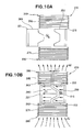
FIG. 12 , the prior art heating means 400 comprises: an induction heating device composed of an upper-side high-frequency induction coil 401 of a conductor wire of spiral form wound clockwise from the center to the outside; a lower-side high-frequency induction coil 402 of a conductor wire of spiral form wound counterclockwise from the center to the outside and connected to the center of the upper-side high-frequency induction coil 401; and a high-frequency power supply 405 connected to the upper-side high-frequency induction coil 401 via alead wire 403, and connected to the lower-side high-frequency induction coil 402 via alead wire 404. -
FIG. 13 hereof illustrates a method for using the aforedescribed high-frequency induction coils. A movingmold 407 is separated from astationary mold 406, and the upper-side high-frequency induction coil 401 and the lower-side high-frequency induction coil 402 are inserted between thecavity surface 408 of thestationary mold 406 and thecavity surface 409 of the movingmold 407. Prior to injecting molten resin into the cavity of the mold, thecavity surfaces -
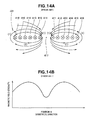
FIGS. 14A and 14B illustrate an operation of the above-described high-frequency induction coils. InFIG. 14A , the coils are illustrated using only the high-frequency induction coil 401. An electrical current is caused to flow through the high-frequency induction coil 401 by the high-frequency power supply 405 (FIG. 13 ), generating a magnetic field. Once the magnetic field is generated, lines of magnetic force are generated in the high-frequency induction coil 401 as indicated by the arrows (1). -
FIG. 14B depicts a relationship of position in the diametrical direction of the high-frequency induction coil 401 and an intensity of the magnetic field. The intensity of the magnetic field reaches maximum in proximity to a secondintermediate part 413 and a thirdintermediate part 414, and reaches minimum in acenter space part 417. In other words, the intensity of the magnetic field generated by the high-frequency induction coil 401 is not constant with respect to position in the direction of coil diameter. - When the
cavity surfaces FIG. 13 , at the cavity surfaces that correspond to the secondintermediate part 413 and the thirdintermediate part 414 of the high-frequency induction coil 401, the amount of generated eddy current is greater due to high intensity of the magnetic field. On the other hand, at the cavity surfaces that correspond to aninnermost part 411, anoutermost part 416, and thecenter space part 417 of the high-frequency induction coil 401, the amount of generated eddy current is smaller due to low intensity of the magnetic field. - Where the amount of generated eddy current differs, a differential arises in Joule heat. If molten resin is injected and molded in a cavity having a heat differential among regions, flaws such as warpage, deformation, and the like, are generated in the resin molded article. Accordingly, there is a need for a molding technique by which molding quality can be improved.
- In die casting or injection molding, a material is injected in a molten state into the cavity of a mold, and a molded article is obtained by cooling the material to a solid from the molten state. If the flowability of the material declines at the time that the material is injected in a molten state, the material will solidify before reaching the corners of the cavity. This gives rise to short fill of the material, leading to poorer quality of the molded article, necessitating measures to promote flowability of the material.
- In order to promote flowability of the material, molding apparatuses in which measures are implemented for this purpose are known, for example, in Japanese Domestic Republication
2007-535786 FIG. 15 depicts a basic configuration of this prior art molding apparatus. - In
FIG. 15 , themolding apparatus 500 is composed of anupper die 501; alower die 502; a high-frequency induction coil 505 disposed in proximity to anouter wall face 503 of theupper die 501 and anouter wall face 504 of thelower die 502 so as to encircle the outer perimeter of theupper die 501 and thelower die 502; and a high-frequency power supply connected to the high-frequency induction coil 505. -
FIG. 16 depicts the action of themolding apparatus 500 depicted inFIG. 15 . According toFIG. 16 , in a state with theupper die 501 separated from thelower die 502, a current is caused to flow into the high-frequency induction coil 505 by the high-frequency power supply, and a magnetic field is generated in the high-frequency induction coil 505. In one moment of the time a magnetic field is generated, an eddy current is generated in theupper die 501 in the manner of the arrow (1), while an eddy current is generated in thelower die 502 in the manner of the arrow (2). - Because the
upper die 501 and thelower die 502 have electrical resistance, Joule heat is generated by the eddy currents and electrical resistance, and theupper die 501 and thelower die 502 are heated by this heat. If theupper die 501 and thelower die 502 are heated before material is injected in a molten state into the cavity, the flowability of the material is increased, and molding defects can be eliminated. - The high-
frequency induction coil 505 is wound in proximity to theouter wall face 503 of theupper die 501 and theouter wall face 504 of thelower die 502. It is accordingly necessary to take measures so that the high-frequency induction coil 505 does not impede the movement of theupper die 501 when theupper die 501 is lifted further in order to open the die, making the system cumbersome to use. Accordingly, there is a desire for a molding technique whereby operability can be further improved. - It is an object of the present invention to provide a molding technique whereby molding quality can be improved.
- According a first aspect of the present invention, there is provided a molding apparatus which comprises: heating means having a high-frequency induction coil and a high-frequency power supply connected to the high-frequency induction coil; and a pair of molds adapted to be heated by the heating means, wherein the high-frequency induction coil is disposed between respective cavity faces of the molds separated from each other, in a substantially parallel direction with respect to the cavity faces of the molds, and is wound in a helical fashion in the substantially parallel direction.
- In this arrangement, the high-frequency induction coil is disposed between the cavity faces of the separated pair of molds in a substantially parallel direction with respect to the cavity faces of the molds, and is wound in a helical fashion in the substantially parallel direction. In other words, the high-frequency induction coil is disposed substantially parallel with respect to the cavity faces. When an electrical current is caused to flow to the high-frequency induction coil by the high-frequency power supply to generate a magnetic field, lines of magnetic force are generated so as to substantially conform to the cavity faces, and therefore eddy currents are generated uniformly with respect to the cavity faces. Because the molds have electrical resistance, Joule heat is generated by the eddy currents and electrical resistance, and the cavity faces can be heated by this heat. When a material in the molten state is injected into the cavity of the heated molds, flowability of the material is promoted, and therefore the quality of the molded article can be improved. Consequently, a molding apparatus whereby molding quality can be improved can be provided.
- Preferably, the high-frequency induction coil comprises a coil assembly of plural coils disposed in an array. In a case where the high-frequency induction coil is composed of a single coil, while an elongated cavity face of a small surface area can be heated, heating will take considerable time in the case of a cavity face with a large surface area. In this regard, because the high-frequency induction coil of the present invention has a plurality of coils disposed in an array, a cavity face with a large surface area can be heated in a short time.
- According to a second aspect of the present invention, there is provided a molding method implemented using a molding apparatus which comprises heating means having a high-frequency induction coil and a high-frequency power supply, and a die comprised of a stationary mold and a moveable mold, the method comprising the steps of: maintaining the moveable mold in a state separated from the stationary mold by a predetermined distance; inserting the high-frequency induction coil, which is wound in a helical fashion in a direction substantially parallel with respect to a cavity face of the stationary mold and a cavity face of the moveable mold, in the substantially parallel direction between the cavity face of the stationary mold and the cavity face of the moveable mold; heating the stationary mold and the moveable mold by Joule heat obtained by causing an electrical current to flow from the high-frequency power supply to the high-frequency induction coil to thereby generate a magnetic field and an eddy current in the stationary mold and the moveable mold; closing the die by bringing together the moveable mold and the stationary mold when the stationary mold and the moveable mold are heated to a predetermined temperature; injecting a molten-state material into a cavity of the closed stationary mold and moveable mold; and opening the die by separating the moveable mold from the stationary mold in order to retrieve a molded article having cooled to a solid in the cavity.
- In the coil insertion step according to the second aspect of the present invention, the high-frequency induction coil wound in a helical fashion in a substantially parallel direction with respect to the cavity face of the stationary mold and the cavity face of the moveable mold is inserted in the substantially parallel direction between the cavity face of the stationary mold and the cavity face of the moveable mold. In other words, the high-frequency induction coil is disposed substantially parallel with respect to the cavity faces.
- When an electrical current is caused to flow to the high-frequency induction coil by the high-frequency power supply to generate a magnetic field, lines of magnetic force are generated so as to substantially conform to the cavity faces, and therefore eddy currents are generated uniformly with respect to the cavity faces. Because the molds have electrical resistance, Joule heat is generated by the eddy currents and electrical resistance, and the cavity faces can be heated by this heat. When a material in the molten state is injected into the heated mold cavity, flowability of the material is promoted, and therefore the quality of the molded article can be improved. Consequently, a molding method whereby molding quality can be improved can be provided.
- Desirably, the high-frequency induction coil comprises a plurality of coils disposed in an array. Consequently, in a case where the high-frequency induction coil is composed of a single coil, an elongated cavity face of a small surface area can be heated, whereas heating will take considerable time in the case of a cavity face with a large surface area. In this regard, because the high-frequency induction coil of the present invention has a plurality of coils disposed in an array, a cavity face with a large surface area can be heated in a short time.
- According to a third aspect of the present invention, there is provided a molding apparatus for obtaining a molded article using a pair of molds heated by heating means, wherein the heating means comprises: a pair of high-frequency induction coils respectively furnished in proximity to first outside faces of the pair of molds and to other outside faces of the pair of molds, which faces are parallel to the opening/closing direction of the pair of molds, ring sections wound a plurality of times in an annular configuration facing one another; and a high-frequency power supply connected to the pair of high-frequency induction coils, the high-frequency power supply adapted for imparting an electrical current to the high-frequency induction coils.
- In other words, the pair of high-frequency induction coils are disposed parallel to the opening/closing direction of the pair of molds, and accordingly there is no concern that the moveable mold will strike the high-frequency induction coils during die opening. Consequently, in a molding apparatus for heating molds by heating means, a device whereby operability can be further improved can be provided.
- According to a fourth aspect of the present invention, there is provided a molding method implemented using a molding apparatus which comprises heating means having a pair of high-frequency induction coils and a high-frequency power supply, and a die comprised of a stationary mold and a moveable mold, the method comprising the steps of: maintaining the moveable mold in a state separated a predetermined distanced from the stationary mold; disposing the coils such that the pair of high-frequency induction coils are brought into proximity with a first outside face of the stationary mold and a first outside face of the moveable mold, and with another outside face of the stationary mold and another outside face of the moveable mold, which faces are parallel to the moveable direction of the moveable mold, and the pair of high-frequency induction coils are disposed so that ring sections wound a plurality of times in an annular configuration within the high-frequency induction coils face one another; heating the stationary mold and the moveable mold by Joule heat obtained by causing an electrical current to flow from the high-frequency power supply to the pair of high-frequency induction coils to thereby generate a magnetic field and an Eddy current in the stationary mold and the moveable mold; closing the die by bringing together the moveable mold and the stationary mold when the stationary mold and the moveable mold are heated to a predetermined temperature; injecting a molten-state material into a cavity of the closed stationary mold and the moveable mold; and opening the die by separating the moveable mold from the stationary mold in order to retrieve the molded article cooled to a solid in the cavity.
- In the coil-disposing step, the pair of high-frequency induction coils are brought into proximity with a first outside face of the stationary mold and a first outside face of the moveable mold, and with another outside face of the stationary mold and another outside face of the moveable mold, which faces are parallel to the moveable direction of the moveable mold, and the pair of high-frequency induction coils are disposed with ring sections wound a plurality of times in an annular configuration within the high-frequency induction coils facing one another.
- In other words, the pair of high-frequency induction coils are disposed parallel to the mold opening/closing direction, and accordingly there is no concern that the moveable mold will strike the high-frequency induction coils during die opening. Consequently, in a molding method for heating molds by heating means, a method whereby operability can be further improved can be provided.
- Certain preferred embodiments of the present invention are described in detail below, by way of example only, with reference to the accompanying drawings, in which:
-
FIG. 1 is top plan view schematically illustrating a molding apparatus according to a first embodiment of the present invention; -
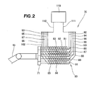
FIG. 2 is a view as seen in the direction ofarrow 2 ofFIG. 1 ; -
FIG. 3 is a view as seen in the direction ofarrow 3 ofFIG. 1 ; -
FIG. 4A and FIG. 4B are views illustrating a manner of insertion of a high-frequency induction coil between a stationary mold and a moveable mold; -
FIG. 5A, FIG. 5B, and FIG. 5C are views illustrating states leading up to heating of a cavity face of the moveable mold,FIG. 5B being a sectional view taken alongline 5B-5B ofFIG. 5A ; -
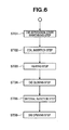
FIG. 6 is a flow diagram illustrating a molding method according to the first embodiment; -
FIG. 7 is a front elevational view illustrating a molding apparatus according to a second embodiment of the present invention; -
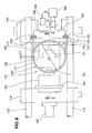
FIG. 8 is an enlarged view illustrating anarea 8 ofFIG. 7 ; -
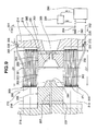
FIG. 9 is a sectional view taken along line 9-9 ofFIG. 8 ; -
FIG. 10A to FIG. 10D are views illustrating states leading up to heating of a stationary mold and a moveable mold and die opening,FIG. 10D being a sectional view alongline 10D-10D ofFIG. 10C ; -
FIG. 11 is a flow diagram illustrating a molding method according to the second embodiment; -
FIG. 12 is a view illustrating a basic arrangement of a first prior-art molding apparatus; -
FIG. 13 is a view illustrating a method of use of a prior art high-frequency induction coil ofFIG. 12 ; -
FIG. 14A and FIG. 14B are views illustrating an operation of the prior art high-frequency induction coil ofFIG. 12 ; -
FIG. 15 is a view illustrating a basic arrangement of a second prior-art molding apparatus; and -
FIG. 16 is a view showing flow of lines of magnetic force in the molding apparatus ofFIG. 15 . - As depicted in
FIG. 1 , aninjection molding machine 10 according to a first embodiment is composed of adie closure device 12 disposed in the front part of abed 11, and aninjection device 31 disposed in the back part of thebed 11, so as to face toward thisdie closure device 12. A pair of molds provided to thedie closure device 12 is composed of astationary mold 50 and amoveable mold 60. - The
die closure device 12 is provided with astationary platen 13 attached to the center part of thebed 11; thestationary mold 50 which is attached to the front end of thisstationary platen 13 via a stationary-side attachment plate 14; asupport member 15 attached to the front end of thebed 11; fourtie bars 16 attached to thestationary platen 13 and to thesupport member 15; amoveable platen 17 attached in horizontal sliding fashion to the tie bars 16; themoveable mold 60 which is attached to the back end of thismoveable platen 17 via a moveable-side attachment plate 18; and adie closure cylinder 19 attached to thesupport member 15, for moving themoveable platen 17 and themoveable mold 60 in the horizontal direction. - The
injection device 31 is composed of aninjection cylinder 33 furnished on a slide mechanism 32 which is attached to the back part of thebed 11; aheated cylinder 34 attached to the front end of thisinjection cylinder 33 and having an internal screw; anozzle 35 attached to the front end of thisheated cylinder 34 and contacting a material injection port 56 (seeFIG. 3 ) of thestationary mold 50; ahopper 36 attached onto the back end of theheated cylinder 34, the hopper adapted for accommodating a resin material supplied into theheated cylinder 34; ascrew drive motor 37 attached to the back end of theinjection cylinder 33, the screw drive motor adapted for causing the screw to rotate; ascrew movement mechanism 38 disposed in the back part of theinjection cylinder 33, the screw movement mechanism adapted for causing the screw to move in the horizontal direction; and an injectiondevice movement cylinder 42 that links asupport member 39 attached to thestationary platen 13 to a slider 41 of the slide mechanism 32. - Through a pulling operation of the injection
device movement cylinder 42, the slider 41 moves alongrails die closure device 12, and therefore thenozzle 35 can be brought into contact with the material injection port of thestationary mold 50. - A
control device 44 controls the respective operations of thedie closure cylinder 19, thescrew drive motor 37, thescrew movement mechanism 38, and the injectiondevice movement cylinder 42. - Furthermore, heating means 70 is attached to the distal end of a
robot arm 45, and this heating means 70 is disposed facing into a space between thestationary mold 50 and themoveable mold 60. The construction of the heating means 70 is illustrated inFIG. 2 . - As depicted in
FIG. 2 , the heating means 70 is comprised of a high-frequency induction coil 80 attached to acoil support member 71, which is furnished to the distal end of therobot arm 45; and a high-frequency power supply 110 connected to this high-frequency induction coil 80. In other words, the heating means 70 is an induction heating device. - The high-
frequency induction coil 80 is a coil assembly of five coils disposed in an array. The five coils, lined up from top to bottom, are afirst coil 81, asecond coil 82, athird coil 83, afourth coil 84, and afifth coil 85. Thefirst coil 81 is wound in a helical fashion in a substantially parallel direction to the cavity faces (discussed later) of the stationary mold 50 (FIG. 1 ) and the moveable mold 60 (FIG. 1 ), onto afirst iron core 86 which is attached to thecoil support member 71. - Likewise, the
second coil 82 is wound in a helical fashion in a substantially parallel direction to the mold cavity faces, onto asecond iron core 87. Thethird coil 83 is wound onto athird iron core 88 in a helical fashion in a substantially parallel direction to the mold cavity faces. Thefourth coil 84 is wound onto afourth iron core 89 in a helical fashion in a substantially parallel direction to the mold cavity faces. Thefifth coil 85 is wound onto a fifth iron core in a helical fashion in a substantially parallel direction to the mold cavity faces, 91. Because thecoils - A
distal end 92 and aback end 93 of thefirst coil 81, adistal end 94 and aback end 95 of thesecond coil 82, adistal end 96 and aback end 97 of thethird coil 83, adistal end 98 and aback end 99 of thefourth coil 84, and adistal end 101 and aback end 102 of thefifth coil 85 are all connected to the high-frequency power supply 110. - In a state of the high-
frequency induction coil 80 being inserted between the cavity face of the stationary mold 50 (FIG. 1 ) and the cavity face of the moveable mold 60 (FIG. 1 ), an electrical current is caused to flow by the high-frequency power supply 110 to thefirst coil 81, thesecond coil 82, thethird coil 83, thefourth coil 84, and thefifth coil 85 of the high-frequency induction coil 80. When the electrical current flows to therespective coils - The high-
frequency induction coil 80 is a coil assembly of fivecoils frequency induction coil 80 of the present invention has fivecoils - While the present embodiment has depicted an example in which the high-
frequency induction coil 80 is composed of five coils, the quantity of coils may be determined as otherwise desired, and may be four or fewer, or five or more. It is permissible to modify the coil length according to the size of the molds. Next, the construction of the high-frequency induction coil 80 is described based onFIG. 3 . - As depicted in
FIG. 3 , in the high-frequency induction coil 80, thefirst coil 81 is disposed substantially parallel to an upper-side mating face 51 of thestationary mold 50 and an upper-side mating face 61 of themoveable mold 60. - The
second coil 82 is disposed substantially parallel to an upper-side cavity face 52 of thestationary mold 50 and an upper-side cavity face 62 of themoveable mold 60. Thethird coil 83 is disposed substantially parallel to an intermediate cavity face 53 of thestationary mold 50 and an intermediate cavity face 63 of themoveable mold 60. Thefourth coil 84 is disposed substantially parallel to a lower-side cavity face 54 of thestationary mold 50 and a lower-side cavity face 64 of themoveable mold 60. Thefifth coil 85 is disposed substantially parallel to a lower-side mating face 55 of thestationary mold 50 and a lower-side mating face 65 of themoveable mold 60. - The action of the
injection molding machine 10 discussed above is discussed next. - As depicted in
FIG. 4A ., the high-frequency induction coil 80 faces a space between thestationary mold 50 and themoveable mold 60. The high-frequency induction coil 80 is moved as shown by an arrow (2) by therobot arm 45. - As depicted in
FIG. 4B , the high-frequency induction coil 80 is positioned in the space between thestationary mold 50 and themoveable mold 60. Next, heating of thestationary mold 50 and themoveable mold 60 is described withFIG. 5 . - As depicted in
FIG. 5A , thefirst coil 81 is disposed substantially parallel to the upper-side mating faces 51, 61, between the separatedstationary mold 50 andmoveable mold 60. Thesecond coil 82 is disposed substantially parallel to the upper-side cavity faces 52, 62, between the separatedstationary mold 50 andmoveable mold 60. Thethird coil 83 is disposed substantially parallel to the intermediate cavity faces 53, 63, between the separatedstationary mold 50 andmoveable mold 60. Thefourth coil 84 is disposed substantially parallel to the lower-side cavity faces 54, 64, between the separatedstationary mold 50 andmoveable mold 60. Thefifth coil 85 is disposed substantially parallel to the lower-side mating faces 55, 65, between the separatedstationary mold 50 andmoveable mold 60. - As depicted in
FIG. 5B , a magnetic field is generated when an electrical current is caused to flow by the high-frequency power supply 110 (FIG. 2 ) to thethird coil 83 of the high-frequency induction coil 80 as shown by arrows (3). Through generation of this magnetic field, lines of magnetic force are generated so as to substantially conform to the intermediate cavity face 53 of thestationary mold 50 and the intermediate cavity face 63 of themoveable mold 60, as shown by arrows (4). -
FIG. 5C depicts a relationship of magnetic field strength and position in the lengthwise direction of thethird coil 83. The magnetic field strength is constant with respect to the position in the coil lengthwise direction. - In
FIG. 5B , thethird coil 83 of the high-frequency induction coil 80 is disposed between the separatedstationary mold 50 andmoveable mold 60, in a substantially parallel direction with respect to the intermediate cavity face 53 of thestationary mold 50 and the intermediate cavity face 63 of themoveable mold 60, and is wound in a helical fashion in the substantially parallel direction. In other words, thethird coil 83 of the high-frequency induction coil 80 is disposed substantially parallel to the cavity faces 53, 63. - An electrical current is caused to flow to the
third coil 83 of the high-frequency induction coil 80 by the high-frequency power supply, and a magnetic field is generated. Through generation of the magnetic field, lines of magnetic force are generated so as to substantially conform to the cavity faces 53, 63, and therefore the magnetic field strength is constant with respect to the coil lengthwise direction. As long as the magnetic field strength is constant, eddy currents can be generated uniformly at the cavity faces 53, 63. - Because the molds have electrical resistance, Joule heat is generated by the eddy currents and electrical resistance, and the cavity faces can be heated by this heat. When a material in the molten state is injected into the heated mold cavity, flowability of the material is promoted, and therefore the quality of the molded article can be improved. Consequently, an injection molding machine 10 (
FIG. 1 ) whereby molding quality can be improved can be provided. - In the present embodiment, heating of the molds by the high-
frequency induction coil 80 was described using the example of the cavity faces 53, 63, but the cavity faces 52, 62, 54, 64 and the mating faces 51, 61, 55, and 65 are also heated simultaneously with the heating of the cavity faces 53, 63. Next, an injection molding method implemented using theinjection molding machine 10 is described. - As depicted in
FIG. 6 , in Step 01 ("step" is hereinafter denoted as "ST"), the moveable mold is maintained in a state distanced by a predetermined dimension from the stationary mold. Specifically, as depicted inFIG. 5A , the movement of themoveable mold 60 comes to a stop in a state distanced by a predetermined dimension L1 from thestationary mold 50. - In ST02, the high-frequency induction coil, which is wound in a helical fashion in a substantially parallel direction with respect to the cavity face of the stationary mold and the cavity face of the moveable mold, is inserted in a substantially parallel direction between the cavity face of the stationary mold and the cavity face of the moveable mold. Specifically, as depicted in
FIG. 4A , the high-frequency induction coil 80 faces the space between thestationary mold 50 and themoveable mold 60. The high-frequency induction coil 80 is moved by therobot arm 45 in a manner shown by arrow (2). - In ST03, an electrical current is caused to flow to the high-frequency induction coil by the high-frequency power supply, generating a magnetic field in the stationary mold and the moveable mold and generating eddy currents in the stationary mold and the moveable mold, whereupon the stationary mold and the moveable mold are heated by Joule heat obtained thereby.
- Specifically, as depicted in
FIG. 5B , when an electrical current is caused to flow to thethird coil 83 of the high-frequency induction coil 80 by the high-frequency power supply as shown by arrows (3), a magnetic field is generated. Through generation of this magnetic field, lines of magnetic force are generated so as to substantially conform to the cavity faces 53, 63 as shown by arrows (4). The magnetic field strength is constant with respect to the position in the coil lengthwise direction as depicted inFIG. 5C . If the magnetic field strength is constant, eddy currents can be generated uniformly at the cavity faces 53, 63. Because the molds have electrical resistance, Joule heat is generated by the eddy currents and electrical resistance, and the cavity faces can be heated by this heat. - In ST04, when the stationary mold and the moveable mold temperatures have reached a predetermined temperature, the moveable mold is joined up with the stationary mold to effect die closure. Specifically, in
FIG. 1 , when thestationary mold 50 and themoveable mold 60 temperatures have reached a predetermined temperature, thedie closure cylinder 19 is operated. Through the pushing operation of thedie closure cylinder 19, themoveable mold 60 is joined up with thestationary mold 50 to implement die closure. - In ST05, a material in a molten state is injected into the cavity of the die-closed stationary mold and moveable mold. Specifically, in
FIG. 1 , once themoveable mold 60 has been closed onto thestationary mold 50, a material in a molten state is injected into the cavity from the material injection port of thestationary mold 50. - In ST06, in order to retrieve the molded article which has cooled to a solid in the cavity, the moveable mold is separated from the stationary mold. Specifically, in
FIG. 1 , themoveable mold 60 is distanced from thestationary mold 50. Because the resin molded article is left adhering to the cavity face of themoveable mold 60, the resin molded article is ejected with an ejector pin. - In
FIG. 1 , the injection molding method is implemented by an injection molding machine provided with heating means 70 composed of the high-frequency induction coil 80 and the high-frequency power supply 110, and provided with thestationary mold 50 and themoveable mold 60. Molded articles are obtained using thestationary mold 50 and themoveable mold 60 heated by the heating means 70. - In
FIG. 6 , the injection molding method is composed of a die-separation-state-maintaining step (ST01), a coil insertion step (ST02), a heating step (ST03), a die-closing step (ST04), a material-injection step (ST05), and a die-opening step (ST06). - In the coil insertion step, as depicted in
FIG. 4A , thecoils frequency induction coil 80, which is wound in a helical fashion in a substantially parallel direction with respect to thecavity face 53 of thestationary mold 50 and thecavity face 63 of themoveable mold 60, is inserted in a substantially parallel direction between thecavity face 53 and thecavity face 63. In other words, the high-frequency induction coil 80 is disposed substantially parallel with respect to the cavity faces 53, 63. - As depicted in
FIG. 5B , when an electrical current is caused to flow by the high-frequency power supply 110 (FIG. 2 ) to thethird coil 83 of the high-frequency induction coil 80 as shown by arrows (3), a magnetic field is generated. Through generation of this magnetic field, lines of magnetic force are generated so as to substantially conform to the intermediate cavity face 53 of thestationary mold 50 and the intermediate cavity face 63 of themoveable mold 60, as shown by arrows (4). The magnetic field strength is constant with respect to position in the coil lengthwise direction, as depicted byFIG. 5C . - In
FIG. 5B , thethird coil 83 of the high-frequency induction coil 80 is disposed between the separatedstationary mold 50 andmoveable mold 60, in a substantially parallel direction with respect to the intermediate cavity face 53 of thestationary mold 50 and the intermediate cavity face 63 of themoveable mold 60, and is wound in a helical fashion in the substantially parallel direction. In other words, thethird coil 83 of the high-frequency induction coil 80 is disposed substantially parallel to the cavity faces 53, 63. - An electrical current is caused to flow to the
third coil 83 of the high-frequency induction coil 80 by the high-frequency power supply, and a magnetic field is generated. Through generation of the magnetic field, lines of magnetic force are generated so as to substantially conform to the cavity faces 53, 63, and therefore the magnetic field strength is constant with respect to position in the coil lengthwise direction. If the magnetic field strength is constant, eddy currents can be generated uniformly at the cavity faces 53, 63. - Because the molds have electrical resistance, Joule heat is generated by the eddy currents and electrical resistance, and the cavity faces can be heated by this heat. When a material in the molten state is injected into the heated mold cavity, flowability of the material is promoted, and therefore the quality of the molded article can be improved. Consequently, an injection molding method whereby molding quality can be improved can be provided.
- As depicted in
FIG. 2 , the high-frequency induction coil 80 has fivecoils frequency induction coil 80 of the present invention has fivecoils - As depicted in
FIG. 7 , aninjection molding machine 200 according to a second embodiment includes adie closure device 212 disposed in the front part of abed 211, and aninjection device 231 disposed in the rear part of thebed 211 so as to face toward thisdie closure device 212. A pair of molds provided to thedie closure device 12 is composed of astationary mold 250 and amoveable mold 260. - The
die closure device 212 is provided with astationary platen 214 attached to acenter support stage 213 rising from the center part of thebed 211; thestationary mold 250 attached to the front end of thisstationary platen 214 via a stationary-side attachment plate 215; asupport member 217 attached to a frontend support stage 216 rising from the front end of thebed 211; fourtie bars 218 attached to thestationary platen 214 and to thesupport member 217; amoveable platen 219 attached in horizontal sliding fashion to the tie bars 218; themoveable mold 260 which is attached to the back end of thismoveable platen 219 via a moveable-side attachment plate 221; anejection cylinder 222 attached to the front end of themoveable platen 219, for thrusting out an ejection pin; and adie closure cylinder 223 linking thecenter support stage 213 and themoveable platen 219. - An
automated retrieval robot 224 capable of movement in three-dimensional directions is attached to the upper end of thestationary platen 214. Theautomated retrieval robot 224 retrieves the resin molded article ejected from themoveable mold 260. - The
injection device 231 is comprised of aninjection cylinder 233 furnished on aslide mechanism 232 which is attached to the back part of thebed 211; aheated cylinder 234 attached to the front end of thisinjection cylinder 233 and having an internal screw; anozzle 235 attached to the front end of thisheated cylinder 234 and contacting a material injection port of thestationary mold 250; ahopper 236 attached onto the back end of theheated cylinder 234, the hopper adapted for accommodating a resin material supplied into theheated cylinder 234; ascrew drive motor 237 attached to the back end of theinjection cylinder 233, the screw drive motor adapted for causing the screw to rotate; ascrew movement mechanism 238 disposed in the back part of theinjection cylinder 233, the screw movement mechanism adapted for causing the screw to move in the horizontal direction; and an injectiondevice movement cylinder 242 that links thecenter support stage 213 to aslider 241 of theslide mechanism 232. - Through a pulling operation of the injection
device movement cylinder 242, theslider 241 moves along arail 243 toward thedie closure device 212 side, and therefore thenozzle 235 can be brought into contact with the material injection port of thestationary mold 250. - A
control device 244 controls the respective operations of theejection cylinder 222, thedie closure cylinder 223, theautomated retrieval robot 224, thescrew drive motor 237, thescrew movement mechanism 238, and the injectiondevice movement cylinder 242. - Heating means 270 for heating the
stationary mold 250 and themoveable mold 260 is furnished to the left side of thestationary platen 214 and thestationary mold 250. - As depicted in
FIG. 8 , the heating means 270 is provided with a left high-frequency induction coil 280 attached via a left heat-insulator 72 to aleft side face 225 of thestationary platen 214, and having aleft ring section 271 wound a plurality of times in an annular configuration; and a high-frequency power supply 290 connected via a left lower-side pipeline 282 to a lower-side terminus 281 of this left high-frequency induction coil 280, and connected via a left upper-side pipeline 284 to an upper-side terminus 283 of the left high-frequency induction coil 280, to impart an electrical current to the left high-frequency induction coil 280. The high-frequency power supply 290 has a jacket construction, and is connected to the lower-side and upper-side pipelines chiller unit 291 is connected to the left lower-side pipeline 281 and to the high-frequency power supply 290. The left high-frequency induction coil 280 is connected to the high-frequency power supply 290 by wiring, not illustrated. A water-cooled bus par can be cited as an analogous product to this high-frequency power supply 290. This water-cooled bus par is designed so that water passes through the inside of a pipe, and an electrical current flows through the wall of the pipe. - A coolant constantly flows inside the left high-
frequency induction coil 280, and the left high-frequency induction coil 280 is cooled by this coolant. The coolant returned to the high-frequency power supply 290 from the left high-frequency induction coil 280 is at an elevated temperature, and is therefore cooled by a refrigerant inside thechiller unit 291, then again caused to flow to the inside of the left high-frequency induction coil 280. In other words, the coolant circulates through the left high-frequency induction coil 280, the high-frequency power supply 290, and thechiller unit 291. - Additionally, the left high-
frequency induction coil 280 is formed such that thestationary mold 250, and themoveable mold 260 having moved to a position depicted by imaginary lines due to the pulling operation of the die-closure cylinder 223 (FIG. 7 ), fit inside an inside diameter D1. Where the dimension between thestationary mold 250 and themoveable mold 260 depicted by the imaginary lines is designated as L1, this dimension L1 depicts a predetermined dimension established prior to heating thestationary mold 250 and themoveable mold 260. A stationary-side cavity face 251 of concave shape is furnished to thestationary mold 250, and a moveable-side cavity face 261 of convex shape is furnished to themoveable mold 260. - In addition to the left high-
frequency induction coil 280, the heating means 270 is provided with a right high-frequency induction coil formed with dimensions identical to the left high-frequency induction coil 280 and disposed coaxially therewith. The construction of the heating means 270 is next described in detail with reference toFIG. 9 . - As depicted in
FIG. 9 , the heating means 270 is comprised of the left high-frequency induction coil 280 that, with thestationary mold 250 and themoveable mold 260 depicted by the imaginary lines in a state distanced by the predetermined dimension L1 (FIG. 8 ), is furnished in proximity to a stationary mold left outsideface 252 of thestationary mold 250 and a moveable mold left outsideface 262 of themoveable mold 260, and has aleft ring section 271 wound seven times in an annular configuration; a right high-frequency induction coil 300 furnished in proximity to a stationary mold right outsideface 253 of thestationary mold 250 and a moveable mold right outsideface 263 of themoveable mold 260, and having aright ring section 292 wound seven times in an annular configuration; and the high-frequency power supply 290 which is connected to the left high-frequency induction coil 280 and the right high-frequency induction coil 300, and which imparts an electrical current to the left high-frequency induction coil 280 and the right high-frequency induction coil 300. In other words, the heating means 270 is an induction heating device. - In the second embodiment, the number of times the
left ring section 271 and theright ring section 292 are wound is seven, but the number may be determined as desired. A greater number of windings corresponds to a stronger magnetic force; therefore, preferably the number of windings is increased. - The stationary mold left outside
face 252, the moveable mold left outsideface 262, the stationary mold right outsideface 253, and the moveable mold right outsideface 263 are faces that respectively lie parallel to the opening/closing direction of thestationary mold 250 and themoveable mold 260. The right high-frequency induction coil 300 is attached via aright heat insulator 295 to aright side face 226 of thestationary platen 214. - The left high-
frequency induction coil 280 and the right high-frequency induction coil 300 are a pair of high-frequency induction coils whoseleft ring section 271 andright ring section 292 face toward one another. The left high-frequency induction coil 280 and the right high-frequency induction coil 300 are formed so as to have the same inside diameter D1 and disposed on anidentical axis 301. - The high-
frequency power supply 290 is connected via a right lower-side pipeline 303 to a lower-side terminus 302 of the right high-frequency induction coil 300, and is connected via a right upper-side pipeline 305 to an upper-side terminus 304 of the right high-frequency induction coil 300. Coolant circulates through the right high-frequency induction coil 300, the high-frequency power supply 290, and thechiller unit 291, and coolant returned to the high-frequency power supply 290 is cooled by thechiller unit 291. - Next, the action of the
injection molding machine 10 discussed above is described based onFIG. 10A to FIG. 10D . - As depicted in
FIG. 10A , theleft ring section 271 of the left high-frequency induction coil 280 and theright ring section 292 of the right high-frequency induction coil 300 face toward one another, with thestationary mold 250 disposed between theleft ring section 271 and theright ring section 292. Themoveable mold 260 is moved toward thestationary mold 250 in the manner shown by arrow (3). - As depicted in
FIG. 10B , movement of themoveable mold 260 comes to a stop in a state distanced by the predetermined dimension L1 from thestationary mold 50. An electrical current is caused to flow to the left high-frequency induction coil 280 and the right high-frequency induction coil 300 by the high-frequency power supply 290 (FIG. 9 ), and taken at a given moment, a magnetic field is generated as shown by arrows (4), (5). Through generation of this magnetic field, eddy currents are generated in thestationary mold 250 as shown by arrows (6), and eddy currents are generated in themoveable mold 260 as shown by arrows (7). - Because the
stationary mold 250 and themoveable mold 260 have electrical resistance, Joule heat is generated by the eddy currents and electrical resistance, and thestationary mold 250 and themoveable mold 260 are heated by this heat. Heating of thestationary mold 250 and themoveable mold 260 is implemented immediately prior to die closure. - Next, the actions of molding a resin molded article and die opening are described.
- As depicted in
FIG. 10C , themoveable mold 260 is distanced from thestationary mold 250, leaving a resin moldedarticle 306 adhering to the moveable-side cavity face 261 of themoveable mold 260. In other words, this is the mold opening state. - As depicted in
FIG. 10D , because the left high-frequency induction coil 280 and the right high-frequency induction coil 300 are disposed to the left and right of themoveable mold 260, there are no obstacles above themoveable mold 260. Because of this, after the resin moldedarticle 306 is ejected from themoveable mold 260 by an ejection pin 307 (FIG. 10C ), the resin moldedarticle 306 can be retrieved smoothly from above by the automated retrieval robot 224 (FIG. 8 ). - As depicted in
FIG. 10B , with themoveable mold 260 in a state distanced by the predetermined dimension L1 from thestationary mold 250, the left high-frequency induction coil 280 is furnished in proximity to the moveable mold left outsideface 262 of themoveable mold 260 and the stationary mold left outsideface 252 of thestationary mold 250. With themoveable mold 260 in a state distanced by the predetermined dimension L1 from thestationary mold 250, the right high-frequency induction coil 300 is furnished in proximity to the moveable mold right outsideface 263 of themoveable mold 260 and the stationary mold right outsideface 253 of thestationary mold 250. - In other words, because the left high-
frequency induction coil 280 and the right high-frequency induction coil 300 are disposed parallel to the opening/closing direction of thestationary mold 250 and themoveable mold 260, there is no concern that themoveable mold 260 will strike the high-frequency induction coils 280, 300 during die opening. Consequently, in the injection molding machine 200 (FIG. 8 ) in which thestationary mold 250 and themoveable mold 260 are heated by the heating means 270, a device enabling improved operability can be provided. - Next, an injection molding method implemented using the
injection molding machine 10 is described. - As depicted in
FIG. 11 , in Step 01 ("step" is hereinafter denoted as "ST"), the moveable mold is maintained in a state distanced by a predetermined dimension from the stationary mold. Specifically, as depicted inFIG. 10B , movement of themoveable mold 260 comes to a stop in a state distanced by a predetermined dimension L1 from thestationary mold 250. - In ST02, the pair of high-frequency induction coils is brought into proximity to a first outside face of the stationary mold and a first outside face of the moveable mold, and to another outside face of the stationary mold and another outside face of the moveable mold, which faces are parallel to the moveable direction of the moveable mold. The pair of high-frequency induction coils is disposed so that the ring sections wound a plurality of times in an annular configuration face one another.
- Specifically, as depicted in
FIG. 10B , the left high-frequency induction coil 280 is brought into proximity to the moveable mold left outsideface 262 of themoveable mold 260 and stationary mold left outsideface 252 of thestationary mold 250. The right high-frequency induction coil 300 is brought into proximity to the moveable mold right outsideface 263 of themoveable mold 260 and stationary mold right outsideface 253 of thestationary mold 250. Further, the left high-frequency induction coil 280 and the right high-frequency induction coil 300 are disposed so that theleft ring section 271 and theright ring section 292 wound seven times in an annular configuration face one another. As depicted inFIG. 9 , the left high-frequency induction coil 280 and the right high-frequency induction coil 300 are formed so as to have the same inside diameter D1 and are disposed on anidentical axis 301. - In ST03, an electrical current is caused to flow to the pair of high-frequency induction coils by the high-frequency power supply, generating a magnetic field in the stationary mold and the moveable mold and generating eddy currents in the stationary mold and the moveable mold, with the stationary mold and the moveable mold being heated by Joule heat obtained thereby.
- Specifically, as depicted in
FIG. 10B , when an electrical current is caused to flow to the left high-frequency induction coil 280 and the right high-frequency induction coil 300 by the high-frequency power supply, a magnetic field is generated as shown by arrows (4), (5). Through generation of this magnetic field, eddy currents are generated in thestationary mold 250 as shown by arrows (6), and eddy currents are generated in themoveable mold 260 as shown by arrows (7). Because thestationary mold 250 and themoveable mold 260 have electrical resistance, Joule heat is generated by the eddy currents and electrical resistance, and thestationary mold 250 and themoveable mold 260 are heated by this heat. - In ST04, when the stationary mold and the moveable mold temperatures have reached a predetermined temperature, the moveable mold is joined up with the stationary mold to effect die closure. Specifically, in
FIG. 7 , when thestationary mold 250 and themoveable mold 260 temperatures have reached a predetermined temperature, thedie closure cylinder 223 is caused to carry out a pulling operation. Apiston rod 308 of thedie closure cylinder 223 advances, and therefore themoveable mold 260 is joined up with thestationary mold 250 to implement die closure. - In ST05, a material in a molten state is injected into the cavity of the die-closed stationary mold and moveable mold. Specifically, in
FIG. 9 , after themoveable mold 260 has closed onto thestationary mold 250, a material in a molten state is injected into the cavity from thematerial injection port 309 of thestationary mold 250. - In ST06, in order to retrieve the molded article which has cooled to a solid in the cavity, the moveable mold is separated from the stationary mold. Specifically, as depicted in
FIG. 10C , themoveable mold 260 is distanced from thestationary mold 250. Because the resin moldedarticle 306 is left adhering to the movable-side cavity face 261 of themoveable mold 260, the resin moldedarticle 306 is ejected with theejector pin 307. - In
FIG. 9 , the injection molding method is a method implemented by an injection molding machine provided with heating means 270 composed of the high-frequency power supply 290, the left high-frequency induction coil 280, and the right high-frequency induction coil 300, and provided with thestationary mold 250 and themoveable mold 260; and molded articles are obtained using thestationary mold 250 and themoveable mold 260 heated by the heating means 270. - In
FIG. 11 , the injection molding method is comprised of a die-separation-state-maintaining step (ST01), a coil-disposing step (ST02), a heating step (ST03), a die-closing step (ST04), a material-injection step (ST05), and a die-opening step (ST06). - In the coil-disposing step, as depicted in
FIG. 10B , the left high-frequency induction coil 280 is brought into proximity with the moveable mold left outsideface 262 and the stationary mold left outsideface 252 which are parallel to the movable direction of themoveable mold 260. The right high-frequency induction coil 300 is brought into proximity with the moveable mold right outsideface 263 and the stationary mold right outsideface 253 which are parallel to the movable direction of themoveable mold 260. Further, the left high-frequency induction coil 280 and the right high-frequency induction coil 300 are disposed with theleft ring section 271 and theright ring section 292 wound seven times in an annular configuration facing one another. - In other words, because the left high-
frequency induction coil 280 and the right high-frequency induction coil 300 are disposed parallel to the opening/closing direction of thestationary mold 250 and themoveable mold 260, there is no concern that themoveable mold 260 will strike the high-frequency induction coils 280, 300 during die opening. Consequently, in a molding method whereby thestationary mold 250 and themoveable mold 260 are heated by the heating means 270, it is possible to provide a method enabling improved operability. - In the embodiment, an example of application of the molding apparatus according to the present invention to an injection molding machine was depicted; however, application to a die casting device is also possible. Further, whereas in the embodiment, an example of application of the molding method according to the present invention to an injection molding method was described, application to a die casting method is possible as well.
- While the second embodiment depicted an example in which the pair of high-frequency induction coils is disposed to the left and right of the die closure device, the coils could be disposed above and below the die closure device instead.
- While the second embodiment depicted an example in which the attachment position of the high-frequency induction coils is the side face of the stationary platen, the side face of the movable platen, or the bed, would also be acceptable. The high-frequency induction coils may be attached to the distal end of a robot arm furnished separately from the molding apparatus.
- Further, whereas in the second embodiment the shape of the high-frequency induction coils according to the present invention is ring-shaped (
FIG. 8 ), an elliptical shape or square shape would also be acceptable. However, it is essential for the stationary mold and the moveable mold to be accommodated in the inside of the ellipse or the inside of the square. - The molding technique of the present invention is suitable for heating of molds used in injection molding techniques.
Claims (6)
- A molding apparatus comprising:heating means (70) having a high-frequency induction coil (80) and a high-frequency power supply (110) connected to the high-frequency induction coil; anda pair of molds (50, 60) adapted to be heated by the heating means (70),wherein the high-frequency induction coil (80) is disposed between respective cavity faces (53, 63) of the molds (50, 60) separated from each other, in a substantially parallel direction with respect to the cavity faces (53, 63) of the molds (50, 60), and is wound in a helical fashion in the substantially parallel direction.
- The molding apparatus of claim 1, wherein the high-frequency induction coil (80) comprises a coil assembly of plurality coils disposed in an array.
- A molding method implemented using a molding apparatus (10) which comprises heating means (70) having a high-frequency induction coil (80) and a high-frequency power supply (110), and a die comprised of a stationary mold (50) and a moveable mold (60), the method comprising the steps of:maintaining the moveable mold (60) in a state separated from the stationary mold (50) by a predetermined distance;inserting the high-frequency induction coil (80), which is wound in a helical fashion in a direction substantially parallel with respect to a cavity face (53) of the stationary mold (50) and a cavity face (63) of the moveable mold (60), in the substantially parallel direction between the cavity face (53) of the stationary mold and the cavity face (63) of the moveable mold;heating the stationary mold (50) and the moveable mold (60) by Joule heat obtained by causing an electrical current to flow from the high-frequency power supply (110) to the high-frequency induction coil (80) to thereby generate a magnetic field and an eddy current in the stationary mold (50) and the moveable mold (60);closing the die by bringing together the moveable mold (60) and the stationary mold (50) when the stationary mold (50) and the moveable mold (60) are heated to a predetermined temperature;injecting a molten-state material into a cavity (53, 63) of the closed stationary mold (50) and moveable mold (60); andopening the die by separating the moveable mold (60) from the stationary mold (50) in order to retrieve a molded article having cooled to a solid in the cavity (53, 63).
- The molding method according to any of the preceding claims, wherein the high-frequency induction coil (80) comprises a plurality of coils disposed in an array.
- A molding apparatus for obtaining a molded article (306) using a pair of molds (250, 260) heated by heating means (270),
wherein the heating means (270) comprises:a pair of high-frequency induction coils (280, 300) respectively furnished in proximity to first outside faces (252, 262) of the pair of molds and to other outside faces (253, 263) of the pair of molds, which faces are parallel to the opening/closing direction of the pair of molds (250, 260), ring sections (271, 292) wound a plurality of times in an annular configuration facing one another; anda high-frequency power supply (290) connected to the pair of high-frequency induction coils (280, 300), the high-frequency power supply adapted for imparting an electrical current to the high-frequency induction coils. - A molding method implemented using a molding apparatus (200) which comprises heating means (270) having a pair of high-frequency induction coils (280, 300) and a high-frequency power supply (290), and a die comprised of a stationary mold (250) and a moveable mold (260), the method comprising the steps of:maintaining the moveable mold (260) in a state separated a predetermined distanced from the stationary mold (250);disposing the coils such that the pair of high-frequency induction coils (280, 300) are brought into proximity with a first outside face (252) of the stationary mold (250) and a first outside face (262) of the moveable mold (260), and with another outside face (253) of the stationary mold and another outside face (263) of the moveable mold, which faces are parallel to the moveable direction of the moveable mold (260), and the pair of high-frequency induction coils (280, 300) are disposed so that ring sections (271, 292) wound a plurality of times in an annular configuration within the high-frequency induction coils face one another;heating the stationary mold and the moveable mold by Joule heat obtained by causing an electrical current to flow from the high-frequency power supply (290) to the pair of high-frequency induction coils (280, 300) to thereby generate a magnetic field and an Eddy current in the stationary mold (250) and the moveable mold (260);closing the die by bringing together the moveable mold and the stationary mold when the stationary mold (250) and the moveable mold (260) are heated to a predetermined temperature;injecting a molten-state material into a cavity of the closed stationary mold (250) and the moveable mold (260); andopening the die by separating the moveable mold (260) from the stationary mold (250) in order to retrieve the molded article (306) cooled to a solid in the cavity.
Applications Claiming Priority (2)
| Application Number | Priority Date | Filing Date | Title |
|---|---|---|---|
| JP2010210069A JP5271325B2 (en) | 2010-09-17 | 2010-09-17 | Molding apparatus and molding method |
| JP2010209988A JP2012061824A (en) | 2010-09-17 | 2010-09-17 | Molding device and molding method |
Publications (2)
| Publication Number | Publication Date |
|---|---|
| EP2431151A2 true EP2431151A2 (en) | 2012-03-21 |
| EP2431151A3 EP2431151A3 (en) | 2012-05-30 |
Family
ID=45034233
Family Applications (1)
| Application Number | Title | Priority Date | Filing Date |
|---|---|---|---|
| EP11181568A Withdrawn EP2431151A3 (en) | 2010-09-17 | 2011-09-16 | Molding apparatus and method |
Country Status (3)
| Country | Link |
|---|---|
| US (1) | US8808606B2 (en) |
| EP (1) | EP2431151A3 (en) |
| CN (1) | CN102407594B (en) |
Cited By (1)
| Publication number | Priority date | Publication date | Assignee | Title |
|---|---|---|---|---|
| WO2018005027A1 (en) * | 2016-06-30 | 2018-01-04 | iMFLUX Inc. | Injection molding with targeted heating of mold cavities in a non-molding position |
Families Citing this family (7)
| Publication number | Priority date | Publication date | Assignee | Title |
|---|---|---|---|---|
| JP5764408B2 (en) * | 2011-06-30 | 2015-08-19 | 株式会社ユーシン精機 | Mold take-out machine |
| US20140374959A1 (en) * | 2013-06-25 | 2014-12-25 | James PEPLINSKI | Injection molding method with infrared preheat |
| WO2017185189A1 (en) * | 2016-04-29 | 2017-11-02 | École De Technologie Supérieure | A low-pressure powder injection molding machine, kit and method |
| FR3051136A1 (en) * | 2016-05-10 | 2017-11-17 | Roctool | METHOD AND DEVICE FOR HEATING A MOLD |
| US11413802B2 (en) * | 2018-03-22 | 2022-08-16 | Honda Motor Co., Ltd. | Reusable mold for injection molding and molding method |
| US10981300B2 (en) * | 2018-12-12 | 2021-04-20 | The Boeing Company | Induction heating system for molding a thermoplastic article and method for molding a thermoplastic article |
| DE102022130109B3 (en) | 2022-11-15 | 2024-05-02 | Dr. Ing. H.C. F. Porsche Aktiengesellschaft | Method and device for producing an electrical machine with plastic seals on the front sides of the stator laminated core |
Citations (1)
| Publication number | Priority date | Publication date | Assignee | Title |
|---|---|---|---|---|
| JPH0890623A (en) | 1994-09-28 | 1996-04-09 | Asahi Eng Co Ltd | High frequency induction coil for mold heating and molding equipment |
Family Cites Families (26)
| Publication number | Priority date | Publication date | Assignee | Title |
|---|---|---|---|---|
| GB1425837A (en) * | 1973-05-09 | 1976-02-18 | Gkn Sankey Ltd | Plastic mouldings |
| US4340551A (en) * | 1980-08-11 | 1982-07-20 | Asahi-Dow Limited | Injection molded articles with improved surface characteristics, production of same and apparatus therefor |
| US4439492A (en) * | 1980-08-11 | 1984-03-27 | Asahi-Dow Limited | Injection molded articles with improved surface characteristics |
| US5062786A (en) * | 1988-12-12 | 1991-11-05 | Canon Kabushiki Kaisha | Molding device for molding optical elements |
| JPH02310013A (en) * | 1989-05-24 | 1990-12-25 | Sekisui Chem Co Ltd | High-frequency induction heating method and heating device |
| JPH03225A (en) * | 1989-05-29 | 1991-01-07 | Yokohama Rubber Co Ltd:The | Extrusion cross-head |
| JPH0318954U (en) * | 1989-06-30 | 1991-02-25 | ||
| JP3461033B2 (en) * | 1994-06-22 | 2003-10-27 | 扶桑産業株式会社 | Display shelf card attachment |
| US5851474A (en) * | 1995-04-11 | 1998-12-22 | Brunel University Of Uxbridge | Injection molding with periodic forces to the material in the mold |
| DE60013392T2 (en) * | 1999-05-12 | 2005-09-08 | Ju-Oh Inc., Hiratsuka | INDUCTION HEATING PROCESS FOR DISTRIBUTORS OF HOT CHANNEL METAL SHAPES AND COIL UNIT FOR INDUCTION HEATING |
| JP2001300999A (en) * | 2000-04-20 | 2001-10-30 | Canon Inc | Injection molded article molding method, apparatus and molded article |
| JP3839228B2 (en) * | 2000-07-31 | 2006-11-01 | 株式会社神戸製鋼所 | Raw tire preheating method and apparatus |
| JP4416159B2 (en) * | 2004-02-04 | 2010-02-17 | 株式会社十王 | Mold |
| KR100616750B1 (en) * | 2004-02-24 | 2006-08-28 | 주식회사 성우하이텍 | A warm hydro-forming device |
| FR2867939B1 (en) | 2004-03-18 | 2007-08-10 | Roctool | METHOD FOR HEATING MATERIALS TO PRODUCE OBJECTS AND DEVICE USING THE METHOD |
| JP2006008479A (en) * | 2004-06-29 | 2006-01-12 | Matsushita Electric Ind Co Ltd | Induction heating type molding equipment |
| JP4519586B2 (en) * | 2004-09-06 | 2010-08-04 | 株式会社リコー | Molding equipment |
| JP2007005055A (en) * | 2005-06-22 | 2007-01-11 | Fuji Electric Fa Components & Systems Co Ltd | Induction heating roller device |
| FR2890588B1 (en) * | 2005-09-12 | 2007-11-16 | Roctool Soc Par Actions Simpli | DEVICE FOR TRANSFORMING MATERIALS USING INDUCTION HEATING |
| US20080042322A1 (en) * | 2006-08-15 | 2008-02-21 | Husky Injection Molding Systems Ltd. | Platen-stroke actuator of molding system, amongst other things |
| US8715534B2 (en) * | 2008-04-03 | 2014-05-06 | E I Du Pont De Nemours And Company | Method for producing composite member of metal member and resin member |
| US8884201B2 (en) * | 2008-09-15 | 2014-11-11 | The Boeing Company | Systems and methods for fabrication of thermoplastic components |
| CN101742747B (en) * | 2008-11-12 | 2012-07-04 | 汉达精密电子(昆山)有限公司 | Distributed induction heating system |
| TWI389600B (en) * | 2008-12-19 | 2013-03-11 | 私立中原大學 | Coaxial cooling and rapid conductive coil construction and molds with cobalt cooling and rapid conductive coil construction |
| TW201119835A (en) * | 2009-12-10 | 2011-06-16 | Quanta Comp Inc | Pre-heat apparatus, injection molding with the same, and method of pre-heating injection molding |
| JP2013086327A (en) * | 2011-10-17 | 2013-05-13 | Honda Motor Co Ltd | Device for heating molding surface and molding method |
-
2011
- 2011-09-15 CN CN201110273375.1A patent/CN102407594B/en not_active Expired - Fee Related
- 2011-09-16 US US13/234,466 patent/US8808606B2/en not_active Expired - Fee Related
- 2011-09-16 EP EP11181568A patent/EP2431151A3/en not_active Withdrawn
Patent Citations (1)
| Publication number | Priority date | Publication date | Assignee | Title |
|---|---|---|---|---|
| JPH0890623A (en) | 1994-09-28 | 1996-04-09 | Asahi Eng Co Ltd | High frequency induction coil for mold heating and molding equipment |
Cited By (1)
| Publication number | Priority date | Publication date | Assignee | Title |
|---|---|---|---|---|
| WO2018005027A1 (en) * | 2016-06-30 | 2018-01-04 | iMFLUX Inc. | Injection molding with targeted heating of mold cavities in a non-molding position |
Also Published As
| Publication number | Publication date |
|---|---|
| US8808606B2 (en) | 2014-08-19 |
| US20120292826A1 (en) | 2012-11-22 |
| CN102407594A (en) | 2012-04-11 |
| CN102407594B (en) | 2014-11-05 |
| EP2431151A3 (en) | 2012-05-30 |
Similar Documents
| Publication | Publication Date | Title |
|---|---|---|
| US8808606B2 (en) | Molding apparatus and method | |
| CN102320114B (en) | Rapid heating cycle molding (RHCM) process and die with telescopic sprue bush | |
| CN1878651B (en) | Injection device and method of heating injection device | |
| CN103862646B (en) | The nozzle contact mechanism of injection machine | |
| US12097650B2 (en) | Multi-mold systems using a runner | |
| TW201923110A (en) | Method and device for moulding particularly of a metallic glass | |
| JP5271325B2 (en) | Molding apparatus and molding method | |
| CN212288561U (en) | Balanced type quick ejection device of injection mold | |
| CN106564168A (en) | Injection mold with sliding block core-pulling mechanism | |
| JP2013000947A (en) | Workpiece forming mold | |
| JP5595446B2 (en) | Mold equipment for metal injection molding machine | |
| US20040020628A1 (en) | Mold and method of molding metallic product | |
| CN214605721U (en) | An injection mold for automobile water pipe seat | |
| KR102839082B1 (en) | Injection mold device | |
| JP2012061824A (en) | Molding device and molding method | |
| WO2008019472A1 (en) | Platen-stroke actuator of molding system, amongst other things | |
| KR20160077734A (en) | Insert mold capable of non-contact high frequency induction heating to insert material | |
| KR101972475B1 (en) | Injection molding machine and method for controlling the injection molding machine | |
| CN222712718U (en) | Plastic product injection molding mold capable of preventing solidification of residual materials | |
| CN213055871U (en) | Injection mold with temperature adjusting mechanism | |
| CN213671713U (en) | Excavator seat curb plate casting forming die | |
| JPH09239771A (en) | Injection-molded article manufacturing method and apparatus | |
| CN115635648A (en) | Injection molding device and injection molding process for reducing flow marks of injection molded workpieces | |
| JPH09239770A (en) | Injection-molded article manufacturing method and apparatus | |
| PL228608B1 (en) | System of dynamic injection heating of injection mould surfaces |
Legal Events
| Date | Code | Title | Description |
|---|---|---|---|
| PUAI | Public reference made under article 153(3) epc to a published international application that has entered the european phase |
Free format text: ORIGINAL CODE: 0009012 |
|
| 17P | Request for examination filed |
Effective date: 20110916 |
|
| AK | Designated contracting states |
Kind code of ref document: A2 Designated state(s): AL AT BE BG CH CY CZ DE DK EE ES FI FR GB GR HR HU IE IS IT LI LT LU LV MC MK MT NL NO PL PT RO RS SE SI SK SM TR |
|
| AX | Request for extension of the european patent |
Extension state: BA ME |
|
| PUAL | Search report despatched |
Free format text: ORIGINAL CODE: 0009013 |
|
| RIC1 | Information provided on ipc code assigned before grant |
Ipc: B22D 17/22 20060101ALI20120405BHEP Ipc: B29C 45/73 20060101AFI20120405BHEP |
|
| RIC1 | Information provided on ipc code assigned before grant |
Ipc: B22D 17/22 20060101ALI20120420BHEP Ipc: B29C 45/73 20060101AFI20120420BHEP |
|
| AK | Designated contracting states |
Kind code of ref document: A3 Designated state(s): AL AT BE BG CH CY CZ DE DK EE ES FI FR GB GR HR HU IE IS IT LI LT LU LV MC MK MT NL NO PL PT RO RS SE SI SK SM TR |
|
| AX | Request for extension of the european patent |
Extension state: BA ME |
|
| 17Q | First examination report despatched |
Effective date: 20150410 |
|
| STAA | Information on the status of an ep patent application or granted ep patent |
Free format text: STATUS: THE APPLICATION IS DEEMED TO BE WITHDRAWN |
|
| 18D | Application deemed to be withdrawn |
Effective date: 20150821 |