EP2431123A1 - Anti-collision system and method - Google Patents
Anti-collision system and method Download PDFInfo
- Publication number
- EP2431123A1 EP2431123A1 EP11181293A EP11181293A EP2431123A1 EP 2431123 A1 EP2431123 A1 EP 2431123A1 EP 11181293 A EP11181293 A EP 11181293A EP 11181293 A EP11181293 A EP 11181293A EP 2431123 A1 EP2431123 A1 EP 2431123A1
- Authority
- EP
- European Patent Office
- Prior art keywords
- tool
- electric conducting
- machine
- machine part
- collision
- Prior art date
- Legal status (The legal status is an assumption and is not a legal conclusion. Google has not performed a legal analysis and makes no representation as to the accuracy of the status listed.)
- Granted
Links
Images




Classifications
-
- B—PERFORMING OPERATIONS; TRANSPORTING
- B23—MACHINE TOOLS; METAL-WORKING NOT OTHERWISE PROVIDED FOR
- B23Q—DETAILS, COMPONENTS, OR ACCESSORIES FOR MACHINE TOOLS, e.g. ARRANGEMENTS FOR COPYING OR CONTROLLING; MACHINE TOOLS IN GENERAL CHARACTERISED BY THE CONSTRUCTION OF PARTICULAR DETAILS OR COMPONENTS; COMBINATIONS OR ASSOCIATIONS OF METAL-WORKING MACHINES, NOT DIRECTED TO A PARTICULAR RESULT
- B23Q5/00—Driving or feeding mechanisms; Control arrangements therefor
- B23Q5/54—Arrangements or details not restricted to group B23Q5/02 or group B23Q5/22 respectively, e.g. control handles
- B23Q5/58—Safety devices
-
- B—PERFORMING OPERATIONS; TRANSPORTING
- B23—MACHINE TOOLS; METAL-WORKING NOT OTHERWISE PROVIDED FOR
- B23Q—DETAILS, COMPONENTS, OR ACCESSORIES FOR MACHINE TOOLS, e.g. ARRANGEMENTS FOR COPYING OR CONTROLLING; MACHINE TOOLS IN GENERAL CHARACTERISED BY THE CONSTRUCTION OF PARTICULAR DETAILS OR COMPONENTS; COMBINATIONS OR ASSOCIATIONS OF METAL-WORKING MACHINES, NOT DIRECTED TO A PARTICULAR RESULT
- B23Q11/00—Accessories fitted to machine tools for keeping tools or parts of the machine in good working condition or for cooling work; Safety devices specially combined with or arranged in, or specially adapted for use in connection with, machine tools
-
- B—PERFORMING OPERATIONS; TRANSPORTING
- B27—WORKING OR PRESERVING WOOD OR SIMILAR MATERIAL; NAILING OR STAPLING MACHINES IN GENERAL
- B27G—ACCESSORY MACHINES OR APPARATUS FOR WORKING WOOD OR SIMILAR MATERIALS; TOOLS FOR WORKING WOOD OR SIMILAR MATERIALS; SAFETY DEVICES FOR WOOD WORKING MACHINES OR TOOLS
- B27G21/00—Safety guards or devices specially designed for other wood-working machines auxiliary devices facilitating proper operation of said wood-working machines
-
- G—PHYSICS
- G05—CONTROLLING; REGULATING
- G05B—CONTROL OR REGULATING SYSTEMS IN GENERAL; FUNCTIONAL ELEMENTS OF SUCH SYSTEMS; MONITORING OR TESTING ARRANGEMENTS FOR SUCH SYSTEMS OR ELEMENTS
- G05B19/00—Program-control systems
- G05B19/02—Program-control systems electric
- G05B19/18—Numerical control [NC], i.e. automatically operating machines, in particular machine tools, e.g. in a manufacturing environment, so as to execute positioning, movement or co-ordinated operations by means of program data in numerical form
- G05B19/406—Numerical control [NC], i.e. automatically operating machines, in particular machine tools, e.g. in a manufacturing environment, so as to execute positioning, movement or co-ordinated operations by means of program data in numerical form characterised by monitoring or safety
- G05B19/4061—Avoiding collision or forbidden zones
Definitions
- the invention relates to an anti-collision system and method for a machine for machining workpieces made of wood or similar materials.
- the invention relates to an anti-collision system and method for a spindle moulder.
- Spindle moulders comprising a milling tool and a supporting plane for supporting the workpieces.
- the milling tool operationally positioned above the supporting plane is mounted on a spindle shaft that is rotatable around a rotation axis thereof.
- the spindle shaft, and the milling tool therewith, is movable axially along the rotation axis thereof and can be further fixed to or tilted with respect to the supporting plane.
- the aforesaid supporting plane comprises a movable plane, facing and movable towards and away from the milling tool.
- the movable plane is driven manually or by a suitable motor drive towards or away from the milling tool in such a manner as to enable the workpiece to be supported correctly.
- Known spindle moulders further comprise a first movable guide and a second movable guide supported by and extending perpendicularly with respect to the supporting plane for guiding, during machining, the workpieces along the supporting plane.
- first guide and the second guide are substantially aligned and are positioned near and on opposite sides with respect to the milling tool.
- the milling tool in use, is operationally positioned between the first guide and the second guide.
- the first guide and the second guide are driven manually or by a suitable motor drive towards or away from the milling tool in such a manner as to enable the workpiece to be supported correctly.
- the cutting tool typically a milling machine, does not collide with machine parts near the cutting tool during relative movement between the tool and such machine parts.
- the milling tool does not collide with an end portion of the movable plane and with respective further end portions of the first and of the second guide during a relative movement between this end portion and the milling tool and between the latter and the further end portions, both if the spindle shaft is stationary or is rotated.
- Spindle moulders are known that are provided with an electronic control acting as an anti-collision system.
- This electronic control is able to calculate, in function of the diameter of the milling tool mounted on the spindle shaft, possible movements of the spindle shaft that are suitable for preventing possible collisions between the end portion of the movable plane and the milling tool and between the latter and the respective end portions of the first and second guide.
- a drawback of these anti-collision systems is that they are particularly costly inasmuch as they require the electronic control to have great calculating capacity.
- anti-collision systems can be subject to human error.
- the electronic control will calculate the aforesaid possible movements on the basis of this incorrect diameter, thus entailing in use probable collisions between the end portion of the movable plane and the milling tool and between the latter and the respective end portions of the first and of the second guide.
- Such spindle moulders are nevertheless provided with inserts made of chippable material that are applied at the end portion of the movable plane and of the respective end portions of the first and of the second guide.
- An object of the invention is to improve the anti-collision systems for a machine for machining workpieces made of wood or similar materials, in particular for a spindle moulder.
- a further object is to provide anti-collision systems that are safer than known anti-collision systems.
- Still another further object is to obtain anti-collision systems that are less costly than known anti-collision systems.
- Still another object is to provide an anti-collision method for a machine for machining workpieces made of wood or similar materials, in particular for a spindle moulder.
- the invention provides an anti-collision system for a machine for machining workpieces made of wood or similar materials as defined in independent claim 1.
- the invention further provides an anti-collision method for a machine for machining workpieces made of wood or similar materials as defined in independent claim 18.
- the anti-collision system does not require the machine to be provided with an electronic control having great calculation capacities.
- said anti-collision control signal can be sent, in the case of a machine with motor-driven movements, directly to movement means of said tool and of said machine parts such as to lock the movement of said tool and of said machine parts, or, in the case of a machine with manual movements, to an alarm system arranged for emitting an alarm warning and/or for controlling a locking device arranged for locking the movement of said tool and of said machine parts.
- a spindle moulder 1 for machining workpieces that are not shown that are made of wood or similar materials.
- the spindle moulder 1 comprises a milling tool 2 ( Figures 2 to 5 ) and a supporting plane 3 that is substantially horizontal for supporting the workpieces.
- the tool 2 which is operationally positioned above the supporting plane 3, is mounted on a spindle shaft 4 that is rotatable around a rotation axis thereof X ( Figures 2 to 5 ) by an actuator of first actuating means, which is not shown, of a first movement unit 8 ( Figures 2 to 4 ).
- This first actuating means further comprises further actuators arranged for tilting the spindle shaft 4, and the tool 2 therewith, with respect to the supporting plane 3 along a curved trajectory towards and away from the supporting plane 3, and for moving axially the spindle shaft 4, and the tool 2 therewith, along the rotation axis X for each tilt.
- the spindle shaft 4 is fixed, i.e. it is not tiltable, with respect to the supporting plane 3.
- the aforesaid supporting plane 3 comprises a movable plane 5, facing and movable towards and away from the tool 2 ( Figures 1 to 4 ).
- the plane 5 is driven manually or by one or more actuators of second actuating means that are not shown of a second movement unit towards or away from the tool 2 in such a manner as to enable the workpiece to be supported correctly.
- the spindle moulder 1 further comprises a first guide 6 and a second guide 7 that are movable, the first guide 6 and the second guide 7 are supported by and extend substantially perpendicularly to the supporting plane 3 to guide, during machining, the workpieces along the supporting plane 3 ( Figures 1 to 3 ).
- first guide 6 and the second guide 7 are substantially aligned and are positioned near and on opposite side to the tool 2.
- the tool 2 in use, is operationally positioned between the first guide 6 and the second guide 7.
- the first guide 6 and the second guide 7 are driven manually and/or by one or more actuators of third actuating means, which are not shown, of a third movement unit, towards or away from the tool 2 in such a manner as to enable the workpiece to be supported correctly.
- the spindle moulder 1 further comprises an anti-collision system arranged for preventing, as will be disclosed better below, the tool 2 from colliding with an end portion 9, provided with a curved edge, that is not shown, of the plane 5 and with respective further end portions 10, 11 of the first guide 6 and of the second guide 7, the end portion 9 and the further end portions 10, 11 facing the tool 2 during a relative movement between the end portion 9 and the tool 2 and between the latter and the further end portions 10, 11, both if the spindle shaft 4 is stationary or rotated.
- an anti-collision system arranged for preventing, as will be disclosed better below, the tool 2 from colliding with an end portion 9, provided with a curved edge, that is not shown, of the plane 5 and with respective further end portions 10, 11 of the first guide 6 and of the second guide 7, the end portion 9 and the further end portions 10, 11 facing the tool 2 during a relative movement between the end portion 9 and the tool 2 and between the latter and the further end portions 10, 11, both if the spindle shaft 4 is stationary or rotated
- This anti-collision system comprises connecting means, which is not shown, for earthing the tool 2 via a base 18 of the spindle moulder 1, which is earthed in turn ( Figure 1 ). Also, the anti-collision system comprises electric conducting elements 12, made of a conducting material, for example aluminium or copper.
- Such electric conducting elements 12 are positioned above, in such a manner as to protrude at least partially from, parts of the spindle moulder 1 that can come into contact with the tool 2 during the relative movement between the latter and these parts.
- the electric conducting elements 12 are positioned above the end portion 9 and above the further end portions 10, 11.
- the electric conducting elements 12 are positioned above the end portion 9 and above the further end portions 10, 11 in such a manner as to project at least partially from the end portion 9 and from the further end portions 10, 11.
- insulating supports 16 for example made of nylon, for insulating electrically the electric conducting elements 12 from the end portion 9 and from the further end portions 10, 11.
- the end portion 9 and the further end portions 10, 11 are made of insulating material and the electric conducting elements 12 are fixed directly on the end portion 9 and on the further end portions 10, 11 in such a manner as to project at least partially respectively from the end portion 9 and from the further end portions 10, 11.
- the electric conducting elements 12 are buried, in particular housed, in and partially project from the parts of the spindle moulder 1 that can come into contact with the tool 2 during the relative movement between the latter and these parts.
- the electric conducting elements 12 are positioned inside the end portion 9 and inside the further end portions 10, 11 in such a manner as to project at least partially from the end portion 9 and from the further end portions 10, 11.
- the anti-collision system further comprises a generator 13 of electric voltage that is shown schematically in Figures 6 and 7 .
- the generator 13 for example a transformer, is arranged for feeding a potential difference between the electric conducting elements 12 and the tool 2, the electric conducting elements 12 being feedable at a voltage of at least 6000V, for example comprised between 8000 and 10000V.
- the transformer is arranged for generating a low-amperage current that is not dangerous for the operator.
- the anti-collision system includes a control system 15, shown schematically in Figures 6 and 7 , configured in such a manner as to detect, substantially at a certain distance, for example comprised between 1mm and 10mm, between the tool 2 and the electric conducting elements 12, a current passage between the electric conducting elements 12 and the tool 2, and to emit a corresponding anti-collision control signal 14 when it detects this current passage.
- This current passage is achieved in the form of an electric arc that passes between one or more of the electric conducting elements 12 fed with voltage and the earthed tool 2 substantially at the aforesaid distance, for example comprised between 1mm and 10mm.
- the electric potential difference that is established at the aforesaid distance between one or more of the electric conducting elements 12 fed with voltage and the earthed tool 2 creates a spark that is detected by the control system 15 in the form of a electric current passage.
- the control system 15 for example comprising a microprocessor, controls the electric voltage generator 13 in such a manner that the electric voltage generator 13 feeds the electric voltage to the electric conducting elements 12 when the first actuating means moves the tool 2 and/or the second actuating means moves the plane 5 and/or the third actuating means moves the first guide 6 and/or the second guide 7, and respectively in such a manner that the electric voltage generator 13 does not feed the electric voltage to the electric conducting elements 12 when the aforesaid current passage is detected.
- the electric conducting elements 12 are not fed with voltage constantly but only during a relative movement between the end portion 9 and the tool 2 and between the latter and the further end portions 10, 11.
- the control system 15 sends the anti-collision control signal 14 to the actuators of the first actuating means of the first movement unit 8, of the second actuating means of the second movement unit and of the third actuating means of the third movement unit that automatically lock respectively the movement of the tool 2, of the plane 5 and of the first guide 6 and of the second guide 7 ( Figure 6 ).
- the control system 15 sends the anti-collision control signal 14 to the actuators of the first actuating means of the first movement unit 8, of the second actuating means of the second movement unit and of the third actuating means of the third movement unit that automatically lock respectively the movement of the tool 2, of the plane 5 and of the first guide 6 and of the second guide 7 ( Figure 6 ).
- the anti-collision control signal 14 is sent to an alarm system 17.
- the alarm system 17 is arranged for emitting an alarm warning, for example an acoustic and/or luminous alarm warning, and/or for controlling a locking device, which is not shown, arranged for locking the movement of the tool 2 and of the machine part 9, 10, 11 when it receives the anti-collision control signal 14.
- an alarm warning for example an acoustic and/or luminous alarm warning
- a locking device which is not shown, arranged for locking the movement of the tool 2 and of the machine part 9, 10, 11 when it receives the anti-collision control signal 14.
- This locking device can be, for example, of pneumatic or electromagnetic type.
- the anti-collision control signal 14 is sent both to the alarm system 17 and to the actuators of the first actuating means, if present, and/or of the second actuating means, if present, and/or of the third actuating means, if present.
- the anti-collision control signal 14 can be sent only to a pneumatic locking device arranged for locking the movement of the tool 2, of the plane 5, of the first guide 6 and of the second guide 7.
- control signal can be sent to a control and management unit of the spindle moulder.
- the aforesaid anti-collision device can be used in any machine tool in which it is required to avoid the collision between one part thereof and a further part thereof that are movable one relatively the other.
- the anti-collision system according to the invention is safer and cheaper than known anti-collision systems.
- the anti-collision system according to the invention does not require the electronic control with which known anti-collision systems are provided.
- the anti-collision system according to the invention does not require the spindle moulder to be provided with an electronic control having great calculating capacities.
- the anti-collision control signal 14 can be sent, for example directly to the first actuating means of the first movement unit 8, to the second actuating means of the second movement unit and to the third actuating means of the third movement unit and/or to the alarm system 17 so as to lock the movement of the tool 2, of the plane 5, and of the first guide 6 and of the second guide 7.
Landscapes
- Engineering & Computer Science (AREA)
- Mechanical Engineering (AREA)
- Life Sciences & Earth Sciences (AREA)
- Physics & Mathematics (AREA)
- General Physics & Mathematics (AREA)
- Automation & Control Theory (AREA)
- Manufacturing & Machinery (AREA)
- Human Computer Interaction (AREA)
- Wood Science & Technology (AREA)
- Forests & Forestry (AREA)
- Auxiliary Devices For Machine Tools (AREA)
- Air Bags (AREA)
- Train Traffic Observation, Control, And Security (AREA)
Abstract
Description
- The invention relates to an anti-collision system and method for a machine for machining workpieces made of wood or similar materials.
- In particular, the invention relates to an anti-collision system and method for a spindle moulder.
- Spindle moulders are known comprising a milling tool and a supporting plane for supporting the workpieces.
- The milling tool operationally positioned above the supporting plane is mounted on a spindle shaft that is rotatable around a rotation axis thereof.
- The spindle shaft, and the milling tool therewith, is movable axially along the rotation axis thereof and can be further fixed to or tilted with respect to the supporting plane.
- In this manner, in use, it is possible to adjust both a working height of the milling tool and a tilt thereof, in the case of a spindle shaft that is tiltable, in relation to the supporting plane according to the dimensions of the workpiece and of the type of machining that it is desired to perform.
- The aforesaid supporting plane comprises a movable plane, facing and movable towards and away from the milling tool.
- In use, depending on the position of the spindle shaft with respect to the supporting plane and on the diameter of the milling tool, the movable plane is driven manually or by a suitable motor drive towards or away from the milling tool in such a manner as to enable the workpiece to be supported correctly.
- Known spindle moulders further comprise a first movable guide and a second movable guide supported by and extending perpendicularly with respect to the supporting plane for guiding, during machining, the workpieces along the supporting plane.
- In particular, the first guide and the second guide are substantially aligned and are positioned near and on opposite sides with respect to the milling tool.
- In other words, in use, the milling tool is operationally positioned between the first guide and the second guide.
- In use, depending on the position of the spindle shaft with respect to the supporting plane and on the diameter of the milling tool, the first guide and the second guide are driven manually or by a suitable motor drive towards or away from the milling tool in such a manner as to enable the workpiece to be supported correctly.
- In general, in woodworking machines, it is required that the cutting tool, typically a milling machine, does not collide with machine parts near the cutting tool during relative movement between the tool and such machine parts.
- This is in order to prevent damage to the cutting tool and/or to such machine parts during this relative movement and to avoid that parts of the tool that are possibly damaged in the collision can, in use, get detached from the tool and hit an operator located near the machine.
- In particular, in the case of the spindle moulder, it is required that the milling tool does not collide with an end portion of the movable plane and with respective further end portions of the first and of the second guide during a relative movement between this end portion and the milling tool and between the latter and the further end portions, both if the spindle shaft is stationary or is rotated. Spindle moulders are known that are provided with an electronic control acting as an anti-collision system.
- This electronic control is able to calculate, in function of the diameter of the milling tool mounted on the spindle shaft, possible movements of the spindle shaft that are suitable for preventing possible collisions between the end portion of the movable plane and the milling tool and between the latter and the respective end portions of the first and second guide.
- A drawback of these anti-collision systems is that they are particularly costly inasmuch as they require the electronic control to have great calculating capacity.
- Further, such anti-collision systems can be subject to human error.
- In fact, if an operator enters an incorrect diameter of the milling tool, the electronic control will calculate the aforesaid possible movements on the basis of this incorrect diameter, thus entailing in use probable collisions between the end portion of the movable plane and the milling tool and between the latter and the respective end portions of the first and of the second guide.
- Cheaper spindle moulders are also known that are devoid of such anti-collision systems.
- Such spindle moulders are nevertheless provided with inserts made of chippable material that are applied at the end portion of the movable plane and of the respective end portions of the first and of the second guide.
- In this manner, in use, the collision between the end portion of the movable plane and the milling tool and between the latter and the respective end portions of the first and of the second guide is not avoided but the negative effects thereof are limited.
- In fact, following such a collision, the inserts worn down and thus they have to be replaced periodically.
- An object of the invention is to improve the anti-collision systems for a machine for machining workpieces made of wood or similar materials, in particular for a spindle moulder.
- A further object is to provide anti-collision systems that are safer than known anti-collision systems.
- Still another further object is to obtain anti-collision systems that are less costly than known anti-collision systems.
- Still another object is to provide an anti-collision method for a machine for machining workpieces made of wood or similar materials, in particular for a spindle moulder.
- The invention provides an anti-collision system for a machine for machining workpieces made of wood or similar materials as defined in
independent claim 1. - The invention further provides an anti-collision method for a machine for machining workpieces made of wood or similar materials as defined in
independent claim 18. - Owing to the invention, it is possible to obtain an anti-collision system that is safer and cheaper than known anti-collision systems.
- In fact, owning to the detection of said current it is possible to obtain a measurement of said distance that is not subject to human errors.
- Further, the anti-collision system according to the invention does not require the machine to be provided with an electronic control having great calculation capacities. In fact, said anti-collision control signal can be sent, in the case of a machine with motor-driven movements, directly to movement means of said tool and of said machine parts such as to lock the movement of said tool and of said machine parts, or, in the case of a machine with manual movements, to an alarm system arranged for emitting an alarm warning and/or for controlling a locking device arranged for locking the movement of said tool and of said machine parts. The invention can be better understood and implemented with reference to the attached drawings, which illustrate some embodiments thereof by way of non-limiting example, wherein:
-
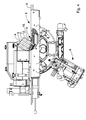
Figure 1 is a perspective view of a spindle moulder; -
Figure 2 is an enlarged detail ofFigure 1 ; -
Figure 3 is a front view of the detail inFigure 2 ; -
Figure 4 is a side view of the detail inFigure 2 ; -
Figure 5 is an enlarged detail ofFigure 4 ; -
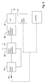
Figure 6 is an operating diagram of the anti-collision system according to the invention; -
Figure 7 is a version of the operating diagram of the anti-collision system according to the invention; -
Figure 8 is a further version of the operating diagram of the anti-collision system according to the invention. - With reference to
Figure 1 , there is shown aspindle moulder 1 for machining workpieces that are not shown that are made of wood or similar materials. - The
spindle moulder 1 comprises a milling tool 2 (Figures 2 to 5 ) and a supportingplane 3 that is substantially horizontal for supporting the workpieces. - The
tool 2, which is operationally positioned above the supportingplane 3, is mounted on aspindle shaft 4 that is rotatable around a rotation axis thereof X (Figures 2 to 5 ) by an actuator of first actuating means, which is not shown, of a first movement unit 8 (Figures 2 to 4 ). - This first actuating means further comprises further actuators arranged for tilting the
spindle shaft 4, and thetool 2 therewith, with respect to the supportingplane 3 along a curved trajectory towards and away from the supportingplane 3, and for moving axially thespindle shaft 4, and thetool 2 therewith, along the rotation axis X for each tilt. - In this manner, in use, it is possible to adjust both a working height of the
tool 2 and a tilt of thetool 2 with respect to the supportingplane 3 according to the dimensions of the workpiece and to the type of machining that it is desired to perform. - In one embodiment of the invention, which is not shown, the
spindle shaft 4 is fixed, i.e. it is not tiltable, with respect to the supportingplane 3. - The aforesaid supporting
plane 3 comprises amovable plane 5, facing and movable towards and away from the tool 2 (Figures 1 to 4 ). - In use, depending on the position of the
spindle shaft 4 with respect to the supportingplane 3 and of a diameter of thetool 2, theplane 5 is driven manually or by one or more actuators of second actuating means that are not shown of a second movement unit towards or away from thetool 2 in such a manner as to enable the workpiece to be supported correctly. - The
spindle moulder 1 further comprises afirst guide 6 and asecond guide 7 that are movable, thefirst guide 6 and thesecond guide 7 are supported by and extend substantially perpendicularly to the supportingplane 3 to guide, during machining, the workpieces along the supporting plane 3 (Figures 1 to 3 ). - In particular, the
first guide 6 and thesecond guide 7 are substantially aligned and are positioned near and on opposite side to thetool 2. - In other words, in use, the
tool 2 is operationally positioned between thefirst guide 6 and thesecond guide 7. In use, depending on the position of thespindle shaft 4 with respect to the supportingplane 3 and on a diameter of thetool 2, thefirst guide 6 and thesecond guide 7 are driven manually and/or by one or more actuators of third actuating means, which are not shown, of a third movement unit, towards or away from thetool 2 in such a manner as to enable the workpiece to be supported correctly. - The
spindle moulder 1 further comprises an anti-collision system arranged for preventing, as will be disclosed better below, thetool 2 from colliding with anend portion 9, provided with a curved edge, that is not shown, of theplane 5 and with respectivefurther end portions first guide 6 and of thesecond guide 7, theend portion 9 and thefurther end portions tool 2 during a relative movement between theend portion 9 and thetool 2 and between the latter and thefurther end portions spindle shaft 4 is stationary or rotated. - This anti-collision system comprises connecting means, which is not shown, for earthing the
tool 2 via abase 18 of thespindle moulder 1, which is earthed in turn (Figure 1 ). Also, the anti-collision system comprises electric conductingelements 12, made of a conducting material, for example aluminium or copper. - Such electric conducting
elements 12 are positioned above, in such a manner as to protrude at least partially from, parts of thespindle moulder 1 that can come into contact with thetool 2 during the relative movement between the latter and these parts. - In particular, the electric conducting
elements 12 are positioned above theend portion 9 and above thefurther end portions - More precisely, the electric conducting
elements 12 are positioned above theend portion 9 and above thefurther end portions end portion 9 and from thefurther end portions - Between the
end portion 9 and the electric conductingelements 12 and between the latter and thefurther end portions Figures 4 and5 ), for example made of nylon, for insulating electrically the electric conductingelements 12 from theend portion 9 and from thefurther end portions - In one embodiment of the invention, which is not shown, the
end portion 9 and thefurther end portions elements 12 are fixed directly on theend portion 9 and on thefurther end portions end portion 9 and from thefurther end portions - In a further embodiment of the invention, which is not shown, the electric conducting
elements 12 are buried, in particular housed, in and partially project from the parts of thespindle moulder 1 that can come into contact with thetool 2 during the relative movement between the latter and these parts. - More precisely, in this embodiment, the electric conducting
elements 12 are positioned inside theend portion 9 and inside thefurther end portions end portion 9 and from thefurther end portions - The anti-collision system further comprises a
generator 13 of electric voltage that is shown schematically inFigures 6 and 7 . - The
generator 13, for example a transformer, is arranged for feeding a potential difference between theelectric conducting elements 12 and thetool 2, theelectric conducting elements 12 being feedable at a voltage of at least 6000V, for example comprised between 8000 and 10000V. In particular, the transformer is arranged for generating a low-amperage current that is not dangerous for the operator. Also, the anti-collision system includes acontrol system 15, shown schematically inFigures 6 and 7 , configured in such a manner as to detect, substantially at a certain distance, for example comprised between 1mm and 10mm, between thetool 2 and theelectric conducting elements 12, a current passage between theelectric conducting elements 12 and thetool 2, and to emit a correspondinganti-collision control signal 14 when it detects this current passage. - This current passage is achieved in the form of an electric arc that passes between one or more of the
electric conducting elements 12 fed with voltage and the earthedtool 2 substantially at the aforesaid distance, for example comprised between 1mm and 10mm. - In other words, the electric potential difference that is established at the aforesaid distance between one or more of the
electric conducting elements 12 fed with voltage and the earthedtool 2 creates a spark that is detected by thecontrol system 15 in the form of a electric current passage. Further, thecontrol system 15, for example comprising a microprocessor, controls theelectric voltage generator 13 in such a manner that theelectric voltage generator 13 feeds the electric voltage to theelectric conducting elements 12 when the first actuating means moves thetool 2 and/or the second actuating means moves theplane 5 and/or the third actuating means moves thefirst guide 6 and/or thesecond guide 7, and respectively in such a manner that theelectric voltage generator 13 does not feed the electric voltage to theelectric conducting elements 12 when the aforesaid current passage is detected. - In other words, the
electric conducting elements 12 are not fed with voltage constantly but only during a relative movement between theend portion 9 and thetool 2 and between the latter and thefurther end portions - At the moment in which the aforesaid current passage is detected, the
control system 15 sends theanti-collision control signal 14 to the actuators of the first actuating means of thefirst movement unit 8, of the second actuating means of the second movement unit and of the third actuating means of the third movement unit that automatically lock respectively the movement of thetool 2, of theplane 5 and of thefirst guide 6 and of the second guide 7 (Figure 6 ). In this manner, in the case of aspindle moulder 1 with all the movements motor-driven, it is possible, once the aforesaid current passage has been detected, to lock automatically the movement of thetool 2, of theplane 5, of thefirst guide 6 and of thesecond guide 7. - In another embodiment of the invention, shown schematically in
Figure 7 , theanti-collision control signal 14 is sent to analarm system 17. - The
alarm system 17 is arranged for emitting an alarm warning, for example an acoustic and/or luminous alarm warning, and/or for controlling a locking device, which is not shown, arranged for locking the movement of thetool 2 and of themachine part anti-collision control signal 14. - This locking device can be, for example, of pneumatic or electromagnetic type.
- In this manner, in the case of a
spindle moulder 1 with manual movements, once the aforesaid current passage has been detected, it is possible to alert the operator to the imminent collision and/or lock the movement of thetool 2, of theplane 5, of thefirst guide 6 and of thesecond guide 7, preventing the operator from acting on the manual movements. - In a further embodiment of the invention, shown schematically in
Figure 8 , theanti-collision control signal 14 is sent both to thealarm system 17 and to the actuators of the first actuating means, if present, and/or of the second actuating means, if present, and/or of the third actuating means, if present. - In this manner, in the case of a
spindle moulder 1 with some motor-driven movements and with other manual movements, it is possible, once the aforesaid current passage has been detected, to alert the operator to the imminent collision and/or lock the manual movements that are present by means of the locking device and/or automatically lock the motor-driven movements present. - Also, in another embodiment of the invention, which is not shown, the
anti-collision control signal 14 can be sent only to a pneumatic locking device arranged for locking the movement of thetool 2, of theplane 5, of thefirst guide 6 and of thesecond guide 7. - Also in another further embodiment of the invention, which is not shown, in the case of a spindle moulder provided with an electronic control, the control signal can be sent to a control and management unit of the spindle moulder.
- It should be noted that the aforesaid anti-collision device can be used in any machine tool in which it is required to avoid the collision between one part thereof and a further part thereof that are movable one relatively the other.
- It should be noted how the anti-collision system according to the invention is safer and cheaper than known anti-collision systems.
- In fact, the anti-collision system according to the invention does not require the electronic control with which known anti-collision systems are provided.
- In fact, owing to the detection of the aforesaid current passage, it is possible to obtain a measurement of the distance that is not subject to human errors.
- Further, the anti-collision system according to the invention does not require the spindle moulder to be provided with an electronic control having great calculating capacities.
- In fact, the
anti-collision control signal 14 can be sent, for example directly to the first actuating means of thefirst movement unit 8, to the second actuating means of the second movement unit and to the third actuating means of the third movement unit and/or to thealarm system 17 so as to lock the movement of thetool 2, of theplane 5, and of thefirst guide 6 and of thesecond guide 7.
Claims (15)
- Anti-collision system for a machine (1) for machining workpieces of wood or similar materials, said machine (1) including a tool (2) and a machine part (9, 10, 11) positioned near said tool (2), said tool (2) and said machine part (9, 10, 11) being movable one relatively the other, said system further comprising electric conducting means (12) projecting at least partially from said machine part (9, 10, 11), electric voltage generating means (13) for feeding a potential difference between said electric conducting means (12) and said tool (2) and control means (15) configured in such a way as to detect, substantially at a distance between said tool (2) and said electric conducting means (12), a current passage between said electric conducting means (12) and said tool (2), and to emit a corresponding anti-collision control signal (14) as said current passage is detected, characterised in that said electric conducting means (12) is buried, at least partially, in said machine part (9, 10, 11).
- System according to claim 1, and comprising connecting means for earthing said tool (2).
- System according to claim 1, or 2, wherein said electric voltage generating means (13) feeds said electric conducting means (12) with a voltage of at least 6000V.
- System according to any preceding claim, wherein said control means (15) controls said electric voltage generating means (13) in such a manner that said electric voltage generating means (13) feeds said electric voltage to said electric conducting means (12) when respective movement means of said tool (2) and of said machine part (9, 10, 11) move said tool (2) and/or said machine part (9, 10, 11) one relatively the other, and respectively in such a manner that said electric voltage generating means (13) does not feed said electric voltage to said electric conducting means (12) after said control means (15) detects said current passage.
- System according to claim 4, wherein said control means (15) transmits said anti-collision control signal (14) to said respective movement means for locking the movement of said tool (2) and of said machine part (9, 10, 11), and/or to an alarm system (17) arranged for emitting an alarm warning when it receives said anti-collision control signal (14), or to a control and management unit of said machine (1).
- System according to claim 5, wherein said alarm system (17) is arranged for controlling a locking device arranged for locking the movement of said tool (2) and of said machine part (9, 10, 11).
- System according to any preceding claim, wherein said controlling means (15) comprises a microprocessor.
- System according to any preceding claim, wherein said machine part (9, 10, 11) is made of insulating material.
- System according to any preceding claim, and comprising insulating means (16) interposed between said electric conducting means (12) and said machine part (9, 10, 11) for insulating said electric conducting means (12) from said machine part (9, 10, 11).
- System according to any preceding claim, wherein said electric voltage generating means (13) comprises a transformer.
- System according to any preceding claim, wherein said machine is a spindle moulder (1), said spindle moulder (1) comprising a substantially horizontal supporting plane (3) for supporting said workpieces and a first guide element (6) and a second guide element (7) supported by and extending substantially perpendicularly to said supporting plane (3), for guiding said workpieces along said supporting plane (3), said first guide element (6) and said second guide element (7) being substantially aligned and being positioned on opposite sides of said tool (2).
- System according to claim 11, wherein said machine part (9, 10, 11) comprises an end portion (9) of a movable part (5) of said supporting plane (3), said movable part (5) facing and being movable towards and away from said tool (2).
- System according to claim 11, or 12, wherein said machine part (9, 10, 11) comprises respective further end portions (10, 11) of said first guide element (6) and of said second guide element (7), said further end portions (10, 11) facing, and being positioned on opposite sides of, said tool (2).
- Machine (1) for machining workpieces made of wood or similar materials, comprising an anti-collision system as claimed in any preceding claim.
- Anti-collision method for preventing a collision between a tool (2) of a machine (1) for machining workpieces made of wood or similar materials and a part (9, 10, 11) of said machine which is near said tool (2), said tool (2) and said machine part (9, 10, 11) being movable one relatively the other, characterised in that comprises positioning electric conducting means (12) on said machine part (9, 10, 11) in such a manner that said electric conducting means (12) projects at least partially from said machine part (9, 10, 11), feeding a potential difference between said electric conducting means (12) and said tool (2), detecting, substantially at a distance between said tool (2) and said electric conducting means (12), a current passage between said electric conducting means (12) and said tool (2) and emitting a corresponding anti-collision control signal (14) as said current passage is detected.
Applications Claiming Priority (1)
| Application Number | Priority Date | Filing Date | Title |
|---|---|---|---|
| ITMO2010A000259A IT1402053B1 (en) | 2010-09-15 | 2010-09-15 | ANTI-COLLISION SYSTEM AND METHOD |
Publications (2)
| Publication Number | Publication Date |
|---|---|
| EP2431123A1 true EP2431123A1 (en) | 2012-03-21 |
| EP2431123B1 EP2431123B1 (en) | 2014-11-26 |
Family
ID=43738999
Family Applications (1)
| Application Number | Title | Priority Date | Filing Date |
|---|---|---|---|
| EP20110181293 Active EP2431123B1 (en) | 2010-09-15 | 2011-09-14 | Anti-collision system and method |
Country Status (2)
| Country | Link |
|---|---|
| EP (1) | EP2431123B1 (en) |
| IT (1) | IT1402053B1 (en) |
Cited By (1)
| Publication number | Priority date | Publication date | Assignee | Title |
|---|---|---|---|---|
| CN104985478A (en) * | 2015-07-31 | 2015-10-21 | 江苏邦德机械科技发展有限公司 | Rim charge collection device in numerical control processing |
Citations (2)
| Publication number | Priority date | Publication date | Assignee | Title |
|---|---|---|---|---|
| FR2633551A1 (en) * | 1988-06-22 | 1990-01-05 | Delbeke James | PROTECTIVE DEVICE FOR SAWING APPARATUS AND APPARATUS PROVIDED WITH SUCH A DEVICE |
| US20090048713A1 (en) * | 2005-04-01 | 2009-02-19 | Siemens Aktiengesellschaft | Method and control device for targeted reaction in the event of a contact between a machine element of a machine and an object |
-
2010
- 2010-09-15 IT ITMO2010A000259A patent/IT1402053B1/en active
-
2011
- 2011-09-14 EP EP20110181293 patent/EP2431123B1/en active Active
Patent Citations (2)
| Publication number | Priority date | Publication date | Assignee | Title |
|---|---|---|---|---|
| FR2633551A1 (en) * | 1988-06-22 | 1990-01-05 | Delbeke James | PROTECTIVE DEVICE FOR SAWING APPARATUS AND APPARATUS PROVIDED WITH SUCH A DEVICE |
| US20090048713A1 (en) * | 2005-04-01 | 2009-02-19 | Siemens Aktiengesellschaft | Method and control device for targeted reaction in the event of a contact between a machine element of a machine and an object |
Cited By (1)
| Publication number | Priority date | Publication date | Assignee | Title |
|---|---|---|---|---|
| CN104985478A (en) * | 2015-07-31 | 2015-10-21 | 江苏邦德机械科技发展有限公司 | Rim charge collection device in numerical control processing |
Also Published As
| Publication number | Publication date |
|---|---|
| ITMO20100259A1 (en) | 2012-03-16 |
| EP2431123B1 (en) | 2014-11-26 |
| IT1402053B1 (en) | 2013-08-28 |
Similar Documents
| Publication | Publication Date | Title |
|---|---|---|
| US10220475B2 (en) | Machines for the separative machining of plate-shaped workpieces | |
| US20090251252A1 (en) | Electromagnetic work holding system | |
| CN105436980A (en) | High voltage crash prevention device for machine tools | |
| KR20100008535A (en) | Device for processing bus bar | |
| CN107931855B (en) | Pipe clamping inhibition method for pipe cutting machine and laser pipe cutting machine | |
| KR102176958B1 (en) | Laser processing machine | |
| CN109475920B (en) | Workpiece processing machine and method for operating the same | |
| JPS62286683A (en) | Projection welding equipment | |
| EP3488966B1 (en) | Automatic lathe | |
| US11413674B2 (en) | Deforming machine | |
| EP2431123B1 (en) | Anti-collision system and method | |
| EP2974819B1 (en) | Arc welding system, method for performing arc welding | |
| KR20160002653A (en) | Angle cutting machine | |
| WO2021145860A1 (en) | System for processing a workpiece | |
| KR20150106525A (en) | Angle cutting machine | |
| CN108480990B (en) | Full-automatic drilling and tapping device | |
| KR20150109856A (en) | Plasma Cutting Machine | |
| CN108971734B (en) | Go up unloader and production line | |
| KR101379169B1 (en) | The wire cutter unit for movable welding robot | |
| EP1637251B1 (en) | Spring manufacturing machine comprising a wire feeder driving mechanism | |
| CN210848758U (en) | Automatic welding production line for auxiliary pole of automobile starter stator | |
| CN106985176A (en) | A kind of insulating sleeve cutting means | |
| CN114408536A (en) | Crystal bar overturning device and crystal bar overturning method | |
| JP6759159B2 (en) | Interference detector | |
| EP1777034B1 (en) | Detachable indicator device for feeding machine |
Legal Events
| Date | Code | Title | Description |
|---|---|---|---|
| PUAI | Public reference made under article 153(3) epc to a published international application that has entered the european phase |
Free format text: ORIGINAL CODE: 0009012 |
|
| AK | Designated contracting states |
Kind code of ref document: A1 Designated state(s): AL AT BE BG CH CY CZ DE DK EE ES FI FR GB GR HR HU IE IS IT LI LT LU LV MC MK MT NL NO PL PT RO RS SE SI SK SM TR |
|
| AX | Request for extension of the european patent |
Extension state: BA ME |
|
| 17P | Request for examination filed |
Effective date: 20120910 |
|
| 17Q | First examination report despatched |
Effective date: 20131030 |
|
| GRAP | Despatch of communication of intention to grant a patent |
Free format text: ORIGINAL CODE: EPIDOSNIGR1 |
|
| INTG | Intention to grant announced |
Effective date: 20140623 |
|
| GRAS | Grant fee paid |
Free format text: ORIGINAL CODE: EPIDOSNIGR3 |
|
| GRAA | (expected) grant |
Free format text: ORIGINAL CODE: 0009210 |
|
| AK | Designated contracting states |
Kind code of ref document: B1 Designated state(s): AL AT BE BG CH CY CZ DE DK EE ES FI FR GB GR HR HU IE IS IT LI LT LU LV MC MK MT NL NO PL PT RO RS SE SI SK SM TR |
|
| REG | Reference to a national code |
Ref country code: GB Ref legal event code: FG4D |
|
| RIN1 | Information on inventor provided before grant (corrected) |
Inventor name: GABRIELLI, VALTER Inventor name: BALSAMINI, GUGLIELMO |
|
| REG | Reference to a national code |
Ref country code: CH Ref legal event code: EP |
|
| REG | Reference to a national code |
Ref country code: AT Ref legal event code: REF Ref document number: 697893 Country of ref document: AT Kind code of ref document: T Effective date: 20141215 |
|
| REG | Reference to a national code |
Ref country code: IE Ref legal event code: FG4D |
|
| REG | Reference to a national code |
Ref country code: DE Ref legal event code: R096 Ref document number: 602011011688 Country of ref document: DE Effective date: 20150108 |
|
| REG | Reference to a national code |
Ref country code: NL Ref legal event code: VDEP Effective date: 20141126 |
|
| REG | Reference to a national code |
Ref country code: LT Ref legal event code: MG4D |
|
| PG25 | Lapsed in a contracting state [announced via postgrant information from national office to epo] |
Ref country code: IS Free format text: LAPSE BECAUSE OF FAILURE TO SUBMIT A TRANSLATION OF THE DESCRIPTION OR TO PAY THE FEE WITHIN THE PRESCRIBED TIME-LIMIT Effective date: 20150326 Ref country code: FI Free format text: LAPSE BECAUSE OF FAILURE TO SUBMIT A TRANSLATION OF THE DESCRIPTION OR TO PAY THE FEE WITHIN THE PRESCRIBED TIME-LIMIT Effective date: 20141126 Ref country code: NL Free format text: LAPSE BECAUSE OF FAILURE TO SUBMIT A TRANSLATION OF THE DESCRIPTION OR TO PAY THE FEE WITHIN THE PRESCRIBED TIME-LIMIT Effective date: 20141126 Ref country code: PT Free format text: LAPSE BECAUSE OF FAILURE TO SUBMIT A TRANSLATION OF THE DESCRIPTION OR TO PAY THE FEE WITHIN THE PRESCRIBED TIME-LIMIT Effective date: 20150326 Ref country code: NO Free format text: LAPSE BECAUSE OF FAILURE TO SUBMIT A TRANSLATION OF THE DESCRIPTION OR TO PAY THE FEE WITHIN THE PRESCRIBED TIME-LIMIT Effective date: 20150226 Ref country code: ES Free format text: LAPSE BECAUSE OF FAILURE TO SUBMIT A TRANSLATION OF THE DESCRIPTION OR TO PAY THE FEE WITHIN THE PRESCRIBED TIME-LIMIT Effective date: 20141126 Ref country code: LT Free format text: LAPSE BECAUSE OF FAILURE TO SUBMIT A TRANSLATION OF THE DESCRIPTION OR TO PAY THE FEE WITHIN THE PRESCRIBED TIME-LIMIT Effective date: 20141126 |
|
| PG25 | Lapsed in a contracting state [announced via postgrant information from national office to epo] |
Ref country code: SE Free format text: LAPSE BECAUSE OF FAILURE TO SUBMIT A TRANSLATION OF THE DESCRIPTION OR TO PAY THE FEE WITHIN THE PRESCRIBED TIME-LIMIT Effective date: 20141126 Ref country code: HR Free format text: LAPSE BECAUSE OF FAILURE TO SUBMIT A TRANSLATION OF THE DESCRIPTION OR TO PAY THE FEE WITHIN THE PRESCRIBED TIME-LIMIT Effective date: 20141126 Ref country code: GR Free format text: LAPSE BECAUSE OF FAILURE TO SUBMIT A TRANSLATION OF THE DESCRIPTION OR TO PAY THE FEE WITHIN THE PRESCRIBED TIME-LIMIT Effective date: 20150227 Ref country code: LV Free format text: LAPSE BECAUSE OF FAILURE TO SUBMIT A TRANSLATION OF THE DESCRIPTION OR TO PAY THE FEE WITHIN THE PRESCRIBED TIME-LIMIT Effective date: 20141126 Ref country code: RS Free format text: LAPSE BECAUSE OF FAILURE TO SUBMIT A TRANSLATION OF THE DESCRIPTION OR TO PAY THE FEE WITHIN THE PRESCRIBED TIME-LIMIT Effective date: 20141126 Ref country code: CY Free format text: LAPSE BECAUSE OF FAILURE TO SUBMIT A TRANSLATION OF THE DESCRIPTION OR TO PAY THE FEE WITHIN THE PRESCRIBED TIME-LIMIT Effective date: 20141126 |
|
| PG25 | Lapsed in a contracting state [announced via postgrant information from national office to epo] |
Ref country code: CZ Free format text: LAPSE BECAUSE OF FAILURE TO SUBMIT A TRANSLATION OF THE DESCRIPTION OR TO PAY THE FEE WITHIN THE PRESCRIBED TIME-LIMIT Effective date: 20141126 Ref country code: EE Free format text: LAPSE BECAUSE OF FAILURE TO SUBMIT A TRANSLATION OF THE DESCRIPTION OR TO PAY THE FEE WITHIN THE PRESCRIBED TIME-LIMIT Effective date: 20141126 Ref country code: DK Free format text: LAPSE BECAUSE OF FAILURE TO SUBMIT A TRANSLATION OF THE DESCRIPTION OR TO PAY THE FEE WITHIN THE PRESCRIBED TIME-LIMIT Effective date: 20141126 Ref country code: RO Free format text: LAPSE BECAUSE OF FAILURE TO SUBMIT A TRANSLATION OF THE DESCRIPTION OR TO PAY THE FEE WITHIN THE PRESCRIBED TIME-LIMIT Effective date: 20141126 Ref country code: SK Free format text: LAPSE BECAUSE OF FAILURE TO SUBMIT A TRANSLATION OF THE DESCRIPTION OR TO PAY THE FEE WITHIN THE PRESCRIBED TIME-LIMIT Effective date: 20141126 |
|
| REG | Reference to a national code |
Ref country code: DE Ref legal event code: R097 Ref document number: 602011011688 Country of ref document: DE |
|
| PG25 | Lapsed in a contracting state [announced via postgrant information from national office to epo] |
Ref country code: PL Free format text: LAPSE BECAUSE OF FAILURE TO SUBMIT A TRANSLATION OF THE DESCRIPTION OR TO PAY THE FEE WITHIN THE PRESCRIBED TIME-LIMIT Effective date: 20141126 |
|
| PLBE | No opposition filed within time limit |
Free format text: ORIGINAL CODE: 0009261 |
|
| STAA | Information on the status of an ep patent application or granted ep patent |
Free format text: STATUS: NO OPPOSITION FILED WITHIN TIME LIMIT |
|
| 26N | No opposition filed |
Effective date: 20150827 |
|
| PG25 | Lapsed in a contracting state [announced via postgrant information from national office to epo] |
Ref country code: SI Free format text: LAPSE BECAUSE OF FAILURE TO SUBMIT A TRANSLATION OF THE DESCRIPTION OR TO PAY THE FEE WITHIN THE PRESCRIBED TIME-LIMIT Effective date: 20141126 |
|
| PG25 | Lapsed in a contracting state [announced via postgrant information from national office to epo] |
Ref country code: MC Free format text: LAPSE BECAUSE OF FAILURE TO SUBMIT A TRANSLATION OF THE DESCRIPTION OR TO PAY THE FEE WITHIN THE PRESCRIBED TIME-LIMIT Effective date: 20141126 Ref country code: LU Free format text: LAPSE BECAUSE OF FAILURE TO SUBMIT A TRANSLATION OF THE DESCRIPTION OR TO PAY THE FEE WITHIN THE PRESCRIBED TIME-LIMIT Effective date: 20150914 |
|
| REG | Reference to a national code |
Ref country code: CH Ref legal event code: PL |
|
| REG | Reference to a national code |
Ref country code: AT Ref legal event code: UEP Ref document number: 697893 Country of ref document: AT Kind code of ref document: T Effective date: 20141126 |
|
| GBPC | Gb: european patent ceased through non-payment of renewal fee |
Effective date: 20150914 |
|
| REG | Reference to a national code |
Ref country code: IE Ref legal event code: MM4A |
|
| REG | Reference to a national code |
Ref country code: FR Ref legal event code: ST Effective date: 20160531 |
|
| PG25 | Lapsed in a contracting state [announced via postgrant information from national office to epo] |
Ref country code: CH Free format text: LAPSE BECAUSE OF NON-PAYMENT OF DUE FEES Effective date: 20150930 Ref country code: LI Free format text: LAPSE BECAUSE OF NON-PAYMENT OF DUE FEES Effective date: 20150930 Ref country code: GB Free format text: LAPSE BECAUSE OF NON-PAYMENT OF DUE FEES Effective date: 20150914 Ref country code: IE Free format text: LAPSE BECAUSE OF NON-PAYMENT OF DUE FEES Effective date: 20150914 |
|
| PG25 | Lapsed in a contracting state [announced via postgrant information from national office to epo] |
Ref country code: FR Free format text: LAPSE BECAUSE OF NON-PAYMENT OF DUE FEES Effective date: 20150930 |
|
| PG25 | Lapsed in a contracting state [announced via postgrant information from national office to epo] |
Ref country code: MT Free format text: LAPSE BECAUSE OF FAILURE TO SUBMIT A TRANSLATION OF THE DESCRIPTION OR TO PAY THE FEE WITHIN THE PRESCRIBED TIME-LIMIT Effective date: 20141126 |
|
| PG25 | Lapsed in a contracting state [announced via postgrant information from national office to epo] |
Ref country code: HU Free format text: LAPSE BECAUSE OF FAILURE TO SUBMIT A TRANSLATION OF THE DESCRIPTION OR TO PAY THE FEE WITHIN THE PRESCRIBED TIME-LIMIT; INVALID AB INITIO Effective date: 20110914 Ref country code: BG Free format text: LAPSE BECAUSE OF FAILURE TO SUBMIT A TRANSLATION OF THE DESCRIPTION OR TO PAY THE FEE WITHIN THE PRESCRIBED TIME-LIMIT Effective date: 20141126 Ref country code: SM Free format text: LAPSE BECAUSE OF FAILURE TO SUBMIT A TRANSLATION OF THE DESCRIPTION OR TO PAY THE FEE WITHIN THE PRESCRIBED TIME-LIMIT Effective date: 20141126 |
|
| PG25 | Lapsed in a contracting state [announced via postgrant information from national office to epo] |
Ref country code: TR Free format text: LAPSE BECAUSE OF FAILURE TO SUBMIT A TRANSLATION OF THE DESCRIPTION OR TO PAY THE FEE WITHIN THE PRESCRIBED TIME-LIMIT Effective date: 20141126 |
|
| PG25 | Lapsed in a contracting state [announced via postgrant information from national office to epo] |
Ref country code: BE Free format text: LAPSE BECAUSE OF FAILURE TO SUBMIT A TRANSLATION OF THE DESCRIPTION OR TO PAY THE FEE WITHIN THE PRESCRIBED TIME-LIMIT Effective date: 20141126 |
|
| PG25 | Lapsed in a contracting state [announced via postgrant information from national office to epo] |
Ref country code: MK Free format text: LAPSE BECAUSE OF FAILURE TO SUBMIT A TRANSLATION OF THE DESCRIPTION OR TO PAY THE FEE WITHIN THE PRESCRIBED TIME-LIMIT Effective date: 20141126 |
|
| PG25 | Lapsed in a contracting state [announced via postgrant information from national office to epo] |
Ref country code: AL Free format text: LAPSE BECAUSE OF FAILURE TO SUBMIT A TRANSLATION OF THE DESCRIPTION OR TO PAY THE FEE WITHIN THE PRESCRIBED TIME-LIMIT Effective date: 20141126 |
|
| P01 | Opt-out of the competence of the unified patent court (upc) registered |
Effective date: 20230518 |
|
| PGFP | Annual fee paid to national office [announced via postgrant information from national office to epo] |
Ref country code: DE Payment date: 20250919 Year of fee payment: 15 |
|
| PGFP | Annual fee paid to national office [announced via postgrant information from national office to epo] |
Ref country code: IT Payment date: 20250708 Year of fee payment: 15 |
|
| PGFP | Annual fee paid to national office [announced via postgrant information from national office to epo] |
Ref country code: AT Payment date: 20250918 Year of fee payment: 15 |